EP4530138A1 - Trailer control valve and trailer braking system - Google Patents
Trailer control valve and trailer braking system Download PDFInfo
- Publication number
- EP4530138A1 EP4530138A1 EP24201884.4A EP24201884A EP4530138A1 EP 4530138 A1 EP4530138 A1 EP 4530138A1 EP 24201884 A EP24201884 A EP 24201884A EP 4530138 A1 EP4530138 A1 EP 4530138A1
- Authority
- EP
- European Patent Office
- Prior art keywords
- valve
- control
- chamber
- trailer
- control valve
- Prior art date
- Legal status (The legal status is an assumption and is not a legal conclusion. Google has not performed a legal analysis and makes no representation as to the accuracy of the status listed.)
- Granted
Links
Images



Classifications
-
- B—PERFORMING OPERATIONS; TRANSPORTING
- B60—VEHICLES IN GENERAL
- B60T—VEHICLE BRAKE CONTROL SYSTEMS OR PARTS THEREOF; BRAKE CONTROL SYSTEMS OR PARTS THEREOF, IN GENERAL; ARRANGEMENT OF BRAKING ELEMENTS ON VEHICLES IN GENERAL; PORTABLE DEVICES FOR PREVENTING UNWANTED MOVEMENT OF VEHICLES; VEHICLE MODIFICATIONS TO FACILITATE COOLING OF BRAKES
- B60T7/00—Brake-action initiating means
- B60T7/12—Brake-action initiating means for automatic initiation; for initiation not subject to will of driver or passenger
- B60T7/20—Brake-action initiating means for automatic initiation; for initiation not subject to will of driver or passenger specially for trailers, e.g. in case of uncoupling of or overrunning by trailer
-
- B—PERFORMING OPERATIONS; TRANSPORTING
- B60—VEHICLES IN GENERAL
- B60T—VEHICLE BRAKE CONTROL SYSTEMS OR PARTS THEREOF; BRAKE CONTROL SYSTEMS OR PARTS THEREOF, IN GENERAL; ARRANGEMENT OF BRAKING ELEMENTS ON VEHICLES IN GENERAL; PORTABLE DEVICES FOR PREVENTING UNWANTED MOVEMENT OF VEHICLES; VEHICLE MODIFICATIONS TO FACILITATE COOLING OF BRAKES
- B60T15/00—Construction arrangement, or operation of valves incorporated in power brake systems and not covered by groups B60T11/00 or B60T13/00
- B60T15/02—Application and release valves
- B60T15/18—Triple or other relay valves which allow step-wise application or release and which are actuated by brake-pipe pressure variation to connect brake cylinders or equivalent to compressed air or vacuum source or atmosphere
- B60T15/181—Trailer control valves
-
- B—PERFORMING OPERATIONS; TRANSPORTING
- B60—VEHICLES IN GENERAL
- B60T—VEHICLE BRAKE CONTROL SYSTEMS OR PARTS THEREOF; BRAKE CONTROL SYSTEMS OR PARTS THEREOF, IN GENERAL; ARRANGEMENT OF BRAKING ELEMENTS ON VEHICLES IN GENERAL; PORTABLE DEVICES FOR PREVENTING UNWANTED MOVEMENT OF VEHICLES; VEHICLE MODIFICATIONS TO FACILITATE COOLING OF BRAKES
- B60T13/00—Transmitting braking action from initiating means to ultimate brake actuator with power assistance or drive; Brake systems incorporating such transmitting means, e.g. air-pressure brake systems
- B60T13/10—Transmitting braking action from initiating means to ultimate brake actuator with power assistance or drive; Brake systems incorporating such transmitting means, e.g. air-pressure brake systems with fluid assistance, drive, or release
- B60T13/24—Transmitting braking action from initiating means to ultimate brake actuator with power assistance or drive; Brake systems incorporating such transmitting means, e.g. air-pressure brake systems with fluid assistance, drive, or release the fluid being gaseous
- B60T13/26—Compressed-air systems
- B60T13/261—Compressed-air systems systems with both indirect application and application by springs or weights and released by compressed air
- B60T13/263—Compressed-air systems systems with both indirect application and application by springs or weights and released by compressed air specially adapted for coupling with dependent systems, e.g. tractor-trailer systems
-
- B—PERFORMING OPERATIONS; TRANSPORTING
- B60—VEHICLES IN GENERAL
- B60T—VEHICLE BRAKE CONTROL SYSTEMS OR PARTS THEREOF; BRAKE CONTROL SYSTEMS OR PARTS THEREOF, IN GENERAL; ARRANGEMENT OF BRAKING ELEMENTS ON VEHICLES IN GENERAL; PORTABLE DEVICES FOR PREVENTING UNWANTED MOVEMENT OF VEHICLES; VEHICLE MODIFICATIONS TO FACILITATE COOLING OF BRAKES
- B60T13/00—Transmitting braking action from initiating means to ultimate brake actuator with power assistance or drive; Brake systems incorporating such transmitting means, e.g. air-pressure brake systems
- B60T13/10—Transmitting braking action from initiating means to ultimate brake actuator with power assistance or drive; Brake systems incorporating such transmitting means, e.g. air-pressure brake systems with fluid assistance, drive, or release
- B60T13/66—Electrical control in fluid-pressure brake systems
- B60T13/68—Electrical control in fluid-pressure brake systems by electrically-controlled valves
- B60T13/683—Electrical control in fluid-pressure brake systems by electrically-controlled valves in pneumatic systems or parts thereof
-
- B—PERFORMING OPERATIONS; TRANSPORTING
- B60—VEHICLES IN GENERAL
- B60T—VEHICLE BRAKE CONTROL SYSTEMS OR PARTS THEREOF; BRAKE CONTROL SYSTEMS OR PARTS THEREOF, IN GENERAL; ARRANGEMENT OF BRAKING ELEMENTS ON VEHICLES IN GENERAL; PORTABLE DEVICES FOR PREVENTING UNWANTED MOVEMENT OF VEHICLES; VEHICLE MODIFICATIONS TO FACILITATE COOLING OF BRAKES
- B60T15/00—Construction arrangement, or operation of valves incorporated in power brake systems and not covered by groups B60T11/00 or B60T13/00
- B60T15/02—Application and release valves
- B60T15/18—Triple or other relay valves which allow step-wise application or release and which are actuated by brake-pipe pressure variation to connect brake cylinders or equivalent to compressed air or vacuum source or atmosphere
- B60T15/182—Trailer brake valves
-
- B—PERFORMING OPERATIONS; TRANSPORTING
- B60—VEHICLES IN GENERAL
- B60T—VEHICLE BRAKE CONTROL SYSTEMS OR PARTS THEREOF; BRAKE CONTROL SYSTEMS OR PARTS THEREOF, IN GENERAL; ARRANGEMENT OF BRAKING ELEMENTS ON VEHICLES IN GENERAL; PORTABLE DEVICES FOR PREVENTING UNWANTED MOVEMENT OF VEHICLES; VEHICLE MODIFICATIONS TO FACILITATE COOLING OF BRAKES
- B60T8/00—Arrangements for adjusting wheel-braking force to meet varying vehicular or ground-surface conditions, e.g. limiting or varying distribution of braking force
- B60T8/17—Using electrical or electronic regulation means to control braking
- B60T8/1701—Braking or traction control means specially adapted for particular types of vehicles
- B60T8/1708—Braking or traction control means specially adapted for particular types of vehicles for lorries or tractor-trailer combinations
-
- B—PERFORMING OPERATIONS; TRANSPORTING
- B60—VEHICLES IN GENERAL
- B60Y—INDEXING SCHEME RELATING TO ASPECTS CROSS-CUTTING VEHICLE TECHNOLOGY
- B60Y2200/00—Type of vehicle
- B60Y2200/10—Road Vehicles
- B60Y2200/14—Trucks; Load vehicles, Busses
- B60Y2200/147—Trailers, e.g. full trailers or caravans
-
- B—PERFORMING OPERATIONS; TRANSPORTING
- B60—VEHICLES IN GENERAL
- B60Y—INDEXING SCHEME RELATING TO ASPECTS CROSS-CUTTING VEHICLE TECHNOLOGY
- B60Y2400/00—Special features of vehicle units
- B60Y2400/81—Braking systems
Definitions
- the present invention relates to the technical field of trailer braking, and in particular to a trailer control valve and a trailer braking system.
- a heavy-duty commercial vehicle is an important logistics transportation tool, and a carrier by which transportation is implemented is a tractor (head) plus a trailer.
- a tractor head
- trailer trailer
- a braking demand of the trailer is implemented by a trailer control valve mounted on the tractor.
- An ordinary trailer control valve can only passively transmit a braking demand from a driver but has no traction control function.
- Traction control can solve the problems from the vehicle such as rollover and start rolling, especially in logistics transportation, where the trailer is often the maximum-loaded in the whole system. Therefore, the traction control over the trailer is significant.
- the present invention provides a trailer control valve having a traction control function and a trailer braking system, in which an ordinary trailer control valve is integrated with a traction control valve, such that a braking force of a trailer can be actively controlled according to the state of a vehicle, realizing active control of traction of the trailer and improving the safety of the whole vehicle.
- a trailer control valve including a control port, a relay valve, an air inlet and a first air outlet, the control port being connected to a control chamber of the relay valve, and the air inlet and the first air outlet being respectively connected to a brake chamber of the relay valve.
- the trailer control valve further includes: a traction control valve arranged in a pipeline from the control port to the control chamber and connected to the air inlet.
- the traction control valve has a first operating state in which the control port is in communication with the control chamber through a first channel of the traction control valve; and the traction control valve has a second operating state in which the air inlet is in communication with the control chamber through a second channel of the traction control valve.
- the traction control valve includes: a first valve member arranged in the pipeline from the control port to the control chamber, the first valve member having a first valve chamber and a second valve chamber which are alternatively opened, and the first valve chamber forming the first channel; and a second valve member connected to the air inlet and the second valve chamber, the second valve member having an air intake valve chamber, and the air intake valve chamber and the second valve chamber forming the second channel.
- the first valve member is a two-way check valve, the two-way check valve having a first inlet connected to the control port, a second inlet connected to the air intake valve chamber and an outlet connected to the control chamber; and a movable valve core is arranged inside a valve chamber of the two-way check valve, and as the valve core moves, the first inlet is in communication with the outlet to open the first valve chamber, or the second inlet is in communication with the outlet to open the second valve chamber.
- the second valve member is a two-position three-way solenoid valve having the air intake valve chamber and an exhaust valve chamber, the air intake valve chamber being connected to the air inlet and the second valve chamber, and the exhaust valve chamber being connected to the second valve chamber.
- an operating state switching control end of the traction control valve is connected to an electronic control unit.
- the traction control valve is integrated into a housing of the trailer control valve.
- control port includes at least one of a first control port and a second control port connected to a foot brake valve.
- the trailer control valve further includes a second air outlet connected to the air inlet.
- the trailer control valve further includes a pneumatic valve arranged in a pipeline from the air inlet to the first air outlet and the second air outlet, a control end of the pneumatic valve being connected to the control chamber.
- a trailer braking system is provided, and the trailer braking system is equipped with a trailer control valve as described in any one of the above embodiments.
- the ordinary trailer control valve is integrated with the traction control valve.
- the control port When the traction control valve is in the first operating state, the control port is in communication with the control chamber through the first channel of the traction control valve, the control port is connected to the foot brake valve, and at this time, braking control over the trailer is realized according to a braking demand from a driver.
- the air inlet When the traction control valve is in the second operating state, the air inlet is in communication with the control chamber through the second channel of the traction control valve.
- the value of the air pressure output by the first air outlet varies with the value of the air pressure from the control chamber.
- the air inlet is connected to an air reservoir of a tractor, and the value of an air pressure output by the air reservoir is automatically adjusted according to the state of the vehicle. At this time, the braking force of the trailer can be actively controlled according to the state of the vehicle.
- the trailer control valve according to the present invention can not only perform braking control over the trailer according to the braking demand from the driver, but also realize active control of traction of the trailer according to the state of the vehicle, thus improving the safety of the whole vehicle.
- the brake chamber 10b of the relay valve 10 can be opened when the control port 15 outputs a control air pressure to the control chamber 10a of the relay valve 10, such that a brake air pressure of the air inlet 11 is delivered to a trailer control pipeline through the first air outlet 12, achieving braking control over a trailer; and the brake air pressure of the first air outlet 12 disappears as the control air pressure of the control port 15 disappears.
- an ordinary trailer control valve is integrated with the traction control valve 20.
- the control port 15 is in communication with the control chamber 10a through the first channel 20a of the traction control valve 20, and the control port 15 is connected to a foot brake valve, and at this time, braking control over the trailer is realized according to a braking demand from a driver.
- the air inlet 11 is in communication with the control chamber 10a through the second channel 20b of the traction control valve 20.
- the value of the air pressure output by the first air outlet 12 varies with the value of the air pressure from the control chamber 10a.
- the air inlet 11 is connected to an air reservoir of a tractor, and the value of air pressure output by the air reservoir is automatically adjusted according to the state of a vehicle. At this time, a braking force of the trailer can be actively controlled according to the state of the vehicle.
- the trailer control valve according to the present invention can not only perform braking control over the trailer according to the braking demand from the driver, but also realize active control of traction of the trailer according to the state of the vehicle, thus improving the safety of the whole vehicle.
- the traction control valve 20 includes:
- the control port 15 and the air inlet 11 are alternatively connected to the control chamber 10a of the relay valve 10, such that the traction control valve 20 enters the first operating state or the second operating state.
- the air intake valve chamber 24a thereof is opened when traction control over the trailer is required, such that the air inlet 11 is in communication with the control chamber 10a of the relay valve 10 through the second channel 20b; and the second channel 20b is closed in case of no need for active control of traction of the trailer.
- FIG. 4 shows a structure of the trailer control valve according to an embodiment of the present invention.
- FIGS. 5 and 6 show a structure of the first valve member. An air path direction when the first valve chamber is opened is marked out in FIG. 5 , and an air path direction when the second valve chamber is opened is marked out in FIG. 6 .
- FIGS. 1 to 6 in some embodiments:
- the valve core 226 of the two-way check valve can move, under the action of an air pressure from the first inlet 221, to open the first valve chamber (i.e., the first channel 20a), or move, under the action of an air pressure from the second inlet 222, to open the second valve chamber 22b, so as to alternatively open the first channel 20a and the second channel 20b conveniently and accurately.
- FIG. 7 shows a structure of the second valve member, in which an air path direction when the air intake valve chamber is opened is marked out.
- the second valve member 24 is a two-position three-way solenoid valve having the air intake valve chamber 24a and an exhaust valve chamber 24b, the air intake valve chamber 24a being connected to the air inlet 11 and the second valve chamber 22b, and the exhaust valve chamber 24b being connected to the second valve chamber 22b.
- the air intake valve chamber 24a of the two-position three-way solenoid valve is opened when traction control over the trailer is required, such that the second channel 20b is opened, and the brake air pressure of the air inlet 11 enters the control chamber 10a of the relay valve 10; and the second channel 20b is closed when there is no need to actively control the traction of the trailer, such that the air pressure therein is discharged through the exhaust valve chamber 24b.
- the traction control valve 20 is formed by the two-way check valve and the two-position three-way solenoid valve, such that convenient and accurate control over the traction of the trailer is realized.
- the traction control valve 20 may also be switched between the first operating state and the second operating state in the form of a plurality of solenoid valves connected in series or a plurality of check valves combined.
- an operating state switching control end 200 of the traction control valve 20 is connected to an electronic control unit ECU.
- the traction control valve 20 can receive an ECU signal of the whole vehicle and open the second channel 20b, realizing active braking control over the trailer without involvement of the driver, which in turn realizes the function of traction control over the trailer.
- the traction control valve 20 is integrated into a housing 100 of the trailer control valve. In this way, the trailer control valve is highly integrated and is compact in structure.
- control port 15 includes at least one of a first control port and a second control port connected to the foot brake valve.
- FIGS. 1 to 3 show that the control port 15 is a first control port, which is not limited thereto.
- the traction control valve 20 may also be arranged at a second control port 16, or at both of the first control port and the second control port 16.
- the trailer control valve further includes a third control port 17 for connecting a hand brake valve to the control chamber 10a of the relay valve 10.
- the trailer control valve further includes a second air outlet 13 connected to the air inlet 11.
- the first air outlet 12 may be connected to a trailer service braking control pipeline, and the second air outlet 13 may be connected to a trailer emergency braking/parking braking control pipeline.
- the trailer control valve further includes a pneumatic valve 14 arranged in a pipeline from the air inlet 11 to the first air outlet 12 and the second air outlet 13, a control end of the pneumatic valve 14 being connected to the control chamber 10a.
- the pneumatic valve 14 When the control air pressure is led to the control chamber 10a, the pneumatic valve 14 is opened, and the brake air pressure of the air inlet 11 may be led to the first air outlet 12 and the second air outlet 13, thus realizing trailer braking.
- An embodiment of the present invention also provides a trailer braking system equipped with a trailer control valve as described in any one of the above embodiments.
- the trailer braking system is equipped with the trailer control valve mentioned above, which can receive the ECU signal of the whole vehicle while receiving a braking signal from the driver, so as to realize active braking control over the trailer, which in turn achieves the function of traction control over the trailer.
Landscapes
- Engineering & Computer Science (AREA)
- Transportation (AREA)
- Mechanical Engineering (AREA)
- Regulating Braking Force (AREA)
- Braking Systems And Boosters (AREA)
- Hydraulic Control Valves For Brake Systems (AREA)
- Valves And Accessory Devices For Braking Systems (AREA)
Abstract
Description
- The present invention relates to the technical field of trailer braking, and in particular to a trailer control valve and a trailer braking system.
- A heavy-duty commercial vehicle is an important logistics transportation tool, and a carrier by which transportation is implemented is a tractor (head) plus a trailer. Currently, most tractors have a traction control function.
- However, since a braking control pipeline of the tractor and a braking control pipeline of the trailer are two sets of systems, a braking demand of the trailer is implemented by a trailer control valve mounted on the tractor. An ordinary trailer control valve can only passively transmit a braking demand from a driver but has no traction control function. Traction control can solve the problems from the vehicle such as rollover and start rolling, especially in logistics transportation, where the trailer is often the maximum-loaded in the whole system. Therefore, the traction control over the trailer is significant.
- It should be noted that information disclosed in the above background art section is only used to enhance the understanding of the background of the present invention, and therefore may include information that does not constitute the prior art known to those of ordinary skill in the art.
- In view of this, the present invention provides a trailer control valve having a traction control function and a trailer braking system, in which an ordinary trailer control valve is integrated with a traction control valve, such that a braking force of a trailer can be actively controlled according to the state of a vehicle, realizing active control of traction of the trailer and improving the safety of the whole vehicle.
- In an aspect of the present invention, a trailer control valve is provided, including a control port, a relay valve, an air inlet and a first air outlet, the control port being connected to a control chamber of the relay valve, and the air inlet and the first air outlet being respectively connected to a brake chamber of the relay valve. The trailer control valve further includes: a traction control valve arranged in a pipeline from the control port to the control chamber and connected to the air inlet. The traction control valve has a first operating state in which the control port is in communication with the control chamber through a first channel of the traction control valve; and the traction control valve has a second operating state in which the air inlet is in communication with the control chamber through a second channel of the traction control valve.
- In some embodiments, the traction control valve includes: a first valve member arranged in the pipeline from the control port to the control chamber, the first valve member having a first valve chamber and a second valve chamber which are alternatively opened, and the first valve chamber forming the first channel; and a second valve member connected to the air inlet and the second valve chamber, the second valve member having an air intake valve chamber, and the air intake valve chamber and the second valve chamber forming the second channel.
- In some embodiments, the first valve member is a two-way check valve, the two-way check valve having a first inlet connected to the control port, a second inlet connected to the air intake valve chamber and an outlet connected to the control chamber; and a movable valve core is arranged inside a valve chamber of the two-way check valve, and as the valve core moves, the first inlet is in communication with the outlet to open the first valve chamber, or the second inlet is in communication with the outlet to open the second valve chamber.
- In some embodiments, the second valve member is a two-position three-way solenoid valve having the air intake valve chamber and an exhaust valve chamber, the air intake valve chamber being connected to the air inlet and the second valve chamber, and the exhaust valve chamber being connected to the second valve chamber.
- In some embodiments, an operating state switching control end of the traction control valve is connected to an electronic control unit.
- In some embodiments, the traction control valve is integrated into a housing of the trailer control valve.
- In some embodiments, the control port includes at least one of a first control port and a second control port connected to a foot brake valve.
- In some embodiments, the trailer control valve further includes a second air outlet connected to the air inlet.
- In some embodiments, the trailer control valve further includes a pneumatic valve arranged in a pipeline from the air inlet to the first air outlet and the second air outlet, a control end of the pneumatic valve being connected to the control chamber.
- In another aspect of the present invention, a trailer braking system is provided, and the trailer braking system is equipped with a trailer control valve as described in any one of the above embodiments.
- Compared with the prior art, the present invention has at least the following beneficial effects.
- In the trailer control valve, when the control port outputs a control air pressure to the control chamber of the relay valve, the brake chamber of the relay valve can be opened, such that a brake air pressure of the air inlet is delivered to a trailer control pipeline through the first air outlet, achieving braking control over the trailer; and the brake air pressure of the first air outlet disappears as the control air pressure of the control port disappears.
- According to the present invention, the ordinary trailer control valve is integrated with the traction control valve. When the traction control valve is in the first operating state, the control port is in communication with the control chamber through the first channel of the traction control valve, the control port is connected to the foot brake valve, and at this time, braking control over the trailer is realized according to a braking demand from a driver. When the traction control valve is in the second operating state, the air inlet is in communication with the control chamber through the second channel of the traction control valve. The value of the air pressure output by the first air outlet varies with the value of the air pressure from the control chamber. The air inlet is connected to an air reservoir of a tractor, and the value of an air pressure output by the air reservoir is automatically adjusted according to the state of the vehicle. At this time, the braking force of the trailer can be actively controlled according to the state of the vehicle.
- Therefore, the trailer control valve according to the present invention can not only perform braking control over the trailer according to the braking demand from the driver, but also realize active control of traction of the trailer according to the state of the vehicle, thus improving the safety of the whole vehicle.
- It should be understood that the above general description and the following detailed description are only exemplary and explanatory, and cannot limit the present invention.
- The accompanying drawings herein, which are incorporated into and constitute a part of the description, illustrate embodiments consistent with the present invention and, together with the description, are used to explain principles of the present invention. Obviously, the accompanying drawings described below show merely some of the embodiments of the present invention, and those of ordinary skill in the art would also have obtained other accompanying drawings according to these accompanying drawings without any creative effort.
-
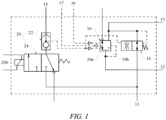
FIG. 1 is a schematic principle diagram of a trailer control valve according to an embodiment of the present invention; -
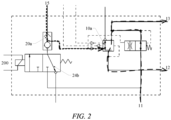
FIG. 2 is a schematic principle diagram of the trailer control valve according to an embodiment of the present invention, showing an air path direction of a traction control valve in a first operating state; -
FIG. 3 is a schematic principle diagram of the trailer control valve according to an embodiment of the present invention, showing an air path direction of the traction control valve in a second operating state; -
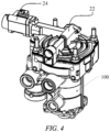
FIG. 4 is a schematic structural diagram of the trailer control valve according to an embodiment of the present invention; -
FIG. 5 is a schematic structural diagram of a first valve member according to an embodiment of the present invention, showing an air path direction when a first valve chamber is opened; -
FIG. 6 is a schematic structural diagram of the first valve member according to an embodiment of the present invention, showing an air path direction when a second valve chamber is opened; and -
FIG. 7 is a schematic structural diagram of a second valve member according to an embodiment of the present invention, showing an air path direction when an air intake valve chamber is opened. - Now exemplary implementations will be described more fully with reference to the accompanying drawings. However, the exemplary implementations can be implemented in many forms and should not be construed as being limited to the implementations set forth herein. On the contrary, these implementations are provided to make the present invention thorough and complete, and to fully convey the concept of the exemplary implementations to those skilled in the art.
- The accompanying drawings are only schematic illustrations of the present invention, and are not necessarily drawn to scale. In the accompanying drawings, the same reference numerals denote the same or similar parts, and thus the repeated description thereof will be omitted. Some block diagrams shown in the accompanying drawings are functional entities, which do not necessarily correspond to physically or logically independent entities. These functional entities may be implemented in the form of software, in one or more hardware modules or integrated circuits, or in different networks and/or processor apparatuses and/or microcontroller apparatuses.
- The terms "first", "second" and similar terms used in the specific description do not denote any order, quantity, or importance, but are merely used to distinguish different components.
- It should be noted that the embodiments in the present invention and features of the various embodiments can be combined with each other without conflict.
-
FIGS. 1 to 3 illustrate a principle of a trailer control valve according to an embodiment of the present invention. An air path direction of a traction control valve in a first operating state is marked out inFIG. 2 , and an air path direction of the traction control valve in a second operating state is marked out inFIG. 3 . With reference toFIGS. 1 to 3 , the trailer control valve according to an embodiment of the present invention includes: - a
control port 15, arelay valve 10, anair inlet 11 and afirst air outlet 12, thecontrol port 15 being connected to acontrol chamber 10a of therelay valve 10, and theair inlet 11 and thefirst air outlet 12 being respectively connected to abrake chamber 10b of therelay valve 10; and - a
traction control valve 20 arranged in a pipeline from thecontrol port 15 to thecontrol chamber 10a and connected to theair inlet 11. - The
traction control valve 20 has a first operating state in which thecontrol port 15 is in communication with thecontrol chamber 10a through afirst channel 20a of thetraction control valve 20; and
thetraction control valve 20 has a second operating state in which theair inlet 11 is in communication with thecontrol chamber 10a through asecond channel 20b of thetraction control valve 20. - In the trailer control valve, the
brake chamber 10b of therelay valve 10 can be opened when thecontrol port 15 outputs a control air pressure to thecontrol chamber 10a of therelay valve 10, such that a brake air pressure of theair inlet 11 is delivered to a trailer control pipeline through thefirst air outlet 12, achieving braking control over a trailer; and the brake air pressure of thefirst air outlet 12 disappears as the control air pressure of thecontrol port 15 disappears. - According to the present invention, an ordinary trailer control valve is integrated with the
traction control valve 20. When thetraction control valve 20 is in the first operating state, thecontrol port 15 is in communication with thecontrol chamber 10a through thefirst channel 20a of thetraction control valve 20, and thecontrol port 15 is connected to a foot brake valve, and at this time, braking control over the trailer is realized according to a braking demand from a driver. When thetraction control valve 20 is in the second operating state, theair inlet 11 is in communication with thecontrol chamber 10a through thesecond channel 20b of thetraction control valve 20. The value of the air pressure output by thefirst air outlet 12 varies with the value of the air pressure from thecontrol chamber 10a. Theair inlet 11 is connected to an air reservoir of a tractor, and the value of air pressure output by the air reservoir is automatically adjusted according to the state of a vehicle. At this time, a braking force of the trailer can be actively controlled according to the state of the vehicle. - Therefore, the trailer control valve according to the present invention can not only perform braking control over the trailer according to the braking demand from the driver, but also realize active control of traction of the trailer according to the state of the vehicle, thus improving the safety of the whole vehicle.
- In some embodiments, the
traction control valve 20 includes: - a
first valve member 22 arranged in the pipeline from thecontrol port 15 to thecontrol chamber 10a, thefirst valve member 22 having a first valve chamber and asecond valve chamber 22b which are alternatively opened, and the first valve chamber being thefirst channel 20a; and - a
second valve member 24 connected to theair inlet 11 and thesecond valve chamber 22b, thesecond valve member 24 having an airintake valve chamber 24a, and the airintake valve chamber 24a and thesecond valve chamber 22b forming thesecond channel 20b. - By means of the first valve chamber and the
second valve chamber 22b of thefirst valve member 22 that are alternatively opened, thecontrol port 15 and theair inlet 11 are alternatively connected to thecontrol chamber 10a of therelay valve 10, such that thetraction control valve 20 enters the first operating state or the second operating state. By means of thesecond valve member 24, the airintake valve chamber 24a thereof is opened when traction control over the trailer is required, such that theair inlet 11 is in communication with thecontrol chamber 10a of therelay valve 10 through thesecond channel 20b; and thesecond channel 20b is closed in case of no need for active control of traction of the trailer. -
FIG. 4 shows a structure of the trailer control valve according to an embodiment of the present invention.FIGS. 5 and 6 show a structure of the first valve member. An air path direction when the first valve chamber is opened is marked out inFIG. 5 , and an air path direction when the second valve chamber is opened is marked out inFIG. 6 . With reference toFIGS. 1 to 6 , in some embodiments: - the
first valve member 22 is a two-way check valve, the two-way check valve having afirst inlet 221 connected to thecontrol port 15, asecond inlet 222 connected to the airintake valve chamber 24a and anoutlet 223 connected to thecontrol chamber 10a; and - a
movable valve core 226 is arranged inside a valve chamber of the two-way check valve, and as thevalve core 226 moves, thefirst inlet 221 is in communication with theoutlet 223 to open the first valve chamber (i.e., thefirst channel 20a), or thesecond inlet 222 is in communication with theoutlet 223 to open thesecond valve chamber 22b. - The
valve core 226 of the two-way check valve can move, under the action of an air pressure from thefirst inlet 221, to open the first valve chamber (i.e., thefirst channel 20a), or move, under the action of an air pressure from thesecond inlet 222, to open thesecond valve chamber 22b, so as to alternatively open thefirst channel 20a and thesecond channel 20b conveniently and accurately. -
FIG. 7 shows a structure of the second valve member, in which an air path direction when the air intake valve chamber is opened is marked out. With reference toFIGS. 1 to 7 , in some embodiments:
thesecond valve member 24 is a two-position three-way solenoid valve having the airintake valve chamber 24a and anexhaust valve chamber 24b, the airintake valve chamber 24a being connected to theair inlet 11 and thesecond valve chamber 22b, and theexhaust valve chamber 24b being connected to thesecond valve chamber 22b. - The air
intake valve chamber 24a of the two-position three-way solenoid valve is opened when traction control over the trailer is required, such that thesecond channel 20b is opened, and the brake air pressure of theair inlet 11 enters thecontrol chamber 10a of therelay valve 10; and thesecond channel 20b is closed when there is no need to actively control the traction of the trailer, such that the air pressure therein is discharged through theexhaust valve chamber 24b. - The
traction control valve 20 is formed by the two-way check valve and the two-position three-way solenoid valve, such that convenient and accurate control over the traction of the trailer is realized. In other embodiments, thetraction control valve 20 may also be switched between the first operating state and the second operating state in the form of a plurality of solenoid valves connected in series or a plurality of check valves combined. - In some embodiments, an operating state switching
control end 200 of thetraction control valve 20 is connected to an electronic control unit ECU. In this way, thetraction control valve 20 can receive an ECU signal of the whole vehicle and open thesecond channel 20b, realizing active braking control over the trailer without involvement of the driver, which in turn realizes the function of traction control over the trailer. - In some embodiments, the
traction control valve 20 is integrated into ahousing 100 of the trailer control valve. In this way, the trailer control valve is highly integrated and is compact in structure. - In some embodiments, the
control port 15 includes at least one of a first control port and a second control port connected to the foot brake valve.FIGS. 1 to 3 show that thecontrol port 15 is a first control port, which is not limited thereto. In other embodiments, thetraction control valve 20 may also be arranged at asecond control port 16, or at both of the first control port and thesecond control port 16. - In addition, the trailer control valve further includes a
third control port 17 for connecting a hand brake valve to thecontrol chamber 10a of therelay valve 10. - In some embodiments, the trailer control valve further includes a
second air outlet 13 connected to theair inlet 11. Thefirst air outlet 12 may be connected to a trailer service braking control pipeline, and thesecond air outlet 13 may be connected to a trailer emergency braking/parking braking control pipeline. - In some embodiments, the trailer control valve further includes a
pneumatic valve 14 arranged in a pipeline from theair inlet 11 to thefirst air outlet 12 and thesecond air outlet 13, a control end of thepneumatic valve 14 being connected to thecontrol chamber 10a. - When the control air pressure is led to the
control chamber 10a, thepneumatic valve 14 is opened, and the brake air pressure of theair inlet 11 may be led to thefirst air outlet 12 and thesecond air outlet 13, thus realizing trailer braking. - An embodiment of the present invention also provides a trailer braking system equipped with a trailer control valve as described in any one of the above embodiments. The trailer braking system is equipped with the trailer control valve mentioned above, which can receive the ECU signal of the whole vehicle while receiving a braking signal from the driver, so as to realize active braking control over the trailer, which in turn achieves the function of traction control over the trailer.
- The above is a further detailed description of the present invention with reference to the specific preferred implementations, and it cannot be considered that the specific implementation of the present invention is limited to these descriptions. For those of ordinary skill in the art of the present invention, several simple deductions or substitutions can be further made without departing from the concept of the present invention, and should be regarded as falling within the scope of protection of the present invention.
Claims (10)
- A trailer control valve, which comprises a control port, a relay valve, an air inlet and a first air outlet, the control port being connected to a control chamber of the relay valve, and the air inlet and the first air outlet being respectively connected to a brake chamber of the relay valve;
characterized by comprising:a traction control valve arranged in a pipeline from the control port to the control chamber and connected to the air inlet; whereinthe traction control valve has a first operating state in which the control port is in communication with the control chamber through a first channel of the traction control valve; andthe traction control valve has a second operating state in which the air inlet is in communication with the control chamber through a second channel of the traction control valve. - The trailer control valve according to claim 1, characterized in that the traction control valve comprises:a first valve member arranged in the pipeline from the control port to the control chamber, the first valve member having a first valve chamber and a second valve chamber which are alternatively opened, and the first valve chamber forming the first channel; anda second valve member connected to the air inlet and the second valve chamber, the second valve member having an air intake valve chamber, and the air intake valve chamber and the second valve chamber forming the second channel.
- The trailer control valve according to claim 2, characterized in that the first valve member is a two-way check valve, the two-way check valve having a first inlet connected to the control port, a second inlet connected to the air intake valve chamber and an outlet connected to the control chamber; and
a movable valve core is arranged inside a valve chamber of the two-way check valve, and as the valve core moves, the first inlet is in communication with the outlet to open the first valve chamber, or the second inlet is in communication with the outlet to open the second valve chamber. - The trailer control valve according to claim 2, characterized in that the second valve member is a two-position three-way solenoid valve having the air intake valve chamber and an exhaust valve chamber, the air intake valve chamber being connected to the air inlet and the second valve chamber, and the exhaust valve chamber being connected to the second valve chamber.
- The trailer control valve according to any one of claims 1-4, characterized in that an operating state switching control end of the traction control valve is connected to an electronic control unit.
- The trailer control valve according to any one of claims 1-4, characterized in that the traction control valve is integrated into a housing of the trailer control valve.
- The trailer control valve according to any one of claims 1-4, characterized in that the control port comprises at least one of a first control port and a second control port connected to a foot brake valve.
- The trailer control valve according to claim 1, characterized by further comprising a second air outlet connected to the air inlet.
- The trailer control valve according to claim 8, characterized by further comprising a pneumatic valve arranged in a pipeline from the air inlet to the first air outlet and the second air outlet, a control end of the pneumatic valve being connected to the control chamber.
- A trailer braking system, characterized by being equipped with a trailer control valve according to any one of claims 1-9.
Applications Claiming Priority (1)
| Application Number | Priority Date | Filing Date | Title |
|---|---|---|---|
| CN202311246795.XA CN117087636B (en) | 2023-09-26 | 2023-09-26 | Trailer control valve and trailer braking system |
Publications (2)
| Publication Number | Publication Date |
|---|---|
| EP4530138A1 true EP4530138A1 (en) | 2025-04-02 |
| EP4530138B1 EP4530138B1 (en) | 2026-02-25 |
Family
ID=88771583
Family Applications (1)
| Application Number | Title | Priority Date | Filing Date |
|---|---|---|---|
| EP24201884.4A Active EP4530138B1 (en) | 2023-09-26 | 2024-09-23 | Trailer control valve and trailer braking system |
Country Status (4)
| Country | Link |
|---|---|
| EP (1) | EP4530138B1 (en) |
| JP (1) | JP2025056771A (en) |
| KR (1) | KR20250046202A (en) |
| CN (1) | CN117087636B (en) |
Citations (3)
| Publication number | Priority date | Publication date | Assignee | Title |
|---|---|---|---|---|
| US7114787B2 (en) * | 2001-07-30 | 2006-10-03 | Knorr-Bremse Systeme Fuer Nutzfahrzeuge Gmbh | Braking system for trailers of utility vehicles |
| CN111907502A (en) * | 2020-07-08 | 2020-11-10 | 东风商用车有限公司 | Tractor air brake hill start auxiliary system |
| DE102020204924A1 (en) * | 2020-04-17 | 2021-10-21 | Volkswagen Aktiengesellschaft | Brake system for a trailer vehicle and trailer vehicle with such a braking system |
Family Cites Families (6)
| Publication number | Priority date | Publication date | Assignee | Title |
|---|---|---|---|---|
| IT1241568B (en) * | 1990-09-24 | 1994-01-18 | Bendix Heavy Vehicle Syst | VALVE ASSEMBLY FOR A PNEUMATIC BRAKING SYSTEM OF A DRIVE, TO CONTROL THE BRAKING OF A TRAILED VEHICLE |
| JP2567510Y2 (en) * | 1992-04-03 | 1998-04-02 | 曙ブレーキ工業株式会社 | Traction control device for multi-axle vehicles |
| JP4255038B2 (en) * | 1997-06-27 | 2009-04-15 | クノールブレムゼ商用車システムジャパン株式会社 | Brake control system with slope start assist device and electromagnetic dual relay valve used in this system |
| US7780245B2 (en) * | 2007-08-13 | 2010-08-24 | Bendix Commercial Vehicle Systems Llc | Valve with integrated quick release |
| KR102382089B1 (en) * | 2017-04-13 | 2022-04-04 | 현대자동차주식회사 | ABS-ASR brake device for vehicles |
| CN220884362U (en) * | 2023-09-26 | 2024-05-03 | 采埃孚商用车系统(青岛)有限公司 | Trailer control valve and trailer braking system |
-
2023
- 2023-09-26 CN CN202311246795.XA patent/CN117087636B/en active Active
-
2024
- 2024-09-23 EP EP24201884.4A patent/EP4530138B1/en active Active
- 2024-09-24 JP JP2024165195A patent/JP2025056771A/en active Pending
- 2024-09-25 KR KR1020240129716A patent/KR20250046202A/en active Pending
Patent Citations (3)
| Publication number | Priority date | Publication date | Assignee | Title |
|---|---|---|---|---|
| US7114787B2 (en) * | 2001-07-30 | 2006-10-03 | Knorr-Bremse Systeme Fuer Nutzfahrzeuge Gmbh | Braking system for trailers of utility vehicles |
| DE102020204924A1 (en) * | 2020-04-17 | 2021-10-21 | Volkswagen Aktiengesellschaft | Brake system for a trailer vehicle and trailer vehicle with such a braking system |
| CN111907502A (en) * | 2020-07-08 | 2020-11-10 | 东风商用车有限公司 | Tractor air brake hill start auxiliary system |
Also Published As
| Publication number | Publication date |
|---|---|
| EP4530138B1 (en) | 2026-02-25 |
| JP2025056771A (en) | 2025-04-08 |
| CN117087636B (en) | 2026-04-14 |
| CN117087636A (en) | 2023-11-21 |
| KR20250046202A (en) | 2025-04-02 |
Similar Documents
| Publication | Publication Date | Title |
|---|---|---|
| US6467854B2 (en) | Braking pressure modulator for a trailer with electronic braking system | |
| US11702054B2 (en) | Redundant braking unit for a braking system and system using same | |
| CN110997434B (en) | Electropneumatic parking brake module with directly controlled valve | |
| US8794718B2 (en) | Valve unit for an electro-pneumatic brake control device for controlling a parking brake | |
| US8297714B2 (en) | Valve unit for a brake control device | |
| US20230083111A1 (en) | Electric parking brake | |
| US20210114572A1 (en) | Heavy duty vehicle redundant braking system | |
| US10946848B2 (en) | Electropneumatic parking brake module for utility vehicles with spring-type parking brakes | |
| US20200086843A1 (en) | Electropneumatic trailer control-valve unit for north america | |
| US12214761B2 (en) | Electropneumatic parking-brake valve unit | |
| US10988126B2 (en) | Solenoid valve assembly for a braking system for a vehicle, braking system for a vehicle, and method for mounting a solenoid valve assembly for a braking system for a vehicle | |
| EP3736188B1 (en) | Locomotive and brake state transition control system therefor | |
| CN107771141A (en) | Automobile-use parking and braking mechanism | |
| CN220884362U (en) | Trailer control valve and trailer braking system | |
| EP4530138B1 (en) | Trailer control valve and trailer braking system | |
| JPH10100891A (en) | 2 conduit trailer brake device | |
| EP1879779B1 (en) | Last car breakaway protection system | |
| CN220764350U (en) | Pneumatic braking system and vehicle | |
| AU2020290396B2 (en) | EBS tractor control line to trailer system to improve transmission timing for an air brake system | |
| US20030184148A1 (en) | Brake system with graduated empty/load | |
| CA1225904A (en) | Gladhand with quick release valve | |
| US20260042434A1 (en) | Electromechanical brake system with pneumatic trailer actuation | |
| EP1188635B1 (en) | Trailer brake valve for a trailer with electronic brake control | |
| US4178044A (en) | Brake mechanism for tractors | |
| SU1008042A1 (en) | Three-axle vehicle brake system |
Legal Events
| Date | Code | Title | Description |
|---|---|---|---|
| PUAI | Public reference made under article 153(3) epc to a published international application that has entered the european phase |
Free format text: ORIGINAL CODE: 0009012 |
|
| STAA | Information on the status of an ep patent application or granted ep patent |
Free format text: STATUS: THE APPLICATION HAS BEEN PUBLISHED |
|
| AK | Designated contracting states |
Kind code of ref document: A1 Designated state(s): AL AT BE BG CH CY CZ DE DK EE ES FI FR GB GR HR HU IE IS IT LI LT LU LV MC ME MK MT NL NO PL PT RO RS SE SI SK SM TR |
|
| STAA | Information on the status of an ep patent application or granted ep patent |
Free format text: STATUS: REQUEST FOR EXAMINATION WAS MADE |
|
| GRAP | Despatch of communication of intention to grant a patent |
Free format text: ORIGINAL CODE: EPIDOSNIGR1 |
|
| STAA | Information on the status of an ep patent application or granted ep patent |
Free format text: STATUS: GRANT OF PATENT IS INTENDED |
|
| 17P | Request for examination filed |
Effective date: 20250929 |
|
| INTG | Intention to grant announced |
Effective date: 20251027 |
|
| RIN1 | Information on inventor provided before grant (corrected) |
Inventor name: JIANG, JOHN Inventor name: LI, JESSE |
|
| GRAS | Grant fee paid |
Free format text: ORIGINAL CODE: EPIDOSNIGR3 |
|
| GRAA | (expected) grant |
Free format text: ORIGINAL CODE: 0009210 |
|
| STAA | Information on the status of an ep patent application or granted ep patent |
Free format text: STATUS: THE PATENT HAS BEEN GRANTED |
|
| AK | Designated contracting states |
Kind code of ref document: B1 Designated state(s): AL AT BE BG CH CY CZ DE DK EE ES FI FR GB GR HR HU IE IS IT LI LT LU LV MC ME MK MT NL NO PL PT RO RS SE SI SK SM TR |
|
| REG | Reference to a national code |
Ref country code: CH Ref legal event code: F10 Free format text: ST27 STATUS EVENT CODE: U-0-0-F10-F00 (AS PROVIDED BY THE NATIONAL OFFICE) Effective date: 20260225 Ref country code: GB Ref legal event code: FG4D |
|
| REG | Reference to a national code |
Ref country code: DE Ref legal event code: R096 Ref document number: 602024002819 Country of ref document: DE |
|
| REG | Reference to a national code |
Ref country code: IE Ref legal event code: FG4D |
|
| P01 | Opt-out of the competence of the unified patent court (upc) registered |
Free format text: CASE NUMBER: UPC_APP_0006698_4530138/2026 Effective date: 20260225 |
|
| REG | Reference to a national code |
Ref country code: NL Ref legal event code: MP Effective date: 20260225 |
|
| PG25 | Lapsed in a contracting state [announced via postgrant information from national office to epo] |
Ref country code: RS Free format text: LAPSE BECAUSE OF FAILURE TO SUBMIT A TRANSLATION OF THE DESCRIPTION OR TO PAY THE FEE WITHIN THE PRESCRIBED TIME-LIMIT Effective date: 20260525 |
|
| PG25 | Lapsed in a contracting state [announced via postgrant information from national office to epo] |
Ref country code: ES Free format text: LAPSE BECAUSE OF FAILURE TO SUBMIT A TRANSLATION OF THE DESCRIPTION OR TO PAY THE FEE WITHIN THE PRESCRIBED TIME-LIMIT Effective date: 20260225 |
|
| PG25 | Lapsed in a contracting state [announced via postgrant information from national office to epo] |
Ref country code: PL Free format text: LAPSE BECAUSE OF FAILURE TO SUBMIT A TRANSLATION OF THE DESCRIPTION OR TO PAY THE FEE WITHIN THE PRESCRIBED TIME-LIMIT Effective date: 20260225 |
|
| PG25 | Lapsed in a contracting state [announced via postgrant information from national office to epo] |
Ref country code: GR Free format text: LAPSE BECAUSE OF FAILURE TO SUBMIT A TRANSLATION OF THE DESCRIPTION OR TO PAY THE FEE WITHIN THE PRESCRIBED TIME-LIMIT Effective date: 20260526 |
|
| REG | Reference to a national code |
Ref country code: LT Ref legal event code: MG9D |
|
| PG25 | Lapsed in a contracting state [announced via postgrant information from national office to epo] |
Ref country code: LT Free format text: LAPSE BECAUSE OF FAILURE TO SUBMIT A TRANSLATION OF THE DESCRIPTION OR TO PAY THE FEE WITHIN THE PRESCRIBED TIME-LIMIT Effective date: 20260225 |
|
| PG25 | Lapsed in a contracting state [announced via postgrant information from national office to epo] |
Ref country code: NO Free format text: LAPSE BECAUSE OF FAILURE TO SUBMIT A TRANSLATION OF THE DESCRIPTION OR TO PAY THE FEE WITHIN THE PRESCRIBED TIME-LIMIT Effective date: 20260525 |
|
| PG25 | Lapsed in a contracting state [announced via postgrant information from national office to epo] |
Ref country code: AT Free format text: LAPSE BECAUSE OF FAILURE TO SUBMIT A TRANSLATION OF THE DESCRIPTION OR TO PAY THE FEE WITHIN THE PRESCRIBED TIME-LIMIT Effective date: 20260225 Ref country code: FI Free format text: LAPSE BECAUSE OF FAILURE TO SUBMIT A TRANSLATION OF THE DESCRIPTION OR TO PAY THE FEE WITHIN THE PRESCRIBED TIME-LIMIT Effective date: 20260225 Ref country code: SE Free format text: LAPSE BECAUSE OF FAILURE TO SUBMIT A TRANSLATION OF THE DESCRIPTION OR TO PAY THE FEE WITHIN THE PRESCRIBED TIME-LIMIT Effective date: 20260225 |
|
| REG | Reference to a national code |
Ref country code: AT Ref legal event code: MK05 Ref document number: 1890519 Country of ref document: AT Kind code of ref document: T Effective date: 20260225 |
|
| PG25 | Lapsed in a contracting state [announced via postgrant information from national office to epo] |
Ref country code: HR Free format text: LAPSE BECAUSE OF FAILURE TO SUBMIT A TRANSLATION OF THE DESCRIPTION OR TO PAY THE FEE WITHIN THE PRESCRIBED TIME-LIMIT Effective date: 20260225 |
|
| PG25 | Lapsed in a contracting state [announced via postgrant information from national office to epo] |
Ref country code: IS Free format text: LAPSE BECAUSE OF FAILURE TO SUBMIT A TRANSLATION OF THE DESCRIPTION OR TO PAY THE FEE WITHIN THE PRESCRIBED TIME-LIMIT Effective date: 20260625 Ref country code: PT Free format text: LAPSE BECAUSE OF FAILURE TO SUBMIT A TRANSLATION OF THE DESCRIPTION OR TO PAY THE FEE WITHIN THE PRESCRIBED TIME-LIMIT Effective date: 20260625 |
|
| PG25 | Lapsed in a contracting state [announced via postgrant information from national office to epo] |
Ref country code: NL Free format text: LAPSE BECAUSE OF FAILURE TO SUBMIT A TRANSLATION OF THE DESCRIPTION OR TO PAY THE FEE WITHIN THE PRESCRIBED TIME-LIMIT Effective date: 20260225 |
|
| PG25 | Lapsed in a contracting state [announced via postgrant information from national office to epo] |
Ref country code: LV Free format text: LAPSE BECAUSE OF FAILURE TO SUBMIT A TRANSLATION OF THE DESCRIPTION OR TO PAY THE FEE WITHIN THE PRESCRIBED TIME-LIMIT Effective date: 20260225 |
|
| PG25 | Lapsed in a contracting state [announced via postgrant information from national office to epo] |
Ref country code: BG Free format text: LAPSE BECAUSE OF FAILURE TO SUBMIT A TRANSLATION OF THE DESCRIPTION OR TO PAY THE FEE WITHIN THE PRESCRIBED TIME-LIMIT Effective date: 20260225 |