EP4530101A1 - Running unit - Google Patents
Running unit Download PDFInfo
- Publication number
- EP4530101A1 EP4530101A1 EP24201702.8A EP24201702A EP4530101A1 EP 4530101 A1 EP4530101 A1 EP 4530101A1 EP 24201702 A EP24201702 A EP 24201702A EP 4530101 A1 EP4530101 A1 EP 4530101A1
- Authority
- EP
- European Patent Office
- Prior art keywords
- rotating
- rockable
- transmission element
- transmission
- elongated
- Prior art date
- Legal status (The legal status is an assumption and is not a legal conclusion. Google has not performed a legal analysis and makes no representation as to the accuracy of the status listed.)
- Pending
Links
Images



Classifications
-
- B—PERFORMING OPERATIONS; TRANSPORTING
- B60—VEHICLES IN GENERAL
- B60G—VEHICLE SUSPENSION ARRANGEMENTS
- B60G3/00—Resilient suspensions for a single wheel
- B60G3/02—Resilient suspensions for a single wheel with a single pivoted arm
- B60G3/12—Resilient suspensions for a single wheel with a single pivoted arm the arm being essentially parallel to the longitudinal axis of the vehicle
- B60G3/14—Resilient suspensions for a single wheel with a single pivoted arm the arm being essentially parallel to the longitudinal axis of the vehicle the arm being rigid
-
- B—PERFORMING OPERATIONS; TRANSPORTING
- B60—VEHICLES IN GENERAL
- B60G—VEHICLE SUSPENSION ARRANGEMENTS
- B60G21/00—Interconnection systems for two or more resiliently-suspended wheels, e.g. for stabilising a vehicle body with respect to acceleration, deceleration or centrifugal forces
- B60G21/02—Interconnection systems for two or more resiliently-suspended wheels, e.g. for stabilising a vehicle body with respect to acceleration, deceleration or centrifugal forces permanently interconnected
- B60G21/04—Interconnection systems for two or more resiliently-suspended wheels, e.g. for stabilising a vehicle body with respect to acceleration, deceleration or centrifugal forces permanently interconnected mechanically
- B60G21/05—Interconnection systems for two or more resiliently-suspended wheels, e.g. for stabilising a vehicle body with respect to acceleration, deceleration or centrifugal forces permanently interconnected mechanically between wheels on the same axle but on different sides of the vehicle, i.e. the left and right wheel suspensions being interconnected
-
- B—PERFORMING OPERATIONS; TRANSPORTING
- B62—LAND VEHICLES FOR TRAVELLING OTHERWISE THAN ON RAILS
- B62K—CYCLES; CYCLE FRAMES; CYCLE STEERING DEVICES; RIDER-OPERATED TERMINAL CONTROLS SPECIALLY ADAPTED FOR CYCLES; CYCLE AXLE SUSPENSIONS; CYCLE SIDECARS, FORECARS, OR THE LIKE
- B62K5/00—Cycles with handlebars, equipped with three or more main road wheels
- B62K5/10—Cycles with handlebars, equipped with three or more main road wheels with means for inwardly inclining the vehicle body on bends
-
- B—PERFORMING OPERATIONS; TRANSPORTING
- B60—VEHICLES IN GENERAL
- B60G—VEHICLE SUSPENSION ARRANGEMENTS
- B60G2200/00—Indexing codes relating to suspension types
- B60G2200/10—Independent suspensions
- B60G2200/13—Independent suspensions with longitudinal arms only
- B60G2200/132—Independent suspensions with longitudinal arms only with a single trailing arm
-
- B—PERFORMING OPERATIONS; TRANSPORTING
- B60—VEHICLES IN GENERAL
- B60G—VEHICLE SUSPENSION ARRANGEMENTS
- B60G2204/00—Indexing codes related to suspensions per se or to auxiliary parts
- B60G2204/40—Auxiliary suspension parts; Adjustment of suspensions
- B60G2204/419—Gears
-
- B—PERFORMING OPERATIONS; TRANSPORTING
- B60—VEHICLES IN GENERAL
- B60G—VEHICLE SUSPENSION ARRANGEMENTS
- B60G2204/00—Indexing codes related to suspensions per se or to auxiliary parts
- B60G2204/80—Interactive suspensions; arrangement affecting more than one suspension unit
- B60G2204/83—Type of interconnection
- B60G2204/8302—Mechanical
- B60G2204/83022—Mechanical using cables, wires, belts or chains
Definitions
- the present invention relates to a running unit that includes a main body, a swing motion transmission connected to the main body, a pair of left and right pivot arms provided to the swing motion transmission so as to be pivotable about a pivot shaft, and wheels provided to the pivot arms respectively.
- a running unit with a main body, a pair of left and right pivot arms pivotable about a pivot shaft, and wheels provided to the pivot arms respectively is known, for example, from Japanese Patent No. 4567813 .
- the running unit of a multi-wheel vehicle 1 described in Japanese Patent No. 4567813 includes a main body (frame 2), a pair of left and right pivot arms (swing arms 4L and 4R) pivotable about a pivot shaft (support shaft part 3A) relative to the main body (frame 2), and wheels (5L and 5R) provided to the pivot arms (swing arms 4L and 4R) respectively.
- the pivot shaft (support shaft part 3A) is provided with substantially fan-shaped tilting members 17L and 17R, whose arcuate portions 21 are each connected to a direction-changing member 19, which is shaped in the form of a balance or a pulley, by a string member 20.
- the tilting members 17L and 17R are thus linked so that, when one of the wheels (5L and 5R) receives a force from the road surface and is pushed up via the pivot shaft (support shaft part 3A) and pivot arms (4L and 4R), the other one of the wheels (5L and 5R) can be pushed down toward the road surface.
- the wheels (5L and 5R) can be tilted flexibly with the vehicle body, while the ground pressure of the wheels (5L and 5R) is maintained uniform.
- the running unit according to, for example, Japanese Patent No. 4567813 is configured to link the pair of left and right wheels via the direction-changing member, tilting members, and string member.
- This is a complex structure with many drive parts, which can cause an increase in the production cost as well as the frequency of maintenance such as grease replenishment.
- the left and right wheels are linked by connecting by means of a string member the direction-changing member, which is shaped in the form of a balance or pulley, and the left and right tilting members.
- This design requires the direction-changing member and tilting members to have a certain size and to be spaced a certain distance apart, which compromises the flexibility of equipment design.
- the present invention solves these problems, an object thereof being to provide a running unit that can reduce the production cost and maintenance frequency, and allow for higher flexibility of equipment design, with a simple structure.
- a running unit which includes: a main body; a swing motion transmission connected to the main body; a pair of left and right pivot arms provided to the swing motion transmission so as to be pivotable about a pivot shaft; and wheels provided to the pivot arms respectively.
- the swing motion transmission includes a first rockable rotating element that rotates in conjunction with a pivoting movement of one of the pivot arms, a second rockable rotating element that rotates in conjunction with a pivoting movement of the other one of the pivot arms, a first rotating transmission element that transmits rotation via the first rockable rotating element and a first elongated transmission element, and a second rotating transmission element that transmits rotation via the second rockable rotating element and a second elongated transmission element.
- the first rotating transmission element and the second rotating transmission element are connected together, with respective rotating shafts thereof being coupled together by a linking shaft.
- the first rockable rotating element and the second rockable rotating element are configured to be able to rotate in conjunction with each other and in opposite directions.
- the swing motion transmission includes a first rockable rotating element that rotates in conjunction with a pivoting movement of one pivot arm, a second rockable rotating element that rotates in conjunction with a pivoting movement of the other pivot arm, a first rotating transmission element that transmits rotation via the first rockable rotating element and a first elongated transmission element, and a second rotating transmission element that transmits rotation via the second rockable rotating element and a second elongated transmission element.
- the first rotating transmission element and the second rotating transmission element are connected together, with respective rotating shafts thereof coupled together by a linking shaft.
- the first rockable rotating element and the second rockable rotating element are configured to rotate in opposite directions in conjunction with each other.
- the swing motion transmission allows the pair of left and right wheels to change their height in accordance with the tilt in the left and right direction of the vehicle body, or the irregularities or slope of the road surface, so that the left and right wheels both reliably stay on the ground, which improves the running stability.
- the pivot shafts and the linking shaft arranged in close proximity to each other allow for a compact configuration for moving the left and right wheels together in their swinging directions, and help improve the degree of freedom in the design of the running unit.
- the first elongated transmission element is a chain with ends, one end thereof being connected to the first rockable rotating element and the other end thereof being connected to the first rotating transmission element.
- the second elongated transmission element is a chain with ends, one end thereof being connected to the second rockable rotating element and the other end thereof being connected to the second rotating transmission element.
- the first rotating transmission element, first rockable rotating element, second rotating transmission element, and second rockable rotating element may be sprockets, so that they can reliably transmit rotation.
- the sprockets may each have teeth only over an arc where the open-ended chain engages, which reduces the overall weight of the swing motion transmission as well as the space the sprockets take up.
- the swing motion transmission includes a third rockable rotating element axially adjacent the first rockable rotating element and rotating therewith, a fourth rockable rotating element axially adjacent the second rockable rotating element and rotating therewith, a third rotating transmission element that transmits rotation via the third rockable rotating element and a third elongated transmission element, and a fourth rotating transmission element that transmits rotation via the fourth rockable rotating element and a fourth elongated transmission element.
- the third rotating transmission element and the fourth rotating transmission element are connected together by a linking shaft.
- the third elongated transmission element is configured to transmit rotation by pulling, in the opposite direction, from the first elongated transmission element
- the fourth elongated transmission element is configured to transmit rotation by pulling, in the opposite direction, from the second elongated transmission element.
- the elongated transmission elements are unlikely to slacken no matter which way each pivot arm moves. For example, even when the main body is picked up so that both wheels are lifted up from the ground, both pivot arms move cooperatively in opposite directions rather than swinging down together.
- the third elongated transmission element is a chain with ends, one end thereof being connected to the third rockable rotating element and the other end thereof being connected to the third rotating transmission element.
- the fourth elongated transmission element is a chain with ends, one end thereof being connected to the fourth rockable rotating element and the other end thereof being connected to the fourth rotating transmission element.
- the third rotating transmission element, third rockable rotating element, fourth rotating transmission element, and fourth rockable rotating element may be sprockets, so that they can reliably transmit rotation.
- the sprockets may each have teeth only over an arc where the open-ended chain engages, which reduces the overall weight of the swing motion transmission as well as the space the sprockets take up.
- a running unit 100 according to one embodiment of the present invention is described below with reference to the drawings.
- main body 110 is depicted as separate left and right parts.
- the left and right parts of the main body 110 are coupled together by other components not shown here, so that the main body 110 is in one piece and the pivot shafts 111 (first pivot shaft 111R and second pivot shaft 111L) and the linking shaft 125 are at fixed positions relative to each other.
- the running unit 100 includes, as shown in FIG. 1 to FIG. 5 , a main body 110, a swing motion transmission 120 connected to the main body 110, a pair of left and right pivot arms 112 (first pivot arm 112R and second pivot arm 112L) provided to the swing motion transmission 120 such as to be pivotable about pivot shafts 111 (first pivot shaft 111R and second pivot shaft 111L), wheels 113 (first wheel 113R and second wheel 113L) connected to the respective pivot arms 112 such as to be rotatable about rotating shafts 114 (first rotating shaft 114R and second rotating shaft 114L).
- the swing motion transmission 120 includes a first rockable sprocket 121 that is a first rockable rotating element connected to the first pivot arm 112R via the first pivot shaft 111R, a second rockable sprocket 122 that is a second rockable rotating element connected to the second pivot arm 112L via the second pivot shaft 111L, a first transmission sprocket 123 that is a first rotating transmission element for transmitting rotation via the first rockable sprocket 121 and a first chain 126 that is a first elongated transmission element, and a second transmission sprocket 124 that is a second rotating transmission element for transmitting rotation via the second rockable sprocket 122 and a second chain 127 that is a second elongated transmission element.
- the first transmission sprocket 123 and second transmission sprocket 124 are connected together by a linking shaft 125 that couples together their rotating shafts.
- the first chain 126 is stretched between the lower sides of the first rockable sprocket 121 and first transmission sprocket 123, one end and the other end of the first chain 126 being fixed to the first rockable sprocket 121 and the first transmission sprocket 123, respectively.
- the second chain 127 is stretched between the lower side of the second rockable sprocket 122 and the upper side of the second transmission sprocket 124, one end and the other end of the second chain 127 being fixed to the second rockable sprocket 122 and the second transmission sprocket 124, respectively.
- the first rockable sprocket 121 and second rockable sprocket 122 are thus linked such as to be rotatable in opposite directions.
- the second rockable sprocket 122 connected to the second pivot arm 112L via the second pivot shaft 111L rotates, too. Since the second chain 127 is wound around the second transmission sprocket 124 and second rockable sprocket 122 in opposite directions, the second transmission sprocket 124 rotates reversely from the second rockable sprocket 122.
- first transmission sprocket 123 and second transmission sprocket 124 are connected together by the linking shaft 125 that couples together their rotating shafts, the first transmission sprocket 123 rotates in the same direction as the second transmission sprocket 124.
- first rockable sprocket 121 rotates in the same direction as the first transmission sprocket 123, and in the reverse direction from the second rockable sprocket 122.
- the first wheel 113R while maintaining contact with the flat surface FG, swings up with the first pivot arm 112R as viewed from the first pivot shaft 111R, so that the left and right wheels 113 make contact with the flat surface FG with their rotating shafts 114 being positioned on a straight line.
- the left and right wheels 113 are configured to swing cooperatively in opposite directions from each other in this way so that, even when one wheel 113 rides up onto a step or the like, the other wheel 113 can stay on the ground, without causing the main body 110 to tilt largely. Thus the running stability can be improved.
- the first wheel 113R and second wheel 113L can both stay on the ground, and thus the running stability can be improved.
- the sprockets may be partly or entirely toothless on the outer circumference as long as they are able to transmit the pulling force exerted by the open-ended first chain 126 and the second chain 127 wound around and fixedly attached to the sprockets at both ends.
- the first chain 126 that is wound around the sprockets in the same direction may be formed as an endless chain and passed around the sprockets.
- a running unit 100b includes, as shown in FIG. 9 , a third rockable sprocket 131 that is a third rockable rotating element axially adjacent the first rockable sprocket 121 to rotate therewith, a fourth rockable sprocket 132 that is a fourth rockable rotating element axially adjacent the second rockable sprocket 122 to rotate therewith, a third transmission sprocket 133 for transmitting rotation via the third rockable sprocket 131 and a third chain 136 that is a third elongated transmission element, and a fourth transmission sprocket 134 for transmitting rotation via the fourth rockable sprocket 132 and a fourth chain 137 that is a fourth elongated transmission element, in addition to the components similar to the first embodiment.
- the first transmission sprocket 123, second transmission sprocket 124, third transmission sprocket 133, and fourth transmission sprocket 134 are connected together by the linking shaft 125 that couples together their rotating shafts.
- the first chain 126 is stretched between the lower sides of the first rockable sprocket 121 and first transmission sprocket 123, one end and the other end of the first chain 126 being fixed to the first rockable sprocket 121 and the first transmission sprocket 123, respectively.
- the second chain 127 is stretched between the lower side of the second rockable sprocket 122 and the upper side of the second transmission sprocket 124, one end and the other end of the second chain 127 being fixed to the second rockable sprocket 122 and the second transmission sprocket 124, respectively.
- the third chain 136 is stretched between the upper sides of the third rockable sprocket 131 and the third transmission sprocket 133, one end and the other end of the third chain 136 being fixed to the third rockable sprocket 131 and the third transmission sprocket 133, respectively.
- the fourth chain 137 is stretched between the upper side of the fourth rockable sprocket 132 and the lower side of the fourth transmission sprocket 134, one end and the other end of the fourth chain 137 being fixed to the fourth rockable sprocket 132 and the fourth transmission sprocket 134, respectively.
- the third rockable sprocket 131 and fourth rockable sprocket 132 are linked such as to be rotatable in opposite directions similarly to the first rockable sprocket 121 and second rockable sprocket 122. Therefore, when the main body 100b is picked up so that both wheels 113 (first wheel 113R and second wheel 113L) are lifted up from the ground, the pivot arms 112 (first pivot arm 112R and second pivot arm 112L) can move in opposite directions rather than swinging down together.
- the running unit according the present invention can be used for various types of vehicles that run on wheels, such as engine- or motor-driven vehicles, human-powered bicycles or cargo-carrying carts.
- the wheels of the running unit can serve as rear wheels of a running vehicle as described in the embodiments above, this configuration is not limiting.
- the running unit may be attached to a running vehicle such as to function as front wheels.
- the elongated transmission element is a chain in the embodiments described above, the elongated transmission element may be a band-like member such as a belt, or a string-like member such as a rope.
Landscapes
- Engineering & Computer Science (AREA)
- Mechanical Engineering (AREA)
- Motorcycle And Bicycle Frame (AREA)
- Devices For Conveying Motion By Means Of Endless Flexible Members (AREA)
- Automatic Cycles, And Cycles In General (AREA)
- Axle Suspensions And Sidecars For Cycles (AREA)
Abstract
Description
- The present invention relates to a running unit that includes a main body, a swing motion transmission connected to the main body, a pair of left and right pivot arms provided to the swing motion transmission so as to be pivotable about a pivot shaft, and wheels provided to the pivot arms respectively.
- Conventionally, a running unit with a main body, a pair of left and right pivot arms pivotable about a pivot shaft, and wheels provided to the pivot arms respectively is known, for example, from
Japanese Patent No. 4567813 - The running unit of a multi-wheel vehicle 1 described in
Japanese Patent No. 4567813 - The tilting members 17L and 17R are thus linked so that, when one of the wheels (5L and 5R) receives a force from the road surface and is pushed up via the pivot shaft (support shaft part 3A) and pivot arms (4L and 4R), the other one of the wheels (5L and 5R) can be pushed down toward the road surface. When the vehicle makes a turn or changes directions, or when running on a laterally inclined road surface, the wheels (5L and 5R) can be tilted flexibly with the vehicle body, while the ground pressure of the wheels (5L and 5R) is maintained uniform.
- The running unit known from, for example, the patent literature mentioned above still has some scope of improvement.
- Namely, the running unit according to, for example,
Japanese Patent No. 4567813 - The left and right wheels are linked by connecting by means of a string member the direction-changing member, which is shaped in the form of a balance or pulley, and the left and right tilting members. This design requires the direction-changing member and tilting members to have a certain size and to be spaced a certain distance apart, which compromises the flexibility of equipment design.
- The present invention solves these problems, an object thereof being to provide a running unit that can reduce the production cost and maintenance frequency, and allow for higher flexibility of equipment design, with a simple structure.
- The above object is achieved by a running unit according to the present invention, which includes: a main body; a swing motion transmission connected to the main body; a pair of left and right pivot arms provided to the swing motion transmission so as to be pivotable about a pivot shaft; and wheels provided to the pivot arms respectively. The swing motion transmission includes a first rockable rotating element that rotates in conjunction with a pivoting movement of one of the pivot arms, a second rockable rotating element that rotates in conjunction with a pivoting movement of the other one of the pivot arms, a first rotating transmission element that transmits rotation via the first rockable rotating element and a first elongated transmission element, and a second rotating transmission element that transmits rotation via the second rockable rotating element and a second elongated transmission element. The first rotating transmission element and the second rotating transmission element are connected together, with respective rotating shafts thereof being coupled together by a linking shaft. The first rockable rotating element and the second rockable rotating element are configured to be able to rotate in conjunction with each other and in opposite directions.
- According to the invention set forth in claim 1 and claim 5, the swing motion transmission includes a first rockable rotating element that rotates in conjunction with a pivoting movement of one pivot arm, a second rockable rotating element that rotates in conjunction with a pivoting movement of the other pivot arm, a first rotating transmission element that transmits rotation via the first rockable rotating element and a first elongated transmission element, and a second rotating transmission element that transmits rotation via the second rockable rotating element and a second elongated transmission element. The first rotating transmission element and the second rotating transmission element are connected together, with respective rotating shafts thereof coupled together by a linking shaft. The first rockable rotating element and the second rockable rotating element are configured to rotate in opposite directions in conjunction with each other. When one of the wheels swings up, for example, due to road surface conditions, the swing motion transmission allows the other pivot arm to swing down in conjunction with the pivoting movement of the one pivot arm, so that the other wheel swings down.
- When, conversely, the other wheel swings up alone, the swing motion transmission allows the one wheel to cooperatively swing down.
- Thus the swing motion transmission allows the pair of left and right wheels to change their height in accordance with the tilt in the left and right direction of the vehicle body, or the irregularities or slope of the road surface, so that the left and right wheels both reliably stay on the ground, which improves the running stability.
- The pivot shafts and the linking shaft arranged in close proximity to each other allow for a compact configuration for moving the left and right wheels together in their swinging directions, and help improve the degree of freedom in the design of the running unit.
- According to the configuration set forth in claim 2, the first elongated transmission element is a chain with ends, one end thereof being connected to the first rockable rotating element and the other end thereof being connected to the first rotating transmission element. The second elongated transmission element is a chain with ends, one end thereof being connected to the second rockable rotating element and the other end thereof being connected to the second rotating transmission element. The first rotating transmission element, first rockable rotating element, second rotating transmission element, and second rockable rotating element may be sprockets, so that they can reliably transmit rotation. The sprockets may each have teeth only over an arc where the open-ended chain engages, which reduces the overall weight of the swing motion transmission as well as the space the sprockets take up.
- According to the configuration set forth in claim 3, the swing motion transmission includes a third rockable rotating element axially adjacent the first rockable rotating element and rotating therewith, a fourth rockable rotating element axially adjacent the second rockable rotating element and rotating therewith, a third rotating transmission element that transmits rotation via the third rockable rotating element and a third elongated transmission element, and a fourth rotating transmission element that transmits rotation via the fourth rockable rotating element and a fourth elongated transmission element. The third rotating transmission element and the fourth rotating transmission element are connected together by a linking shaft. The third elongated transmission element is configured to transmit rotation by pulling, in the opposite direction, from the first elongated transmission element, and the fourth elongated transmission element is configured to transmit rotation by pulling, in the opposite direction, from the second elongated transmission element. The elongated transmission elements are unlikely to slacken no matter which way each pivot arm moves. For example, even when the main body is picked up so that both wheels are lifted up from the ground, both pivot arms move cooperatively in opposite directions rather than swinging down together.
- According to the configuration set forth in claim 4, the third elongated transmission element is a chain with ends, one end thereof being connected to the third rockable rotating element and the other end thereof being connected to the third rotating transmission element. The fourth elongated transmission element is a chain with ends, one end thereof being connected to the fourth rockable rotating element and the other end thereof being connected to the fourth rotating transmission element. The third rotating transmission element, third rockable rotating element, fourth rotating transmission element, and fourth rockable rotating element may be sprockets, so that they can reliably transmit rotation. The sprockets may each have teeth only over an arc where the open-ended chain engages, which reduces the overall weight of the swing motion transmission as well as the space the sprockets take up.
-
-
FIG. 1 is a perspective view of arunning unit 100 according to a first embodiment of the present invention; -
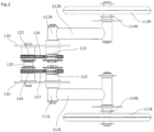
FIG. 2 is a top view of therunning unit 100 according to the first embodiment of the present invention; -
FIG. 3 is a front view of therunning unit 100 according to the first embodiment of the present invention; -
FIG. 4 is a perspective view of therunning unit 100 according to the first embodiment of the present invention seen from below; -
FIG. 5 is an enlarged illustrative view of aswing motion transmission 120 of therunning unit 100 according to the first embodiment of the present invention; -
FIG. 6 is a diagram explaining the operation of the present invention viewed from behind; -
FIG. 7 is an illustrative view of the present invention seen from thesecond wheel 113L side when thesecond wheel 113L swings up; -
FIG. 8 is an illustrative view of the present invention seen from thefirst wheel 113R side when thesecond wheel 113L swings up; and -
FIG. 9 is an enlarged illustrative view of a swing motion transmission 120b of a running unit 100b according to a second embodiment of the present invention. - A running
unit 100 according to one embodiment of the present invention is described below with reference to the drawings. - In the illustration, other components than the
running unit 100 of the running vehicle are not illustrated, so that themain body 110 is depicted as separate left and right parts. In actuality, the left and right parts of themain body 110 are coupled together by other components not shown here, so that themain body 110 is in one piece and the pivot shafts 111 (first pivot shaft 111R andsecond pivot shaft 111L) and the linkingshaft 125 are at fixed positions relative to each other. - The running
unit 100 according to the first embodiment of the present invention includes, as shown inFIG. 1 to FIG. 5 , amain body 110, aswing motion transmission 120 connected to themain body 110, a pair of left and right pivot arms 112 (first pivot arm 112R andsecond pivot arm 112L) provided to theswing motion transmission 120 such as to be pivotable about pivot shafts 111 (first pivot shaft 111R andsecond pivot shaft 111L), wheels 113 (first wheel 113R andsecond wheel 113L) connected to the respective pivot arms 112 such as to be rotatable about rotating shafts 114 (first rotatingshaft 114R and second rotatingshaft 114L). - The
swing motion transmission 120 includes a firstrockable sprocket 121 that is a first rockable rotating element connected to thefirst pivot arm 112R via thefirst pivot shaft 111R, a secondrockable sprocket 122 that is a second rockable rotating element connected to thesecond pivot arm 112L via thesecond pivot shaft 111L, afirst transmission sprocket 123 that is a first rotating transmission element for transmitting rotation via the firstrockable sprocket 121 and afirst chain 126 that is a first elongated transmission element, and asecond transmission sprocket 124 that is a second rotating transmission element for transmitting rotation via the secondrockable sprocket 122 and asecond chain 127 that is a second elongated transmission element. - The
first transmission sprocket 123 andsecond transmission sprocket 124 are connected together by a linkingshaft 125 that couples together their rotating shafts. - The
first chain 126 is stretched between the lower sides of the firstrockable sprocket 121 and first transmission sprocket 123, one end and the other end of thefirst chain 126 being fixed to the firstrockable sprocket 121 and thefirst transmission sprocket 123, respectively. - The
second chain 127 is stretched between the lower side of the secondrockable sprocket 122 and the upper side of the second transmission sprocket 124, one end and the other end of thesecond chain 127 being fixed to the secondrockable sprocket 122 and the second transmission sprocket 124, respectively. - The first
rockable sprocket 121 and secondrockable sprocket 122 are thus linked such as to be rotatable in opposite directions. - Next, the coordinated movements of the
first wheel 113R andsecond wheel 113L of the runningunit 100 according to one embodiment of the present invention are described with reference toFIG. 6 to FIG. 8 . - When the
second wheel 113L of the runningunit 100 running on a flat surface FG rides up onto a raised surface TG as shown inFIG. 7 , thesecond pivot arm 112L swings up about thesecond pivot shaft 111L. - At this time, the second
rockable sprocket 122 connected to thesecond pivot arm 112L via thesecond pivot shaft 111L rotates, too. Since thesecond chain 127 is wound around the second transmission sprocket 124 and secondrockable sprocket 122 in opposite directions, the second transmission sprocket 124 rotates reversely from the secondrockable sprocket 122. - Since the
first transmission sprocket 123 andsecond transmission sprocket 124 are connected together by the linkingshaft 125 that couples together their rotating shafts, thefirst transmission sprocket 123 rotates in the same direction as thesecond transmission sprocket 124. - Since the
first chain 126 is wound around thefirst transmission sprocket 123 andfirst rockable sprocket 121 in the same direction, thefirst rockable sprocket 121 rotates in the same direction as thefirst transmission sprocket 123, and in the reverse direction from thesecond rockable sprocket 122. - This causes the
first pivot arm 112R connected to thefirst rockable sprocket 121 via thefirst pivot shaft 111R to swing down so that thefirst wheel 113R makes contact with the flat surface FG. - As the running vehicle moves on and the
second wheel 113L comes from the top of the raised surface TG down to the flat surface FG, the force that swings thesecond wheel 113L upward is lost, so that thesecond wheel 113L starts to swing down with thesecond pivot arm 112L by the weight of thesecond wheel 113L. - In the meantime, the
first wheel 113R, while maintaining contact with the flat surface FG, swings up with thefirst pivot arm 112R as viewed from thefirst pivot shaft 111R, so that the left and right wheels 113 make contact with the flat surface FG with their rotating shafts 114 being positioned on a straight line. - The left and right wheels 113 are configured to swing cooperatively in opposite directions from each other in this way so that, even when one wheel 113 rides up onto a step or the like, the other wheel 113 can stay on the ground, without causing the
main body 110 to tilt largely. Thus the running stability can be improved. - Needless to say, when the
first wheel 113R swings up alone, thefirst wheel 113R and thesecond wheel 113L move cooperatively and thesecond wheel 113L swings down. - Also, when the running vehicle turns a curve, for example, and the vehicle body tilts, the
first wheel 113R andsecond wheel 113L can both stay on the ground, and thus the running stability can be improved. - The sprockets may be partly or entirely toothless on the outer circumference as long as they are able to transmit the pulling force exerted by the open-ended
first chain 126 and thesecond chain 127 wound around and fixedly attached to the sprockets at both ends. - The
first chain 126 that is wound around the sprockets in the same direction may be formed as an endless chain and passed around the sprockets. - A running unit 100b according to a second embodiment of the present invention includes, as shown in
FIG. 9 , athird rockable sprocket 131 that is a third rockable rotating element axially adjacent thefirst rockable sprocket 121 to rotate therewith, afourth rockable sprocket 132 that is a fourth rockable rotating element axially adjacent thesecond rockable sprocket 122 to rotate therewith, athird transmission sprocket 133 for transmitting rotation via thethird rockable sprocket 131 and athird chain 136 that is a third elongated transmission element, and afourth transmission sprocket 134 for transmitting rotation via thefourth rockable sprocket 132 and afourth chain 137 that is a fourth elongated transmission element, in addition to the components similar to the first embodiment. - The
first transmission sprocket 123,second transmission sprocket 124,third transmission sprocket 133, andfourth transmission sprocket 134 are connected together by the linkingshaft 125 that couples together their rotating shafts. - Similarly to the first embodiment, the
first chain 126 is stretched between the lower sides of thefirst rockable sprocket 121 andfirst transmission sprocket 123, one end and the other end of thefirst chain 126 being fixed to thefirst rockable sprocket 121 and thefirst transmission sprocket 123, respectively. - Similarly to the first embodiment, the
second chain 127 is stretched between the lower side of thesecond rockable sprocket 122 and the upper side of thesecond transmission sprocket 124, one end and the other end of thesecond chain 127 being fixed to thesecond rockable sprocket 122 and thesecond transmission sprocket 124, respectively. - In this embodiment, moreover, the
third chain 136 is stretched between the upper sides of thethird rockable sprocket 131 and thethird transmission sprocket 133, one end and the other end of thethird chain 136 being fixed to thethird rockable sprocket 131 and thethird transmission sprocket 133, respectively. - The
fourth chain 137 is stretched between the upper side of thefourth rockable sprocket 132 and the lower side of thefourth transmission sprocket 134, one end and the other end of thefourth chain 137 being fixed to thefourth rockable sprocket 132 and thefourth transmission sprocket 134, respectively. - Thus the
third rockable sprocket 131 andfourth rockable sprocket 132 are linked such as to be rotatable in opposite directions similarly to thefirst rockable sprocket 121 andsecond rockable sprocket 122. Therefore, when the main body 100b is picked up so that both wheels 113 (first wheel 113R andsecond wheel 113L) are lifted up from the ground, the pivot arms 112 (first pivot arm 112R andsecond pivot arm 112L) can move in opposite directions rather than swinging down together. - While embodiments of the present invention have been described above in detail, the present invention is not limited to the embodiments described above. Various design changes may be made without departing from the scope of the claims set forth in the claims.
- The running unit according the present invention can be used for various types of vehicles that run on wheels, such as engine- or motor-driven vehicles, human-powered bicycles or cargo-carrying carts.
- While the wheels of the running unit can serve as rear wheels of a running vehicle as described in the embodiments above, this configuration is not limiting. For example, the running unit may be attached to a running vehicle such as to function as front wheels.
- While the elongated transmission element is a chain in the embodiments described above, the elongated transmission element may be a band-like member such as a belt, or a string-like member such as a rope.
Claims (5)
- A running unit comprising:a main body;a swing motion transmission provided to the main body;a pair of left and right pivot arms provided to the swing motion transmission so as to be pivotable about a pivot shaft; andwheels provided to the pivot arms respectively,the swing motion transmission including a first rockable rotating element that rotates in conjunction with a pivoting movement of one of the pivot arms, a second rockable rotating element that rotates in conjunction with a pivoting movement of another one of the pivot arms, a first rotating transmission element that transmits rotation via the first rockable rotating element and a first elongated transmission element, and a second rotating transmission element that transmits rotation via the second rockable rotating element and a second elongated transmission element,the first rotating transmission element and the second rotating transmission element being connected together, with respective rotating shafts thereof being coupled together by a linking shaft, andthe first rockable rotating element and the second rockable rotating element being configured to be able to rotate in conjunction with each other and in opposite directions.
- The running unit according to claim 1, whereinthe first elongated transmission element is a chain with ends, one end thereof being connected to the first rockable rotating element and another end thereof being connected to the first rotating transmission element, andthe second elongated transmission element is a chain with ends, one end thereof being connected to the second rockable rotating element and another end thereof being connected to the second rotating transmission element.
- The running unit according to claim 1, wherein the swing motion transmission includesa third rockable rotating element axially adjacent the first rockable rotating element and rotating therewith, a fourth rockable rotating element axially adjacent the second rockable rotating element and rotating therewith,a third rotating transmission element that transmits rotation via the third rockable rotating element and a third elongated transmission element, and a fourth rotating transmission element that transmits rotation via the fourth rockable rotating element and a fourth elongated transmission element,the third rotating transmission element and the fourth rotating transmission element are connected together by a linking shaft,the third elongated transmission element is configured to transmit rotation by pulling, in an opposite direction, from the first elongated transmission element, andthe fourth elongated transmission element being configured to transmit rotation by pulling, in an opposite direction, from the second elongated transmission element.
- The running unit according to claim 3, whereinthe third elongated transmission element is a chain with ends, one end thereof being connected to the third rockable rotating element and another end thereof being connected to the third rotating transmission element, andthe fourth elongated transmission element is a chain with ends, one end thereof being connected to the fourth rockable rotating element and another end thereof being connected to the fourth rotating transmission element.
- A running vehicle comprising a vehicle body, a front running part having a wheel, and a rear running part having a wheel, at least one of the front running part and the rear running part being configured by the running unit according to any one of claims 1 to 4.
Applications Claiming Priority (1)
| Application Number | Priority Date | Filing Date | Title |
|---|---|---|---|
| JP2023163019A JP2025053904A (en) | 2023-09-26 | 2023-09-26 | Travelling unit |
Publications (1)
| Publication Number | Publication Date |
|---|---|
| EP4530101A1 true EP4530101A1 (en) | 2025-04-02 |
Family
ID=92894622
Family Applications (1)
| Application Number | Title | Priority Date | Filing Date |
|---|---|---|---|
| EP24201702.8A Pending EP4530101A1 (en) | 2023-09-26 | 2024-09-20 | Running unit |
Country Status (4)
| Country | Link |
|---|---|
| EP (1) | EP4530101A1 (en) |
| JP (1) | JP2025053904A (en) |
| CN (1) | CN119705048A (en) |
| TW (1) | TW202513384A (en) |
Citations (1)
| Publication number | Priority date | Publication date | Assignee | Title |
|---|---|---|---|---|
| JP4567813B2 (en) | 2009-02-16 | 2010-10-20 | 公也 稼農 | Multi-wheeled vehicle |
-
2023
- 2023-09-26 JP JP2023163019A patent/JP2025053904A/en active Pending
-
2024
- 2024-07-24 CN CN202410997485.XA patent/CN119705048A/en active Pending
- 2024-08-27 TW TW113132110A patent/TW202513384A/en unknown
- 2024-09-20 EP EP24201702.8A patent/EP4530101A1/en active Pending
Patent Citations (2)
| Publication number | Priority date | Publication date | Assignee | Title |
|---|---|---|---|---|
| JP4567813B2 (en) | 2009-02-16 | 2010-10-20 | 公也 稼農 | Multi-wheeled vehicle |
| EP2383176B1 (en) * | 2009-02-16 | 2013-04-17 | Kinya Kanou | Multiple wheel vehicle |
Also Published As
| Publication number | Publication date |
|---|---|
| CN119705048A (en) | 2025-03-28 |
| JP2025053904A (en) | 2025-04-07 |
| TW202513384A (en) | 2025-04-01 |
Similar Documents
| Publication | Publication Date | Title |
|---|---|---|
| EP1516806B1 (en) | Roll control device for rolling type vehicle | |
| CN1083782C (en) | Steering device for steering wheels of a vehicle | |
| JP4684243B2 (en) | Crawler travel device | |
| KR100452033B1 (en) | Triangle crawler device | |
| US4541501A (en) | Articulated tricycle | |
| CN107953937A (en) | A kind of structure-improved of stride combined mobile robot running gear | |
| US6708791B2 (en) | Snow vehicle | |
| US6637758B2 (en) | Camber control suspension | |
| CN102317144A (en) | Multiple wheel vehicle | |
| EP4530101A1 (en) | Running unit | |
| EP0252674A2 (en) | Uneven ground vehicle | |
| CN211223657U (en) | Running gear and unmanned vehicle | |
| US4232753A (en) | Endless track vehicle | |
| US6260648B1 (en) | System for linking a steering rod to a steering gear in a steerable vehicle or a snowmobile | |
| EP4610156A1 (en) | Running unit | |
| EP4470803A1 (en) | Travel unit | |
| JPS63203484A (en) | Attitude holding mechanism for irregular ground traveling vehicle | |
| JP2026019479A (en) | Traveling unit | |
| GB1567774A (en) | Motorcycles | |
| JPH0516839A (en) | 4-wheel type passenger management machine | |
| CN220905157U (en) | Arch waist moving platform | |
| JP2575442Y2 (en) | Double equalizer type crawler traveling device | |
| JPH07101365A (en) | Roll wheel device for crawler | |
| JP2513377Y2 (en) | Tracked vehicle suspension drive | |
| SU596496A1 (en) | Wheel-stepping propelling means for vehicle |
Legal Events
| Date | Code | Title | Description |
|---|---|---|---|
| PUAI | Public reference made under article 153(3) epc to a published international application that has entered the european phase |
Free format text: ORIGINAL CODE: 0009012 |
|
| STAA | Information on the status of an ep patent application or granted ep patent |
Free format text: STATUS: THE APPLICATION HAS BEEN PUBLISHED |
|
| AK | Designated contracting states |
Kind code of ref document: A1 Designated state(s): AL AT BE BG CH CY CZ DE DK EE ES FI FR GB GR HR HU IE IS IT LI LT LU LV MC ME MK MT NL NO PL PT RO RS SE SI SK SM TR |
|
| STAA | Information on the status of an ep patent application or granted ep patent |
Free format text: STATUS: REQUEST FOR EXAMINATION WAS MADE |
|
| 17P | Request for examination filed |
Effective date: 20250505 |
|
| STAA | Information on the status of an ep patent application or granted ep patent |
Free format text: STATUS: EXAMINATION IS IN PROGRESS |
|
| 17Q | First examination report despatched |
Effective date: 20250902 |