EP4530081A1 - Determination device and image forming apparatus - Google Patents
Determination device and image forming apparatus Download PDFInfo
- Publication number
- EP4530081A1 EP4530081A1 EP24155280.1A EP24155280A EP4530081A1 EP 4530081 A1 EP4530081 A1 EP 4530081A1 EP 24155280 A EP24155280 A EP 24155280A EP 4530081 A1 EP4530081 A1 EP 4530081A1
- Authority
- EP
- European Patent Office
- Prior art keywords
- paper
- light
- amount
- light detector
- detector
- Prior art date
- Legal status (The legal status is an assumption and is not a legal conclusion. Google has not performed a legal analysis and makes no representation as to the accuracy of the status listed.)
- Pending
Links
Images




Classifications
-
- B—PERFORMING OPERATIONS; TRANSPORTING
- B41—PRINTING; LINING MACHINES; TYPEWRITERS; STAMPS
- B41J—TYPEWRITERS; SELECTIVE PRINTING MECHANISMS, i.e. MECHANISMS PRINTING OTHERWISE THAN FROM A FORME; CORRECTION OF TYPOGRAPHICAL ERRORS
- B41J11/00—Devices or arrangements of selective printing mechanisms, e.g. ink-jet printers or thermal printers, for supporting or handling copy material in sheet or web form
- B41J11/009—Detecting type of paper, e.g. by automatic reading of a code that is printed on a paper package or on a paper roll or by sensing the grade of translucency of the paper
-
- G—PHYSICS
- G01—MEASURING; TESTING
- G01N—INVESTIGATING OR ANALYSING MATERIALS BY DETERMINING THEIR CHEMICAL OR PHYSICAL PROPERTIES
- G01N21/00—Investigating or analysing materials by the use of optical means, i.e. using sub-millimetre waves, infrared, visible or ultraviolet light
- G01N21/17—Systems in which incident light is modified in accordance with the properties of the material investigated
- G01N21/55—Specular reflectivity
-
- G—PHYSICS
- G01—MEASURING; TESTING
- G01N—INVESTIGATING OR ANALYSING MATERIALS BY DETERMINING THEIR CHEMICAL OR PHYSICAL PROPERTIES
- G01N21/00—Investigating or analysing materials by the use of optical means, i.e. using sub-millimetre waves, infrared, visible or ultraviolet light
- G01N21/17—Systems in which incident light is modified in accordance with the properties of the material investigated
- G01N21/55—Specular reflectivity
- G01N21/57—Measuring gloss
-
- G—PHYSICS
- G03—PHOTOGRAPHY; CINEMATOGRAPHY; ANALOGOUS TECHNIQUES USING WAVES OTHER THAN OPTICAL WAVES; ELECTROGRAPHY; HOLOGRAPHY
- G03G—ELECTROGRAPHY; ELECTROPHOTOGRAPHY; MAGNETOGRAPHY
- G03G15/00—Apparatus for electrographic processes using a charge pattern
- G03G15/50—Machine control of apparatus for electrographic processes using a charge pattern, e.g. regulating differents parts of the machine, multimode copiers, microprocessor control
- G03G15/5029—Machine control of apparatus for electrographic processes using a charge pattern, e.g. regulating differents parts of the machine, multimode copiers, microprocessor control by measuring the copy material characteristics, e.g. weight, thickness
-
- G—PHYSICS
- G03—PHOTOGRAPHY; CINEMATOGRAPHY; ANALOGOUS TECHNIQUES USING WAVES OTHER THAN OPTICAL WAVES; ELECTROGRAPHY; HOLOGRAPHY
- G03G—ELECTROGRAPHY; ELECTROPHOTOGRAPHY; MAGNETOGRAPHY
- G03G2215/00—Apparatus for electrophotographic processes
- G03G2215/00362—Apparatus for electrophotographic processes relating to the copy medium handling
- G03G2215/00535—Stable handling of copy medium
- G03G2215/00611—Detector details, e.g. optical detector
- G03G2215/00616—Optical detector
Definitions
- the present invention relates to a determination device and an image forming apparatus.
- a media sensor device that automatically identifies a type of paper by reading the paper used for printing with a sensor is known.
- An image forming apparatus is controlled based on the type of the paper identified by the media sensor device. For example, an operation related to paper transport of the image forming apparatus, control of a transfer device, a fixing device, or the like is performed according to the type of the paper. Accordingly, printing appropriate for the type of the paper is implemented, and an intended printed matter can be obtained.
- JP2015-215338A discloses a recording medium smoothness detection apparatus that detects smoothness of a surface of a recording medium. JP2015-215338A also discloses that a printing condition of the image forming apparatus is set based on the detected smoothness.
- the paper on which the coating process for suppressing the gloss of the surface of the paper and the paper on which the coating process is not performed can be determined from each other.
- An object of the present invention is to provide a determination device that determines first paper on which a coating process for suppressing gloss of a surface of the paper is performed and second paper on which the coating process is not performed, or an image forming apparatus including the determination device.
- a determination device including a processor that is used for determining first paper on which a coating process for suppressing gloss of a surface of paper is performed and second paper on which the coating process for suppressing the gloss of the surface of the paper is not performed, a light source that irradiates the surface of the paper with light, a first light detector that detects the light reflected on the surface of the paper, and a second light detector that is provided at a position different from the first light detector and detects diffusely reflected light of the light reflected on the surface of the paper, in which the first light detector is located in a direction shifted by a certain angle with respect to a specular reflection direction of the light reflected on the surface of the paper, and the processor is configured to: acquire a light amount ratio that is a ratio of an amount of the light detected by the first light detector to an amount of the light detected by the second light detector, and determine whether the paper is the first paper or the second paper according to a relationship between the light amount ratio and
- an image forming apparatus including the determination device according to any one of the first aspect to the third aspect.
- the determination device in which the second light detector may be located in a normal direction to the surface of the paper.
- the determination device in which the first light detector may be located in a direction shifted by about 20 degrees with respect to the specular reflection direction of the light reflected on the surface of the paper.
- an image forming apparatus including the determination device according to any one of the fifth aspect to the seventh aspect.
- the paper on which the coating process for suppressing the gloss of the surface of the paper is performed and the paper on which the coating process is not performed are determined.
- the diffusely reflected light is detected by the second light detector even in a case where the incidence angle of the light of the light source (the angle other than 0 degrees) is changed.
- the accuracy in determining the first paper and the second paper is improved as compared with a case where the first light detector is not located in a direction shifted by about 20 degrees with respect to the specular reflection direction of the light.
- the fourth aspect or the eighth aspect of the present disclosure it is possible to use the determination results of the first paper and the second paper in the body of the image forming apparatus.
- the light source may be a light emitting diode (LED), a laser diode (LD), a vertical cavity surface emitting laser (VCSEL), or the like.
- LED light emitting diode
- LD laser diode
- VCSEL vertical cavity surface emitting laser
- a light detector may be, for example, a photodiode.
- the determination device may execute the determination process of another paper type at least one of before executing the determination process of the paper type described below or after the execution.
- the image forming apparatus may be an apparatus that performs printing on a recording medium by using a printing method, such as an electrophotographic method, an inkjet method, offset printing, or gravure printing, or the like.
- the image forming apparatus may apply the image forming condition corresponding to the paper determined by the determination device to the apparatus and the part related to the image formation, and execute the printing process on the paper.
- Fig. 1 is a diagram showing a configuration of an image forming apparatus 10 according to the exemplary embodiment.
- Fig. 2 is a functional block diagram of the image forming apparatus 10.
- the image forming apparatus 10 includes a body 12 and a sensor device 16.
- the body 12 of the image forming apparatus 10 is an apparatus that performs the image formation based on image information obtained from a computer (not shown) such as a PC connected to the body 12.
- the body 12 of the image forming apparatus 10 is an electrophotographic printing device.
- the body 12 of the image forming apparatus 10 includes a control device 50, a transport device 52, a transfer device 54, a fixing device 56, and the like.
- the sensor device 16 includes an insertion port 20 into which paper P is inserted.
- the sensor device 16 is a device that detects the property of the paper P inserted into the insertion port 20.
- the sensor device 16 is connected to the body 12 of the image forming apparatus 10 via a cable 40.
- the cable 40 supplies power from the body 12 to the sensor device 16 and transmits the information on the paper detected by the sensor device 16 to the control device 50 of the body 12.
- the sensor device 16 includes a control device 24, a light source 30, and first to third light detectors 31, 32, and 33.
- the control device 24 may include, for example, a microcontroller.
- the light source 30 is an LED.
- Each of the first to third light detectors 31, 32, and 33 is a photodiode.
- the control device 24 controls the light source 30 according to an instruction from a computer (not shown) such as a PC connected to the control device 50 of the body 12 or the body 12 via the cable 40.
- the control device 24 irradiates the paper P with light from the light source 30 and acquires detection values of the first to third light detectors 31, 32, and 33.
- the control device 24 transmits each acquired detection value to the control device 50 of the body 12.
- the control device 50 of the body 12 determines the type of the paper P based on each detection value from the control device 24 and a threshold value stored in advance in a storage device in the control device 50.
- the sensor device 16 and the control device 50 of the body 12 function as a paper type determination device 14.
- image information input from a computer such as a PC connected to the body 12 is stored in the storage device in the control device 50.
- the user sets the paper P in the insertion port 20 of the sensor device 16, determines the type of the paper P, and then sets the paper P in a paper feed cassette of the body 12.
- the control device 50 of the body 12 determines the type of the paper P based on the information transmitted from the sensor device 16.
- the control device 50 stores image forming conditions for each type of the paper P.
- the image forming condition is, for example, a condition related to the control of the transport device 52, the transfer device 54, the fixing device 56, and the like.
- the control device 50 feeds the paper P in the paper feeding cassette and performs the printing process according to the image information.
- the control device 50 executes the printing process on the paper P by applying the image forming condition associated with the determined paper P to at least one of the transport device 52, the transfer device 54, or the fixing device 56.
- the secondary transfer voltage as an example of the image forming condition, is controlled according to the determined type of paper.
- the determination device 14 has a function of determining the matte coated paper and the plain paper.
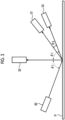
- Fig. 3 is a diagram schematically showing a configuration of the sensor device 16. As described above, the sensor device 16 includes the light source 30 and the first to third light detectors 31, 32, and 33.
- the light source 30 emits light with an incidence angle ⁇ 1.
- ⁇ 1 is 70 degrees. Note that ⁇ 1 may be changed as appropriate.
- the first light detector 31 is located in a direction shifted by a certain angle ⁇ 2 with respect to a specular reflection direction of the light of the light source 30 reflected on the surface of the paper P.
- the third light detector 33 is located in the specular reflection direction of the light of the light source 30.
- ⁇ 2 is 20 degrees.
- the second light detector 32 is located in the normal direction with respect to the surface of the paper P.
- the second light detector 32 detects the diffusely reflected light of the light reflected on the surface of the paper P.
- the light source 30 and the first and second light detectors 31 and 32 are used.
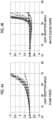
- Fig. 4A is a diagram showing a value obtained by dividing the amount of received light according to a light reception angle of plain paper by the amount of light at the light reception angle of 0 degrees (light amount ratio) in a case where an incidence angle of light is 70 degrees
- Fig. 4B is a diagram showing a value obtained by dividing the amount of received light according to a light reception angle of matte coated paper by the amount of light at the light reception angle of 0 degrees (light amount ratio) in a case where an incidence angle of light is 70 degrees.
- the light reception angle is represented by a negative value of an inclination angle with respect to the light source 30 side, with the normal direction with respect to the surface of the paper P being 0 degrees, and is represented by a positive value of an inclination angle with respect to the specular reflection direction side.
- the light reception angle of 70 degrees is the specular reflection direction.
- Each of a plurality of lines in Figs. 4A and 4B shows the result of one type of paper. That is, a plurality of lines in Fig. 4A show the results of a plurality of types of plain paper, and a plurality of lines in Fig. 4B show the results of a plurality of types of matte coated paper.
- a difference in the amount of received light between the plain paper and the matte coated paper is well shown near the light reception angle of 50 degrees, which is shifted by about 20 degrees from the specular reflection direction (light reception angle of 70 degrees).
- the light reception angle of 50 degrees a relatively high amount of received light is obtained in the case of the plain paper, while a relatively low amount of received light close to the amount of received light at the light reception angle of 0 degrees is obtained in the case of the matte coated paper. Therefore, by acquiring the amount of light at a position shifted by about 20 degrees from the specular reflection direction, it is possible to determine the matte coated paper and the plain paper based on the amount of light. Based on this principle, the paper is determined in the present exemplary embodiment.
- the light source 30 emits the light with an incidence angle of 70 degrees.
- the first light detector 31 is located in a direction shifted by 20 degrees with respect to the specular reflection direction of the light of the light source 30 (light reception angle of 70 degrees), that is, in a direction of a light reception angle of 50 degrees.
- the second light detector 32 is located in a direction of a light reception angle of 0 degrees.
- the first light detector 31 may be located, for example, in a direction shifted by an angle of 20 degrees or an angle close to 20 degrees (about 20 degrees) with respect to the specular reflection direction of the light. Accordingly, it can be expected that the matte coated paper and the plain paper can be determined with relatively high accuracy.
- the position of the first light detector 31 is not limited to the direction.
- the first light detector 31 may be provided at a position where the reflected light of a higher light amount is received in a case where the paper P is the plain paper as compared to a case where the paper P is the matte coated paper.
- the first light detector 31 may be located on the normal direction side with respect to the specular reflection direction of the light (the direction in which the third light detector 33 is located) as shown in Fig. 3 , or may be located on the paper P side with respect to the specular reflection direction of the light.
- the second light detector 32 is located in the normal direction with respect to the surface of the paper P.
- the position of the second light detector 32 is not limited to the direction.
- the second light detector 32 may be provided at a position where the second light detector 32 can detect the amount of light of the diffusely reflected light from the paper P.
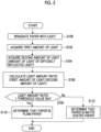
- Fig. 5 is a flowchart showing a determination process of the matte coated paper and the plain paper.
- the control device 24 of the sensor device 16 irradiates the paper P with light from the light source 30.
- the control device 24 acquires a detection value of the first light detector 31 as the first amount of light.
- the control device 24 acquires a detection value of the second light detector 32 as the second amount of light.
- the control device 24 transmits the first amount of light and the second amount of light to the body 12 of the image forming apparatus 10.
- the control device 50 of the body 12 receives the first amount of light and the second amount of light.
- Step S108 the control device 50 confirms whether or not the light amount ratio is equal to or greater than a predetermined threshold value Rth stored in the storage device of the control device 50.
- Step S108 the control device 50 determines that the paper P is plain paper in Step S110.
- Step S110 the control device 50 determines that the paper P is matte coated paper in Step S112.
- the light amount ratio is obtained by using the second amount of light as a denominator and the first amount of light as a numerator.
- the control device 50 determines that the paper P is the plain paper, and otherwise, determines that the paper P is the matte coated paper.
- Step S208 the control device 50 confirms whether or not the light amount difference is equal to or greater than a predetermined threshold value Dth stored in the storage device of the control device 50.
- Step S208 the control device 50 determines that the paper P is plain paper in Step S210.
- the control device 50 determines that the paper P is matte coated paper in Step S212.
- the matte coated paper and the plain paper are also determined.
- the light amount difference is obtained by subtracting the second amount of light from the first amount of light.
- the control device 50 determines that the paper P is the plain paper, and otherwise, determines that the paper P is the matte coated paper.
- the matte coated paper and the plain paper are determined from the first amount of light and the second amount of light.
- the matte coated paper and the plain paper may be determined without using the second amount of light.
- the control device 50 may determine that the paper P is the plain paper, and otherwise, determine that the paper P is the matte coated paper.
- the control device of the above-described exemplary embodiment may be configured by using a computer.
- the control device may be constructed as, for example, a single computer or a system consisting of a plurality of computers that cooperate with each other. As shown as an example in Fig.
- a computer which is the base of the control device, has a circuit configuration in which a processor 1002, a memory (main storage device) 1004 such as a random access memory (RAM), a controller that controls an auxiliary storage device 1006 that is a non-volatile storage device such as a flash memory, a solid state drive (SSD), or a hard disk (HDD), an interface with various input and output devices 1008, a network interface 1010 that performs control for connection with a network, and the like are connected via a data transmission path such as a bus 1012.
- a program in which the contents of the processes are described is installed in the computer via a network or the like, and stored in the auxiliary storage device 1006.
- the control device of the present exemplary embodiment is configured by executing the program which is stored in the auxiliary storage device 1006 by the processor 1002 using the memory 1004.
- the program described above can be provided via a network such as the Internet and provided being stored in a computer-readable recording medium such as an optical disk or a USB memory.
- processor refers to hardware in a broad sense.
- Examples of the processor include general processors (e.g., CPU: Central Processing Unit) and dedicated processors (e.g., GPU: Graphics Processing Unit, ASIC: Application Specific Integrated Circuit, FPGA: Field Programmable Gate Array, and programmable logic device).
- the paper on which the coating process for suppressing the gloss of the surface of the paper is performed and the paper on which the coating process is not performed are determined.
- the diffusely reflected light is detected by the second light detector even in a case where the incidence angle of the light of the light source (the angle other than 0 degrees) is changed.
- the accuracy in determining the first paper and the second paper is improved as compared with a case where the first light detector is not located in a direction shifted by about 20 degrees with respect to the specular reflection direction of the light.
Landscapes
- Physics & Mathematics (AREA)
- General Physics & Mathematics (AREA)
- General Health & Medical Sciences (AREA)
- Chemical & Material Sciences (AREA)
- Analytical Chemistry (AREA)
- Biochemistry (AREA)
- Life Sciences & Earth Sciences (AREA)
- Health & Medical Sciences (AREA)
- Immunology (AREA)
- Pathology (AREA)
- Engineering & Computer Science (AREA)
- Microelectronics & Electronic Packaging (AREA)
- Investigating Or Analysing Materials By Optical Means (AREA)
- Control Or Security For Electrophotography (AREA)
- Investigating Materials By The Use Of Optical Means Adapted For Particular Applications (AREA)
Abstract
A determination device includes a processor that is used for determining first paper on which a coating process for suppressing gloss of a surface of paper is performed and second paper on which the coating process for suppressing the gloss of the surface of the paper is not performed, a light source that irradiates the surface of the paper with light, a first light detector that detects the light reflected on the surface of the paper, and a second light detector that is provided at a position different from the first light detector and detects diffusely reflected light of the light reflected on the surface of the paper, in which the first light detector is located in a direction shifted by a certain angle with respect to a specular reflection direction of the light reflected on the surface of the paper, and the processor is configured to: acquire a light amount ratio that is a ratio of an amount of the light detected by the first light detector to an amount of the light detected by the second light detector; and determine whether the paper is the first paper or the second paper according to a relationship between the light amount ratio and a predetermined threshold value.
Description
- The present invention relates to a determination device and an image forming apparatus.
- A media sensor device that automatically identifies a type of paper by reading the paper used for printing with a sensor is known. An image forming apparatus is controlled based on the type of the paper identified by the media sensor device. For example, an operation related to paper transport of the image forming apparatus, control of a transfer device, a fixing device, or the like is performed according to the type of the paper. Accordingly, printing appropriate for the type of the paper is implemented, and an intended printed matter can be obtained.
-
JP2015-215338A JP2015-215338A - It is required that the paper on which the coating process for suppressing the gloss of the surface of the paper and the paper on which the coating process is not performed can be determined from each other.
- An object of the present invention is to provide a determination device that determines first paper on which a coating process for suppressing gloss of a surface of the paper is performed and second paper on which the coating process is not performed, or an image forming apparatus including the determination device.
- According to a first aspect of the present disclosure, there is provided a determination device including a processor that is used for determining first paper on which a coating process for suppressing gloss of a surface of paper is performed and second paper on which the coating process for suppressing the gloss of the surface of the paper is not performed, a light source that irradiates the surface of the paper with light, a first light detector that detects the light reflected on the surface of the paper, and a second light detector that is provided at a position different from the first light detector and detects diffusely reflected light of the light reflected on the surface of the paper, in which the first light detector is located in a direction shifted by a certain angle with respect to a specular reflection direction of the light reflected on the surface of the paper, and the processor is configured to: acquire a light amount ratio that is a ratio of an amount of the light detected by the first light detector to an amount of the light detected by the second light detector, and determine whether the paper is the first paper or the second paper according to a relationship between the light amount ratio and a predetermined threshold value.
- According to a second aspect of the present disclosure, there is provided the determination device according to the first aspect, in which the second light detector may be located in a normal direction to the surface of the paper.
- According to a third aspect of the present disclosure, there is provided the determination device according to the first aspect or the second aspect, in which the first light detector may be located in a direction shifted by about 20 degrees with respect to the specular reflection direction of the light reflected on the surface of the paper.
- According to a fourth aspect of the present disclosure, there is provided an image forming apparatus including the determination device according to any one of the first aspect to the third aspect.
- According to a fifth aspect of the present disclosure, there is provided a determination device including a processor that is used for determining first paper on which a coating process for suppressing gloss of a surface of paper is performed and second paper on which the coating process for suppressing the gloss of the surface of the paper is not performed, a light source that irradiates the surface of the paper with light, a first light detector that detects the light reflected on the surface of the paper, and a second light detector that is provided at a position different from the first light detector and detects diffusely reflected light of the light reflected on the surface of the paper, in which the first light detector is located in a direction shifted by a certain angle with respect to a specular reflection direction of the light reflected on the surface of the paper, and the processor is configured to: acquire a light amount difference that is a difference between an amount of the light detected by the first light detector and an amount of the light detected by the second light detector, and determine whether the paper is the first paper or the second paper according to a relationship between the light amount difference and a predetermined threshold value.
- According to a sixth aspect of the present disclosure, there is provided the determination device according to the fifth aspect, in which the second light detector may be located in a normal direction to the surface of the paper.
- According to a seventh aspect of the present disclosure, there is provided the determination device according to the fifth aspect or the sixth aspect, in which the first light detector may be located in a direction shifted by about 20 degrees with respect to the specular reflection direction of the light reflected on the surface of the paper.
- According to an eighth aspect of the present disclosure, there is provided an image forming apparatus including the determination device according to any one of the fifth aspect to the seventh aspect.
- According to the first aspect or the fifth aspect of the present disclosure, the paper on which the coating process for suppressing the gloss of the surface of the paper is performed and the paper on which the coating process is not performed are determined.
- According to the second aspect or the sixth aspect of the present disclosure, the diffusely reflected light is detected by the second light detector even in a case where the incidence angle of the light of the light source (the angle other than 0 degrees) is changed.
- According to the third aspect or the seventh aspect of the present disclosure, the accuracy in determining the first paper and the second paper is improved as compared with a case where the first light detector is not located in a direction shifted by about 20 degrees with respect to the specular reflection direction of the light.
- According to the fourth aspect or the eighth aspect of the present disclosure, it is possible to use the determination results of the first paper and the second paper in the body of the image forming apparatus.
- Exemplary embodiment(s) of the present invention will be described in detail based on the following figures, wherein:
-
Fig. 1 is a diagram showing a configuration of an image forming apparatus according to an exemplary embodiment; -
Fig. 2 is a functional block diagram showing the image forming apparatus according to the exemplary embodiment; -
Fig. 3 is a diagram showing a configuration of a sensor device according to the exemplary embodiment; -
Fig. 4A is a diagram showing a value obtained by dividing the amount of received light according to a light reception angle of plain paper by the amount of light at the light reception angle of 0 degrees (light amount ratio) in a case where an incidence angle of light is 70 degrees, andFig. 4B is a diagram showing a value obtained by dividing the amount of received light according to a light reception angle of matte coated paper by the amount of light at the light reception angle of 0 degrees (light amount ratio) in a case where an incidence angle of light is 70 degrees; -
Fig. 5 is a flowchart showing a determination process of matte coated paper and plain paper; -
Fig. 6 is a flowchart showing another determination process of the matte coated paper and the plain paper; and -
Fig. 7 is a diagram showing an example of a hardware configuration of a computer. - Hereinafter, exemplary embodiments of the present invention will be described in detail with reference to accompanying drawings. Configurations described below are examples for description and can be changed as appropriate. In addition, in a case where a plurality of exemplary embodiments, modification examples, or the like are included in the following, characteristic portions thereof are assumed from the beginning to be combined as appropriate and used. Identical or similar elements are designated by identical reference numerals in all drawings, and duplicate description is omitted.
- Hereinafter, a determination device that determines first paper on which a coating process for suppressing gloss of a surface of the paper is performed and second paper on which the coating process is not performed, or an image forming apparatus including the determination device will be described.
- As an example, the first paper on which the coating process for suppressing the gloss of the surface of the paper is performed may be the matte coated paper or paper equivalent thereto. The second paper on which the coating process for suppressing the gloss of the surface of the paper is not performed may be, for example, the plain paper or paper equivalent thereto.
- As an example, the light source may be a light emitting diode (LED), a laser diode (LD), a vertical cavity surface emitting laser (VCSEL), or the like.
- A light detector may be, for example, a photodiode.
- As an example, the determination device may be configured with only a sensor device separated from a body of the image forming apparatus, or may be configured by combining the sensor device with the body of the image forming apparatus. In addition, the determination device may be provided in a paper transport path of the image forming apparatus or the like.
- The determination device may execute the determination process of another paper type at least one of before executing the determination process of the paper type described below or after the execution.
- As an example, the image forming apparatus may be an apparatus that performs printing on a recording medium by using a printing method, such as an electrophotographic method, an inkjet method, offset printing, or gravure printing, or the like. The image forming apparatus may apply the image forming condition corresponding to the paper determined by the determination device to the apparatus and the part related to the image formation, and execute the printing process on the paper.
- Hereinafter, an exemplary embodiment in which matte coated paper as paper on which the coating process for suppressing gloss of the surface of the paper is performed and plain paper as paper on which the coating process is not performed are determined will be described.
-
Fig. 1 is a diagram showing a configuration of animage forming apparatus 10 according to the exemplary embodiment.Fig. 2 is a functional block diagram of theimage forming apparatus 10. Theimage forming apparatus 10 includes abody 12 and asensor device 16. - The
body 12 of theimage forming apparatus 10 is an apparatus that performs the image formation based on image information obtained from a computer (not shown) such as a PC connected to thebody 12. In the present exemplary embodiment, thebody 12 of theimage forming apparatus 10 is an electrophotographic printing device. Thebody 12 of theimage forming apparatus 10 includes acontrol device 50, atransport device 52, atransfer device 54, afixing device 56, and the like. - As shown in
Fig. 1 , thesensor device 16 includes aninsertion port 20 into which paper P is inserted. Thesensor device 16 is a device that detects the property of the paper P inserted into theinsertion port 20. Thesensor device 16 is connected to thebody 12 of theimage forming apparatus 10 via acable 40. Thecable 40 supplies power from thebody 12 to thesensor device 16 and transmits the information on the paper detected by thesensor device 16 to thecontrol device 50 of thebody 12. - As shown in
Fig. 2 , thesensor device 16 includes acontrol device 24, alight source 30, and first tothird light detectors control device 24 may include, for example, a microcontroller. Thelight source 30 is an LED. Each of the first to thirdlight detectors - The
control device 24 controls thelight source 30 according to an instruction from a computer (not shown) such as a PC connected to thecontrol device 50 of thebody 12 or thebody 12 via thecable 40. Thecontrol device 24 irradiates the paper P with light from thelight source 30 and acquires detection values of the first to thirdlight detectors control device 24 transmits each acquired detection value to thecontrol device 50 of thebody 12. Thecontrol device 50 of thebody 12 determines the type of the paper P based on each detection value from thecontrol device 24 and a threshold value stored in advance in a storage device in thecontrol device 50. As described above, thesensor device 16 and thecontrol device 50 of thebody 12 function as a papertype determination device 14. - An example of an operation of forming an image by the
image forming apparatus 10 will be described. First, image information input from a computer such as a PC connected to thebody 12 is stored in the storage device in thecontrol device 50. The user sets the paper P in theinsertion port 20 of thesensor device 16, determines the type of the paper P, and then sets the paper P in a paper feed cassette of thebody 12. - As described above, the
control device 50 of thebody 12 determines the type of the paper P based on the information transmitted from thesensor device 16. Thecontrol device 50 stores image forming conditions for each type of the paper P. The image forming condition is, for example, a condition related to the control of thetransport device 52, thetransfer device 54, the fixingdevice 56, and the like. Thecontrol device 50 feeds the paper P in the paper feeding cassette and performs the printing process according to the image information. In this case, thecontrol device 50 executes the printing process on the paper P by applying the image forming condition associated with the determined paper P to at least one of thetransport device 52, thetransfer device 54, or the fixingdevice 56. For example, in thetransfer device 54, the secondary transfer voltage, as an example of the image forming condition, is controlled according to the determined type of paper. - Next, the determination of the matte coated paper and the plain paper will be specifically described. The
determination device 14 has a function of determining the matte coated paper and the plain paper.Fig. 3 is a diagram schematically showing a configuration of thesensor device 16. As described above, thesensor device 16 includes thelight source 30 and the first to thirdlight detectors - The
light source 30 emits light with an incidence angle θ1. In the present exemplary embodiment, θ1 is 70 degrees. Note that θ1 may be changed as appropriate. - The
first light detector 31 is located in a direction shifted by a certain angle θ2 with respect to a specular reflection direction of the light of thelight source 30 reflected on the surface of the paper P. The thirdlight detector 33 is located in the specular reflection direction of the light of thelight source 30. In the present exemplary embodiment, θ2 is 20 degrees. - The second
light detector 32 is located in the normal direction with respect to the surface of the paper P. The secondlight detector 32 detects the diffusely reflected light of the light reflected on the surface of the paper P. In the determination of the matte coated paper and the plain paper, thelight source 30 and the first and secondlight detectors - Here, a principle of a method of determining the matte coated paper and the plain paper will be described.
Fig. 4A is a diagram showing a value obtained by dividing the amount of received light according to a light reception angle of plain paper by the amount of light at the light reception angle of 0 degrees (light amount ratio) in a case where an incidence angle of light is 70 degrees, andFig. 4B is a diagram showing a value obtained by dividing the amount of received light according to a light reception angle of matte coated paper by the amount of light at the light reception angle of 0 degrees (light amount ratio) in a case where an incidence angle of light is 70 degrees. The horizontal axis of the graphs inFigs. 4A and 4B is the light reception angle, and the vertical axis thereof is the light amount ratio. The light reception angle is represented by a negative value of an inclination angle with respect to thelight source 30 side, with the normal direction with respect to the surface of the paper P being 0 degrees, and is represented by a positive value of an inclination angle with respect to the specular reflection direction side. InFigs. 4A and 4B , the light reception angle of 70 degrees is the specular reflection direction. Each of a plurality of lines inFigs. 4A and 4B shows the result of one type of paper. That is, a plurality of lines inFig. 4A show the results of a plurality of types of plain paper, and a plurality of lines inFig. 4B show the results of a plurality of types of matte coated paper. - As shown in
Figs. 4A and 4B , a difference in the amount of received light between the plain paper and the matte coated paper is well shown near the light reception angle of 50 degrees, which is shifted by about 20 degrees from the specular reflection direction (light reception angle of 70 degrees). Around the light reception angle of 50 degrees, a relatively high amount of received light is obtained in the case of the plain paper, while a relatively low amount of received light close to the amount of received light at the light reception angle of 0 degrees is obtained in the case of the matte coated paper. Therefore, by acquiring the amount of light at a position shifted by about 20 degrees from the specular reflection direction, it is possible to determine the matte coated paper and the plain paper based on the amount of light. Based on this principle, the paper is determined in the present exemplary embodiment. - As described with reference to
Fig. 3 , thelight source 30 emits the light with an incidence angle of 70 degrees. Thefirst light detector 31 is located in a direction shifted by 20 degrees with respect to the specular reflection direction of the light of the light source 30 (light reception angle of 70 degrees), that is, in a direction of a light reception angle of 50 degrees. In addition, the secondlight detector 32 is located in a direction of a light reception angle of 0 degrees. - The
first light detector 31 may be located, for example, in a direction shifted by an angle of 20 degrees or an angle close to 20 degrees (about 20 degrees) with respect to the specular reflection direction of the light. Accordingly, it can be expected that the matte coated paper and the plain paper can be determined with relatively high accuracy. However, the position of thefirst light detector 31 is not limited to the direction. Thefirst light detector 31 may be provided at a position where the reflected light of a higher light amount is received in a case where the paper P is the plain paper as compared to a case where the paper P is the matte coated paper. In addition, thefirst light detector 31 may be located on the normal direction side with respect to the specular reflection direction of the light (the direction in which the thirdlight detector 33 is located) as shown inFig. 3 , or may be located on the paper P side with respect to the specular reflection direction of the light. - In addition, as described above, the second
light detector 32 is located in the normal direction with respect to the surface of the paper P. However, the position of the secondlight detector 32 is not limited to the direction. The secondlight detector 32 may be provided at a position where the secondlight detector 32 can detect the amount of light of the diffusely reflected light from the paper P. -
Fig. 5 is a flowchart showing a determination process of the matte coated paper and the plain paper. In Step S100, thecontrol device 24 of thesensor device 16 irradiates the paper P with light from thelight source 30. In Step S102, thecontrol device 24 acquires a detection value of thefirst light detector 31 as the first amount of light. In Step S104, thecontrol device 24 acquires a detection value of the secondlight detector 32 as the second amount of light. Thecontrol device 24 transmits the first amount of light and the second amount of light to thebody 12 of theimage forming apparatus 10. Thecontrol device 50 of thebody 12 receives the first amount of light and the second amount of light. - In Step S106, the
control device 50 of thebody 12 calculates a light amount ratio (= first amount of light/second amount of light) by dividing the first amount of light by the second amount of light. Next, in Step S108, thecontrol device 50 confirms whether or not the light amount ratio is equal to or greater than a predetermined threshold value Rth stored in the storage device of thecontrol device 50. - In a case of Yes in Step S108, the
control device 50 determines that the paper P is plain paper in Step S110. On the other hand, in a case of No in Step S108, thecontrol device 50 determines that the paper P is matte coated paper in Step S112. - According to the exemplary embodiment described above, the matte coated paper and the plain paper are determined.
- In Step S106 of
Fig. 5 , the light amount ratio is obtained by using the second amount of light as a denominator and the first amount of light as a numerator. However, the light amount ratio may be obtained by using the first amount of light as a denominator and the second amount of light as a numerator (light amount ratio = second amount of light/first amount of light). In this case, in Step S108, in a case where the light amount ratio is equal to or less than the threshold value, thecontrol device 50 determines that the paper P is the plain paper, and otherwise, determines that the paper P is the matte coated paper. - Next, another determination process of the matte coated paper and the plain paper will be described.
Fig. 6 is a flowchart showing the other determination process of the matte coated paper and the plain paper Steps S200 to S204 inFig. 6 are the same processes as Steps S100 to S104 inFig. 5 . Steps S206 and subsequent steps inFig. 6 are different from the flowchart inFig. 5 . - In Step S206, the
control device 50 of thebody 12 calculates a light amount difference (= first amount of light - second amount of light) by subtracting the second amount of light from the first amount of light. Next, in Step S208, thecontrol device 50 confirms whether or not the light amount difference is equal to or greater than a predetermined threshold value Dth stored in the storage device of thecontrol device 50. - In a case of Yes in Step S208, the
control device 50 determines that the paper P is plain paper in Step S210. On the other hand, in a case of No in Step S208, thecontrol device 50 determines that the paper P is matte coated paper in Step S212. - In the other exemplary embodiment described above, the matte coated paper and the plain paper are also determined.
- In Step S206 of
Fig. 6 , the light amount difference is obtained by subtracting the second amount of light from the first amount of light. However, the light amount difference may be obtained by subtracting the first amount of light from the second amount of light (light amount difference = second amount of light - first amount of light). In this case, in Step S208, in a case where the light amount difference is equal to or less than the threshold value, thecontrol device 50 determines that the paper P is the plain paper, and otherwise, determines that the paper P is the matte coated paper. - In the exemplary embodiment described above, the matte coated paper and the plain paper are determined from the first amount of light and the second amount of light. However, the matte coated paper and the plain paper may be determined without using the second amount of light. In this case, for example, in a case where the first amount of light is equal to or greater than the predetermined threshold value, the
control device 50 may determine that the paper P is the plain paper, and otherwise, determine that the paper P is the matte coated paper. - The control device of the above-described exemplary embodiment may be configured by using a computer. The control device may be constructed as, for example, a single computer or a system consisting of a plurality of computers that cooperate with each other. As shown as an example in
Fig. 7 , for example, a computer, which is the base of the control device, has a circuit configuration in which aprocessor 1002, a memory (main storage device) 1004 such as a random access memory (RAM), a controller that controls anauxiliary storage device 1006 that is a non-volatile storage device such as a flash memory, a solid state drive (SSD), or a hard disk (HDD), an interface with various input andoutput devices 1008, anetwork interface 1010 that performs control for connection with a network, and the like are connected via a data transmission path such as abus 1012. A program in which the contents of the processes are described is installed in the computer via a network or the like, and stored in theauxiliary storage device 1006. The control device of the present exemplary embodiment is configured by executing the program which is stored in theauxiliary storage device 1006 by theprocessor 1002 using thememory 1004. - The program described above can be provided via a network such as the Internet and provided being stored in a computer-readable recording medium such as an optical disk or a USB memory.
- In the embodiments above, the term "processor" refers to hardware in a broad sense. Examples of the processor include general processors (e.g., CPU: Central Processing Unit) and dedicated processors (e.g., GPU: Graphics Processing Unit, ASIC: Application Specific Integrated Circuit, FPGA: Field Programmable Gate Array, and programmable logic device).
- In the embodiments above, the term "processor" is broad enough to encompass one processor or plural processors in collaboration which are located physically apart from each other but may work cooperatively. The order of operations of the processor is not limited to one described in the embodiments above, and may be changed.
-
- (((1))) A determination device comprising:
- a processor that is used for determining first paper on which a coating process for suppressing gloss of a surface of paper is performed and second paper on which the coating process for suppressing the gloss of the surface of the paper is not performed;
- a light source that irradiates the surface of the paper with light;
- a first light detector that detects the light reflected on the surface of the paper; and
- a second light detector that is provided at a position different from the first light detector and detects diffusely reflected light of the light reflected on the surface of the paper,
- wherein the first light detector is located in a direction shifted by a certain angle with respect to a specular reflection direction of the light reflected on the surface of the paper, and
- the processor is configured to:
- acquire a light amount ratio that is a ratio of an amount of the light detected by the first light detector to an amount of the light detected by the second light detector; and
- determine whether the paper is the first paper or the second paper according to a relationship between the light amount ratio and a predetermined threshold value.
- (((2))) The determination device according to (((1))),
wherein the second light detector is located in a normal direction to the surface of the paper. - (((3))) The determination device according to (((1))) or (((2))),
wherein the first light detector is located in a direction shifted by about 20 degrees with respect to the specular reflection direction of the light reflected on the surface of the paper. - (((4))) An image forming apparatus comprising:
the determination device according to any one of (((1))) to (((3))). - (((5))) A determination device comprising:
- a processor that is used for determining first paper on which a coating process for suppressing gloss of a surface of paper is performed and second paper on which the coating process for suppressing the gloss of the surface of the paper is not performed;
- a light source that irradiates the surface of the paper with light;
- a first light detector that detects the light reflected on the surface of the paper; and
- a second light detector that is provided at a position different from the first light detector and detects diffusely reflected light of the light reflected on the surface of the paper,
- wherein the first light detector is located in a direction shifted by a certain angle with respect to a specular reflection direction of the light reflected on the surface of the paper, and
- the processor is configured to:
- acquire a light amount difference that is a difference between an amount of the light detected by the first light detector and an amount of the light detected by the second light detector; and
- determine whether the paper is the first paper or the second paper according to a relationship between the light amount difference and a predetermined threshold value.
- (((6))) The determination device according to (((5))),
wherein the second light detector is located in a normal direction to the surface of the paper. - (((7))) The determination device according to (((5))) or (((6))),
wherein the first light detector is located in a direction shifted by about 20 degrees with respect to the specular reflection direction of the light reflected on the surface of the paper. - (((8))) An image forming apparatus comprising:
the determination device according to any one of (((5))) to (((7))). - According to (((1))) or (((5))), the paper on which the coating process for suppressing the gloss of the surface of the paper is performed and the paper on which the coating process is not performed are determined.
- According to (((2))) or (((6))), the diffusely reflected light is detected by the second light detector even in a case where the incidence angle of the light of the light source (the angle other than 0 degrees) is changed.
- According to (((3))) or (((7))), the accuracy in determining the first paper and the second paper is improved as compared with a case where the first light detector is not located in a direction shifted by about 20 degrees with respect to the specular reflection direction of the light.
- According to (((4))) or (((8))), it is possible to use the determination results of the first paper and the second paper in the body of the image forming apparatus.
- The foregoing description of the exemplary embodiments of the present invention has been provided for the purposes of illustration and description. It is not intended to be exhaustive or to limit the invention to the precise forms disclosed. Obviously, many modifications and variations will be apparent to practitioners skilled in the art. The embodiments were chosen and described in order to best explain the principles of the invention and its practical applications, thereby enabling others skilled in the art to understand the invention for various embodiments and with the various modifications as are suited to the particular use contemplated. It is intended that the scope of the invention be defined by the following claims and their equivalents.
-
- 10: image forming apparatus
- 12: body
- 14: determination device
- 16: sensor device
- 20: insertion port
- 24: control device
- 30: light source
- 31: first light detector
- 32: second light detector
- 33: third light detector
- 50: control device
- 52: transport device
- 54: transfer device
- 56: fixing device
- 40: cable
- 1002: processor
- 1004: memory
- 1006: auxiliary storage device
- 1008: input and output device
- 1010: network interface
- 1012: bus
- P: paper
Claims (8)
- A determination device comprising:a processor that is used for determining first paper on which a coating process for suppressing gloss of a surface of paper is performed and second paper on which the coating process for suppressing the gloss of the surface of the paper is not performed;a light source that irradiates the surface of the paper with light;a first light detector that detects the light reflected on the surface of the paper; anda second light detector that is provided at a position different from the first light detector and detects diffusely reflected light of the light reflected on the surface of the paper,wherein the first light detector is located in a direction shifted by a certain angle with respect to a specular reflection direction of the light reflected on the surface of the paper, andthe processor is configured to:acquire a light amount ratio that is a ratio of an amount of the light detected by the first light detector to an amount of the light detected by the second light detector; anddetermine whether the paper is the first paper or the second paper according to a relationship between the light amount ratio and a predetermined threshold value.
- The determination device according to claim 1,
wherein the second light detector is located in a normal direction to the surface of the paper. - The determination device according to claim 1 or 2,
wherein the first light detector is located in a direction shifted by about 20 degrees with respect to the specular reflection direction of the light reflected on the surface of the paper. - An image forming apparatus comprising:
the determination device according to any one of claims 1 to 3. - A determination device comprising:a processor that is used for determining first paper on which a coating process for suppressing gloss of a surface of paper is performed and second paper on which the coating process for suppressing the gloss of the surface of the paper is not performed;a light source that irradiates the surface of the paper with light;a first light detector that detects the light reflected on the surface of the paper; anda second light detector that is provided at a position different from the first light detector and detects diffusely reflected light of the light reflected on the surface of the paper,wherein the first light detector is located in a direction shifted by a certain angle with respect to a specular reflection direction of the light reflected on the surface of the paper, andthe processor is configured to:acquire a light amount difference that is a difference between an amount of the light detected by the first light detector and an amount of the light detected by the second light detector; anddetermine whether the paper is the first paper or the second paper according to a relationship between the light amount difference and a predetermined threshold value.
- The determination device according to claim 5,
wherein the second light detector is located in a normal direction to the surface of the paper. - The determination device according to claim 5 or 6,
wherein the first light detector is located in a direction shifted by about 20 degrees with respect to the specular reflection direction of the light reflected on the surface of the paper. - An image forming apparatus comprising:
the determination device according to any one of claims 5 to 7.
Applications Claiming Priority (1)
| Application Number | Priority Date | Filing Date | Title |
|---|---|---|---|
| JP2023161814A JP2025052856A (en) | 2023-09-26 | 2023-09-26 | Discrimination device and image forming device |
Publications (1)
| Publication Number | Publication Date |
|---|---|
| EP4530081A1 true EP4530081A1 (en) | 2025-04-02 |
Family
ID=89834366
Family Applications (1)
| Application Number | Title | Priority Date | Filing Date |
|---|---|---|---|
| EP24155280.1A Pending EP4530081A1 (en) | 2023-09-26 | 2024-02-01 | Determination device and image forming apparatus |
Country Status (4)
| Country | Link |
|---|---|
| US (1) | US20250102981A1 (en) |
| EP (1) | EP4530081A1 (en) |
| JP (1) | JP2025052856A (en) |
| CN (1) | CN119717426A (en) |
Citations (7)
| Publication number | Priority date | Publication date | Assignee | Title |
|---|---|---|---|---|
| JP2003254721A (en) * | 2002-02-27 | 2003-09-10 | Seiko Epson Corp | Print sheet discriminating apparatus, printing apparatus, computer program, computer system, and print sheet discriminating method |
| US20050051743A1 (en) * | 2003-09-08 | 2005-03-10 | Sharp Kabushiki Kaisha | Optical object identifying device and printing apparatus |
| US20130057868A1 (en) * | 2011-09-05 | 2013-03-07 | Yoshihiro Oba | Optical sensor, image forming apparatus and determination method |
| JP2015215338A (en) | 2014-04-22 | 2015-12-03 | 株式会社リコー | Recording medium smoothness detection apparatus and image forming apparatus |
| US20160377540A1 (en) * | 2010-11-26 | 2016-12-29 | Ricoh Company, Ltd. | Optical sensor and image forming apparatus |
| JP2017020869A (en) * | 2015-07-09 | 2017-01-26 | 株式会社リコー | Optical sensor, image forming apparatus, object information measurement method, and object determination method |
| JP2021060372A (en) * | 2019-10-09 | 2021-04-15 | コニカミノルタ株式会社 | Optical sensor device and image forming apparatus |
-
2023
- 2023-09-26 JP JP2023161814A patent/JP2025052856A/en active Pending
-
2024
- 2024-02-01 US US18/430,583 patent/US20250102981A1/en active Pending
- 2024-02-01 EP EP24155280.1A patent/EP4530081A1/en active Pending
- 2024-02-02 CN CN202410148376.0A patent/CN119717426A/en active Pending
Patent Citations (7)
| Publication number | Priority date | Publication date | Assignee | Title |
|---|---|---|---|---|
| JP2003254721A (en) * | 2002-02-27 | 2003-09-10 | Seiko Epson Corp | Print sheet discriminating apparatus, printing apparatus, computer program, computer system, and print sheet discriminating method |
| US20050051743A1 (en) * | 2003-09-08 | 2005-03-10 | Sharp Kabushiki Kaisha | Optical object identifying device and printing apparatus |
| US20160377540A1 (en) * | 2010-11-26 | 2016-12-29 | Ricoh Company, Ltd. | Optical sensor and image forming apparatus |
| US20130057868A1 (en) * | 2011-09-05 | 2013-03-07 | Yoshihiro Oba | Optical sensor, image forming apparatus and determination method |
| JP2015215338A (en) | 2014-04-22 | 2015-12-03 | 株式会社リコー | Recording medium smoothness detection apparatus and image forming apparatus |
| JP2017020869A (en) * | 2015-07-09 | 2017-01-26 | 株式会社リコー | Optical sensor, image forming apparatus, object information measurement method, and object determination method |
| JP2021060372A (en) * | 2019-10-09 | 2021-04-15 | コニカミノルタ株式会社 | Optical sensor device and image forming apparatus |
Also Published As
| Publication number | Publication date |
|---|---|
| JP2025052856A (en) | 2025-04-07 |
| CN119717426A (en) | 2025-03-28 |
| US20250102981A1 (en) | 2025-03-27 |
Similar Documents
| Publication | Publication Date | Title |
|---|---|---|
| CN109891327B (en) | Image forming apparatus and method for image forming | |
| US9962975B2 (en) | Printer, and detection method for a detection area on a sheet | |
| US9141898B2 (en) | Printing control apparatus controlling a printing unit to print an image corresponding to print medium size | |
| US20160205281A1 (en) | Image forming apparatus, method for controlling image forming apparatus, and storage medium | |
| EP3358497A1 (en) | Image processing apparatus and image processing method | |
| EP4530081A1 (en) | Determination device and image forming apparatus | |
| US20160028916A1 (en) | Image reading apparatus and image reading method | |
| US20180174004A1 (en) | Image forming apparatus and paper feed control method | |
| US10274884B2 (en) | Image forming apparatus and system that determine type of recording material based on detecting results obtained from multiple image forming apparatuses | |
| US20250102989A1 (en) | Determination device and image forming apparatus | |
| EP2495617B1 (en) | Image forming apparatus and method for color registration correction | |
| US10178273B2 (en) | Image data conversion based on actual size | |
| US20180089003A1 (en) | Electronic device and image processing device | |
| CN100436148C (en) | Printing system and method for controlling printing | |
| US10406844B1 (en) | Corrected stack height calculation in an output bin | |
| JP2016212266A (en) | Image forming apparatus | |
| US9873575B2 (en) | Image forming apparatus that displays remaining amount of sheets, control method therefor, and storage medium | |
| US20250305817A1 (en) | Measurement apparatus | |
| JP2008155482A (en) | Image printing apparatus and control method | |
| US20250028045A1 (en) | Information processing system, information processing method, and non-transitory computer readable medium | |
| CN116812603B (en) | Method and apparatus for controlling the paper delivery interval | |
| JP2017037260A (en) | Image formation apparatus and beam light detection method | |
| US12541164B2 (en) | Image forming apparatus, method for controlling image forming apparatus, and storage medium | |
| US11272068B2 (en) | Post-processing apparatus and control method | |
| US11790199B2 (en) | Printing apparatus, control method, and storage medium |
Legal Events
| Date | Code | Title | Description |
|---|---|---|---|
| PUAI | Public reference made under article 153(3) epc to a published international application that has entered the european phase |
Free format text: ORIGINAL CODE: 0009012 |
|
| STAA | Information on the status of an ep patent application or granted ep patent |
Free format text: STATUS: THE APPLICATION HAS BEEN PUBLISHED |
|
| AK | Designated contracting states |
Kind code of ref document: A1 Designated state(s): AL AT BE BG CH CY CZ DE DK EE ES FI FR GB GR HR HU IE IS IT LI LT LU LV MC ME MK MT NL NO PL PT RO RS SE SI SK SM TR |
|
| STAA | Information on the status of an ep patent application or granted ep patent |
Free format text: STATUS: REQUEST FOR EXAMINATION WAS MADE |
|
| 17P | Request for examination filed |
Effective date: 20250925 |