EP4530073A1 - Printing system and method for controlling a printing system - Google Patents
Printing system and method for controlling a printing system Download PDFInfo
- Publication number
- EP4530073A1 EP4530073A1 EP24202342.2A EP24202342A EP4530073A1 EP 4530073 A1 EP4530073 A1 EP 4530073A1 EP 24202342 A EP24202342 A EP 24202342A EP 4530073 A1 EP4530073 A1 EP 4530073A1
- Authority
- EP
- European Patent Office
- Prior art keywords
- component
- carrying
- board
- alignment
- guide rod
- Prior art date
- Legal status (The legal status is an assumption and is not a legal conclusion. Google has not performed a legal analysis and makes no representation as to the accuracy of the status listed.)
- Pending
Links
Images










Classifications
-
- B—PERFORMING OPERATIONS; TRANSPORTING
- B41—PRINTING; LINING MACHINES; TYPEWRITERS; STAMPS
- B41F—PRINTING MACHINES OR PRESSES
- B41F15/00—Screen printers
- B41F15/14—Details
- B41F15/16—Printing tables
- B41F15/18—Supports for workpieces
- B41F15/26—Supports for workpieces for articles with flat surfaces
-
- B—PERFORMING OPERATIONS; TRANSPORTING
- B41—PRINTING; LINING MACHINES; TYPEWRITERS; STAMPS
- B41J—TYPEWRITERS; SELECTIVE PRINTING MECHANISMS, i.e. MECHANISMS PRINTING OTHERWISE THAN FROM A FORME; CORRECTION OF TYPOGRAPHICAL ERRORS
- B41J11/00—Devices or arrangements of selective printing mechanisms, e.g. ink-jet printers or thermal printers, for supporting or handling copy material in sheet or web form
- B41J11/0045—Guides for printing material
-
- B—PERFORMING OPERATIONS; TRANSPORTING
- B41—PRINTING; LINING MACHINES; TYPEWRITERS; STAMPS
- B41F—PRINTING MACHINES OR PRESSES
- B41F15/00—Screen printers
- B41F15/08—Machines
- B41F15/0881—Machines for printing on polyhedral articles
-
- B—PERFORMING OPERATIONS; TRANSPORTING
- B41—PRINTING; LINING MACHINES; TYPEWRITERS; STAMPS
- B41F—PRINTING MACHINES OR PRESSES
- B41F15/00—Screen printers
- B41F15/08—Machines
-
- B—PERFORMING OPERATIONS; TRANSPORTING
- B41—PRINTING; LINING MACHINES; TYPEWRITERS; STAMPS
- B41F—PRINTING MACHINES OR PRESSES
- B41F15/00—Screen printers
- B41F15/14—Details
- B41F15/34—Screens, Frames; Holders therefor
- B41F15/36—Screens, Frames; Holders therefor flat
-
- B—PERFORMING OPERATIONS; TRANSPORTING
- B41—PRINTING; LINING MACHINES; TYPEWRITERS; STAMPS
- B41F—PRINTING MACHINES OR PRESSES
- B41F21/00—Devices for conveying sheets through printing apparatus or machines
-
- B—PERFORMING OPERATIONS; TRANSPORTING
- B41—PRINTING; LINING MACHINES; TYPEWRITERS; STAMPS
- B41F—PRINTING MACHINES OR PRESSES
- B41F33/00—Indicating, counting, warning, control or safety devices
-
- B—PERFORMING OPERATIONS; TRANSPORTING
- B41—PRINTING; LINING MACHINES; TYPEWRITERS; STAMPS
- B41J—TYPEWRITERS; SELECTIVE PRINTING MECHANISMS, i.e. MECHANISMS PRINTING OTHERWISE THAN FROM A FORME; CORRECTION OF TYPOGRAPHICAL ERRORS
- B41J29/00—Details of, or accessories for, typewriters or selective printing mechanisms not otherwise provided for
- B41J29/38—Drives, motors, controls or automatic cut-off devices for the entire printing mechanism
- B41J29/393—Devices for controlling or analysing the entire machine ; Controlling or analysing mechanical parameters involving printing of test patterns
-
- B—PERFORMING OPERATIONS; TRANSPORTING
- B41—PRINTING; LINING MACHINES; TYPEWRITERS; STAMPS
- B41J—TYPEWRITERS; SELECTIVE PRINTING MECHANISMS, i.e. MECHANISMS PRINTING OTHERWISE THAN FROM A FORME; CORRECTION OF TYPOGRAPHICAL ERRORS
- B41J3/00—Typewriters or selective printing or marking mechanisms characterised by the purpose for which they are constructed
- B41J3/407—Typewriters or selective printing or marking mechanisms characterised by the purpose for which they are constructed for marking on special material
-
- H—ELECTRICITY
- H05—ELECTRIC TECHNIQUES NOT OTHERWISE PROVIDED FOR
- H05K—PRINTED CIRCUITS; CASINGS OR CONSTRUCTIONAL DETAILS OF ELECTRIC APPARATUS; MANUFACTURE OF ASSEMBLAGES OF ELECTRICAL COMPONENTS
- H05K3/00—Apparatus or processes for manufacturing printed circuits
- H05K3/0008—Apparatus or processes for manufacturing printed circuits for aligning or positioning of tools relative to the circuit board
-
- H—ELECTRICITY
- H05—ELECTRIC TECHNIQUES NOT OTHERWISE PROVIDED FOR
- H05K—PRINTED CIRCUITS; CASINGS OR CONSTRUCTIONAL DETAILS OF ELECTRIC APPARATUS; MANUFACTURE OF ASSEMBLAGES OF ELECTRICAL COMPONENTS
- H05K3/00—Apparatus or processes for manufacturing printed circuits
- H05K3/10—Apparatus or processes for manufacturing printed circuits in which conductive material is applied to the insulating support in such a manner as to form the desired conductive pattern
- H05K3/12—Apparatus or processes for manufacturing printed circuits in which conductive material is applied to the insulating support in such a manner as to form the desired conductive pattern using thick film techniques, e.g. printing techniques to apply the conductive material or similar techniques for applying conductive paste or ink patterns
- H05K3/1216—Apparatus or processes for manufacturing printed circuits in which conductive material is applied to the insulating support in such a manner as to form the desired conductive pattern using thick film techniques, e.g. printing techniques to apply the conductive material or similar techniques for applying conductive paste or ink patterns by screen printing or stencil printing
- H05K3/1225—Screens or stencils; Holders therefor
-
- B—PERFORMING OPERATIONS; TRANSPORTING
- B41—PRINTING; LINING MACHINES; TYPEWRITERS; STAMPS
- B41P—INDEXING SCHEME RELATING TO PRINTING, LINING MACHINES, TYPEWRITERS, AND TO STAMPS
- B41P2215/00—Screen printing machines
- B41P2215/10—Screen printing machines characterised by their constructional features
- B41P2215/11—Registering devices
- B41P2215/114—Registering devices with means for displacing the article
-
- B—PERFORMING OPERATIONS; TRANSPORTING
- B41—PRINTING; LINING MACHINES; TYPEWRITERS; STAMPS
- B41P—INDEXING SCHEME RELATING TO PRINTING, LINING MACHINES, TYPEWRITERS, AND TO STAMPS
- B41P2215/00—Screen printing machines
- B41P2215/50—Screen printing machines for particular purposes
-
- H—ELECTRICITY
- H05—ELECTRIC TECHNIQUES NOT OTHERWISE PROVIDED FOR
- H05K—PRINTED CIRCUITS; CASINGS OR CONSTRUCTIONAL DETAILS OF ELECTRIC APPARATUS; MANUFACTURE OF ASSEMBLAGES OF ELECTRICAL COMPONENTS
- H05K2203/00—Indexing scheme relating to apparatus or processes for manufacturing printed circuits covered by H05K3/00
- H05K2203/15—Position of the PCB during processing
- H05K2203/1509—Horizontally held PCB
Definitions
- the present disclosure relates to a printing system.
- a printing system includes a printing device and a wire screen.
- upper surface of a board (e.g., PCB) to be processed is attached to or abuts against a lower surface of the wire screen, such that the printing device can print a pattern of the wire screen on the board to be processed.
- a printing system that enables the upper surface of the board (e.g., PCB) to be processed to abut against the lower surface of the wire screen.
- the present disclosure provides a printing system for printing a board, the printing system including at least one pair of adjustment assemblies.
- Each of the at least one pair of adjustment assemblies includes a carrying component, an alignment component and a drive component.
- the carrying component is configured to carry the board.
- the drive component is configured to be capable of driving the carrying component and the alignment component to move and is configured to adjust a distance between an upper surface of the carrying component and an upper surface of the alignment component to be equal to the thickness of the board.
- each of the at least one pair of adjustment assemblies further includes a transmission assembly.
- the transmission assembly includes a guide rod and a clamp.
- the drive component is capable of driving the guide rod to move.
- the clamp is arranged on the alignment component and is configured to be capable of clamping or releasing the guide rod.
- the transmission assembly is configured such that:
- the carrying component, the guide rod and the drive component are configured such that: when the drive component drives the carrying component to move, the drive component drives the guide rod to move.
- the carrying component is provided with a through hole, and the guide rod is capable of passing through the through hole.
- the drive component is configured to be capable of driving the carrying component, the alignment component, the guide rod and the clamp to move along a first direction.
- the drive components of the at least one pair of adjustment assemblies are the same drive plate.
- the printing system further includes a wire screen, wherein the wire screen and the drive component are arranged on opposite sides of the carrying component and the alignment component.
- the drive component is configured to be capable of driving the board carried by the carrying component and the alignment component to be attached to a lower surface of the wire screen.
- the present disclosure also provides a method for controlling a printing system, the method including:
- the method for controlling a printing system described above further includes: driving the carrying component, the board and the alignment component by means of the drive component to move until the upper surface of the alignment component is attached to a lower surface of a wire screen, after the step of driving a carrying component and an alignment component by means of a drive component to move so as to adjust a height difference between an upper surface of the carrying component and an upper surface of the alignment component to be equal to the thickness of the board and making the upper surface of the carrying component to be lower than the upper surface of the alignment component.
- the step of driving a carrying component and an alignment component by means of a drive component to move so as to adjust a height difference between an upper surface of the carrying component and an upper surface of the alignment component to be equal to the thickness of the board and making the upper surface of the carrying component to be lower than the upper surface of the alignment component includes:
- the structure of the printing system of the present disclosure enables a height difference between the upper surface of the alignment component and the upper surface of the carrying component to be adjusted according to the thickness of the board to be processed, such that the height difference between the upper surface of the alignment component and the upper surface of the carrying component is equal to the thickness of the board to be processed, so as to adapt to boards of different thicknesses to be processed.
- FIG. 1A is a perspective view of a printing system according to the present disclosure.
- the printing system is used to print a board 106 to be processed (see FIG. 1B ).
- the printing system includes a base 102, a wire screen 104, a printing device (not shown), and a wire screen support device 110.
- the wire screen support device 110 is arranged on the base 102.
- the wire screen support device 110 is used to support the wire screen 104 and to arrange the wire screen 104 at a distance from the base 102.
- the printing device configured to be capable of printing is arranged above the wire screen 104, and can move relative to the wire screen 104.
- the wire screen 104 is provided with perforations. The perforations form a predetermined pattern.
- an upper surface of the board 106 to be processed first abuts against a lower surface of the wire screen 104, and a print head (not shown) of the printing device abuts against an upper surface of the wire screen 104 and moves relative to the wire screen 104, such that the predetermined pattern is printed on the upper surface of the board 106.
- FIG. 1B is a perspective view of the printing system shown in FIG. 1A , with the wire screen 104 not shown in FIG. 1B .
- the printing system further includes a pair of adjustment assemblies 108.
- the adjustment assembly 108 is arranged below the wire screen 104 and is configured to carry the board 106.
- the adjustment assembly 108 can move relative to the wire screen 104 to transport the board 106, such that the upper surface of the board 106 abuts against the lower surface of the wire screen 104.
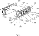
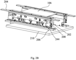
- FIGS. 2A and 2B are perspective views of the board 106 and the pair of adjustment assemblies 108 shown in FIG. 1B from different perspectives.
- FIG. 2C is a front view of the board 106 and the pair of adjustment assemblies 108 shown in FIG. 2A .
- two adjustment assemblies 108 of the pair of adjustment assemblies 108 are symmetrically arranged.
- the adjustment assembly 108 is generally elongated to support the board 106 over a length.
- the pair of adjustment assemblies 108 can move along a first direction (i.e., a vertical direction) and are formed by extending along a second direction (i.e., front and rear directions) that is substantially perpendicular to the first direction.
- the two adjustment assemblies 108 of the pair of adjustment assemblies 108 are mirror-image arranged about a vertical plane formed by the first direction and the second direction.
- the board 106 is generally a flat board and is arranged substantially along a horizontal plane formed by the second direction and a third direction (i.e., left and right directions).
- the board 106 is located substantially between the pair of adjustment assemblies 108, and opposite edges of the board 106 are supported by the pair of adjustment assemblies 108.
- the board 106 has a first edge portion (i.e., a left edge portion) 221 and a second edge portion (i.e., a right edge portion) 222 arranged oppositely in the third direction.
- each adjustment assembly 108 of the pair of adjustment assemblies 108 includes a carrying component 202, an alignment component 204, a drive component 210, an alignment component support assembly 216 and a transmission assembly.
- the carrying component 202 is used to carry the board 106.
- the alignment component 204 is used to be aligned (i.e., flush) with the board 106, so as to set the position of the board 106.
- the alignment component support assembly 216 is configured to support the alignment component 204.
- the drive component 210 is configured to drive the carrying component 202 and the alignment component 204 to move and can adjust a distance between an upper surface of the carrying component 202 and an upper surface of the alignment component 204 to be equal to the thickness of the board.
- the transmission assembly is configured to enable the drive component 210 to drive the carrying component 202 and the alignment component 204 to move.
- the transmission assembly includes a guide rod 206 and a clamp 208.
- the drive component 210 can drive the guide rod 206 to move.
- the clamp 208 is arranged on the alignment component 204 and is configured to be capable of clamping or releasing the guide rod 206.
- the transmission assembly is configured such that: when the clamp 208 releases the guide rod 206, the drive component 210 can drive the guide rod 206 to move relative to the carrying component 202 and the alignment component 204; and when the clamp 208 clamps the guide rod 206, the drive component 210 can drive the guide rod 206 and the alignment component 204 to move relative to the carrying component 202.
- the carrying component 202, the guide rod 206 and the drive component 210 are configured such that: when the drive component 210 drives the carrying component 202 to move, the drive component 210 drives the guide rod 206 to move.
- FIG. 2D is an exploded view of a right-hand adjustment assembly 108.
- the structures and mating relationship of the components of the right-hand adjustment assembly 108 will be described with reference to FIG. 2A , in conjunction with the right half of FIG. 2C .
- Those skilled in the art can symmetrically arrange a left-hand adjustment assembly 108 according to the structures and mating relationship of the components of the right-hand adjustment assembly 108.
- the carrying component 202 is formed by extending substantially along the second direction.
- the carrying component 202 includes a vertical plate 212 and a transverse plate 214.
- the vertical plate 212 extends a distance substantially along the first direction and the transverse plate 214 extends a distance substantially along the third direction.
- a lower end portion of the vertical plate 212 is connected to a left end portion of the transverse plate 214 so that a cross-section of the carrying component is substantially L-shaped.
- An upper end portion of the vertical plate 212 has an upper surface 232.
- the upper surface 232 is a planar surface for supporting the board 106.
- the transverse plate 214 is provided with a through hole 242.
- the through hole 242 extends through the transverse plate 214 along the first direction, for receiving the guide rod 206.
- the transverse plate 214 has a lower surface 246 for abutment with the drive component 210, such that the drive component 210 can drive the transverse plate 214 to move.
- the alignment component 204 is a plate, which is arranged substantially along the horizontal plane formed by the second direction and the third direction.
- the alignment component 204 has an upper surface 234.
- the alignment component support assembly 216 is arranged below the alignment component 204 and is connected to the alignment component 204 for supporting the alignment component 204, to prevent deformation of the alignment component 204 in the second direction.
- the clamp 208 is arranged below the alignment component 204 and is connected to the alignment component 204.
- the clamp 208 can clamp or release the guide rod 206.
- the clamp 208 is a jaw having a lower opening.
- the guide rod 206 can be accommodated in the lower opening.
- the clamp 208 and the guide rod 206 do not move relative to each other.
- the clamp 208 is a gas cylinder.
- a piston of the gas cylinder moves along the horizontal plane toward the guide rod 206 and abuts against the guide rod 206 to clamp the guide rod 206.
- the piston of the gas cylinder moves away from the guide rod 206 and is separated from the guide rod 206 to release the guide rod 206.
- the guide rod 206 is a rod formed by extending along the first direction. A lower end of the guide rod 206 can pass through the through hole 242 in the carrying component 202.
- the guide rod 206 is provided with a blocking portion 244 to block the guide rod 206 from passing completely through the carrying component 202 through the through hole 242.
- the blocking portion 244 is arranged around the guide rod 206. In other words, the blocking portion 244 is formed by extending outwardly from an outer circumferential surface of the guide rod 206 along a radial direction of the guide rod 206.
- the lower end of the guide rod 206 passes through the through hole 242 located in the transverse plate 214, it is possible to keep a portion of the guide rod 206 (i.e., a lower end portion of the guide rod 206) below the carrying component 202, and a portion of the guide rod 206 (e.g., upper and middle portions of the guide rod 206) above the carrying component 202, because the outer diameter of the blocking portion 244 is larger than the diameter of the through hole 242.
- the drive component 210 is a plate, which is arranged substantially along the horizontal plane formed by the second direction and the third direction.
- the drive component 210 has an upper surface 248 for abutment with the lower surface 246 of the carrying component 202 and the lower end portion of the guide rod 206.
- the drive component 210 can move along the first direction, and thus can drive the carrying component 202, the alignment component 204, the guide rod 206 and the clamp 208 to move along the first direction.
- the drive component 210 of the right-hand adjustment assembly 108 and the drive component 210 of the left-hand adjustment assembly 108 are the same drive plate, so that the same drive source (e.g., motor) can drive the pair of adjustment assemblies 108 simultaneously. It can be understood by those skilled in the art that in other embodiments, the drive component 210 of the right-hand adjustment assembly 108 and the drive component 210 of the left-hand adjustment assembly 108 may be independent.
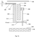
- FIGS. 3A-3E are schematic diagrams showing states of the printing system during operation. The mating relationship and positional relationship between the various components will be described below with reference to FIG. 3A , and the mating relationship between the various components will be described in conjunction with FIGS. 3A-3E , thereby enabling operation of the printing system. It should be noted that a front view of the drive component 210 of the right-hand adjustment assembly 108 is only shown in FIGS. 3A-3E for ease of description. It should also be noted that a wire screen 106 remains stationary during the operation of the printing system.
- the components of the printing system are located in their initial positions before the printing system prints on the board 106.
- the carrying component 202, the alignment component 204, and the transmission assembly are located between the wire screen 106 and the drive component 210.
- the alignment component 204 is located on a right side of the vertical plate 212 of the carrying component 202 in the third direction, and above the transverse plate 214 of the carrying component 202 in the first direction.
- the guide rod 206 passes through the through hole 242 in the carrying component 202.
- the clamp 208 releases the guide rod 206.
- the upper surface 232 of the carrying component 202 is at the same height as the upper surface 234 of the alignment component 204.
- the drive component 210 is separated from the carrying component 202 and the guide rod 206.
- the height of the lower surface 246 of the carrying component 202 is referred to as "0 level" when the components of the printing system are in the initial positions.
- a worker may place a board 106 of a thickness h on the upper surface 232 of the carrying component 202.
- the worker may then operate the drive component 210 to move upwardly along the first direction toward the wire screen 106. As shown in FIGS. 3A-3B , the drive component 210 will move upwardly until the upper surface 248 of the drive component 210 abuts against the lower end of the guide rod 206.
- the upward movement of the drive component 210 toward the wire screen 106 in the first direction will drive the guide rod 206 to move upwardly toward the wire screen 106 in the first direction, until the height difference between the upper surface 248 of the drive component 210 and the lower surface 246 of the carrying component 202 is equal to the thickness h of the board 106.
- the upper surface 248 of the drive component 210 is located at a distance h below the O level in this case.
- the clamp 208 arranged on the alignment component 204 clamps the guide rod 206.
- the alignment component 204 can be driven to move along the first direction.
- the drive component 210 continues to move upwardly along the first direction toward the wire screen 106.
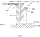
- the drive component 210 drives the alignment component 204 to move upwardly along the first direction until the upper surface 248 of the drive component 210 abuts against the lower surface 246 of the carrying component 202.
- the upper surface 248 of the drive component 210 is at the O level, and the height difference between the upper surface 234 of the alignment component 204 and the upper surface 232 of the carrying component 202 in the first direction is equal to the thickness h of the board 106.
- the upper surface 234 of the alignment component 204 is at the same height as (i.e., flush with) the upper surface of the board 106.
- the drive component 210 continues to move upwardly along the first direction toward the wire screen 106.
- the drive component 210 drives the carrying component 202, the alignment component 204, the transmission assembly and the board 106 to move upwardly together along the first direction toward the wire screen 106 until the upper surface 234 of the alignment component 204 and the upper surface of the board 106 are together attached to (i.e., abut against) the lower surface of the wire screen 106.
- the print head (not shown) of the printing device (not shown) lon the wire screen 106 abuts against the upper surface of the wire screen 104 and moves relative to the wire screen 104, such that the predetermined pattern is printed on the upper surface of the board 106.
- the structure of the printing system of the present disclosure enables a height difference between the upper surface of the alignment component and the upper surface of the carrying component to be adjusted according to the thickness of the board to be processed, such that the height difference between the upper surface of the alignment component and the upper surface of the carrying component is equal to the thickness of the board to be processed, so as to accommodate boards of different thicknesses to be processed.
- FIG. 4 is a schematic diagram of control process of the printing system of the present disclosure.
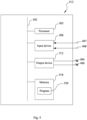
- the printing system further includes a control device 412, an actuation device 401, a first sensor 414 and a second sensor 416.
- the actuation device 401 is configured to drive the drive component 210 to move along the first direction.
- the actuation device 401 is a motor.
- the actuation device 401 is communicatively connected to the control device 412 via a signal 404.
- the control device 412 is configured to control activation and deactivation of the actuation device 401, so as to control whether the drive component 210 moves along the first direction.
- the clamp 208 is communicatively connected to the control device 412 via a signal 406.
- the control device 412 is configured to control the clamp 208 to clamp or release the guide rod 206.
- the first sensor 414 is configured to detect whether the height difference between the upper surface 248 of the drive component 210 and the lower surface 246 of the carrying component 202 is equal to the thickness h of the board 106.
- the first sensor 414 is communicatively connected to the control device 412 via a signal 407.
- the first sensor 414 When the first sensor 414 detects that the height difference between the upper surface 248 of the drive component 210 and the lower surface 246 of the carrying component 202 is equal to the thickness h of the board 106, the first sensor 414 sends a first signal to the control device 412.
- the control device 412 controls the clamp 208 to clamp the guide rod 206 in accordance with the first signal.
- the second sensor 416 is configured to detect whether the upper surface of the alignment component 204 is attached to the lower surface of the wire screen 106.
- the second sensor 416 is communicatively connected to the control device 412 via a signal 408.
- the second sensor 416 When the second sensor 416 detects that the upper surface 234 of the alignment component 204 is attached to the lower surface of the wire screen 106, the second sensor 416 sends a second signal to the control device 412.
- the control device 412 controls the actuation device 401 in accordance with the second signal to deactivate, such that the alignment component 204 and the upper surface of the board 106 at the same height as the upper surface 234 of the alignment component 204 are maintained in place.
- FIG. 5 is a schematic diagram of the internal structure of the control device 412 shown in FIG. 4 .
- the control device 412 includes a bus 502, a processor 505, an input device 508, an output device 512, and a memory 518 having a control program 520.
- the components in the control device 412, including the processor 505, the input device 508, the output device 512 and the memory 518, are communicatively connected to the bus 502, such that the processor 505 can control operations of the input device 508, the output device 512 and the memory 518.
- the memory 518 is configured to store programs, instructions and data
- the processor 505 reads the programs, instructions and data from the memory 518 and can write data to the memory 518.
- the processor 505 controls the operations of the input device 508 and the output device 512 by means of executing the programs and the instructions read from the memory 518.
- the input device 508 receives, via connections 407 and 408, foreign signals and data, including the height difference between the upper surface 248 of the drive component 210 and the lower surface 246 of the carrying component 202 being equal to the thickness h of the board 106 detected from the first sensor 414, and the upper surface 234 of the alignment component 204 being attached to the lower surface of the wire screen 106 detected from the second sensor 416.
- the output device 512 sends control signals via the connections 404 and 406 to the actuation device 401 and the clamp 208, respectively, to control the activation and deactivation of the actuation device 401 and control the clamping or release of the clamp 208.
- a program for implementing the flow chart shown in FIGS. 6-7 is stored in the memory 518 of the control device 412.
- the processor 505 executes the program stored in the control device 412, such that the control device 412 controls the actuation device 401 and the clamp 208.
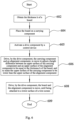
- FIG. 6 is a control flow chart about how does the control device 412 control the printing system.
- the processor 505 obtains the thickness h of a board 106 to be processed.
- a worker may measure the thickness h of the board 106 and then input it into the memory 518.
- the printing system may include a measuring device.
- the measuring device is communicatively connected to the control device 412.
- the measuring device is configured to measure the thickness h of the board 106 to be processed, and the measured data is then sent to the control device 412.
- the processor 505 proceeds the operation to step 604.
- step 604 the board 106 is placed on the carrying component 202.
- the board 106 may be placed on the carrying component 202 by the worker.
- the printing system may include a gripping device.
- the gripping device is communicatively connected to the control device 412.
- the gripping device is configured to grip the board 106 to be processed and place the board 106 on the carrying component 202.
- the processor 505 proceeds the operation to step 605.
- step 605 the control device 412 activates the drive component 210.
- the processor 505 proceeds the operation to step 606.
- step 606 the control device 412 controls the drive component 210 to drive the carrying component 202 and an alignment component 204, to adjust a height difference between an upper surface of the carrying component 202 and an upper surface of the alignment component 204 to be equal to the thickness h of the board, and to make the upper surface of the carrying component 202 to be lower than the upper surface of the alignment component 204.
- the processor 505 proceeds the operation to step 608.
- step 608 the control device 412 controls the drive component 210 to drive the board 106 and the alignment component 204 to move, until an upper surface of the board 106 and the upper surface of the alignment component 204 attach to the lower surface of a wire screen 106.
- FIG. 7 is a detailed control flow chart of step 606 shown in FIG. 6 .
- the control device 412 allows the upper surface of the carrying component 202 to be at the same height as the upper surface of the alignment component 204.
- the processor 505 proceeds the operation to step 704.
- step 704 the control device 412 controls the drive component 210 to drive the guide rod 206 to move upwardly.
- the processor 505 proceeds the operation to step 706.
- step 706 the control device 412 determines whether a first signal is received. In other words, the control device 412 determines whether a distance between tan upper surface of the drive component 210 and a lower surface of the carrying component 202 is equal to the thickness of the board 106. If the control device 412 does not receive the first signal, the processor 505 proceeds the operation to step 704. If the control device 412 receives the first signal, the processor 505 proceeds the operation to step 708.
- step 708 the control device 412 controls the clamp 208 to clamp the guide rod 206.
- the processor 505 proceeds the operation to step 710.
- step 710 the control device 412 controls the the drive component 210 to move upwardly, so as to drive the guide rod 206, the clamp 208 and the alignment component 204 to move upwardly, until the upper surface of the drive component 210 abuts against the lower surface of the carrying component 202.
- the height difference between the upper surface of the carrying component 202 and the upper surface of the alignment component is equal to the thickness of the board 106.
- the processor 505 proceeds the operation back to step 608.
- FIG. 8 is a detailed control flow chart of step 608 shown in FIG. 6 .
- the drive component 210 drives the alignment component 204, the board 106 and the carrying component 202 to move upwardly.
- the processor 505 proceeds the operation to step 804.
- step 804 the control device 412 determines whether a second signal is received. In other words, the control device 412 determines whether the upper surface of the board 106 and the upper surface of the alignment component 204 are attached a lower surface of the wire screen 104. If the control device 412 does not receive the second signal, the processor 505 proceeds the operation to step 802. If the control device 412 receives the second signal, the processor 505 proceeds the operation to step 804.
- step 804 the control device 412 deactivates the drive component 210.
- the processor 505 proceeds the operation back to step 609.
Landscapes
- Engineering & Computer Science (AREA)
- Mechanical Engineering (AREA)
- Manufacturing & Machinery (AREA)
- Microelectronics & Electronic Packaging (AREA)
- Screen Printers (AREA)
- Printing Methods (AREA)
- Manufacturing Of Printed Wiring (AREA)
- Handling Of Sheets (AREA)
- Registering Or Overturning Sheets (AREA)
Abstract
The present disclosure provides a printing system and a method for controlling a printing system. The printing system is used to print on a board, and includes at least one pair of adjustment assemblies. Each of the at least one pair of adjustment assemblies includes a carrying component, an alignment component and a drive component. The carrying component is configured to carry the board. The drive component is configured to be capable of driving the carrying component and the alignment component to move and is configured to adjust a distance between an upper surface of the carrying component and an upper surface of the alignment component to be equal to the thickness of the board. The structure of the printing system of the present disclosure enables a height difference between the upper surface of the alignment component and the upper surface of the carrying component to be adjusted according to the thickness of the board to be processed, such that the height difference between the upper surface of the alignment component and the upper surface of the carrying component is equal to the thickness of the board to be processed, so as to adapt to boards of different thicknesses to be processed.
Description
- The present disclosure relates to a printing system.
- A printing system includes a printing device and a wire screen. upper surface of a board (e.g., PCB) to be processed is attached to or abuts against a lower surface of the wire screen, such that the printing device can print a pattern of the wire screen on the board to be processed. There is therefore a need for a printing system that enables the upper surface of the board (e.g., PCB) to be processed to abut against the lower surface of the wire screen.
- The present disclosure provides a printing system for printing a board, the printing system including at least one pair of adjustment assemblies. Each of the at least one pair of adjustment assemblies includes a carrying component, an alignment component and a drive component. The carrying component is configured to carry the board. The drive component is configured to be capable of driving the carrying component and the alignment component to move and is configured to adjust a distance between an upper surface of the carrying component and an upper surface of the alignment component to be equal to the thickness of the board.
- According to the printing system described above, each of the at least one pair of adjustment assemblies further includes a transmission assembly. The transmission assembly includes a guide rod and a clamp. The drive component is capable of driving the guide rod to move. The clamp is arranged on the alignment component and is configured to be capable of clamping or releasing the guide rod.
- According to the printing system described above, the transmission assembly is configured such that:
- when the clamp releases the guide rod, the drive component is capable of driving the guide rod to move relative to the carrying component and the alignment component; and
- when the clamp clamps the guide rod, the drive component is capable of driving the guide rod and the alignment component to move relative to the carrying component.
- According to the printing system described above, the carrying component, the guide rod and the drive component are configured such that: when the drive component drives the carrying component to move, the drive component drives the guide rod to move.
- According to the printing system described above, the carrying component is provided with a through hole, and the guide rod is capable of passing through the through hole.
- According to the printing system described above, the drive component is configured to be capable of driving the carrying component, the alignment component, the guide rod and the clamp to move along a first direction.
- According to the printing system described above, the drive components of the at least one pair of adjustment assemblies are the same drive plate.
- According to the printing system described above, the printing system further includes a wire screen, wherein the wire screen and the drive component are arranged on opposite sides of the carrying component and the alignment component. The drive component is configured to be capable of driving the board carried by the carrying component and the alignment component to be attached to a lower surface of the wire screen.
- The present disclosure also provides a method for controlling a printing system, the method including:
- obtaining the thickness of a board;
- driving a carrying component and an alignment component by means of a drive component to move so as to adjust a height difference between an upper surface of the carrying component and an upper surface of the alignment component to be equal to the thickness of the board and making the upper surface of the carrying component to be lower than the upper surface of the alignment component.
- The method for controlling a printing system described above further includes: driving the carrying component, the board and the alignment component by means of the drive component to move until the upper surface of the alignment component is attached to a lower surface of a wire screen, after the step of driving a carrying component and an alignment component by means of a drive component to move so as to adjust a height difference between an upper surface of the carrying component and an upper surface of the alignment component to be equal to the thickness of the board and making the upper surface of the carrying component to be lower than the upper surface of the alignment component.
- According to the method for controlling a printing system described above, the step of driving a carrying component and an alignment component by means of a drive component to move so as to adjust a height difference between an upper surface of the carrying component and an upper surface of the alignment component to be equal to the thickness of the board and making the upper surface of the carrying component to be lower than the upper surface of the alignment component includes:
- allowing the upper surface of the carrying component to be at the same height as the upper surface of the alignment component;
- driving a guide rod by means of the drive component to move until a distance between an upper surface of the drive component and a lower surface of the carrying component is equal to the thickness of the board;
- clamping the guide rod by means of a clamp arranged on the alignment component;
- driving the guide rod and the alignment component by means of the drive component to move until the height difference between the upper surface of the carrying component and the upper surface of the alignment component is equal to the thickness of the board.
- The structure of the printing system of the present disclosure enables a height difference between the upper surface of the alignment component and the upper surface of the carrying component to be adjusted according to the thickness of the board to be processed, such that the height difference between the upper surface of the alignment component and the upper surface of the carrying component is equal to the thickness of the board to be processed, so as to adapt to boards of different thicknesses to be processed.
- Other features, advantages and embodiments of the present disclosure may be elaborated or become apparent by considering the following specific embodiments, accompanying drawings and claims. Furthermore, it should be appreciated that the summary and the following specific embodiments are all exemplary, and are intended to provide a further explanation, but not to limit the scope of protection of the present disclosure. However, the specific embodiments and specific examples merely indicate preferred embodiments of the present disclosure. For those skilled in the art, various variations and modifications within the spirit and scope of the present disclosure will become apparent by the way of the specific embodiments.
- The features and advantages of the present disclosure may be better understood by reading the following detailed description with reference to the accompanying drawings. In all the accompanying drawings, the same reference numerals represent the same parts, in the figures:
-
FIG. 1A is a perspective view of a printing system according to the present disclosure; -
FIG. 1B is a perspective view of the printing system shown inFIG. 1A ; -
FIGS. 2A and2B are perspective views of a board and a pair of adjustment assemblies shown inFIG. 1B from different perspectives; -
FIG. 2C is a front view of the board and the pair of adjustment assemblies shown inFIG. 2A ; -
FIG. 2D is an exploded view of a right-hand adjustment assembly; -
FIGS. 3A-3E are schematic diagrams showing various states of the printing system during operation; -
FIG. 4 is a schematic diagram of control process of the printing system of the present disclosure; -
FIG. 5 is a schematic diagram of the internal structure of a control device shown inFIG. 4 ; -
FIG. 6 is a control flow chart about how does a control device control the printing system; -
FIG. 7 is a detailed control flow chart ofstep 606 shown inFIG. 6 ; and -
FIG. 8 is a detailed control flow chart ofstep 608 shown inFIG. 6 . - Various specific embodiments of the present disclosure are described below with reference to the drawings which constitute part of this description.
-
FIG. 1A is a perspective view of a printing system according to the present disclosure. As shown inFIG. 1A , the printing system is used to print aboard 106 to be processed (seeFIG. 1B ). Specifically, the printing system includes abase 102, awire screen 104, a printing device (not shown), and a wirescreen support device 110. The wirescreen support device 110 is arranged on thebase 102. The wirescreen support device 110 is used to support thewire screen 104 and to arrange thewire screen 104 at a distance from thebase 102. The printing device configured to be capable of printing, is arranged above thewire screen 104, and can move relative to thewire screen 104. Thewire screen 104 is provided with perforations. The perforations form a predetermined pattern. When it is necessary to print theboard 106 to be processed, an upper surface of theboard 106 to be processed first abuts against a lower surface of thewire screen 104, and a print head (not shown) of the printing device abuts against an upper surface of thewire screen 104 and moves relative to thewire screen 104, such that the predetermined pattern is printed on the upper surface of theboard 106. -
FIG. 1B is a perspective view of the printing system shown inFIG. 1A , with thewire screen 104 not shown inFIG. 1B . As shown inFIG. 1B , the printing system further includes a pair ofadjustment assemblies 108. Theadjustment assembly 108 is arranged below thewire screen 104 and is configured to carry theboard 106. Theadjustment assembly 108 can move relative to thewire screen 104 to transport theboard 106, such that the upper surface of theboard 106 abuts against the lower surface of thewire screen 104. -
FIGS. 2A and2B are perspective views of theboard 106 and the pair ofadjustment assemblies 108 shown inFIG. 1B from different perspectives.FIG. 2C is a front view of theboard 106 and the pair ofadjustment assemblies 108 shown inFIG. 2A . As shown inFIGS. 2A-2C , twoadjustment assemblies 108 of the pair ofadjustment assemblies 108 are symmetrically arranged. Theadjustment assembly 108 is generally elongated to support theboard 106 over a length. In particular, the pair ofadjustment assemblies 108 can move along a first direction (i.e., a vertical direction) and are formed by extending along a second direction (i.e., front and rear directions) that is substantially perpendicular to the first direction. In other words, the twoadjustment assemblies 108 of the pair ofadjustment assemblies 108 are mirror-image arranged about a vertical plane formed by the first direction and the second direction. Theboard 106 is generally a flat board and is arranged substantially along a horizontal plane formed by the second direction and a third direction (i.e., left and right directions). Theboard 106 is located substantially between the pair ofadjustment assemblies 108, and opposite edges of theboard 106 are supported by the pair ofadjustment assemblies 108. In other words, theboard 106 has a first edge portion (i.e., a left edge portion) 221 and a second edge portion (i.e., a right edge portion) 222 arranged oppositely in the third direction. - As shown in
FIGS. 2A-2C , eachadjustment assembly 108 of the pair ofadjustment assemblies 108 includes a carryingcomponent 202, analignment component 204, adrive component 210, an alignmentcomponent support assembly 216 and a transmission assembly. The carryingcomponent 202 is used to carry theboard 106. Thealignment component 204 is used to be aligned (i.e., flush) with theboard 106, so as to set the position of theboard 106. The alignmentcomponent support assembly 216 is configured to support thealignment component 204. Thedrive component 210 is configured to drive the carryingcomponent 202 and thealignment component 204 to move and can adjust a distance between an upper surface of the carryingcomponent 202 and an upper surface of thealignment component 204 to be equal to the thickness of the board. The transmission assembly is configured to enable thedrive component 210 to drive the carryingcomponent 202 and thealignment component 204 to move. The transmission assembly includes aguide rod 206 and aclamp 208. Thedrive component 210 can drive theguide rod 206 to move. Theclamp 208 is arranged on thealignment component 204 and is configured to be capable of clamping or releasing theguide rod 206. The transmission assembly is configured such that: when theclamp 208 releases theguide rod 206, thedrive component 210 can drive theguide rod 206 to move relative to the carryingcomponent 202 and thealignment component 204; and when theclamp 208 clamps theguide rod 206, thedrive component 210 can drive theguide rod 206 and thealignment component 204 to move relative to the carryingcomponent 202. The carryingcomponent 202, theguide rod 206 and thedrive component 210 are configured such that: when thedrive component 210 drives the carryingcomponent 202 to move, thedrive component 210 drives theguide rod 206 to move. -
FIG. 2D is an exploded view of a right-hand adjustment assembly 108. For simplicity of description, the structures and mating relationship of the components of the right-hand adjustment assembly 108 will be described with reference toFIG. 2A , in conjunction with the right half ofFIG. 2C . Those skilled in the art can symmetrically arrange a left-hand adjustment assembly 108 according to the structures and mating relationship of the components of the right-hand adjustment assembly 108. - As shown in
FIGS. 2A ,2C and2D , the carryingcomponent 202 is formed by extending substantially along the second direction. The carryingcomponent 202 includes avertical plate 212 and atransverse plate 214. Thevertical plate 212 extends a distance substantially along the first direction and thetransverse plate 214 extends a distance substantially along the third direction. A lower end portion of thevertical plate 212 is connected to a left end portion of thetransverse plate 214 so that a cross-section of the carrying component is substantially L-shaped. An upper end portion of thevertical plate 212 has anupper surface 232. Theupper surface 232 is a planar surface for supporting theboard 106. Thetransverse plate 214 is provided with a throughhole 242. The throughhole 242 extends through thetransverse plate 214 along the first direction, for receiving theguide rod 206. Thetransverse plate 214 has alower surface 246 for abutment with thedrive component 210, such that thedrive component 210 can drive thetransverse plate 214 to move. - As shown in
FIGS. 2A ,2C and2D , thealignment component 204 is a plate, which is arranged substantially along the horizontal plane formed by the second direction and the third direction. Thealignment component 204 has anupper surface 234. The alignmentcomponent support assembly 216 is arranged below thealignment component 204 and is connected to thealignment component 204 for supporting thealignment component 204, to prevent deformation of thealignment component 204 in the second direction. - As shown in
FIGS. 2A ,2C and2D , theclamp 208 is arranged below thealignment component 204 and is connected to thealignment component 204. Theclamp 208 can clamp or release theguide rod 206. As an embodiment, theclamp 208 is a jaw having a lower opening. Theguide rod 206 can be accommodated in the lower opening. When the jaw clamps theguide rod 206, theclamp 208 and theguide rod 206 do not move relative to each other. When the jaw does not clamp (i.e., releases) theguide rod 206, theclamp 208 and theguide rod 206 move relative to each other. In an embodiment of the present disclosure, theclamp 208 is a gas cylinder. As a gas enters the gas cylinder, a piston of the gas cylinder moves along the horizontal plane toward theguide rod 206 and abuts against theguide rod 206 to clamp theguide rod 206. As the gas is discharged from the gas cylinder, the piston of the gas cylinder moves away from theguide rod 206 and is separated from theguide rod 206 to release theguide rod 206. - It can be understood by those skilled in the art that in other embodiments, the
clamp 208 may be of any form and structure, a power source of which may be one or more of gas, liquid, electric power, etc., as long as theclamp 208 can clamp or release theguide rod 206. - As shown in
FIGS. 2A ,2C and2D , theguide rod 206 is a rod formed by extending along the first direction. A lower end of theguide rod 206 can pass through the throughhole 242 in the carryingcomponent 202. Theguide rod 206 is provided with a blockingportion 244 to block theguide rod 206 from passing completely through the carryingcomponent 202 through the throughhole 242. Specifically, the blockingportion 244 is arranged around theguide rod 206. In other words, the blockingportion 244 is formed by extending outwardly from an outer circumferential surface of theguide rod 206 along a radial direction of theguide rod 206. When the lower end of theguide rod 206 passes through the throughhole 242 located in thetransverse plate 214, it is possible to keep a portion of the guide rod 206 (i.e., a lower end portion of the guide rod 206) below the carryingcomponent 202, and a portion of the guide rod 206 (e.g., upper and middle portions of the guide rod 206) above the carryingcomponent 202, because the outer diameter of the blockingportion 244 is larger than the diameter of the throughhole 242. - As shown in
FIGS. 2A ,2C and2D , thedrive component 210 is a plate, which is arranged substantially along the horizontal plane formed by the second direction and the third direction. Thedrive component 210 has anupper surface 248 for abutment with thelower surface 246 of the carryingcomponent 202 and the lower end portion of theguide rod 206. Thedrive component 210 can move along the first direction, and thus can drive the carryingcomponent 202, thealignment component 204, theguide rod 206 and theclamp 208 to move along the first direction. - In an embodiment of the present disclosure, the
drive component 210 of the right-hand adjustment assembly 108 and thedrive component 210 of the left-hand adjustment assembly 108 are the same drive plate, so that the same drive source (e.g., motor) can drive the pair ofadjustment assemblies 108 simultaneously. It can be understood by those skilled in the art that in other embodiments, thedrive component 210 of the right-hand adjustment assembly 108 and thedrive component 210 of the left-hand adjustment assembly 108 may be independent. -
FIGS. 3A-3E are schematic diagrams showing states of the printing system during operation. The mating relationship and positional relationship between the various components will be described below with reference toFIG. 3A , and the mating relationship between the various components will be described in conjunction withFIGS. 3A-3E , thereby enabling operation of the printing system. It should be noted that a front view of thedrive component 210 of the right-hand adjustment assembly 108 is only shown inFIGS. 3A-3E for ease of description. It should also be noted that awire screen 106 remains stationary during the operation of the printing system. - As shown in
FIG. 3A , the components of the printing system are located in their initial positions before the printing system prints on theboard 106. Specifically, the carryingcomponent 202, thealignment component 204, and the transmission assembly are located between thewire screen 106 and thedrive component 210. Thealignment component 204 is located on a right side of thevertical plate 212 of the carryingcomponent 202 in the third direction, and above thetransverse plate 214 of the carryingcomponent 202 in the first direction. Theguide rod 206 passes through the throughhole 242 in the carryingcomponent 202. Theclamp 208 releases theguide rod 206. Theupper surface 232 of the carryingcomponent 202 is at the same height as theupper surface 234 of thealignment component 204. Thedrive component 210 is separated from the carryingcomponent 202 and theguide rod 206. The height of thelower surface 246 of the carryingcomponent 202 is referred to as "0 level" when the components of the printing system are in the initial positions. - When the components of the printing system are in the initial positions, a worker may place a
board 106 of a thickness h on theupper surface 232 of the carryingcomponent 202. - The worker may then operate the
drive component 210 to move upwardly along the first direction toward thewire screen 106. As shown inFIGS. 3A-3B , thedrive component 210 will move upwardly until theupper surface 248 of thedrive component 210 abuts against the lower end of theguide rod 206. - It should be noted that during the operation as shown in
FIGS. 3A-3B , the carryingcomponent 202, thealignment component 204 and theguide rod 206 are all maintained in their respective initial positions. Theboard 106 does not move relative to the wire screen. - As shown in
FIGS. 3B-3C , after thedrive component 210 abuts against the lower end of theguide rod 206, the upward movement of thedrive component 210 toward thewire screen 106 in the first direction will drive theguide rod 206 to move upwardly toward thewire screen 106 in the first direction, until the height difference between theupper surface 248 of thedrive component 210 and thelower surface 246 of the carryingcomponent 202 is equal to the thickness h of theboard 106. In other words, theupper surface 248 of thedrive component 210 is located at a distance h below the O level in this case. - It should be noted that during the operation as shown in
FIGS. 3B-3C , the carryingcomponent 202 and thealignment component 204 are both maintained in their respective initial positions. Theboard 106 does not move relative to the wire screen. - As shown in
FIG. 3C , when theupper surface 248 of thedrive component 210 is located at a distance h below the O level, theclamp 208 arranged on thealignment component 204 clamps theguide rod 206. In this way, when thedrive component 210 drives theguide rod 206 to move along the first direction, thealignment component 204 can be driven to move along the first direction. - As shown in
FIGS. 3C-3D , thedrive component 210 continues to move upwardly along the first direction toward thewire screen 106. Thedrive component 210 drives thealignment component 204 to move upwardly along the first direction until theupper surface 248 of thedrive component 210 abuts against thelower surface 246 of the carryingcomponent 202. In this case, theupper surface 248 of thedrive component 210 is at the O level, and the height difference between theupper surface 234 of thealignment component 204 and theupper surface 232 of the carryingcomponent 202 in the first direction is equal to the thickness h of theboard 106. In other words, theupper surface 234 of thealignment component 204 is at the same height as (i.e., flush with) the upper surface of theboard 106. - It should be noted that during the operation as shown in
FIGS. 3C-3D , the carryingcomponent 202 is maintained in its initial position. Theboard 106 does not move relative to the wire screen. - As shown in
FIGS. 3D-3E , thedrive component 210 continues to move upwardly along the first direction toward thewire screen 106. Thedrive component 210 drives the carryingcomponent 202, thealignment component 204, the transmission assembly and theboard 106 to move upwardly together along the first direction toward thewire screen 106 until theupper surface 234 of thealignment component 204 and the upper surface of theboard 106 are together attached to (i.e., abut against) the lower surface of thewire screen 106. The print head (not shown) of the printing device (not shown) lon thewire screen 106 abuts against the upper surface of thewire screen 104 and moves relative to thewire screen 104, such that the predetermined pattern is printed on the upper surface of theboard 106. - The structure of the printing system of the present disclosure enables a height difference between the upper surface of the alignment component and the upper surface of the carrying component to be adjusted according to the thickness of the board to be processed, such that the height difference between the upper surface of the alignment component and the upper surface of the carrying component is equal to the thickness of the board to be processed, so as to accommodate boards of different thicknesses to be processed.
-
FIG. 4 is a schematic diagram of control process of the printing system of the present disclosure. As shown inFIG. 4 , the printing system further includes acontrol device 412, anactuation device 401, afirst sensor 414 and asecond sensor 416. Theactuation device 401 is configured to drive thedrive component 210 to move along the first direction. As an example, theactuation device 401 is a motor. Theactuation device 401 is communicatively connected to thecontrol device 412 via asignal 404. Thecontrol device 412 is configured to control activation and deactivation of theactuation device 401, so as to control whether thedrive component 210 moves along the first direction. When thecontrol device 412 control theactuation device 401 to deactivate, theactuation device 401 enables thedrive component 210 to keep at a position in the first direction. Theclamp 208 is communicatively connected to thecontrol device 412 via asignal 406. Thecontrol device 412 is configured to control theclamp 208 to clamp or release theguide rod 206. Thefirst sensor 414 is configured to detect whether the height difference between theupper surface 248 of thedrive component 210 and thelower surface 246 of the carryingcomponent 202 is equal to the thickness h of theboard 106. Thefirst sensor 414 is communicatively connected to thecontrol device 412 via asignal 407. When thefirst sensor 414 detects that the height difference between theupper surface 248 of thedrive component 210 and thelower surface 246 of the carryingcomponent 202 is equal to the thickness h of theboard 106, thefirst sensor 414 sends a first signal to thecontrol device 412. Thecontrol device 412 controls theclamp 208 to clamp theguide rod 206 in accordance with the first signal. Thesecond sensor 416 is configured to detect whether the upper surface of thealignment component 204 is attached to the lower surface of thewire screen 106. Thesecond sensor 416 is communicatively connected to thecontrol device 412 via asignal 408. When thesecond sensor 416 detects that theupper surface 234 of thealignment component 204 is attached to the lower surface of thewire screen 106, thesecond sensor 416 sends a second signal to thecontrol device 412. Thecontrol device 412 controls theactuation device 401 in accordance with the second signal to deactivate, such that thealignment component 204 and the upper surface of theboard 106 at the same height as theupper surface 234 of thealignment component 204 are maintained in place. -
FIG. 5 is a schematic diagram of the internal structure of thecontrol device 412 shown inFIG. 4 . As shown inFIG. 4 , thecontrol device 412 includes abus 502, aprocessor 505, aninput device 508, anoutput device 512, and amemory 518 having acontrol program 520. The components in thecontrol device 412, including theprocessor 505, theinput device 508, theoutput device 512 and thememory 518, are communicatively connected to thebus 502, such that theprocessor 505 can control operations of theinput device 508, theoutput device 512 and thememory 518. Specifically, thememory 518 is configured to store programs, instructions and data, and theprocessor 505 reads the programs, instructions and data from thememory 518 and can write data to thememory 518. Theprocessor 505 controls the operations of theinput device 508 and theoutput device 512 by means of executing the programs and the instructions read from thememory 518. Theinput device 508 receives, viaconnections upper surface 248 of thedrive component 210 and thelower surface 246 of the carryingcomponent 202 being equal to the thickness h of theboard 106 detected from thefirst sensor 414, and theupper surface 234 of thealignment component 204 being attached to the lower surface of thewire screen 106 detected from thesecond sensor 416. Theoutput device 512 sends control signals via theconnections actuation device 401 and theclamp 208, respectively, to control the activation and deactivation of theactuation device 401 and control the clamping or release of theclamp 208. - In an embodiment of the present disclosure, a program for implementing the flow chart shown in
FIGS. 6-7 is stored in thememory 518 of thecontrol device 412. Theprocessor 505 executes the program stored in thecontrol device 412, such that thecontrol device 412 controls theactuation device 401 and theclamp 208. -
FIG. 6 is a control flow chart about how does thecontrol device 412 control the printing system. As shown inFIG. 6 , instep 602, theprocessor 505 obtains the thickness h of aboard 106 to be processed. As an embodiment, a worker may measure the thickness h of theboard 106 and then input it into thememory 518. As another embodiment, the printing system may include a measuring device. The measuring device is communicatively connected to thecontrol device 412. The measuring device is configured to measure the thickness h of theboard 106 to be processed, and the measured data is then sent to thecontrol device 412. Upon completion ofstep 602, theprocessor 505 proceeds the operation to step 604. - In
step 604, theboard 106 is placed on the carryingcomponent 202. As an embodiment, theboard 106 may be placed on the carryingcomponent 202 by the worker. As another embodiment, the printing system may include a gripping device. The gripping device is communicatively connected to thecontrol device 412. The gripping device is configured to grip theboard 106 to be processed and place theboard 106 on the carryingcomponent 202. Upon completion ofstep 604, theprocessor 505 proceeds the operation to step 605. - In
step 605, thecontrol device 412 activates thedrive component 210. Upon completion ofstep 605, theprocessor 505 proceeds the operation to step 606. - In
step 606, thecontrol device 412 controls thedrive component 210 to drive the carryingcomponent 202 and analignment component 204, to adjust a height difference between an upper surface of the carryingcomponent 202 and an upper surface of thealignment component 204 to be equal to the thickness h of the board, and to make the upper surface of the carryingcomponent 202 to be lower than the upper surface of thealignment component 204. Upon completion ofstep 606, theprocessor 505 proceeds the operation to step 608. - In
step 608, thecontrol device 412 controls thedrive component 210 to drive theboard 106 and thealignment component 204 to move, until an upper surface of theboard 106 and the upper surface of thealignment component 204 attach to the lower surface of awire screen 106. -
FIG. 7 is a detailed control flow chart ofstep 606 shown inFIG. 6 . As shown inFIG. 7 , instep 702, thecontrol device 412 allows the upper surface of the carryingcomponent 202 to be at the same height as the upper surface of thealignment component 204. Upon completion ofstep 702, theprocessor 505 proceeds the operation to step 704. - In
step 704, thecontrol device 412 controls thedrive component 210 to drive theguide rod 206 to move upwardly. Upon completion ofstep 702, theprocessor 505 proceeds the operation to step 706. - In
step 706, thecontrol device 412 determines whether a first signal is received. In other words, thecontrol device 412 determines whether a distance between tan upper surface of thedrive component 210 and a lower surface of the carryingcomponent 202 is equal to the thickness of theboard 106. If thecontrol device 412 does not receive the first signal, theprocessor 505 proceeds the operation to step 704. If thecontrol device 412 receives the first signal, theprocessor 505 proceeds the operation to step 708. - In
step 708, thecontrol device 412 controls theclamp 208 to clamp theguide rod 206. Upon completion ofstep 708, theprocessor 505 proceeds the operation to step 710. - In
step 710, thecontrol device 412 controls the thedrive component 210 to move upwardly, so as to drive theguide rod 206, theclamp 208 and thealignment component 204 to move upwardly, until the upper surface of thedrive component 210 abuts against the lower surface of the carryingcomponent 202. In other words, when the upper surface of thedrive component 210 abuts against the lower surface of the carryingcomponent 202, the height difference between the upper surface of the carryingcomponent 202 and the upper surface of the alignment component is equal to the thickness of theboard 106. Theprocessor 505 proceeds the operation back to step 608. -
FIG. 8 is a detailed control flow chart ofstep 608 shown inFIG. 6 . As shown inFIG. 8 , instep 802, thedrive component 210 drives thealignment component 204, theboard 106 and the carryingcomponent 202 to move upwardly. Upon completion ofstep 802, theprocessor 505 proceeds the operation to step 804. - In
step 804, thecontrol device 412 determines whether a second signal is received. In other words, thecontrol device 412 determines whether the upper surface of theboard 106 and the upper surface of thealignment component 204 are attached a lower surface of thewire screen 104. If thecontrol device 412 does not receive the second signal, theprocessor 505 proceeds the operation to step 802. If thecontrol device 412 receives the second signal, theprocessor 505 proceeds the operation to step 804. - In
step 804, thecontrol device 412 deactivates thedrive component 210. Theprocessor 505 proceeds the operation back to step 609. - Although the present disclosure is described with reference to the examples of embodiments outlined above, various alternatives, modifications, variations, improvements and/or substantial equivalents, which are known or anticipated at present or to be anticipated before long, may be obvious to those of at least ordinary skill in the art. In addition, the technical effects and/or technical problems described in this specification are exemplary rather than limiting; Therefore, the disclosure in this specification may be used to solve other technical problems and have other technical effects and/or may solve other technical problems. Accordingly, the examples of the embodiments of the present disclosure as set forth above are intended to be illustrative rather than limiting. Various changes may be made without departing from the spirit or scope of the present disclosure. Therefore, the present disclosure is intended to embrace all known or earlier disclosed alternatives, modifications, variations, improvements and/or substantial equivalents.
Claims (11)
- A printing system for printing a board, the printing system comprising:
at least one pair of adjustment assemblies, each of which comprises:a carrying component being configured to carry the board;an alignment component; anda drive component being configured to be capable of driving the carrying component and the alignment component to move and being configured to adjust a distance between an upper surface of the carrying component and an upper surface of the alignment component to be equal to the thickness of the board. - The printing system of claim 1, wherein each of the at least one pair of adjustment assemblies further comprises:
a transmission assembly comprising:a guide rod, the drive component being capable of driving the guide rod to move; anda clamp being arranged on the alignment component and being configured to be capable of clamping or releasing the guide rod. - The printing system of claim 2, wherein
the transmission assembly is configured such that:when the clamp releases the guide rod, the drive component is capable of driving the guide rod to move relative to the carrying component and the alignment component; andwhen the clamp clamps the guide rod, the drive component is capable of driving the guide rod and the alignment component to move relative to the carrying component. - The printing system of claim 2, wherein
the carrying component, the guide rod and the drive component are configured such that:
when the drive component drives the carrying component to move, the drive component drives the guide rod to move. - The printing system of claim 4, wherein
the carrying component is provided with a through hole, and the guide rod is capable of passing through the through hole. - The printing system of claim 2, wherein
the drive component is configured to be capable of driving the carrying component, the alignment component, the guide rod and the clamp to move along a first direction. - The printing system of claim 1, wherein
the drive components of the at least one pair of adjustment assemblies are the same drive plate. - The printing system of claim 1, further comprising:a wire screen, wherein the wire screen and the drive component are arranged on opposite sides of the carrying component and the alignment component;wherein the drive component is configured to be capable of driving the board carried by the carrying component and the alignment component to be attached to a lower surface of the wire screen.
- A method for controlling a printing system, comprising:obtaining the thickness of a board;driving a carrying component and an alignment component by means of a drive component to move so as to adjust a height difference between an upper surface of the carrying component and an upper surface of the alignment component to be equal to the thickness of the board and making the upper surface of the carrying component to be lower than the upper surface of the alignment component.
- The method for controlling a printing system according to claim 9, the method further comprising:
driving the carrying component, the board and the alignment component by means of the drive component to move until the upper surface of the alignment component is attached to a lower surface of a wire screen, after the step of driving a carrying component and an alignment component by means of a drive component to move so as to adjust a height difference between an upper surface of the carrying component and an upper surface of the alignment component to be equal to the thickness of the board and making the upper surface of the carrying component to be lower than the upper surface of the alignment component. - The method for controlling a printing system of claim 9, wherein the step of driving a carrying component and an alignment component by means of a drive component to move so as to adjust a height difference between an upper surface of the carrying component and an upper surface of the alignment component to be equal to the thickness of the board and making the upper surface of the carrying component to be lower than the upper surface of the alignment component comprises:allowing the upper surface of the carrying component to be at the same height as the upper surface of the alignment component;driving a guide rod by means of the drive component to move until a distance between an upper surface of the drive component and a lower surface of the carrying components equal to the thickness of the board;clamping the guide rod by means of a clamp arranged on the alignment component;driving the guide rod and the alignment component by means of the drive component to move until the height difference between the upper surface of the carrying component and the upper surface of the alignment component is equal to the thickness of the board.
Applications Claiming Priority (1)
| Application Number | Priority Date | Filing Date | Title |
|---|---|---|---|
| CN202311280466.7A CN119704856A (en) | 2023-09-28 | 2023-09-28 | Printing system and method of controlling printing system |
Publications (1)
| Publication Number | Publication Date |
|---|---|
| EP4530073A1 true EP4530073A1 (en) | 2025-04-02 |
Family
ID=92899962
Family Applications (1)
| Application Number | Title | Priority Date | Filing Date |
|---|---|---|---|
| EP24202342.2A Pending EP4530073A1 (en) | 2023-09-28 | 2024-09-24 | Printing system and method for controlling a printing system |
Country Status (6)
| Country | Link |
|---|---|
| US (1) | US20250108597A1 (en) |
| EP (1) | EP4530073A1 (en) |
| KR (1) | KR20250047617A (en) |
| CN (1) | CN119704856A (en) |
| MX (1) | MX2024011720A (en) |
| TW (1) | TW202527623A (en) |
Citations (3)
| Publication number | Priority date | Publication date | Assignee | Title |
|---|---|---|---|---|
| JP2008114521A (en) * | 2006-11-07 | 2008-05-22 | Matsushita Electric Ind Co Ltd | SCREEN PRINTING APPARATUS AND SUBJECT EXCHANGE METHOD FOR SCREEN PRINTING APPARATUS |
| WO2018070016A1 (en) * | 2016-10-13 | 2018-04-19 | 富士機械製造株式会社 | Screen printer |
| CN108040474A (en) * | 2015-04-07 | 2018-05-15 | 伊利诺斯工具制品有限公司 | Lifting tool component for stenciler |
-
2023
- 2023-09-28 CN CN202311280466.7A patent/CN119704856A/en active Pending
-
2024
- 2024-09-24 EP EP24202342.2A patent/EP4530073A1/en active Pending
- 2024-09-24 MX MX2024011720A patent/MX2024011720A/en unknown
- 2024-09-25 TW TW113136300A patent/TW202527623A/en unknown
- 2024-09-25 US US18/895,706 patent/US20250108597A1/en active Pending
- 2024-09-26 KR KR1020240130596A patent/KR20250047617A/en active Pending
Patent Citations (3)
| Publication number | Priority date | Publication date | Assignee | Title |
|---|---|---|---|---|
| JP2008114521A (en) * | 2006-11-07 | 2008-05-22 | Matsushita Electric Ind Co Ltd | SCREEN PRINTING APPARATUS AND SUBJECT EXCHANGE METHOD FOR SCREEN PRINTING APPARATUS |
| CN108040474A (en) * | 2015-04-07 | 2018-05-15 | 伊利诺斯工具制品有限公司 | Lifting tool component for stenciler |
| WO2018070016A1 (en) * | 2016-10-13 | 2018-04-19 | 富士機械製造株式会社 | Screen printer |
Also Published As
| Publication number | Publication date |
|---|---|
| MX2024011720A (en) | 2025-04-02 |
| TW202527623A (en) | 2025-07-01 |
| US20250108597A1 (en) | 2025-04-03 |
| CN119704856A (en) | 2025-03-28 |
| JP2025065024A (en) | 2025-04-17 |
| KR20250047617A (en) | 2025-04-04 |
Similar Documents
| Publication | Publication Date | Title |
|---|---|---|
| KR20110065865A (en) | Clamping Device for Bumper Beam | |
| CN1119822A (en) | Plate positioning and tightening device | |
| EP3634099B1 (en) | Measurement position determination device | |
| KR20180001449A (en) | Laser processing apparatus | |
| US20250108597A1 (en) | Printing system and method for controlling printing system | |
| JP2002254377A (en) | Automatic feeding system for vehicle crash pad and method for controlling the same | |
| JP7864165B2 (en) | Printing system and method for controlling the printing system | |
| CN220259859U (en) | Dual station circuit board pulse welding device | |
| CN220259860U (en) | Positioning assembly of pulse welding machine | |
| CN217345233U (en) | Detection fixture and detection equipment of near-to-eye display equipment | |
| KR102836802B1 (en) | Photographing apparatus for processing equipment of electronic components | |
| CN110420810B (en) | Automatic lens assembling equipment | |
| KR100394676B1 (en) | Pallet setting device | |
| CN112792556A (en) | Pin Alignment Device | |
| CN218225344U (en) | Bridge steel overturning and welding equipment | |
| CN217072149U (en) | Vehicle body side protection plate support inspection tool | |
| JPH01103239A (en) | Holding device for electronic part | |
| CN216912993U (en) | Clamping device | |
| CN216915201U (en) | Silk-screen positioning device | |
| JP4152524B2 (en) | Bending machine | |
| US12581633B2 (en) | Component mounting program | |
| WO2026078836A1 (en) | Terminal correcting device | |
| CN210677503U (en) | Quick-checking mechanism for welding fixture and welding fixture assembly | |
| KR100355770B1 (en) | Method for handling a wafer in a wafer handling system | |
| TW202527622A (en) | Printing system and method for controlling printing system |
Legal Events
| Date | Code | Title | Description |
|---|---|---|---|
| PUAI | Public reference made under article 153(3) epc to a published international application that has entered the european phase |
Free format text: ORIGINAL CODE: 0009012 |
|
| STAA | Information on the status of an ep patent application or granted ep patent |
Free format text: STATUS: THE APPLICATION HAS BEEN PUBLISHED |
|
| AK | Designated contracting states |
Kind code of ref document: A1 Designated state(s): AL AT BE BG CH CY CZ DE DK EE ES FI FR GB GR HR HU IE IS IT LI LT LU LV MC ME MK MT NL NO PL PT RO RS SE SI SK SM TR |
|
| STAA | Information on the status of an ep patent application or granted ep patent |
Free format text: STATUS: REQUEST FOR EXAMINATION WAS MADE |
|
| 17P | Request for examination filed |
Effective date: 20250917 |