EP4530058A1 - Air hose - Google Patents
Air hose Download PDFInfo
- Publication number
- EP4530058A1 EP4530058A1 EP24202058.4A EP24202058A EP4530058A1 EP 4530058 A1 EP4530058 A1 EP 4530058A1 EP 24202058 A EP24202058 A EP 24202058A EP 4530058 A1 EP4530058 A1 EP 4530058A1
- Authority
- EP
- European Patent Office
- Prior art keywords
- edge
- air hose
- sheet
- welded seam
- welded
- Prior art date
- Legal status (The legal status is an assumption and is not a legal conclusion. Google has not performed a legal analysis and makes no representation as to the accuracy of the status listed.)
- Pending
Links
Images


Classifications
-
- B—PERFORMING OPERATIONS; TRANSPORTING
- B32—LAYERED PRODUCTS
- B32B—LAYERED PRODUCTS, i.e. PRODUCTS BUILT-UP OF STRATA OF FLAT OR NON-FLAT, e.g. CELLULAR OR HONEYCOMB, FORM
- B32B5/00—Layered products characterised by the non- homogeneity or physical structure, i.e. comprising a fibrous, filamentary, particulate or foam layer; Layered products characterised by having a layer differing constitutionally or physically in different parts
- B32B5/02—Layered products characterised by the non- homogeneity or physical structure, i.e. comprising a fibrous, filamentary, particulate or foam layer; Layered products characterised by having a layer differing constitutionally or physically in different parts characterised by structural features of a fibrous or filamentary layer
- B32B5/024—Woven fabric
-
- B—PERFORMING OPERATIONS; TRANSPORTING
- B29—WORKING OF PLASTICS; WORKING OF SUBSTANCES IN A PLASTIC STATE IN GENERAL
- B29C—SHAPING OR JOINING OF PLASTICS; SHAPING OF MATERIAL IN A PLASTIC STATE, NOT OTHERWISE PROVIDED FOR; AFTER-TREATMENT OF THE SHAPED PRODUCTS, e.g. REPAIRING
- B29C65/00—Joining or sealing of preformed parts, e.g. welding of plastics materials; Apparatus therefor
- B29C65/72—Joining or sealing of preformed parts, e.g. welding of plastics materials; Apparatus therefor by combined operations or combined techniques, e.g. welding and stitching
-
- B—PERFORMING OPERATIONS; TRANSPORTING
- B29—WORKING OF PLASTICS; WORKING OF SUBSTANCES IN A PLASTIC STATE IN GENERAL
- B29C—SHAPING OR JOINING OF PLASTICS; SHAPING OF MATERIAL IN A PLASTIC STATE, NOT OTHERWISE PROVIDED FOR; AFTER-TREATMENT OF THE SHAPED PRODUCTS, e.g. REPAIRING
- B29C66/00—General aspects of processes or apparatus for joining preformed parts
- B29C66/40—General aspects of joining substantially flat articles, e.g. plates, sheets or web-like materials; Making flat seams in tubular or hollow articles; Joining single elements to substantially flat surfaces
- B29C66/41—Joining substantially flat articles ; Making flat seams in tubular or hollow articles
- B29C66/43—Joining a relatively small portion of the surface of said articles
- B29C66/432—Joining a relatively small portion of the surface of said articles for making tubular articles or closed loops, e.g. by joining several sheets ; for making hollow articles or hollow preforms
-
- B—PERFORMING OPERATIONS; TRANSPORTING
- B29—WORKING OF PLASTICS; WORKING OF SUBSTANCES IN A PLASTIC STATE IN GENERAL
- B29C—SHAPING OR JOINING OF PLASTICS; SHAPING OF MATERIAL IN A PLASTIC STATE, NOT OTHERWISE PROVIDED FOR; AFTER-TREATMENT OF THE SHAPED PRODUCTS, e.g. REPAIRING
- B29C66/00—General aspects of processes or apparatus for joining preformed parts
- B29C66/40—General aspects of joining substantially flat articles, e.g. plates, sheets or web-like materials; Making flat seams in tubular or hollow articles; Joining single elements to substantially flat surfaces
- B29C66/41—Joining substantially flat articles ; Making flat seams in tubular or hollow articles
- B29C66/43—Joining a relatively small portion of the surface of said articles
- B29C66/432—Joining a relatively small portion of the surface of said articles for making tubular articles or closed loops, e.g. by joining several sheets ; for making hollow articles or hollow preforms
- B29C66/4322—Joining a relatively small portion of the surface of said articles for making tubular articles or closed loops, e.g. by joining several sheets ; for making hollow articles or hollow preforms by joining a single sheet to itself
-
- B—PERFORMING OPERATIONS; TRANSPORTING
- B29—WORKING OF PLASTICS; WORKING OF SUBSTANCES IN A PLASTIC STATE IN GENERAL
- B29C—SHAPING OR JOINING OF PLASTICS; SHAPING OF MATERIAL IN A PLASTIC STATE, NOT OTHERWISE PROVIDED FOR; AFTER-TREATMENT OF THE SHAPED PRODUCTS, e.g. REPAIRING
- B29C66/00—General aspects of processes or apparatus for joining preformed parts
- B29C66/70—General aspects of processes or apparatus for joining preformed parts characterised by the composition, physical properties or the structure of the material of the parts to be joined; Joining with non-plastics material
- B29C66/72—General aspects of processes or apparatus for joining preformed parts characterised by the composition, physical properties or the structure of the material of the parts to be joined; Joining with non-plastics material characterised by the structure of the material of the parts to be joined
- B29C66/729—Textile or other fibrous material made from plastics
-
- B—PERFORMING OPERATIONS; TRANSPORTING
- B32—LAYERED PRODUCTS
- B32B—LAYERED PRODUCTS, i.e. PRODUCTS BUILT-UP OF STRATA OF FLAT OR NON-FLAT, e.g. CELLULAR OR HONEYCOMB, FORM
- B32B1/00—Layered products having a non-planar shape
- B32B1/08—Tubular products
-
- B—PERFORMING OPERATIONS; TRANSPORTING
- B32—LAYERED PRODUCTS
- B32B—LAYERED PRODUCTS, i.e. PRODUCTS BUILT-UP OF STRATA OF FLAT OR NON-FLAT, e.g. CELLULAR OR HONEYCOMB, FORM
- B32B27/00—Layered products comprising a layer of synthetic resin
- B32B27/06—Layered products comprising a layer of synthetic resin as the main or only constituent of a layer, which is next to another layer of the same or of a different material
- B32B27/08—Layered products comprising a layer of synthetic resin as the main or only constituent of a layer, which is next to another layer of the same or of a different material of synthetic resin
-
- B—PERFORMING OPERATIONS; TRANSPORTING
- B32—LAYERED PRODUCTS
- B32B—LAYERED PRODUCTS, i.e. PRODUCTS BUILT-UP OF STRATA OF FLAT OR NON-FLAT, e.g. CELLULAR OR HONEYCOMB, FORM
- B32B27/00—Layered products comprising a layer of synthetic resin
- B32B27/12—Layered products comprising a layer of synthetic resin next to a fibrous or filamentary layer
-
- B—PERFORMING OPERATIONS; TRANSPORTING
- B32—LAYERED PRODUCTS
- B32B—LAYERED PRODUCTS, i.e. PRODUCTS BUILT-UP OF STRATA OF FLAT OR NON-FLAT, e.g. CELLULAR OR HONEYCOMB, FORM
- B32B27/00—Layered products comprising a layer of synthetic resin
- B32B27/40—Layered products comprising a layer of synthetic resin comprising polyurethanes
-
- B—PERFORMING OPERATIONS; TRANSPORTING
- B32—LAYERED PRODUCTS
- B32B—LAYERED PRODUCTS, i.e. PRODUCTS BUILT-UP OF STRATA OF FLAT OR NON-FLAT, e.g. CELLULAR OR HONEYCOMB, FORM
- B32B5/00—Layered products characterised by the non- homogeneity or physical structure, i.e. comprising a fibrous, filamentary, particulate or foam layer; Layered products characterised by having a layer differing constitutionally or physically in different parts
- B32B5/02—Layered products characterised by the non- homogeneity or physical structure, i.e. comprising a fibrous, filamentary, particulate or foam layer; Layered products characterised by having a layer differing constitutionally or physically in different parts characterised by structural features of a fibrous or filamentary layer
- B32B5/06—Layered products characterised by the non- homogeneity or physical structure, i.e. comprising a fibrous, filamentary, particulate or foam layer; Layered products characterised by having a layer differing constitutionally or physically in different parts characterised by structural features of a fibrous or filamentary layer characterised by a fibrous or filamentary layer mechanically connected, e.g. by needling to another layer, e.g. of fibres, of paper
- B32B5/073—Layered products characterised by the non- homogeneity or physical structure, i.e. comprising a fibrous, filamentary, particulate or foam layer; Layered products characterised by having a layer differing constitutionally or physically in different parts characterised by structural features of a fibrous or filamentary layer characterised by a fibrous or filamentary layer mechanically connected, e.g. by needling to another layer, e.g. of fibres, of paper characterised by the fibrous or filamentary layer being mechanically connected to another layer by sewing, stitching, hook-and-loop fastening or stitchbonding
-
- B—PERFORMING OPERATIONS; TRANSPORTING
- B32—LAYERED PRODUCTS
- B32B—LAYERED PRODUCTS, i.e. PRODUCTS BUILT-UP OF STRATA OF FLAT OR NON-FLAT, e.g. CELLULAR OR HONEYCOMB, FORM
- B32B5/00—Layered products characterised by the non- homogeneity or physical structure, i.e. comprising a fibrous, filamentary, particulate or foam layer; Layered products characterised by having a layer differing constitutionally or physically in different parts
- B32B5/22—Layered products characterised by the non- homogeneity or physical structure, i.e. comprising a fibrous, filamentary, particulate or foam layer; Layered products characterised by having a layer differing constitutionally or physically in different parts characterised by the presence of two or more layers which are next to each other and are fibrous, filamentary, formed of particles or foamed
- B32B5/24—Layered products characterised by the non- homogeneity or physical structure, i.e. comprising a fibrous, filamentary, particulate or foam layer; Layered products characterised by having a layer differing constitutionally or physically in different parts characterised by the presence of two or more layers which are next to each other and are fibrous, filamentary, formed of particles or foamed one layer being a fibrous or filamentary layer
- B32B5/26—Layered products characterised by the non- homogeneity or physical structure, i.e. comprising a fibrous, filamentary, particulate or foam layer; Layered products characterised by having a layer differing constitutionally or physically in different parts characterised by the presence of two or more layers which are next to each other and are fibrous, filamentary, formed of particles or foamed one layer being a fibrous or filamentary layer another layer next to it also being fibrous or filamentary
- B32B5/262—Layered products characterised by the non- homogeneity or physical structure, i.e. comprising a fibrous, filamentary, particulate or foam layer; Layered products characterised by having a layer differing constitutionally or physically in different parts characterised by the presence of two or more layers which are next to each other and are fibrous, filamentary, formed of particles or foamed one layer being a fibrous or filamentary layer another layer next to it also being fibrous or filamentary characterised by one fibrous or filamentary layer being a woven fabric layer
- B32B5/263—Layered products characterised by the non- homogeneity or physical structure, i.e. comprising a fibrous, filamentary, particulate or foam layer; Layered products characterised by having a layer differing constitutionally or physically in different parts characterised by the presence of two or more layers which are next to each other and are fibrous, filamentary, formed of particles or foamed one layer being a fibrous or filamentary layer another layer next to it also being fibrous or filamentary characterised by one fibrous or filamentary layer being a woven fabric layer next to one or more woven fabric layers
-
- B—PERFORMING OPERATIONS; TRANSPORTING
- B32—LAYERED PRODUCTS
- B32B—LAYERED PRODUCTS, i.e. PRODUCTS BUILT-UP OF STRATA OF FLAT OR NON-FLAT, e.g. CELLULAR OR HONEYCOMB, FORM
- B32B7/00—Layered products characterised by the relation between layers; Layered products characterised by the relative orientation of features between layers, or by the relative values of a measurable parameter between layers, i.e. products comprising layers having different physical, chemical or physicochemical properties; Layered products characterised by the interconnection of layers
- B32B7/04—Interconnection of layers
- B32B7/08—Interconnection of layers by mechanical means
- B32B7/09—Interconnection of layers by mechanical means by stitching, needling or sewing
-
- F—MECHANICAL ENGINEERING; LIGHTING; HEATING; WEAPONS; BLASTING
- F16—ENGINEERING ELEMENTS AND UNITS; GENERAL MEASURES FOR PRODUCING AND MAINTAINING EFFECTIVE FUNCTIONING OF MACHINES OR INSTALLATIONS; THERMAL INSULATION IN GENERAL
- F16L—PIPES; JOINTS OR FITTINGS FOR PIPES; SUPPORTS FOR PIPES, CABLES OR PROTECTIVE TUBING; MEANS FOR THERMAL INSULATION IN GENERAL
- F16L11/00—Hoses, i.e. flexible pipes
- F16L11/02—Hoses, i.e. flexible pipes made of fibres or threads, e.g. of textile
-
- F—MECHANICAL ENGINEERING; LIGHTING; HEATING; WEAPONS; BLASTING
- F16—ENGINEERING ELEMENTS AND UNITS; GENERAL MEASURES FOR PRODUCING AND MAINTAINING EFFECTIVE FUNCTIONING OF MACHINES OR INSTALLATIONS; THERMAL INSULATION IN GENERAL
- F16L—PIPES; JOINTS OR FITTINGS FOR PIPES; SUPPORTS FOR PIPES, CABLES OR PROTECTIVE TUBING; MEANS FOR THERMAL INSULATION IN GENERAL
- F16L59/00—Thermal insulation in general
- F16L59/14—Arrangements for the insulation of pipes or pipe systems
- F16L59/153—Arrangements for the insulation of pipes or pipe systems for flexible pipes
-
- B—PERFORMING OPERATIONS; TRANSPORTING
- B29—WORKING OF PLASTICS; WORKING OF SUBSTANCES IN A PLASTIC STATE IN GENERAL
- B29L—INDEXING SCHEME ASSOCIATED WITH SUBCLASS B29C, RELATING TO PARTICULAR ARTICLES
- B29L2023/00—Tubular articles
- B29L2023/005—Hoses, i.e. flexible
-
- B—PERFORMING OPERATIONS; TRANSPORTING
- B32—LAYERED PRODUCTS
- B32B—LAYERED PRODUCTS, i.e. PRODUCTS BUILT-UP OF STRATA OF FLAT OR NON-FLAT, e.g. CELLULAR OR HONEYCOMB, FORM
- B32B2250/00—Layers arrangement
- B32B2250/02—2 layers
-
- B—PERFORMING OPERATIONS; TRANSPORTING
- B32—LAYERED PRODUCTS
- B32B—LAYERED PRODUCTS, i.e. PRODUCTS BUILT-UP OF STRATA OF FLAT OR NON-FLAT, e.g. CELLULAR OR HONEYCOMB, FORM
- B32B2250/00—Layers arrangement
- B32B2250/03—3 layers
-
- B—PERFORMING OPERATIONS; TRANSPORTING
- B32—LAYERED PRODUCTS
- B32B—LAYERED PRODUCTS, i.e. PRODUCTS BUILT-UP OF STRATA OF FLAT OR NON-FLAT, e.g. CELLULAR OR HONEYCOMB, FORM
- B32B2250/00—Layers arrangement
- B32B2250/04—4 layers
-
- B—PERFORMING OPERATIONS; TRANSPORTING
- B32—LAYERED PRODUCTS
- B32B—LAYERED PRODUCTS, i.e. PRODUCTS BUILT-UP OF STRATA OF FLAT OR NON-FLAT, e.g. CELLULAR OR HONEYCOMB, FORM
- B32B2250/00—Layers arrangement
- B32B2250/20—All layers being fibrous or filamentary
-
- B—PERFORMING OPERATIONS; TRANSPORTING
- B32—LAYERED PRODUCTS
- B32B—LAYERED PRODUCTS, i.e. PRODUCTS BUILT-UP OF STRATA OF FLAT OR NON-FLAT, e.g. CELLULAR OR HONEYCOMB, FORM
- B32B2250/00—Layers arrangement
- B32B2250/24—All layers being polymeric
-
- B—PERFORMING OPERATIONS; TRANSPORTING
- B32—LAYERED PRODUCTS
- B32B—LAYERED PRODUCTS, i.e. PRODUCTS BUILT-UP OF STRATA OF FLAT OR NON-FLAT, e.g. CELLULAR OR HONEYCOMB, FORM
- B32B2262/00—Composition or structural features of fibres which form a fibrous or filamentary layer or are present as additives
- B32B2262/02—Synthetic macromolecular fibres
- B32B2262/0253—Polyolefin fibres
-
- B—PERFORMING OPERATIONS; TRANSPORTING
- B32—LAYERED PRODUCTS
- B32B—LAYERED PRODUCTS, i.e. PRODUCTS BUILT-UP OF STRATA OF FLAT OR NON-FLAT, e.g. CELLULAR OR HONEYCOMB, FORM
- B32B2262/00—Composition or structural features of fibres which form a fibrous or filamentary layer or are present as additives
- B32B2262/02—Synthetic macromolecular fibres
- B32B2262/0261—Polyamide fibres
-
- B—PERFORMING OPERATIONS; TRANSPORTING
- B32—LAYERED PRODUCTS
- B32B—LAYERED PRODUCTS, i.e. PRODUCTS BUILT-UP OF STRATA OF FLAT OR NON-FLAT, e.g. CELLULAR OR HONEYCOMB, FORM
- B32B2597/00—Tubular articles, e.g. hoses, pipes
Definitions
- Pre-conditioned air systems are used to bring cooled or heated air into a parked aircraft. Air is supplied from a pre-conditioned air unit to cabins of the aircraft via air hoses, which are referred to as pre-conditioned air hoses, when the aircraft is grounded and an auxiliary power unit is not operational. Such air hoses are often around 18 metres in length, and the pre-conditioned air unit is typically mounted to a passenger boarding bridge at an airport.
- pre-conditioned air hose is a flat air hose that can be flattened when deflated and rolled for storage. This is advantageous as a reel of flattened and rolled hose is relatively small, as compared to other airport equipment. The reel is compact and can be stored easily on the bridge, which is busy with other equipment.
- the terms 'connected', 'attached', 'coupled' and 'mounted' are intended to include direct connections between two members without any other members interposed therebetween, as well as, indirect connections between members in which one or more other members are interposed therebetween.
- the terminology includes the words specifically mentioned above, derivatives thereof, and words of similar import.
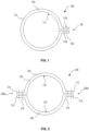
- FIG. 1 shows a first example air hose 100.
- the air hose 100 may be a preconditioned air hose (PCA air hose).
- PCA air hose preconditioned air hose
- the air hose 100 formed of a single sheet 104 that is formed into a tube 102.
- the sheet 104 comprises a woven polyamide fabric and has a weldable surface coating on an inner surface 112 and extending along edge 110a and edge 110b.
- the weldable surface coating is provided across the entire inner surface 112 of the sheet 104, or only along the edge 110a and edge 110b.
- the tube 102 is formed by welding the edge 110a and the edge 110b to each other at a welded seam 106.
- the inner surfaces 112 of the edge 110a and the edge 110b are welded to each other to join the weldable surface coatings and form a welded seam 106.
- the weldable surface coating comprises a thermoplastic, for example a thermoplastic polyurethane or a polyester based urethane coating.
- the welded seam 106 can be formed by pressing together and heating the edge 110a and the edge 110b so that the inner surfaces 112 are welded together. Heated rollers may be used to press and heat the edge 110a and the edge 110b.
- the welded seam 106 creates a seal and is substantially airtight, for example airtight.
- stitches 108 are provided through the welded seam 106.
- the stitches 108 strengthen the welded seam 106 and improve the durability of the air hose 100.
- the stitches 108 do not reduce the airtightness of the tube 102.
- the stitches 108 form a continuous line of stitching along the length of the air hose 100, and in other examples the stitches 108 may be in spaced groups. There may be more than one line of stitches 108 through the welded seam 106, and the lines of stitches 108 may be straight or non-linear.
- Ends of the air hose 100 may be provided with attachment features for joining a first end of the air hose 100 to an air source, for example a preconditioned air unit (PCA unit), and for joining a second end to an aircraft or to a connector for connecting to an aircraft.
- the attachment features may include hook-and-loop fasteners (e.g., Velcro), straps, attachment brackets, or similar.
- FIG. 2 shows a second example air hose 200.
- the air hose 200 may be a preconditioned air hose (PCA air hose).
- the air hose 200 has a first sheet 204 and a second sheet 206 formed into a tube 202.
- the first sheet 204 and the second sheet 206 both comprise a woven polyamide fabric with a weldable surface coating on an inner surface 220.
- the weldable surface coating extends along a first edge 210 and a second edge 212 of the first sheet 204, and along a first edge 214 and a second edge 216 of the second sheet 206.
- the weldable surface coating is provided across the entire inner surfaces 220 of the first sheet 204 and the second sheet 206, or only along the first edge 210, second edge 212, first edge 214, and second edge 216.
- the tube 202 is formed by joining the first edge 210 of the first sheet 204 to the first edge 214 of the second sheet 206 at a first welded seam 208a, and by joining the second edge 212 of the first sheet 204 to the second edge 216 of the second sheet 206 at a second welded seam 208b.
- the inner surfaces 220 of the first sheet 204 and the second sheet 206 are welded along their edges to join the weldable surface coatings and form the first welded seam 208a and the second welded seam 208b.
- the weldable surface coating comprises a thermoplastic, for example a thermoplastic polyurethane or a polyester based urethane coating.
- the first welded seam 208a can be formed by pressing together and heating the first edge 210 of the first sheet 204 and the first edge 214 of the second sheet 206
- the second welded seam 208b can be formed by pressing together and heating the second edge 212 of the first sheet 204 and the second edge 216 of the second sheet 206.
- Heated rollers may be used to press and heat the edges.
- the first welded seam 208a and the second welded seam 208b are sealed and substantially airtight, for example airtight.
- stitches 218 are provided through the first welded seam 208a and the second welded seam 208b.
- the stitches 218 strengthen the first welded seam 208a and the second welded seam 208b and improve the durability of the air hose 200.
- the stitches 218 do not reduce the airtightness of the tube 202.
- the stitches 218 form a continuous line of stitching along the length of the air hose 200, and in other examples the stitches 218 may be in spaced groups. There may be more than one line of stitches 218 through the first welded seam 208a and second welded seam 208b, and the lines of stitches 218 may be straight or non-linear.
- Ends of the air hose 200 may be provided with attachment features for joining a first end of the air hose 200 to an air source, for example a preconditioned air unit (PCA unit), and for joining a second end to an aircraft or to a connector for connecting to an aircraft.
- the attachment features may include hook-and-loop fasteners (e.g., VELCRO closures), straps, attachment brackets, or similar.
- FIG. 3 shows a sheet 300 that may be used as the sheet 104 of the air hose 100 of FIG. 1 , or as the first sheet 204 or second sheet 206 of the air hose 200 of FIG. 2 .
- the sheet 300 is illustrated from an inner surface 310.
- the sheet 300 comprises a woven polyamide fabric, for example Nylon.
- a suitable example material is Cordura (TM) marketed by Invista (TM).
- the sheet 300 extends in a longitudinal direction 308 to a length corresponding to the length of the air hose. As shown, the sheet 300 includes a first edge 302 and a second edge 304. The first edge 302 and the second edge 304 are on opposite sides of the sheet 300. The first edge 302 and the second edge 304 are the edges extending in the longitudinal direction 308.
- a weldable surface coating 306 is provided on the first edge 302 and on the second edge 304.
- the weldable surface coating 306 extends over the entire inner surface 310, or may be limited to the first edge 302 and the second edge 304.
- the weldable surface coating 306 comprises a thermoplastic, for example a thermoplastic polyurethane or a polyester based urethane coating.
- the first edge 302 can be folded over onto the second edge 304 so that their inner surfaces 310 are facing each other, and the first edge 302 and the second edge 304 can then be welded together and optionally stitched.
- a second sheet can be provided that has the same features as the illustrated sheet 300, and edges of the sheet 300 and the second sheet can be welded together as shown in FIG. 2 .
- FIG. 4 shows a cross section through a multilayer material 400 that may be used as the sheet 300 described with reference to FIG. 3 .
- the multilayer material 400 includes an inner surface 412 and a weldable surface coating 306 is provided along the opposite edges of the multilayer material 400 as previously described.
- the multilayer material 400 comprises an inner layer 402, an outer layer 404, and an insulation layer 406.
- the inner layer 402 comprises a woven polyamide fabric, for example Nylon.
- a suitable example material is Cordura (TM) marketed by Invista (TM).
- the inner layer 402 may have a Denier of about 400D.
- the weldable surface coating 306 is provided on the inner layer 402.
- the outer layer 404 also comprises a woven polyamide fabric, for example Nylon.
- a suitable example material is Cordura (TM) marketed by Invista (TM).
- the outer layer 404 may have a Denier of about 1000D, thereby providing suitable protection of the inner layer 402.
- the insulation layer 406 preferably comprises a woven fabric, for example woven polyethylene, and includes a foil 408 facing the inner surface 412.
- the inner layer 402, outer layer 404, and insulation layer 406 may be joined as a laminate material, or joined only in spaced locations.
- the outer layer 404 and the insulation layer 406 may be attached by lines of stitches extending longitudinally along the air hose, and the inner layer 402 may only be joined to the insulation layer 406 at the welded seam(s). Such a construction ensures that the inner layer 402 maintains airtightness and is protected by the outer layer 404 and the insulation layer 406.
- one or more elastic strips 410 may be provided within the multilayer material 400.
- the elastic strips 410 extend longitudinally along the multilayer material 400 (in the longitudinal direction 308 as shown in FIG. 3 ) and help to prevent kinking of the air hose during use.
- the elastic strips 410 may cause the air hose to collapse in a radial direction when not in use (not extended or inflated).
- the elastic strips 410 are preferably joined (e.g., adhered, welded, and/or stitched) to the outer layer 404, particularly an inner surface of the outer layer 404.
- FIG. 5 shows a third example air hose 500.
- the air hose 500 may be a preconditioned air hose (PCA air hose).
- PCA air hose preconditioned air hose
- the air hose 500 may be formed as in air hose 100 or air hose 200, using sheet 300, and/or using multilayer material 400, each as described above.
- FIG. 5 shows a rolled air hose having detail 6, shown in FIG. 6 .
- FIG. 7 shows a cross-section of air hose 500 and FIG. 8 shows a detail of that cross-section.
- air hose 500 may include an inner layer 502 and an outer layer 504 together with an intermediate insulation layer 508, such as foil.
- An outer fabric 520 may be joined along each edge of the air hose 500 to form edges, such as with the stitching described above.
- FIG. 6 shows a detail of an end of air hose 500.
- one or more vent apertures 550 are formed in one or both ends of air hose 500.
- Vent apertures 550 are preferably formed in the outer layer 504 and are preferably arranged close to but not directly along the end of air hose 500.
- the air hose 500 may be rolled up as shown in FIG. 5 and any access trapped air can escape either through an end air hose 500 or through the suitable vent apertures 550.
- the vent apertures 550 may be replaced with a breathable outer layer 504 and/or small apertures throughout an entire length of air hose 500.
- each end of air hose 500 may include sewing lines 515 to close off each end of air hose 500. Vent apertures 550 should not interfere with such sewing lines 515 and are preferably arranged at a distance from each sewing line 515.
- an attachment feature 530 such as a VELCRO closure may be formed at one or both ends of air hose.
- vent apertures 550 described in connection with air hose 500 may be alternatively used in the embodiments of the air hoses 100, 200, sheet 300 and/or multilayer material 400 described above.
Landscapes
- Engineering & Computer Science (AREA)
- Mechanical Engineering (AREA)
- General Engineering & Computer Science (AREA)
- Textile Engineering (AREA)
- Rigid Pipes And Flexible Pipes (AREA)
Abstract
An air hose and a method for making an air hose that includes a woven polyamide fabric having an edge, a weldable surface coating extending along the edge, and a welded seam extending along the edge to form a tube.
Description
- This application claims the benefit of
U.S. Provisional Application, Serial No. 63/540,476, filed on 26 September 2023 - The invention relates to an air hose. In particular, the invention relates to an air hose for delivering air, for example pre-conditioned air, to an aircraft.
- Pre-conditioned air systems are used to bring cooled or heated air into a parked aircraft. Air is supplied from a pre-conditioned air unit to cabins of the aircraft via air hoses, which are referred to as pre-conditioned air hoses, when the aircraft is grounded and an auxiliary power unit is not operational. Such air hoses are often around 18 metres in length, and the pre-conditioned air unit is typically mounted to a passenger boarding bridge at an airport.
- One type of pre-conditioned air hose is a flat air hose that can be flattened when deflated and rolled for storage. This is advantageous as a reel of flattened and rolled hose is relatively small, as compared to other airport equipment. The reel is compact and can be stored easily on the bridge, which is busy with other equipment.
- Embodiments of the invention are now described, by way of example only, hereinafter with reference to the accompanying drawings.
-
FIG. 1 illustrates a first example air hose. -
FIG. 2 illustrates a second example air hose. -
FIG. 3 illustrates an example sheet for forming the air hose ofFIG. 1 or FIG. 2 . -
FIG. 4 illustrates a cross-section of an example multilayer material of the sheet ofFIG. 3 . -
FIG. 5 illustrates a wound air hose according to one embodiment. -
FIG. 6 illustrates a detail of an end of the wound air hose shown inFIG. 5 . -
FIG. 7 illustrates a side cross-section of an air hose according to one embodiment. -
FIG. 8 illustrates a detail of an edge of the air hose shown inFIG. 7 . - Certain terminology is used in the following description for convenience only and is not limiting. The words 'right', 'left', 'lower', 'upper', 'front', 'rear', 'upward', 'down' and 'downward' designate directions in the drawings to which reference is made and are with respect to the described component when assembled and mounted. The words `inner', `inwardly', `outer' and 'outwardly' refer to directions toward and away from, respectively, a designated centreline or a geometric centre of an element being described (e.g. central axis), the particular meaning being readily apparent from the context of the description.
- Further, as used herein, the terms 'connected', 'attached', 'coupled' and 'mounted' are intended to include direct connections between two members without any other members interposed therebetween, as well as, indirect connections between members in which one or more other members are interposed therebetween. The terminology includes the words specifically mentioned above, derivatives thereof, and words of similar import.
- Further, unless otherwise specified, the use of ordinal adjectives, such as, "first", "second" and "third" etc. merely indicate that different instances of like objects are being referred to and are not intended to imply that the objects so described must be in a given sequence, either temporally, spatially, in ranking or in any other manner.
- Like reference numerals are used to depict like features throughout.
-
FIG. 1 shows a firstexample air hose 100. Theair hose 100 may be a preconditioned air hose (PCA air hose). In this example theair hose 100 formed of asingle sheet 104 that is formed into atube 102. Thesheet 104 comprises a woven polyamide fabric and has a weldable surface coating on aninner surface 112 and extending alongedge 110a andedge 110b. In examples, the weldable surface coating is provided across the entireinner surface 112 of thesheet 104, or only along theedge 110a andedge 110b. - As shown, the
tube 102 is formed by welding theedge 110a and theedge 110b to each other at awelded seam 106. In particular, theinner surfaces 112 of theedge 110a and theedge 110b are welded to each other to join the weldable surface coatings and form awelded seam 106. - The weldable surface coating comprises a thermoplastic, for example a thermoplastic polyurethane or a polyester based urethane coating. Accordingly, the
welded seam 106 can be formed by pressing together and heating theedge 110a and theedge 110b so that theinner surfaces 112 are welded together. Heated rollers may be used to press and heat theedge 110a and theedge 110b. Advantageously, thewelded seam 106 creates a seal and is substantially airtight, for example airtight. - As shown, preferably
stitches 108 are provided through thewelded seam 106. Thestitches 108 strengthen thewelded seam 106 and improve the durability of theair hose 100. Advantageously, by providing thestitches 108 within thewelded seam 106 thestitches 108 do not reduce the airtightness of thetube 102. In examples, thestitches 108 form a continuous line of stitching along the length of theair hose 100, and in other examples thestitches 108 may be in spaced groups. There may be more than one line ofstitches 108 through thewelded seam 106, and the lines ofstitches 108 may be straight or non-linear. - Ends of the
air hose 100 may be provided with attachment features for joining a first end of theair hose 100 to an air source, for example a preconditioned air unit (PCA unit), and for joining a second end to an aircraft or to a connector for connecting to an aircraft. The attachment features may include hook-and-loop fasteners (e.g., Velcro), straps, attachment brackets, or similar. -
FIG. 2 shows a secondexample air hose 200. Theair hose 200 may be a preconditioned air hose (PCA air hose). In this example theair hose 200 has afirst sheet 204 and asecond sheet 206 formed into atube 202. Thefirst sheet 204 and thesecond sheet 206 both comprise a woven polyamide fabric with a weldable surface coating on aninner surface 220. The weldable surface coating extends along afirst edge 210 and asecond edge 212 of thefirst sheet 204, and along afirst edge 214 and asecond edge 216 of thesecond sheet 206. In examples, the weldable surface coating is provided across the entireinner surfaces 220 of thefirst sheet 204 and thesecond sheet 206, or only along thefirst edge 210,second edge 212,first edge 214, andsecond edge 216. - As shown, the
tube 202 is formed by joining thefirst edge 210 of thefirst sheet 204 to thefirst edge 214 of thesecond sheet 206 at a firstwelded seam 208a, and by joining thesecond edge 212 of thefirst sheet 204 to thesecond edge 216 of thesecond sheet 206 at a second welded seam 208b. In particular, theinner surfaces 220 of thefirst sheet 204 and thesecond sheet 206 are welded along their edges to join the weldable surface coatings and form the firstwelded seam 208a and the second welded seam 208b. - The weldable surface coating comprises a thermoplastic, for example a thermoplastic polyurethane or a polyester based urethane coating. Accordingly, the first
welded seam 208a can be formed by pressing together and heating thefirst edge 210 of thefirst sheet 204 and thefirst edge 214 of thesecond sheet 206, and the second welded seam 208b can be formed by pressing together and heating thesecond edge 212 of thefirst sheet 204 and thesecond edge 216 of thesecond sheet 206. Heated rollers may be used to press and heat the edges. Advantageously, the firstwelded seam 208a and the second welded seam 208b are sealed and substantially airtight, for example airtight. - As shown, preferably
stitches 218 are provided through the firstwelded seam 208a and the second welded seam 208b. Thestitches 218 strengthen the firstwelded seam 208a and the second welded seam 208b and improve the durability of theair hose 200. Advantageously, by providing thestitches 218 within the firstwelded seam 208a and the second welded seam 208b thestitches 218 do not reduce the airtightness of thetube 202. In examples, thestitches 218 form a continuous line of stitching along the length of theair hose 200, and in other examples thestitches 218 may be in spaced groups. There may be more than one line ofstitches 218 through the first weldedseam 208a and second welded seam 208b, and the lines ofstitches 218 may be straight or non-linear. - Ends of the
air hose 200 may be provided with attachment features for joining a first end of theair hose 200 to an air source, for example a preconditioned air unit (PCA unit), and for joining a second end to an aircraft or to a connector for connecting to an aircraft. The attachment features may include hook-and-loop fasteners (e.g., VELCRO closures), straps, attachment brackets, or similar. -
FIG. 3 shows asheet 300 that may be used as thesheet 104 of theair hose 100 ofFIG. 1 , or as thefirst sheet 204 orsecond sheet 206 of theair hose 200 ofFIG. 2 . Thesheet 300 is illustrated from aninner surface 310. - The
sheet 300 comprises a woven polyamide fabric, for example Nylon. A suitable example material is Cordura (TM) marketed by Invista (TM). - The
sheet 300 extends in alongitudinal direction 308 to a length corresponding to the length of the air hose. As shown, thesheet 300 includes afirst edge 302 and asecond edge 304. Thefirst edge 302 and thesecond edge 304 are on opposite sides of thesheet 300. Thefirst edge 302 and thesecond edge 304 are the edges extending in thelongitudinal direction 308. - As shown, in this example a
weldable surface coating 306 is provided on thefirst edge 302 and on thesecond edge 304. In some examples theweldable surface coating 306 extends over the entireinner surface 310, or may be limited to thefirst edge 302 and thesecond edge 304. - The
weldable surface coating 306 comprises a thermoplastic, for example a thermoplastic polyurethane or a polyester based urethane coating. - To make the
air hose 100 ofFIG. 1 thefirst edge 302 can be folded over onto thesecond edge 304 so that theirinner surfaces 310 are facing each other, and thefirst edge 302 and thesecond edge 304 can then be welded together and optionally stitched. - To make the
air hose 200 ofFIG. 2 a second sheet can be provided that has the same features as theillustrated sheet 300, and edges of thesheet 300 and the second sheet can be welded together as shown inFIG. 2 . -
FIG. 4 shows a cross section through amultilayer material 400 that may be used as thesheet 300 described with reference toFIG. 3 . As shown, themultilayer material 400 includes aninner surface 412 and aweldable surface coating 306 is provided along the opposite edges of themultilayer material 400 as previously described. - The
multilayer material 400 comprises aninner layer 402, anouter layer 404, and aninsulation layer 406. Theinner layer 402 comprises a woven polyamide fabric, for example Nylon. A suitable example material is Cordura (TM) marketed by Invista (TM). Theinner layer 402 may have a Denier of about 400D. Theweldable surface coating 306 is provided on theinner layer 402. - Preferably, the
outer layer 404 also comprises a woven polyamide fabric, for example Nylon. A suitable example material is Cordura (TM) marketed by Invista (TM). Theouter layer 404 may have a Denier of about 1000D, thereby providing suitable protection of theinner layer 402. - The
insulation layer 406 preferably comprises a woven fabric, for example woven polyethylene, and includes afoil 408 facing theinner surface 412. - The
inner layer 402,outer layer 404, andinsulation layer 406 may be joined as a laminate material, or joined only in spaced locations. In some examples, theouter layer 404 and theinsulation layer 406 may be attached by lines of stitches extending longitudinally along the air hose, and theinner layer 402 may only be joined to theinsulation layer 406 at the welded seam(s). Such a construction ensures that theinner layer 402 maintains airtightness and is protected by theouter layer 404 and theinsulation layer 406. - In some examples, as shown, one or more
elastic strips 410 may be provided within themultilayer material 400. In examples, theelastic strips 410 extend longitudinally along the multilayer material 400 (in thelongitudinal direction 308 as shown inFIG. 3 ) and help to prevent kinking of the air hose during use. Theelastic strips 410 may cause the air hose to collapse in a radial direction when not in use (not extended or inflated). Theelastic strips 410 are preferably joined (e.g., adhered, welded, and/or stitched) to theouter layer 404, particularly an inner surface of theouter layer 404. -
FIG. 5 shows a thirdexample air hose 500. Theair hose 500 may be a preconditioned air hose (PCA air hose). In this example theair hose 500 may be formed as inair hose 100 orair hose 200, usingsheet 300, and/or usingmultilayer material 400, each as described above.FIG. 5 shows a rolled air hose having detail 6, shown inFIG. 6 .FIG. 7 shows a cross-section ofair hose 500 andFIG. 8 shows a detail of that cross-section. - Similar to the embodiments described above,
air hose 500 may include aninner layer 502 and anouter layer 504 together with anintermediate insulation layer 508, such as foil. Anouter fabric 520 may be joined along each edge of theair hose 500 to form edges, such as with the stitching described above. -
FIG. 6 shows a detail of an end ofair hose 500. In this detail, it may be appreciated that one ormore vent apertures 550 are formed in one or both ends ofair hose 500.Vent apertures 550 are preferably formed in theouter layer 504 and are preferably arranged close to but not directly along the end ofair hose 500. In such a manner, theair hose 500 may be rolled up as shown inFIG. 5 and any access trapped air can escape either through anend air hose 500 or through thesuitable vent apertures 550. Alternatively, or in addition, thevent apertures 550 may be replaced with a breathableouter layer 504 and/or small apertures throughout an entire length ofair hose 500. - As shown in
FIG. 6 , each end ofair hose 500 may includesewing lines 515 to close off each end ofair hose 500.Vent apertures 550 should not interfere withsuch sewing lines 515 and are preferably arranged at a distance from eachsewing line 515. In addition, and as described above, anattachment feature 530 such as a VELCRO closure may be formed at one or both ends of air hose. - It is understood that the
vent apertures 550 described in connection withair hose 500 may be alternatively used in the embodiments of theair hoses sheet 300 and/ormultilayer material 400 described above. - It will be appreciated by persons skilled in the art that the above detailed examples have been described by way of example only and not in any limitative sense, and that various alterations and modifications are possible without departing from the scope of the invention as defined by the appended claims. Various modifications to the detailed examples described above are possible.
- Through the description and claims of this specification, the words "comprise" and "contain" and variations of them mean "including but not limited to", and they are not intended to (and do not) exclude other moieties, additives, components, integers or steps. Throughout the description and claims of this specification, the singular encompasses the plural unless the context otherwise requires. In particular, where the indefinite article is used, the specification is to be understood as contemplating plurality as well as singularity, unless the context requires otherwise.
- Features, integers, characteristics, compounds, chemical moieties or groups described in conjunction with a particular aspect, embodiment or example of the invention are to be understood to be applicable to any other aspect, embodiment or example described herein unless incompatible therewith. All of the features disclosed in this specification (including any accompanying claims, abstract and drawings), and/or all of the steps of any method or process so disclosed, may be combined in any combination, except combinations where at least some of such features and/or steps are mutually exclusive. The invention is not restricted to the details of any foregoing embodiments. The invention extends to any novel one, or any novel combination, of the features disclosed in this specification (including any accompanying claims, abstract or drawings), or to any novel one, or any novel combination, of the steps of any method or process so disclosed.
Claims (15)
- An air hose comprising a woven polyamide fabric having an edge, a weldable surface coating extending along the edge, and a welded seam extending along the edge to form a tube.
- The air hose of claim 1, comprising a multilayer material having an inner layer and an outer layer, wherein the inner layer comprises the woven polyamide fabric and the weldable surface coating, and wherein the inner layer is welded along the edge to form the welded seam.
- The air hose of claim 2, wherein the outer layer comprises a woven polyamide fabric.
- The air hose of Claim 2 further comprising one or more vent apertures arranged in the outer layer toward at least one end of the air hose.
- The air hose of claim 2, wherein the multilayer material further comprises an insulation layer between the inner layer and the outer layer.
- The air hose of claim 5, wherein the insulation layer comprises a foil.
- The air hose of claim 1, wherein the weldable surface coating comprises a thermoplastic, for example a thermoplastic polyurethane, or a polyester based urethane coating.
- The air hose of claim 1, wherein the woven polyamide fabric comprises a first edge and a second edge, each of the first edge and the second edge comprising the weldable surface coating, and wherein the first edge is welded to the second edge to form the welded seam.
- The air hose of claim 1, comprising a first sheet and a second sheet, each of the first sheet and the second sheet comprising the woven polyamide fabric, wherein each of the first sheet and the second sheet comprise a weldable surface coating extending along a first edge and a second edge, wherein the first edge of the first sheet is welded to the first edge of the second sheet to form a first welded seam, and wherein the second edge of the first sheet is welded to the second edge of the second sheet to form a second welded seam.
- The air hose of claim 1, wherein the welded seam further comprises stitches, optionally wherein the stitches extend substantially continuously along the welded seam.
- The air hose of claim 1, further comprising one or more vent apertures arranged along at least one end of the air hose.
- A method of manufacturing an air hose, the method comprising:providing a woven polyamide fabric having an edge and a weldable surface coating extending along the edge, andforming a tube by welding the edge to form a welded seam extending along the edge.
- The method of claim 12, comprising:providing a first sheet and a second sheet, each of the first sheet and the second sheet comprising the woven polyamide fabric, a first edge, a second edge, and a weldable surface coating extending along the first edge and the second edge,welding the first edge of the first sheet to the first edge of the second sheet to form a first welded seam, andwelding the second edge of the first sheet to the second edge of the second sheet to form a second welded seam.
- The method of claim 12, further comprising stitching through the welded seam.
- The method of claim 12, further comprising providing one or more vent apertures along at least one end of the air hose.
Applications Claiming Priority (2)
| Application Number | Priority Date | Filing Date | Title |
|---|---|---|---|
| US202363540476P | 2023-09-26 | 2023-09-26 | |
| US18/890,140 US20250102085A1 (en) | 2023-09-26 | 2024-09-19 | Air hose |
Publications (1)
| Publication Number | Publication Date |
|---|---|
| EP4530058A1 true EP4530058A1 (en) | 2025-04-02 |
Family
ID=92895646
Family Applications (1)
| Application Number | Title | Priority Date | Filing Date |
|---|---|---|---|
| EP24202058.4A Pending EP4530058A1 (en) | 2023-09-26 | 2024-09-23 | Air hose |
Country Status (3)
| Country | Link |
|---|---|
| US (1) | US20250102085A1 (en) |
| EP (1) | EP4530058A1 (en) |
| CN (1) | CN119712973A (en) |
Citations (4)
| Publication number | Priority date | Publication date | Assignee | Title |
|---|---|---|---|---|
| CN1895698A (en) * | 2006-06-22 | 2007-01-17 | 公安部上海消防研究所 | Movable gas-filled positive-pressure fire-proofing station |
| US20110209792A1 (en) * | 2007-02-01 | 2011-09-01 | Illinois Tool Works Inc. | Robust preconditioned air hose |
| US9689512B2 (en) * | 2009-02-20 | 2017-06-27 | Hobart Brothers Company | Air hose delivery assembly with inner liner |
| US11549726B2 (en) * | 2017-03-07 | 2023-01-10 | E-Tube Sweden Ab | Flexible sealing tube and method for producing the same |
-
2024
- 2024-09-19 US US18/890,140 patent/US20250102085A1/en active Pending
- 2024-09-23 EP EP24202058.4A patent/EP4530058A1/en active Pending
- 2024-09-25 CN CN202411342127.1A patent/CN119712973A/en active Pending
Patent Citations (4)
| Publication number | Priority date | Publication date | Assignee | Title |
|---|---|---|---|---|
| CN1895698A (en) * | 2006-06-22 | 2007-01-17 | 公安部上海消防研究所 | Movable gas-filled positive-pressure fire-proofing station |
| US20110209792A1 (en) * | 2007-02-01 | 2011-09-01 | Illinois Tool Works Inc. | Robust preconditioned air hose |
| US9689512B2 (en) * | 2009-02-20 | 2017-06-27 | Hobart Brothers Company | Air hose delivery assembly with inner liner |
| US11549726B2 (en) * | 2017-03-07 | 2023-01-10 | E-Tube Sweden Ab | Flexible sealing tube and method for producing the same |
Also Published As
| Publication number | Publication date |
|---|---|
| US20250102085A1 (en) | 2025-03-27 |
| CN119712973A (en) | 2025-03-28 |
Similar Documents
| Publication | Publication Date | Title |
|---|---|---|
| US9689512B2 (en) | Air hose delivery assembly with inner liner | |
| CA2677197C (en) | Robust preconditioned air hose | |
| US11780186B1 (en) | Methods for fabricating inflatable devices | |
| US5762740A (en) | Method for building a laminate from an assembly of tire components to form a casing | |
| US6220629B1 (en) | Cushion with increased seam strength and method of assembly | |
| US8485550B2 (en) | Airbag | |
| US3554237A (en) | Insulated wire-reinforced flexible hose | |
| US20050211839A1 (en) | Modularized insulation, systems, apparatus, and methods | |
| US5368341A (en) | Pre-conditioned air hose assembly for aircraft | |
| JP2006503197A (en) | Apparatus and method for guiding seam in seam sealing process | |
| US20150126085A1 (en) | Raft assembly components and methods | |
| US20250102085A1 (en) | Air hose | |
| KR100427155B1 (en) | METHOD AND APPARATUS FOR FORMING A LAMINATE FOR TIRES FROM AN ASSEMBLY OF TIRE COMPONENTS AND FOR CARCINATION | |
| EP0868299B1 (en) | A method and apparatus for building a laminate and forming a carcass subassembly for a tire from unreinforced tire components | |
| US6280548B1 (en) | Method and apparatus for building a laminate and forming a carcass subassembly for a tire | |
| US20210146646A1 (en) | Multilayer protective cover including nonwoven material | |
| CN111853382B (en) | Low-leakage air supply hose of aircraft ground air conditioner and preparation method | |
| US11964463B1 (en) | Sealed reinforced tape | |
| US11890821B1 (en) | Dedicated seam tape and dedicated accessory fabric for inflatable devices | |
| JPH02162134A (en) | Air bag for air bag installation | |
| NZ544222A (en) | Method for continuously producing a coated fabric jacket and a coated fabric jacket produced by said method | |
| JP4095397B2 (en) | Air bag and manufacturing method thereof | |
| EP0152199B1 (en) | Reinforced plastic bags | |
| JP7860265B2 (en) | Airbag manufacturing method with improved internal pressure retention performance | |
| US20230417346A1 (en) | Air hose |
Legal Events
| Date | Code | Title | Description |
|---|---|---|---|
| PUAI | Public reference made under article 153(3) epc to a published international application that has entered the european phase |
Free format text: ORIGINAL CODE: 0009012 |
|
| STAA | Information on the status of an ep patent application or granted ep patent |
Free format text: STATUS: THE APPLICATION HAS BEEN PUBLISHED |
|
| AK | Designated contracting states |
Kind code of ref document: A1 Designated state(s): AL AT BE BG CH CY CZ DE DK EE ES FI FR GB GR HR HU IE IS IT LI LT LU LV MC ME MK MT NL NO PL PT RO RS SE SI SK SM TR |
|
| STAA | Information on the status of an ep patent application or granted ep patent |
Free format text: STATUS: REQUEST FOR EXAMINATION WAS MADE |
|
| 17P | Request for examination filed |
Effective date: 20250929 |