EP4530041A1 - Mold for injection molding of plastic material - Google Patents

Mold for injection molding of plastic material Download PDF

Info

Publication number
EP4530041A1
EP4530041A1 EP24202005.5A EP24202005A EP4530041A1 EP 4530041 A1 EP4530041 A1 EP 4530041A1 EP 24202005 A EP24202005 A EP 24202005A EP 4530041 A1 EP4530041 A1 EP 4530041A1
Authority
EP
European Patent Office
Prior art keywords
shafts
gear
aforesaid
gear wheels
couple
Prior art date
Legal status (The legal status is an assumption and is not a legal conclusion. Google has not performed a legal analysis and makes no representation as to the accuracy of the status listed.)
Pending
Application number
EP24202005.5A
Other languages
German (de)
French (fr)
Inventor
Carlo EBENESTELLI
Current Assignee (The listed assignees may be inaccurate. Google has not performed a legal analysis and makes no representation or warranty as to the accuracy of the list.)
Ivars SpA
Original Assignee
Ivars SpA
Priority date (The priority date is an assumption and is not a legal conclusion. Google has not performed a legal analysis and makes no representation as to the accuracy of the date listed.)
Filing date
Publication date
Application filed by Ivars SpA filed Critical Ivars SpA
Publication of EP4530041A1 publication Critical patent/EP4530041A1/en
Pending legal-status Critical Current

Links

Images

Classifications

    • BPERFORMING OPERATIONS; TRANSPORTING
    • B29WORKING OF PLASTICS; WORKING OF SUBSTANCES IN A PLASTIC STATE IN GENERAL
    • B29CSHAPING OR JOINING OF PLASTICS; SHAPING OF MATERIAL IN A PLASTIC STATE, NOT OTHERWISE PROVIDED FOR; AFTER-TREATMENT OF THE SHAPED PRODUCTS, e.g. REPAIRING
    • B29C33/00Moulds or cores; Details thereof or accessories therefor
    • B29C33/44Moulds or cores; Details thereof or accessories therefor with means for, or specially constructed to facilitate, the removal of articles, e.g. of undercut articles
    • B29C33/442Moulds or cores; Details thereof or accessories therefor with means for, or specially constructed to facilitate, the removal of articles, e.g. of undercut articles with mechanical ejector or drive means therefor
    • B29C33/444Moulds or cores; Details thereof or accessories therefor with means for, or specially constructed to facilitate, the removal of articles, e.g. of undercut articles with mechanical ejector or drive means therefor for stripping articles from a mould core, e.g. using stripper plates
    • B29C33/446Moulds or cores; Details thereof or accessories therefor with means for, or specially constructed to facilitate, the removal of articles, e.g. of undercut articles with mechanical ejector or drive means therefor for stripping articles from a mould core, e.g. using stripper plates and using a rotating movement to unscrew articles
    • BPERFORMING OPERATIONS; TRANSPORTING
    • B29WORKING OF PLASTICS; WORKING OF SUBSTANCES IN A PLASTIC STATE IN GENERAL
    • B29CSHAPING OR JOINING OF PLASTICS; SHAPING OF MATERIAL IN A PLASTIC STATE, NOT OTHERWISE PROVIDED FOR; AFTER-TREATMENT OF THE SHAPED PRODUCTS, e.g. REPAIRING
    • B29C45/00Injection moulding, i.e. forcing the required volume of moulding material through a nozzle into a closed mould; Apparatus therefor
    • B29C45/17Component parts, details or accessories; Auxiliary operations
    • B29C45/26Moulds
    • B29C45/2618Moulds having screw-threaded mould walls
    • BPERFORMING OPERATIONS; TRANSPORTING
    • B29WORKING OF PLASTICS; WORKING OF SUBSTANCES IN A PLASTIC STATE IN GENERAL
    • B29CSHAPING OR JOINING OF PLASTICS; SHAPING OF MATERIAL IN A PLASTIC STATE, NOT OTHERWISE PROVIDED FOR; AFTER-TREATMENT OF THE SHAPED PRODUCTS, e.g. REPAIRING
    • B29C45/00Injection moulding, i.e. forcing the required volume of moulding material through a nozzle into a closed mould; Apparatus therefor
    • B29C45/17Component parts, details or accessories; Auxiliary operations
    • B29C45/26Moulds
    • B29C45/2618Moulds having screw-threaded mould walls
    • B29C45/262Moulds having screw-threaded mould walls provided with unscrewing drive means
    • BPERFORMING OPERATIONS; TRANSPORTING
    • B29WORKING OF PLASTICS; WORKING OF SUBSTANCES IN A PLASTIC STATE IN GENERAL
    • B29CSHAPING OR JOINING OF PLASTICS; SHAPING OF MATERIAL IN A PLASTIC STATE, NOT OTHERWISE PROVIDED FOR; AFTER-TREATMENT OF THE SHAPED PRODUCTS, e.g. REPAIRING
    • B29C45/00Injection moulding, i.e. forcing the required volume of moulding material through a nozzle into a closed mould; Apparatus therefor
    • B29C45/17Component parts, details or accessories; Auxiliary operations
    • B29C45/26Moulds
    • B29C45/2681Moulds with rotatable mould parts
    • BPERFORMING OPERATIONS; TRANSPORTING
    • B29WORKING OF PLASTICS; WORKING OF SUBSTANCES IN A PLASTIC STATE IN GENERAL
    • B29CSHAPING OR JOINING OF PLASTICS; SHAPING OF MATERIAL IN A PLASTIC STATE, NOT OTHERWISE PROVIDED FOR; AFTER-TREATMENT OF THE SHAPED PRODUCTS, e.g. REPAIRING
    • B29C45/00Injection moulding, i.e. forcing the required volume of moulding material through a nozzle into a closed mould; Apparatus therefor
    • B29C45/17Component parts, details or accessories; Auxiliary operations
    • B29C45/26Moulds
    • B29C45/33Moulds having transversely, e.g. radially, movable mould parts
    • BPERFORMING OPERATIONS; TRANSPORTING
    • B29WORKING OF PLASTICS; WORKING OF SUBSTANCES IN A PLASTIC STATE IN GENERAL
    • B29CSHAPING OR JOINING OF PLASTICS; SHAPING OF MATERIAL IN A PLASTIC STATE, NOT OTHERWISE PROVIDED FOR; AFTER-TREATMENT OF THE SHAPED PRODUCTS, e.g. REPAIRING
    • B29C45/00Injection moulding, i.e. forcing the required volume of moulding material through a nozzle into a closed mould; Apparatus therefor
    • B29C45/17Component parts, details or accessories; Auxiliary operations
    • B29C45/26Moulds
    • B29C45/33Moulds having transversely, e.g. radially, movable mould parts
    • B29C45/332Mountings or guides therefor; Drives therefor

Definitions

  • the present invention concerns the technical field of injection molding of plastic material.
  • the invention concerns a mold for producing integral backs for seats or individual so-named up / down systems for fastening backs for seats, and a process of injection molding plastic material by using the aforesaid mold.
  • the known art provides chairs comprising a seat, a back and a pedestal or base, wherein the seat is combined with the back and the base.
  • the back generally made of plastic material, can be a so-named integral back directly combined with the seat at a specific mechanism constrained to the latter, or can be a back combined with the seat via a so-named up / down system for backs, always at the aforesaid specific mechanism of the seat.
  • the fastening of the back to the seat is made by screws which engage a first series of holes provided on the aforesaid mechanism which is generally made of iron.
  • a second series of through holes corresponding to those of the aforesaid first series is also made on the back or on the aforesaid up / down system, wherein the screws, which thus engage the first series of holes and the second series of holes, are locked by respective nuts.
  • the aforesaid nuts are replaced by internally threaded metal inserts which engage the holes of the second series of holes, which holes must thus not necessarily be through holes.
  • the aforesaid metal inserts can be inserted into the back while molding the respective piece, thus resulting embedded in the plastic material of the back, or can be inserted into the back after its molding by manually reworking the piece.
  • a metal plate equipped with threaded holes (the aforesaid second series of holes) is constrained to the back or the respective up / down system, wherein the aforesaid screws are fastened to the metal plate.
  • the technical problem underlying the present invention was to provide a process of injection molding plastic material for molding integral backs for seats or individual so-named up / down systems for fastening backs for seats, which has characteristics such as to overcome one or more of the drawbacks mentioned above with reference to the known art.
  • a mold for injection molding plastic material which is provided with a threading system which automatically makes threaded holes in the molded piece, integral back or up / down system for fastening backs.
  • the aforesaid mold makes the production of backs for seats, whether of so-named integral backs or backs with a so-named up / down system, more economic since the use of additional components for tightening the screws used to combine the back with a respective seat is no longer required, thus avoiding machining the piece following its molding.
  • the aforesaid mold comprises:
  • the aforesaid shafts are components which make the threaded holes on the molded piece through one of the aforesaid threaded end portions, which is identified as first threaded end portion, while the other threaded end portion of each shaft, identified as second threaded end portion, is guided by a respective supporting element by engaging its respective threaded hollow.
  • the aforesaid supporting elements also known as "bushing,” thus constitute guides for the aforesaid shafts, which guides, during a rotary and backward movement of the shafts from the aforesaid first position to the aforesaid second position (unscrewing), advantageously set the forward pitch of the movement, which pitch is preferably equal to 1.25 mm.
  • the aforesaid shafts and the aforesaid supporting elements preferably comprise threads having a pitch of 1.25 mm, corresponding to the distance between two consecutive crests of a respective thread.
  • the aforesaid supporting elements are preferably made of metal material, more preferably bronze.
  • the aforesaid gear wheels of greater diameter of the aforesaid first couple of gear wheels and of the aforesaid second couple of gear wheels of the aforesaid second gear preferably have a different number of teeth and different diameter from one another.
  • the distance between the aforesaid gear wheels of the aforesaid first couple of gear wheels of the aforesaid second gear is preferably different from, and preferably greater than, the distance between the aforesaid gear wheels of the aforesaid second couple of gear wheels of the aforesaid second gear.
  • the positions of the two gear wheels of greater diameter are staggered from one another.
  • the aforesaid six shafts preferably comprise a first series of three shafts identical to one another and a second series of two shafts identical to one another, the sixth shaft not having shafts identical to it.
  • the distance between the gear wheel of a shaft of the aforesaid first series of shafts and a respective end opposite the threaded end portion engaging the respective supporting element is preferably less than a corresponding distance of the gear wheels of the other shafts of the aforesaid six shafts.
  • the gear wheel in each of the shafts of the aforesaid first series of shafts, is preferably closer to the end of the respective first threaded end portion compared to the gear wheels of the other shafts.
  • the position of the gear wheels of the first series of shafts is thus preferably staggered with respect to the positions of the gear wheels of the remaining shafts.
  • the gear wheel of the aforesaid sixth shaft preferably has a diameter greater than the diameter of the gear wheels of the shafts of the aforesaid first series and of the aforesaid second series of shafts.
  • the gear wheel of the aforesaid sixth shaft preferably has a number of teeth greater than the number of teeth of the gear wheels of the shafts of the aforesaid first series and of the aforesaid second series of shafts.
  • the distance between the gear wheel of the aforesaid sixth shaft and the end of the respective first threaded end portion is preferably greater than a corresponding distance of the gear wheels of the other shafts of the aforesaid six shafts.
  • the gear wheel is preferably further from the end of the respective first end portion compared to the gear wheels of the other shafts.
  • the position of the gear wheel of the aforesaid sixth shaft is thus preferably staggered with respect to the positions of the gear wheels of the shafts of the aforesaid first series and of the aforesaid second series of shafts.
  • the aforesaid hollow shape preferably corresponds to the shape of a so-named integral back for seat or to the shape of a so-named up / down system of a back for seat.
  • the aforesaid movement means preferably comprise a hydraulic cylinder with which the aforesaid rack is combined.
  • a process of injection molding plastic material in particular for molding backs or up / down systems of backs for seats, which comprises, in sequence:
  • the aforesaid six threaded holes preferably comprise a first series of three threaded holes arranged according to the vertexes of a first isosceles triangle, and a second series of three threaded holes arranged according to the vertexes of a second isosceles triangle, wherein the heights of the respective bases of the aforesaid first isosceles triangle and of the aforesaid second isosceles triangle lie on the same straight line.
  • Two threaded holes corresponding to two respective vertexes of the aforesaid first isosceles triangle and one threaded hole corresponding to a vertex of the aforesaid second isosceles triangle are preferably made with the shafts of the aforesaid first series of shafts.
  • a mold for the injection molding of plastic material provided with a threading system is denoted by 1.
  • the aforesaid molded piece denoted by 6 corresponds to an integral back and has threaded holes 7.
  • the threading system 5 essentially comprises a rack 8, movement means 9 active on the rack 8 for moving the latter with a reciprocating rectilinear movement, a first gear generally denoted by 10 for converting the aforesaid reciprocating rectilinear motion into rotary motion, a second gear generally denoted by 11 for transmitting the aforesaid rotary motion, a plurality of threaded shafts for making the threaded holes 7, each denoted by 12, and a plurality of supporting elements, in particular one supporting element 13 for each of the shafts 12.

Landscapes

  • Engineering & Computer Science (AREA)
  • Mechanical Engineering (AREA)
  • Manufacturing & Machinery (AREA)
  • Moulds For Moulding Plastics Or The Like (AREA)

Abstract

A mold (1) for injection molding of plastic material is described, comprising a threading system (5) for making threaded holes (7) in a molded piece (6), wherein the threading system comprises a rack (8) movable with a reciprocating rectilinear movement, movement means (9) active on the rack, a first gear (10) comprising a first and a second gearwheel (14, 15) for converting the reciprocating rectilinear motion into rotary motion, a second gear (11) for transmitting the rotary motion, comprising a first and a second couple of gear wheels (16, 17; 18, 19), six shafts (12) parallel to one another and each having a stem (22), opposing threaded end portions (23a, 23b) and a gear wheel (24) coaxial and integral with the stem, wherein the shafts are movable between a first forward position and a second backward position, and six supporting elements (13) each equipped with a threaded hollow (25) engaged by a threaded end portion of a respective shaft.

Description

    Field of the invention
  • In its most general aspect, the present invention concerns the technical field of injection molding of plastic material.
  • In particular, the invention concerns a mold for producing integral backs for seats or individual so-named up/down systems for fastening backs for seats, and a process of injection molding plastic material by using the aforesaid mold.
  • State of the art
  • As known, in the field of home and office furnishings, the known art provides chairs comprising a seat, a back and a pedestal or base, wherein the seat is combined with the back and the base.
  • The back, generally made of plastic material, can be a so-named integral back directly combined with the seat at a specific mechanism constrained to the latter, or can be a back combined with the seat via a so-named up/down system for backs, always at the aforesaid specific mechanism of the seat.
  • In any case, the fastening of the back to the seat is made by screws which engage a first series of holes provided on the aforesaid mechanism which is generally made of iron.
  • According to a first embodiment according to the known art, a second series of through holes corresponding to those of the aforesaid first series is also made on the back or on the aforesaid up/down system, wherein the screws, which thus engage the first series of holes and the second series of holes, are locked by respective nuts.
  • According to a second known embodiment, the aforesaid nuts are replaced by internally threaded metal inserts which engage the holes of the second series of holes, which holes must thus not necessarily be through holes. The aforesaid metal inserts can be inserted into the back while molding the respective piece, thus resulting embedded in the plastic material of the back, or can be inserted into the back after its molding by manually reworking the piece.
  • According to a third known embodiment, at a specific seat, a metal plate equipped with threaded holes (the aforesaid second series of holes) is constrained to the back or the respective up/down system, wherein the aforesaid screws are fastened to the metal plate.
  • Although addressing the purpose, the fastening solutions according to the known art set forth above are not free from drawbacks. For example, all the aforesaid solutions, in addition to the aforesaid screws, require additional components, such as the nuts, the metal inserts or the metal plate. Such additional components required for tightening the screws disadvantageously result in an increase in the final cost of the chair and over time may also result in loosening of the tightness itself, which can compromise the tightness of the back-seat assembly.
  • Summary of the invention
  • The technical problem underlying the present invention was to provide a process of injection molding plastic material for molding integral backs for seats or individual so-named up/down systems for fastening backs for seats, which has characteristics such as to overcome one or more of the drawbacks mentioned above with reference to the known art.
  • According to the invention, the aforesaid problem is solved by a mold for injection molding plastic material, which is provided with a threading system which automatically makes threaded holes in the molded piece, integral back or up/down system for fastening backs.
  • Advantageously, the aforesaid mold makes the production of backs for seats, whether of so-named integral backs or backs with a so-named up/down system, more economic since the use of additional components for tightening the screws used to combine the back with a respective seat is no longer required, thus avoiding machining the piece following its molding.
  • According to the invention, the aforesaid mold comprises:
    • a cavity and a core, wherein at least one of the aforesaid cavity and the aforesaid core is movable, and which define, with the mold closed, a hollow shape corresponding to a piece to be molded,
    • at least one inlet channel arranged at the aforesaid cavity or the aforesaid core for injecting melted plastic material into the aforesaid hollow shape,
    • characterized by comprising a threading system for making threaded holes in the molded piece, wherein the aforesaid threading system comprises:
      • a rack,
      • movement means active on the aforesaid rack for moving the latter with a reciprocating rectilinear movement,
      • a first gear for converting the aforesaid reciprocating rectilinear motion into rotary motion, wherein the aforesaid first gear comprises a first gear wheel and a second gear wheel coaxial and integral with one another, wherein the aforesaid first gear wheel, which has a radius smaller than the radius of the aforesaid second gear wheel, is geared with the aforesaid rack,
      • a second gear for transmitting the aforesaid rotary motion, comprising a first couple of gear wheels and a second couple of gear wheels, wherein the gear wheels of each couple of gear wheels, which are coaxial and integral with one another, have different radii from one another, wherein the gear wheels of smaller diameter of each couple of gear wheels are geared with the aforesaid second gear wheel of the aforesaid first gear,
      • six shafts parallel to one another, each having a stem, opposing threaded end portions (i.e. a first threaded end portion and a second threaded end portion opposite the first threaded end portion), and a gear wheel coaxial and integral with the stem, wherein the aforesaid shafts are movable between a first forward position and a second backward position, wherein the gear wheels of three shafts of the aforesaid six shafts are geared with the gear wheel of greater diameter of the aforesaid first couple of gear wheels of the aforesaid second gear and the gear wheels of the other three shafts of the aforesaid six shafts are geared with the gear wheel of greater diameter of the aforesaid second couple of gear wheels of the aforesaid second gear, and
      • six supporting elements, a supporting element for each of the aforesaid six shafts, wherein each of the aforesaid supporting elements is equipped with a threaded hollow engaged by a threaded end portion of a respective shaft, wherein
      • the aforesaid opposing threaded end portions of each of the aforesaid six shafts have a thread equal to one another and corresponding to the thread of the aforesaid supporting elements.
  • The expression "coaxial" denotes that the gear wheels or the shafts to which it refers have a common rotation axis.
  • In practice, the aforesaid shafts are components which make the threaded holes on the molded piece through one of the aforesaid threaded end portions, which is identified as first threaded end portion, while the other threaded end portion of each shaft, identified as second threaded end portion, is guided by a respective supporting element by engaging its respective threaded hollow.
  • The aforesaid supporting elements, also known as "bushing," thus constitute guides for the aforesaid shafts, which guides, during a rotary and backward movement of the shafts from the aforesaid first position to the aforesaid second position (unscrewing), advantageously set the forward pitch of the movement, which pitch is preferably equal to 1.25 mm. Thus, the aforesaid shafts and the aforesaid supporting elements preferably comprise threads having a pitch of 1.25 mm, corresponding to the distance between two consecutive crests of a respective thread.
  • The aforesaid supporting elements are preferably made of metal material, more preferably bronze.
  • The aforesaid gear wheels of greater diameter of the aforesaid first couple of gear wheels and of the aforesaid second couple of gear wheels of the aforesaid second gear preferably have a different number of teeth and different diameter from one another.
  • The distance between the aforesaid gear wheels of the aforesaid first couple of gear wheels of the aforesaid second gear is preferably different from, and preferably greater than, the distance between the aforesaid gear wheels of the aforesaid second couple of gear wheels of the aforesaid second gear.
  • In practice, in the aforesaid second gear, which has the purpose of transmitting and subdividing the rotary motion from the aforesaid first gear to the aforesaid shafts, the positions of the two gear wheels of greater diameter are staggered from one another.
  • The aforesaid six shafts preferably comprise a first series of three shafts identical to one another and a second series of two shafts identical to one another, the sixth shaft not having shafts identical to it.
  • The distance between the gear wheel of a shaft of the aforesaid first series of shafts and a respective end opposite the threaded end portion engaging the respective supporting element is preferably less than a corresponding distance of the gear wheels of the other shafts of the aforesaid six shafts. In other words, in each of the shafts of the aforesaid first series of shafts, the gear wheel is preferably closer to the end of the respective first threaded end portion compared to the gear wheels of the other shafts. The position of the gear wheels of the first series of shafts is thus preferably staggered with respect to the positions of the gear wheels of the remaining shafts.
  • The gear wheel of the aforesaid sixth shaft preferably has a diameter greater than the diameter of the gear wheels of the shafts of the aforesaid first series and of the aforesaid second series of shafts.
  • The gear wheel of the aforesaid sixth shaft preferably has a number of teeth greater than the number of teeth of the gear wheels of the shafts of the aforesaid first series and of the aforesaid second series of shafts.
  • The distance between the gear wheel of the aforesaid sixth shaft and the end of the respective first threaded end portion is preferably greater than a corresponding distance of the gear wheels of the other shafts of the aforesaid six shafts. In other words, in the aforesaid sixth shaft, the gear wheel is preferably further from the end of the respective first end portion compared to the gear wheels of the other shafts. The position of the gear wheel of the aforesaid sixth shaft is thus preferably staggered with respect to the positions of the gear wheels of the shafts of the aforesaid first series and of the aforesaid second series of shafts.
  • According to the above, the aforesaid hollow shape preferably corresponds to the shape of a so-named integral back for seat or to the shape of a so-named up/down system of a back for seat.
  • The aforesaid movement means preferably comprise a hydraulic cylinder with which the aforesaid rack is combined.
  • According to what is set forth above and according to the present invention, the aforesaid problem is further solved by a process of injection molding plastic material, in particular for molding backs or up/down systems of backs for seats, which comprises, in sequence:
    • an injecting step in which melted plastic material is injected into a mold of the aforesaid type;
    • a forming step in which the melted plastic material is shaped;
    • a cooling step in which the plastic material cools, thus forming a molded piece;
    • a threading step in which the aforesaid shafts of the mold are moved from the aforesaid first forward position to the aforesaid second backward position by means of a dual rotary and backward movement thus defining, in the molded piece, six threaded holes;
    • an opening step for opening the aforesaid mold; and
    • an ejecting step wherein the molded piece is ejected from the aforesaid mold.
  • The aforesaid six threaded holes preferably comprise a first series of three threaded holes arranged according to the vertexes of a first isosceles triangle, and a second series of three threaded holes arranged according to the vertexes of a second isosceles triangle, wherein the heights of the respective bases of the aforesaid first isosceles triangle and of the aforesaid second isosceles triangle lie on the same straight line.
  • Two threaded holes corresponding to two respective vertexes of the aforesaid first isosceles triangle and one threaded hole corresponding to a vertex of the aforesaid second isosceles triangle are preferably made with the shafts of the aforesaid first series of shafts.
  • Brief description of the figures
  • Further characteristics and advantages of the invention will become clearer in the review of the following detailed description of a preferred, although not exclusive, embodiment illustrated by way of example and without limitations with the aid of the accompanying drawings, in which:
    • figure 1 schematically shows a sectional side view of a mold for injection molding plastic material for making a back for a seat, wherein the mold comprises a cavity and a core and a threading system for making threaded holes in the aforesaid back, according to the present invention;
    • figure 2 shows a plan view of the aforesaid cavity of the mold of figure 1;
    • figure 3 shows a perspective view of the aforesaid threading system of the mold of figure 1;
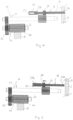
    • figures 4 and 5 show a side view of a detail of the threading system of figure 3, during two respective use steps of the mold of figure 1;
    • figure 6 shows a front transparent view of a detail of the threading system of figure 3;
    • figure 7 shows a front view of a detail of the aforesaid back for seat, comprising six threaded holes.
    Detailed description of the invention
  • With reference to figures 1-7, a mold for the injection molding of plastic material provided with a threading system, according to the present invention, is denoted by 1.
  • The aforesaid threading system automatically makes threaded holes in the molded piece which, according to the invention, can be a so-named integral back or a so-named up/down system of a back for seat.
  • In detail, the mold 1 essentially comprises a cavity 2 and a core 3, wherein at least one of the cavity and the core is movable and which define, with the mold closed, a hollow shape 4 corresponding to the piece to be molded, at least one inlet channel arranged at the cavity or core for injecting melted plastic material into the hollow shape 4, and the aforesaid threading system for making threaded holes in the molded piece, generally denoted by 5.
  • In the examples of the aforesaid figures, the aforesaid molded piece denoted by 6 corresponds to an integral back and has threaded holes 7.
  • According to the invention, the threading system 5 essentially comprises a rack 8, movement means 9 active on the rack 8 for moving the latter with a reciprocating rectilinear movement, a first gear generally denoted by 10 for converting the aforesaid reciprocating rectilinear motion into rotary motion, a second gear generally denoted by 11 for transmitting the aforesaid rotary motion, a plurality of threaded shafts for making the threaded holes 7, each denoted by 12, and a plurality of supporting elements, in particular one supporting element 13 for each of the shafts 12.
  • In detail, the first gear 10 comprises a first gear wheel 14 and a second gear wheel 15 which are coaxial and integral with one another, wherein the first gear wheel 14 has a radius smaller than the radius of the second gear wheel 15, and wherein the first gear wheel 14 is geared with the rack 8.
  • The second gear 11 comprises a first couple of gear wheels denoted by 16 and 17, and a second couple of gear wheels denoted by 18 and 19, wherein the gear wheels of each couple of gear wheels, which are coaxial and integral with one another, have different radii from one another, wherein the gear wheels of smaller diameter 16, 18 of each couple of gear wheels are geared with the aforesaid second gearwheel 15 of the aforesaid first gear 10.
  • In practice, the gear wheels of the first gear 10 and the gear wheels of the second gear 11 are mounted on, and integral with, respective stems 20, 21, as illustrated in the examples of the aforesaid figures.
  • As far as the aforesaid plurality of threaded shafts is concerned, it should be said that it is formed by six shafts 12 parallel to one another, each having a stem 22, opposing threaded end portions 23a and 23b, and a gear wheel 24 coaxial and integral with the stem 22.
  • According to the invention, the shafts 12 are movable between a first forward position and a second backward position and, for the purpose, the gear wheels 24 of three shafts of the six shafts 12 are geared with the gear wheel 17 of greater diameter of the aforesaid first couple of gear wheels of the second gear 11 and the gear wheels 24 of the other three shafts of the six shafts 12 are geared with the gear wheel 19 of greater diameter of the aforesaid second couple of gear wheels of the second gear 11 and, moreover, each of the six supporting elements 13 is equipped with a respective threaded hollow 25 engaged with a threaded end portion of a respective shaft 12.
  • In practice, the shafts 12 are components which make the threaded holes 7 on the threaded piece 6 through one of the aforesaid threaded end portions, which is identified as first threaded end portion 23a, while the other threaded end portion of each shaft, identified as second threaded end portion 23b, is guided by a respective supporting element 13 by engaging its respective threaded hollow 25.
  • The supporting elements 13, which are preferably made of metal material, more preferably of bronze, and which are also known as "bushing," thus constitute guides for the aforesaid thread shafts, which guides, during the rotary and backward movement of the shafts 12 from the aforesaid first forward position to the aforesaid second backward position (unscrewing), advantageously set the forward pitch of the movement, which pitch is preferably equal to 1.25 mm.
  • Thus, the opposing threaded end portions 23a, 23b in each of the six shafts 12 preferably have a thread equal to one another and corresponding to the thread of the respective supporting element 13, which threads preferably have a pitch of 1.25 mm which corresponds to the distance between two consecutive crests of a respective thread.
  • According to the examples of the figures, it should be said that the gear wheels of greater diameter of the aforesaid first couple of gear wheels and of the aforesaid second couple of gear wheels of the second gear 11, i.e. the gear wheels 17 and 19, respectively, preferably have a different number of teeth and a different diameter from one another.
  • Moreover, the distance between the two gear wheels 16, 17 of the first couple of gear wheels of the second gear 11 is preferably different from, and in particular greater than, the distance between the two gear wheels 18, 19 of the second couple of gear wheels of the second gear 11.
  • In practice, in the second gear 11, which has the purpose of transmitting and subdividing the rotary motion from the first gear 10 to the shafts 12, the positions of the two gear wheels 17, 19 of greater diameter are staggered from one another, the gear wheel 17 of the first couple of gear wheels being closer to the end of the respective first threaded end portion 23a than the gear wheel 19 of the second couple of gear wheels.
  • According to the examples of the figures, it should be added that the six shafts 12 preferably comprise a first series of three shafts 12a identical to one another and a second series of two shafts 12b identical to one another, the sixth shaft not having shafts identical to it.
  • Still, as far as the shafts 12 are concerned, it should be said that the distance between the gear wheel 24 of a shaft 12a of the aforesaid first series of shafts and the end of the respective first threaded end portion 23a, i.e. the end opposite the respective supporting element 13, is preferably less than a corresponding distance of the gear wheels in the other three shafts of the six shafts 12. In other words, in each of the shafts 12a of the aforesaid first series of shafts, the gear wheel 24 is preferably closer to the end of the respective first threaded end portion 23a compared to the gear wheels of the other shafts and, therefore, the position of the gear wheels 24 of the shafts 12a of the first series of shafts is preferably staggered with respect to the positions of the gear wheels of the remaining shafts.
  • Moreover, the gear wheel 24 of the aforesaid sixth shaft preferably has a diameter greater than the diameter of the gear wheels of the shafts of the aforesaid first series and the aforesaid second series of shafts.
  • Moreover, the gear wheel 24 of the aforesaid sixth shaft preferably has a number of teeth greater than the number of teeth of the gear wheels of the shafts of the aforesaid first series and the aforesaid second series of shafts.
  • Moreover, the distance between the gear wheel 24 of the aforesaid sixth shaft and the end of the respective first threaded end portion 23a, i.e. the end opposite the respective supporting element 13, is preferably greater than a corresponding distance of the gear wheels in the other five shafts. In other words, in the aforesaid sixth shaft, the gear wheel is preferably further from the end of the respective first threaded end portion compared to the gear wheels of the other shafts. The position of the gear wheel of the aforesaid sixth shaft is thus preferably staggered with respect to the positions of the gear wheels of the shafts of the aforesaid first series and of the aforesaid second series of shafts.
  • As far as the aforesaid movement means 9 are concerned, it should be said that they preferably comprise a hydraulic cylinder with which the aforesaid rack is combined, the possibility of providing different movements means, for example electric, not however being excluded. When the movement means comprise a hydraulic cylinder, the forward and backward movement of the rack is achieved by means of pressurized oil.
  • According to what is set forth above, the present invention further provides a process of injection molding plastic material for molding, by means of a mold of the type considered above, integral backs or up/down systems for fastening backs for seats, which comprises, in sequence:
    • an injecting step in which melted plastic material is injected into the mold 1;
    • a forming step in which the melted plastic material is shaped;
    • a cooling step in which the plastic material cools, thus forming the molded piece 6;
    • a threading step in which the shafts 12 of the threading system 5 of the mold are moved from the aforesaid first forward position to the aforesaid second backward position by means of a dual rotary and backward movement thus defining, in the molded piece 6, six threaded holes 7;
    • an opening step for opening the mold 1; and
    • an ejecting step wherein the molded piece 6 is ejected from the mold 1.
  • In practice, at the beginning of the molding cycle, the six threaded shafts are in the forward position, so as to form the six threaded holes on the molded piece. In particular, after having filled the hollow of the mold with the plastic material, the first threaded end portions of the six threaded shafts are completely enveloped by the melted plastic material which solidifies once cooled, thus forming the threaded holes on the molded piece. Once the cooling step is completed, the unscrewing step is carried out before opening the mold, specifically the so-named hydraulic unscrewing step in which the six threaded shafts move backward and rotate, thus releasing the threaded holes on the molded piece.
  • In particular, the threaded shafts move backward following the pattern of the screw-shaped profile created in the molded piece and thus make a backward rotation. In particular, the two synchronized rotary and backward movements occur in the following way:
    • The rotation originates in the movement means which, via the rack, transmit the motion to the first gear and thus to the second gear, which in turn transmits it to the threaded shafts;
    • The backward movement of each threaded shaft is guided by a respective supporting element, or bushing which, having the same thread made on the threaded shaft, makes the threaded shaft move backward of a pitch of the thread for each revolution completed. Thus, the threaded shaft moves 1.25 mm backward for each revolution.
  • Once the threaded shafts have moved backward, i.e. after the molded piece has been, so-to-speak, released from the six threaded shafts, the mold is opened and the molded piece is ejected.
  • The six threaded holes 7 preferably comprise a first series of three threaded holes 7a arranged according to the vertexes of a first isosceles triangle A, and a second series of three threaded holes 7b arranged according to the vertexes of a second isosceles triangle B, wherein the heights of the respective bases of the first isosceles triangle A and of the second isosceles triangle B lie on the same straight line X.
  • According to the invention, it should be said that two threaded holes corresponding to two respective vertexes of the first isosceles triangle A and a threaded hole corresponding to a vertex of the second isosceles triangle B are preferably made with the shafts 12a of the aforesaid first series of shafts.
  • The advantages of the present invention, which are made clear in the description set forth above, can be summarized by noting that a mold for the injection molding of plastic material, which generally makes the production of backs for seats, whether of so-named integral backs or backs with the so-named up/down system, more economic overall is provided, since the use of additional components for tightening the screws used to combine the back with a respective seat is no longer required, and avoids machining of the piece following its molding.
  • The present mold, together with the process according to the present invention, further allows to improve the quality of the molded pieces.
  • In order to meet contingent and specific needs, a technician of the field can make numerous changes and modifications to the present invention in the embodiments shown and described, all thereby comprised in the protection scope of the invention as defined by the following claims.

Claims (13)

  1. Mold (1) for injection molding of plastic material, comprising:
    a cavity (2) and a core (3), wherein at least one of said cavity (2) and said core (3) is movable, and which define, with the mold closed, a hollow shape (4) corresponding to a piece to be molded,
    at least one inlet channel for injecting melted plastic material into said hollow shape (4),
    characterized by comprising a threading system (5) for making threaded holes (7) in a molded piece (6), wherein said threading system (5) comprises
    a rack (8),
    movement means (9) active on said rack (8) for moving the latter with a reciprocating rectilinear movement,
    a first gear (10) for converting said reciprocating rectilinear motion into rotary motion, comprising a first gear wheel (14) and a second gear wheel (15) coaxial and integral with one another, wherein said first gear wheel (14), which has a radius smaller than the radius of said second gear wheel (15), is geared with said rack (8),
    a second gear (11) for transmitting said rotary motion, comprising a first couple of gear wheels (16, 17) and a second couple of gear wheels (18,19), wherein the gear wheels of each couple of gear wheels, which are coaxial with one another and which have different radii from one another, are integral with one another, wherein the gear wheels (16, 18) of smaller diameter of each couple of gear wheels are geared with said second gear wheel of said first gear (15),
    six shafts (12) parallel to one another, each having a stem (22), a first threaded end portion (23a) and an opposing second threaded end portion (23b), and a gear wheel (24) coaxial and integral with the stem (22), wherein said shafts (12) are movable between a first forward position and a second backward position, wherein the gear wheels (24) of three shafts (12a) of said six shafts (12) are geared with the gear wheel (17) of greater diameter of said first couple of gear wheels of said second gear (11) and the gear wheels of the other three shafts of said six shafts are geared with the gear wheel (19) of greater diameter of said second couple of gearwheels of said second gear (11), and
    six supporting elements (13), a supporting element for each of said six shafts (12), wherein each supporting element (13) is equipped with a threaded hollow (25) engaged by the second threaded end portion (23b) of a respective shaft, wherein
    said opposing first and second threaded end portions (23a, 23b) of each of said six shafts (12) have a thread equal to one another and corresponding to the thread of said supporting elements (13).
  2. Mold according to claim 1, wherein the gearwheels (17, 19) of greater diameter of said first couple of gear wheels and said second couple of gear wheels of said second gear (11) have a different number of teeth and different diameter from one another.
  3. Mold according to claim 1 or 2, wherein the distance between the gear wheels (16, 17) of said first couple of gear wheels is different from the distance between the gear wheels (18, 19) of said second couple of gear wheels of said second gear (11).
  4. Mold according to any one of the preceding claims, wherein said six shafts (12) comprise a first series of three shafts (12a) identical to one another and a second series of two shafts (12b) identical to one another, the sixth shaft not having shafts identical to it.
  5. Mold according to claim 4, wherein the distance between the gear wheel (24) of a shaft (12a) of said first series of shafts and an end of the respective first threaded end portion (23a) is less than a corresponding distance of the gear wheels (24) of the other shafts of said six shafts (12).
  6. Mold according to claim 4 or 5, wherein the gear wheel (24) of said sixth shaft has a diameter greater than the diameter, and a number of teeth greater than the number of teeth, respectively, of the gear wheels (24) of the shafts (12a, 12b) of said first series and said second series of shafts.
  7. Mold according to claim 4, 5 or 6, wherein the distance between the gear wheel (24) of said sixth shaft and an end of the respective first threaded end portion is greater than a corresponding distance of the gear wheels (24) of the other shafts of said six shafts (12).
  8. Mold according to any one of the preceding claims, wherein said hollow shape (4) corresponds to the shape of a back for a seat or to the shape of an up/down system of a back for a seat.
  9. Mold according to any one of the preceding claims, wherein said movement means (9) comprise a hydraulic cylinder to which said rack (8) is combined.
  10. Mold according to any one of the preceding claims, wherein said shafts (12) and said supporting elements (13) comprise threads having a pitch of 1.25 mm.
  11. Process of injection molding plastic material, comprising, in sequence:
    an injecting step in which melted plastic material is injected into a mold (1) according to any one of the preceding claims;
    a forming step in which the melted plastic material is shaped;
    a cooling step in which the plastic material cools, thus forming a molded piece (6);
    a threading step in which said shafts (12) are moved from said first forward position to said second backward position by means of a rotary and backward movement thus defining, in said molded piece (6), six threaded holes (7);
    an opening step for opening said mold (1); and
    an ejecting step wherein said molded piece (6) is ejected from said mold.
  12. Process according to claim 11, wherein said six threaded holes (7) comprise a first series of three threaded holes (7a) arranged according to the vertexes of a first isosceles triangle (A), and a second series of three threaded holes (7b) arranged according to the vertexes of a second isosceles triangle (B), wherein the heights of the respective bases of said first isosceles triangle (A) and said second isosceles triangle (B) lie on the same straight line (X).
  13. Process according to claim 12, wherein two threaded holes corresponding to two respective vertexes of said first isosceles triangle (A) and one threaded hole corresponding to a vertex of said second isosceles triangle (B) are made with the shafts (12a) of said first series of shafts.
EP24202005.5A 2023-09-28 2024-09-23 Mold for injection molding of plastic material Pending EP4530041A1 (en)

Applications Claiming Priority (1)

Application Number Priority Date Filing Date Title
IT102023000020034A IT202300020034A1 (en) 2023-09-28 2023-09-28 PLASTIC INJECTION MOLDING MOLD

Publications (1)

Publication Number Publication Date
EP4530041A1 true EP4530041A1 (en) 2025-04-02

Family

ID=88965180

Family Applications (1)

Application Number Title Priority Date Filing Date
EP24202005.5A Pending EP4530041A1 (en) 2023-09-28 2024-09-23 Mold for injection molding of plastic material

Country Status (2)

Country Link
EP (1) EP4530041A1 (en)
IT (1) IT202300020034A1 (en)

Citations (2)

* Cited by examiner, † Cited by third party
Publication number Priority date Publication date Assignee Title
US20060131787A1 (en) * 2004-12-20 2006-06-22 Gerald Seidelman Apparatus for making threaded articles in a plastic injection molding process
CN102371661A (en) * 2010-08-09 2012-03-14 株式会社日本制钢所 Demolding device and injection molding machine

Patent Citations (2)

* Cited by examiner, † Cited by third party
Publication number Priority date Publication date Assignee Title
US20060131787A1 (en) * 2004-12-20 2006-06-22 Gerald Seidelman Apparatus for making threaded articles in a plastic injection molding process
CN102371661A (en) * 2010-08-09 2012-03-14 株式会社日本制钢所 Demolding device and injection molding machine

Also Published As

Publication number Publication date
IT202300020034A1 (en) 2025-03-28

Similar Documents

Publication Publication Date Title
CN112659494A (en) Two-plate injection molding machine capable of electrically opening and closing mold
EP4530041A1 (en) Mold for injection molding of plastic material
CN107498777A (en) The folded mould special injection molding of injection among a kind of split shifting formwork of template
EP0076980A2 (en) Multiple injection mould
JPH01148524A (en) Insert type core rotating mold assembly
CN110900971B (en) Double-acting mold demolding injection mold
WO1991003366A1 (en) Modular corrugator
EP2705941B1 (en) Method for the production of blow moulded plastic hollow bodies and multiple extrusion head for carrying out the method
CN214773808U (en) Two-plate injection molding machine capable of electrically opening and closing mold
CN218429708U (en) Hot runner device and injection mold's cover half
CN214294282U (en) Rotatory device of loosing core of arc product and injection mold
CN221136707U (en) Automatic change combination formula mould
CN209580401U (en) A kind of mold automatic threads demoulding mechanism
CN218256413U (en) Double-tooth-core synchronous demoulding mechanism in internal thread injection mould
CN117505577B (en) Aluminum profile production die
CN118385526B (en) Metal flabellum integrated into one piece die casting device
CN208101002U (en) A kind of novel rubber pipe extrusion head
US7214050B2 (en) Adjusting structure of an adjusting seat of an injection molding machine
CN222387514U (en) Injection mold based on rack and pinion rotary mechanism
CN217891673U (en) Forming die of antiseptic solution bottle lid
CN112475055A (en) Stamping die is used in part production that stability is high
CN223058246U (en) Rotary demolding mold
CN217258061U (en) Mould multicavity mould of steerable shaping die cavity injecting glue
CN215849436U (en) Gate internally cutting structure applied to annular insert integrated injection mold
CN222135796U (en) Multi-hole thread die

Legal Events

Date Code Title Description
PUAI Public reference made under article 153(3) epc to a published international application that has entered the european phase

Free format text: ORIGINAL CODE: 0009012

STAA Information on the status of an ep patent application or granted ep patent

Free format text: STATUS: THE APPLICATION HAS BEEN PUBLISHED

AK Designated contracting states

Kind code of ref document: A1

Designated state(s): AL AT BE BG CH CY CZ DE DK EE ES FI FR GB GR HR HU IE IS IT LI LT LU LV MC ME MK MT NL NO PL PT RO RS SE SI SK SM TR

STAA Information on the status of an ep patent application or granted ep patent

Free format text: STATUS: REQUEST FOR EXAMINATION WAS MADE

17P Request for examination filed

Effective date: 20251001