EP4530037A2 - Cartridge and stapler - Google Patents
Cartridge and stapler Download PDFInfo
- Publication number
- EP4530037A2 EP4530037A2 EP25158362.1A EP25158362A EP4530037A2 EP 4530037 A2 EP4530037 A2 EP 4530037A2 EP 25158362 A EP25158362 A EP 25158362A EP 4530037 A2 EP4530037 A2 EP 4530037A2
- Authority
- EP
- European Patent Office
- Prior art keywords
- cartridge
- main body
- lever
- stapler
- fixing shaft
- Prior art date
- Legal status (The legal status is an assumption and is not a legal conclusion. Google has not performed a legal analysis and makes no representation as to the accuracy of the status listed.)
- Pending
Links
Images



Classifications
-
- B—PERFORMING OPERATIONS; TRANSPORTING
- B42—BOOKBINDING; ALBUMS; FILES; SPECIAL PRINTED MATTER
- B42B—PERMANENTLY ATTACHING TOGETHER SHEETS, QUIRES OR SIGNATURES OR PERMANENTLY ATTACHING OBJECTS THERETO
- B42B4/00—Permanently attaching together sheets, quires or signatures by discontinuous stitching with filamentary material, e.g. wire
-
- B—PERFORMING OPERATIONS; TRANSPORTING
- B25—HAND TOOLS; PORTABLE POWER-DRIVEN TOOLS; MANIPULATORS
- B25C—HAND-HELD NAILING OR STAPLING TOOLS; MANUALLY OPERATED PORTABLE STAPLING TOOLS
- B25C5/00—Manually operated portable stapling tools; Hand-held power-operated stapling tools; Staple feeding devices therefor
- B25C5/16—Staple-feeding devices, e.g. with feeding means, supports for staples or accessories concerning feeding devices
- B25C5/1603—Staple-feeding devices, e.g. with feeding means, supports for staples or accessories concerning feeding devices for tools with provision for bending the ends of the staples or to the work
-
- B—PERFORMING OPERATIONS; TRANSPORTING
- B27—WORKING OR PRESERVING WOOD OR SIMILAR MATERIAL; NAILING OR STAPLING MACHINES IN GENERAL
- B27F—DOVETAILED WORK; TENONS; SLOTTING MACHINES FOR WOOD OR SIMILAR MATERIAL; NAILING OR STAPLING MACHINES
- B27F7/00—Nailing or stapling; Nailed or stapled work
- B27F7/17—Stapling machines
- B27F7/38—Staple feeding devices
-
- B—PERFORMING OPERATIONS; TRANSPORTING
- B25—HAND TOOLS; PORTABLE POWER-DRIVEN TOOLS; MANIPULATORS
- B25C—HAND-HELD NAILING OR STAPLING TOOLS; MANUALLY OPERATED PORTABLE STAPLING TOOLS
- B25C5/00—Manually operated portable stapling tools; Hand-held power-operated stapling tools; Staple feeding devices therefor
- B25C5/16—Staple-feeding devices, e.g. with feeding means, supports for staples or accessories concerning feeding devices
- B25C5/1686—Staple-feeding devices, e.g. with feeding means, supports for staples or accessories concerning feeding devices using pre-loaded cassettes
-
- B—PERFORMING OPERATIONS; TRANSPORTING
- B42—BOOKBINDING; ALBUMS; FILES; SPECIAL PRINTED MATTER
- B42B—PERMANENTLY ATTACHING TOGETHER SHEETS, QUIRES OR SIGNATURES OR PERMANENTLY ATTACHING OBJECTS THERETO
- B42B5/00—Permanently attaching together sheets, quires or signatures otherwise than by stitching
Definitions
- the present disclosure relates to a cartridge to be loaded on a stapler and a stapler.
- an electric stapler that automatically performs a binding process by driving a staple into a sheet bundle by a driver mechanism and folding leg portions of the staple penetrating the sheet bundle by a clincher portion.
- the electric stapler is mounted in, for example, an image forming apparatus that forms an image on a sheet or a post-processing apparatus that performs post-processing.
- a cartridge for accommodating a refill in which a plurality of staples are stacked is detachably attached to a stapler main body.
- a method of removing the cartridge from the stapler main body a plurality of methods are adopted. For example, there is a type in which a finger is hooked on a knob of a cartridge and the knob is rotated in a predetermined direction to remove the cartridge from a stapler main body, and a type in which a knob of a cartridge is gripped and pulled out rearward to remove the cartridge from a stapler main body.
- JP2019-089322A discloses a stapler in which an operation unit is rotatably attached to an upper surface of a cartridge main body via a link member, and the operation unit is rotated to take out the cartridge from a stapler main body.
- the cartridge cannot be removed by an operation of gripping the knob and pulling the knob rearward. Further, in a case of the type in which the knob of the cartridge is gripped and pulled, the cartridge cannot be removed by an operation of rotating the knob.
- the knob of the cartridge is operated in a direction different from an original operation direction, not only the cartridge cannot be removed but also the cartridge may be dropped or the cartridge may be damaged.
- the present disclosure provides a cartridge and a stapler capable of realizing various operability in a case of removing the cartridge from a stapler main body.
- a cartridge to be mounted on a stapler includes: a cartridge main body configured to accommodate a staple; a lever attached to the cartridge main body to be displaceable with respect to the cartridge main body; and a fixing portion for fixing the cartridge to the stapler when the cartridge is loaded on the stapler.
- the fixing portion is located at a first position in a fixed state where the cartridge is fixed to the stapler, and is located at a second position in a released state where the fixed state is released.
- the lever has a moving portion that moves the fixing portion to the second position when the lever is displaced in a first direction and a second direction with respect to the cartridge main body.
- a stapler includes: a main body including a loading portion in which a cartridge is loaded and a fixing portion that fixes the cartridge loaded in the loading portion into the loading portion; and a lever attached to the main body to be displaceable with respect to the main body.
- the fixing portion has a protruding portion that is located at a first position in a fixed state where the cartridge is fixed to the loading portion and is located at a second position in a released state where the fixed state of the cartridge is released.
- the lever has a moving portion that moves the protruding portion from the first position to the second position when the lever is displaced in a first direction and a second direction different from the first direction with respect to the main body.
- An electric stapler 1 is mounted, for example, in an image forming apparatus that forms a predetermined image on a sheet or in a post-processing apparatus connected to a downstream side of the image forming apparatus in a sheet transport direction.
- the electric stapler 1 performs a binding process on a sheet bundle including a plurality of sheets on which predetermined images are formed by the image forming apparatus using a staple.
- the electric stapler 1 performs the binding process on the sheet bundle by sequentially performing a clamping step of clamping the sheet bundle, a penetrating step of penetrating a staple through the clamped sheet bundle, and a clinching step of folding leg portions of the staple penetrating the sheet bundle.
- the electric stapler 1 includes a cartridge 20 in which a staple is accommodated, a stapler main body 10 to which the cartridge 20 is detachably attached, and a lever 60 which is provided to the stapler main body 10 so as to be displaceable with respect to the stapler main body 10. Further, the electric stapler 1 includes a driver mechanism 30 that drives a staple toward a sheet bundle, a table 40 that can move up and down with respect to the driver mechanism 30, and a clincher portion 50 that folds leg portions of the staple driven by the driver mechanism 30 and passing through the sheets.
- a side on which the driver mechanism 30 is provided is a front side of the electric stapler 1, and a side on which the lever 60 is provided is a rear side of the electric stapler 1.
- a side on which the table 40 and the clincher portion 50 are provided is referred to as an upper side of the electric stapler 1, and an opposite side is referred to as a lower side.
- a first direction D1 which is a displacement direction of the lever 60, is a gravity direction when the electric stapler 1 is placed on a floor surface, and corresponds to a lower side with respect to the cartridge 20.
- a second direction D2 which is a displacement direction of the lever 60 is a direction opposite to the gravity direction and corresponds to an upper side with respect to the cartridge 20.
- a third direction D3, which is a displacement direction of the lever 60, is a direction opposite to a loading direction D4 when a direction orthogonal to the first direction D1 is defined as the loading direction D4 of the cartridge 20 into the stapler main body 10, and corresponds to a rear side of the electric stapler 1.
- a placement table 70 on which a sheet bundle is placed is provided at a position where the placement table 70 is above the driver mechanism 30 of the stapler main body 10 and faces the table 40.
- the driver mechanism 30 is disposed on the front side in the stapler main body 10, and is configured to be movable up and down with respect to the placement table 70 based on driving of a drive mechanism 32.
- the driver mechanism 30 forms a staple into a substantially U-shape by folding both ends of the staple by a forming plate (not shown), and drives the staple formed into the substantially U-shape toward the sheet bundle.
- the table 40 is disposed to face upper sides of the driver mechanism 30 and the placement table 70.
- the table 40 is connected to the drive mechanism 32 via a frame 12, and is configured to be movable in an approaching direction and a separating direction with respect to the placement table 70 based on the driving of the drive mechanism 32.
- a surface (portion) of the table 40 facing the placement table 70 functions as a clamp portion 80 that clamps the sheet bundle between the surface and the placement table 70.
- the table 40 and the clamp portion 80 are configured to be movable between a clamping position where the sheet bundle is clamped and a home position where the sheet bundle is not clamped.
- the clincher portion 50 is disposed at a front end portion of the table 40 at a position facing the driver mechanism 30. In cooperation with the driver mechanism 30, the clincher portion 50 presses the leg portions of the staple penetrating the sheet bundle and folds the legs portion of the staple inward, thereby binding the sheet bundle by the staple.
- the stapler main body 10 includes the loading portion 110 into which the cartridge 20 is loaded, and engagement portions 120 that engage and fixes the cartridges 20 loaded in the loading portion 110 into the loading portion 110.
- the engagement portions 120 are formed at two positions on one end side and the other end side in a left-right direction of an upper portion of the loading portion 110, and are disposed at positions facing moving portions 603 (to be described later) of the cartridge 20 loaded in the loading portion 110.
- the engagement portion 120 includes a step portion 121 and an inclined surface 122 inclined obliquely downward from an upper end of the step portion 121 toward the rear side.
- the step portion 121 has a flat surface 121a and a substantially vertical surface 121b standing from the flat surface 121a.
- a height of the vertical surface 121b of the step portion 121 is preferably at least equal to or greater than a radius of a fixing shaft 220 in order to prevent the fixing shaft 220, which will be described later, from coming off rearward from the engagement portion 120. Accordingly, when the cartridge 20 is loaded into the stapler main body 10, the fixing shaft 220 of the cartridge 20 is caught (engaged) by the step portion 121, so that a rearward movement of the fixing shaft 220 is restricted, and the cartridge 20 can be locked to the stapler main body 10.
- the cartridge 20 includes a cartridge main body 200, a refill accommodating portion 210 that accommodates a refill, the lever 60 that is attached to the cartridge main body 200 so as to be displaceable with respect to the cartridge main body 200, the fixing shaft 220 for fixing the cartridge 20 to the stapler main body 10 when the cartridge 20 is loaded into the stapler main body 10, a torsion coil spring 250 that urges the fixing shaft 220 to a position where the fixing shaft 220 is engaged with and fixed to the engagement portion 120, and a discharge portion 260 that discharges a staple.
- the refill accommodating portion 210 is provided inside the cartridge main body 200 and includes a space portion having a size capable of accommodating the refill 300.
- An insertion and removal opening 212 (see FIG. 3 ) through which the refill 300 can be inserted into and pulled out from the space portion of the refill accommodating portion 210 is formed in a rear wall of the cartridge main body 200.
- the refill 300 can be loaded into the refill accommodating portion 210 from the rear side of the cartridge main body 200 through the insertion and removal opening 212.
- the refill 300 is formed by a box body capable of accommodating the connected staples to which linear staples are connected. A large number of connected staples are stacked in the refill 300.
- the refill 300 includes a lid member 310 for pressing the uppermost connected staple among the stacked connected staples.
- the lid member 310 is configured to be movable up and down in the refill 300 by increasing or decreasing the number of connected staples in the refill 300.
- the fixing shaft 220 is an example of a protruding portion and a fixing portion, and is disposed above the refill accommodating portion 210 and at a rear portion of the cartridge main body 200 as shown in FIGS. 5 and 6 .
- the protruding portion in the present embodiment is a round bar, but is not limited thereto.
- the protruding portion may be a triangular protrusion or a quadrangular protrusion.
- the fixing shaft 220 is disposed such that a longitudinal direction thereof extends along the left-right direction of the cartridge main body 200.
- the torsion coil spring 250 is attached to a substantially central portion of the fixing shaft 220.
- the torsion coil spring 250 includes coil portions 251, fixed arms 252 each extending from one end side of the coil portion 251 toward a front side of the refill accommodating portion 210, and load arms 253 each extending from the other end side of the coil portion 251 toward the front side of the refill accommodating portion 210.
- the torsion coil spring 250 is an example of an elastic member. Although the torsion coil spring is used in the present embodiment, the elastic member may be a plate spring or a rubber member.
- the fixed arm 252 is located above the load arm 253.
- the torsion coil spring 250 having the two coil portions 251 is used, the fixing shaft 220 is disposed to penetrate the coil portions 251, and the load arms 253 are configured to be substantially in a center in a cartridge left-right direction.
- the configuration of the torsion coil spring 250 is not limited to the configuration of the present embodiment.
- a distal end side of the fixed arm 252 is in contact with the upper wall 202 (see FIG. 2 and the like) of the cartridge main body 200.
- the fixed arm 252 is elastically deformable with a contact point as a fulcrum, and urges the fixing shaft 220 downward on the refill accommodating portion 210 side. Accordingly, as shown in FIG. 4 , both end sides of the fixing shaft 220 abut on opening edges of the moving portions 603 of the lever main body 600, and are disposed at positions where the fixing shaft 220 is engageable with the engagement portions 120.
- the fixing shaft 220 when the fixing shaft 220 is fixed by the engagement portion 120 of the cartridge main body 200, the fixing shaft 220 is located at a first position P1 by an urging force of the torsion coil spring 250.
- the fixing shaft 220 is located at a second position P2 against an elastic force of the torsion coil spring 250 as shown in FIG. 8 .
- the first position P1 is located below the second position P2. After the lock by the engagement portion 120 is released, the fixing shaft 220 moves from the second position to the first position.
- the load arm 253 of the torsion coil spring 250 is provided so as to be abuttable on the upper surface of the lid member 310 of the refill 300 loaded in the refill accommodating portion 210, and urges the lid member 310 downward, which is a bottom wall side of the refill 300. Accordingly, when the refill 300 is loaded into the refill accommodating portion 210, the lid member 310 of the refill 300 is pressed by the load arm 253 of the torsion coil spring 250, and the connected staples accommodated in the refill 300 can be held in a stable posture.
- the torsion coil spring 250 that elastically supports the fixing shaft 220 also serves as an elastic member that presses the lid member 310 of the refill 300.
- the coil portion 251 of the torsion coil spring 250 functions as an elastic member that abuts against the fixing shaft 220 and urges the fixing shaft 220 to the first position P1
- the load arm 253 functions as an elastic member that urges the lid member 310 of the refill 300 to the bottom wall side of the refill 300.
- the discharge portion 260 is disposed in a front portion of the cartridge main body 200.
- the discharge portion 260 folds a staple located at a leading end portion of the connected staples fed out from the refill 300 in a substantially U-shape in cooperation with the driver mechanism 30, and discharges the staple toward the sheet bundle on the placement table 70.
- the lever 60 is attached above the refill accommodating portion 210 and at the rear portion of the cartridge 20 so as to be displaceable with respect to the stapler main body 10.
- the lever 60 is attached to the cartridge main body 200.
- the lever 60 is displaceable relative to the stapler main body 10.
- the lever 60 does not necessarily need to be attached to the cartridge, and may be provided on the stapler main body 10.
- the lever 60 includes a lever main body 600 having distal end portions 601, proximal end portions 602, and the moving portions 603 provided between the distal end portions 601 and the proximal end portions 602, and a knob 610 protruding rearward (in the third direction D3) from the proximal end portion 602.
- the lever main body 600 is configured in a substantially U-shape in which a front side of the stapler main body 10 is opened. Left ends and the right ends of the fixing shaft 220 penetrate the lever main body 600.
- the moving portion 603 supports the fixing shaft 220 such that the fixing shaft 220 is movable from the first position P1 to the second position P2 when the lever 60 is displaced downward in the first direction D1 with respect to the stapler main body 10 (see FIG. 8 ), when the lever 60 is displaced upward in the second direction D2 with respect to the stapler main body 10 (see FIG. 9 ), or when the lever 60 is displaced rearward in the third direction D3 with respect to the stapler main body 10 (see FIG. 10 ).
- the moving portion 603 includes an opening portion. A left end portion (one end portion) of the fixing shaft 220 is movably supported by the moving portion 603 of the left extending portion 600a.
- the right end portion (the other end portion) of the fixing shaft 220 is movably supported by the moving portion of the right extending portion 600b.
- the moving portion 603 has, for example, a substantially triangular shape, and has an inclined surface 603a inclined obliquely upward from the proximal end portion 602 toward the distal end portion 601.
- a corner portion 603b supporting the fixing shaft 220 at the first position P1 is curved along an arc shape of the fixing shaft 220.
- the knob 610 is a portion to be gripped by a user when the cartridge 20 is removed from the stapler main body 10.
- the knob 610 has a substantially U-shape in a plan view, and both end portions thereof are attached to the rear end sides of the lever main body 600.
- a gap S into which fingers can be inserted is provided between the knob 610 and the cartridge main body 200 so that the user can easily grip the knob 610.
- the knob 610 is disposed above the refill accommodating portion 210 and at a rear portion of the cartridge 20, so that an amount of protrusion from the rear wall of the stapler main body 10 is prevented.
- the user grips the knob 610 and rotates or slides the entire lever 60 in any one of the first direction D1, the second direction D2, and the third direction D3, thereby removing the cartridge 20 from the stapler main body 10.
- the cartridge 20 moves forward while sliding on a bottom wall of the loading portion 110 of the stapler main body 10 (see FIG. 3 ).
- the fixing shaft 220 of the cartridge main body 200 moves upward against the elastic force of the fixed arm 252 of the torsion coil spring 250 while sliding on the inclined surface 122 of the engagement portion 120 of the stapler main body 10.
- the fixing shaft 220 climbs over the inclined surface 122 to the step portion 121 side, and as shown in FIG. 7 , the fixing shaft 220 is urged downward by a restoring force of the fixed arm 252 of the torsion coil spring 250 to move to the first position P1. As a result, the fixing shaft 220 is engaged with the step portion 121 of the engagement portion 120, and the cartridge 20 is locked to the stapler main body 10.
- FIG. 8 is a diagram showing an example of an operation of the electric stapler 1 when the lever 60 is rotated in the first direction D1 to remove the cartridge 20 from the stapler main body 10.
- the knob 610 of the lever 60 when the knob 610 of the lever 60 is rotated downward in the first direction D1 by the user in a state where the knob 610 is gripped, the knob 610 side rotates downward (clockwise) about a first fulcrum F1 with respect to the cartridge main body 200.
- the first fulcrum F1 is a point where a proximal end side of a lower surface of the lever main body 600 (the extending portion 600a) and the upper surface of the cartridge main body 200 are in contact with each other, and is located behind the moving portion 603.
- the lever main body 600 side of the lever 60 moves upward, and the fixing shaft 220 supported by the moving portion 603 of the lever main body 600 is pushed up against the elastic force of the torsion coil spring 250.
- the fixing shaft 220 is moved to the second position P2 higher than the step portion 121 of the engagement portion 120, and the fixing shaft 220 is disengaged from the engagement portion 120 of the stapler main body 10.
- FIG. 9 is a diagram showing an example of an operation of the electric stapler 1 when the lever 60 is rotated in the second direction D2 to remove the cartridge 20 from the stapler main body 10.
- the lever 60 when the lever 60 is rotated upward in the second direction D2 by the user in a state where the lever 60 is gripped, the lever 60 rotates upward (counterclockwise) about a second fulcrum F2 with respect to the cartridge main body 200.
- the second fulcrum F2 is a point where a distal end side of the lower surface of the lever main body 600 (the extending portion 600a) and the upper surface of the cartridge main body 200 are in contact with each other, and is located in front of the moving portion 603.
- the fixing shaft 220 supported by the moving portion 603 of the lever 60 is pushed up against the elastic force of the torsion coil spring 250, and the fixing shaft 220 moves to the second position P2 higher than the step portion 121 of the engagement portion 120.
- the fixing shaft 220 is disengaged from the engagement portion 120 of the stapler main body 10.
- FIG. 10 is a diagram showing an example of an operation of the electric stapler 1 when the lever 60 is pulled in the third direction D3 to remove the cartridge 20 from the stapler main body 10.
- one of the three types of operations of the lever 60 in the first direction, the second direction, and the third direction can be selected.
- the knob 610 of the lever 60 is disposed substantially above the refill accommodating portion 210 and at the rear portion of the cartridge 20, the mount of protrusion from the rear wall of the stapler main body 10 is prevented. Accordingly, the electric stapler 1 can be downsized as compared with a configuration of the related art in which the knob 610 protrudes outward from the rear wall of the stapler main body 10.
- the torsion coil spring 250 provided in the cartridge 20 has both the function of urging the fixing shaft 220 to the first position P1 and the function of pressing the lid member 310 of the refill 300, it is possible to reduce the number of components as compared with the case where the elastic member is used for each of the fixing shaft 220 and the lid member 310. Accordingly, it is possible to reduce the cost of the electric stapler 1 including the cartridge 20 compared to the related art.
- the fixing shaft 220 and the lever 60 for fixing and releasing the cartridge 20 to and from the stapler main body 10 are provided on the cartridge 20 side
- the present disclosure is not limited thereto, and the fixing shaft 220 and the lever 60 may be provided on the stapler main body 10 side.
- the electric stapler 1 may include the stapler main body 10 including the loading portion 110 into which the cartridge 20 is loaded and the fixing shaft 220 that fixes the cartridge 20 loaded into the loading portion 110 to the loading portion 110, and the lever 60 attached to the stapler main body 10 so as to be displaceable with respect to the stapler main body 10.
- the fixing shaft 220 has the protruding portion that is located at the first position P1 when the cartridge 20 is fixed to the loading portion 110 and is located at the second position P2 when the fixing of the cartridge 20 is released.
- the lever 60 includes the moving portion 603 that moves the fixing shaft 220 from the first position P1 to the second position P2 when the lever 60 is displaced in the first direction D1, in the second direction D2, and in the third direction D3 with respect to the stapler main body 10.
Landscapes
- Engineering & Computer Science (AREA)
- Mechanical Engineering (AREA)
- Life Sciences & Earth Sciences (AREA)
- Forests & Forestry (AREA)
- Textile Engineering (AREA)
- Portable Nailing Machines And Staplers (AREA)
- Dovetailed Work, And Nailing Machines And Stapling Machines For Wood (AREA)
Abstract
Description
- The present disclosure relates to a cartridge to be loaded on a stapler and a stapler.
- In the related art, there is known an electric stapler that automatically performs a binding process by driving a staple into a sheet bundle by a driver mechanism and folding leg portions of the staple penetrating the sheet bundle by a clincher portion.
- The electric stapler is mounted in, for example, an image forming apparatus that forms an image on a sheet or a post-processing apparatus that performs post-processing.
- A cartridge for accommodating a refill in which a plurality of staples are stacked is detachably attached to a stapler main body. As a method of removing the cartridge from the stapler main body, a plurality of methods are adopted. For example, there is a type in which a finger is hooked on a knob of a cartridge and the knob is rotated in a predetermined direction to remove the cartridge from a stapler main body, and a type in which a knob of a cartridge is gripped and pulled out rearward to remove the cartridge from a stapler main body.
-
JP2019-089322A - However, in a case of the type of the related art in which the knob of the cartridge of
JP2019-089322A - The present disclosure provides a cartridge and a stapler capable of realizing various operability in a case of removing the cartridge from a stapler main body.
- According to an illustrative aspect of the present disclosure, a cartridge to be mounted on a stapler includes: a cartridge main body configured to accommodate a staple; a lever attached to the cartridge main body to be displaceable with respect to the cartridge main body; and a fixing portion for fixing the cartridge to the stapler when the cartridge is loaded on the stapler. The fixing portion is located at a first position in a fixed state where the cartridge is fixed to the stapler, and is located at a second position in a released state where the fixed state is released. The lever has a moving portion that moves the fixing portion to the second position when the lever is displaced in a first direction and a second direction with respect to the cartridge main body.
- According to another illustrative aspect of the present disclosure, a stapler includes: a main body including a loading portion in which a cartridge is loaded and a fixing portion that fixes the cartridge loaded in the loading portion into the loading portion; and a lever attached to the main body to be displaceable with respect to the main body. The fixing portion has a protruding portion that is located at a first position in a fixed state where the cartridge is fixed to the loading portion and is located at a second position in a released state where the fixed state of the cartridge is released. The lever has a moving portion that moves the protruding portion from the first position to the second position when the lever is displaced in a first direction and a second direction different from the first direction with respect to the main body.
- According to the present disclosure, by displacing the lever in the first direction or the second direction, it is possible to remove the cartridge from the stapler, thereby realizing various operability. Accordingly, it is possible to prevent an erroneous operation when the cartridge is removed from the stapler.
-
-
FIG. 1 is a front perspective view of an electric stapler according to the present embodiment. -
FIG. 2 is a rear perspective view of the electric stapler according to the present embodiment. -
FIG. 3 is a perspective view showing a state in which a cartridge is removed from a stapler main body of the electric stapler according to the present embodiment. -
FIG. 4 is a left side view of the electric stapler according to the present embodiment. -
FIG. 5 is a perspective view showing the inside of the cartridge according to the present embodiment. -
FIG. 6 is a left side view showing the inside of the cartridge according to the present embodiment. -
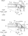
FIG. 7 is a diagram showing a state in which the cartridge is fixed to a loading portion of the stapler main body according to the present embodiment. -
FIG. 8 is an operation diagram of the electric stapler when a lever according to the present embodiment is rotated in a first direction to remove the cartridge from the stapler main body. -
FIG. 9 is an operation diagram of the electric stapler when the lever according to the present embodiment is rotated in a second direction to remove the cartridge from the stapler main body. -
FIG. 10 is an operation diagram of the electric stapler when the cartridge is removed from the stapler main body by pulling the lever according to the present embodiment in a third direction. - Hereinafter, a preferred embodiment of the present disclosure will be described in detail with reference to the accompanying drawings.
- An
electric stapler 1 according to the present embodiment is mounted, for example, in an image forming apparatus that forms a predetermined image on a sheet or in a post-processing apparatus connected to a downstream side of the image forming apparatus in a sheet transport direction. Theelectric stapler 1 performs a binding process on a sheet bundle including a plurality of sheets on which predetermined images are formed by the image forming apparatus using a staple. Specifically, theelectric stapler 1 performs the binding process on the sheet bundle by sequentially performing a clamping step of clamping the sheet bundle, a penetrating step of penetrating a staple through the clamped sheet bundle, and a clinching step of folding leg portions of the staple penetrating the sheet bundle. - As shown in
FIGS. 1 and2 , theelectric stapler 1 includes acartridge 20 in which a staple is accommodated, a staplermain body 10 to which thecartridge 20 is detachably attached, and alever 60 which is provided to the staplermain body 10 so as to be displaceable with respect to the staplermain body 10. Further, theelectric stapler 1 includes adriver mechanism 30 that drives a staple toward a sheet bundle, a table 40 that can move up and down with respect to thedriver mechanism 30, and aclincher portion 50 that folds leg portions of the staple driven by thedriver mechanism 30 and passing through the sheets. - In the present embodiment, a side on which the
driver mechanism 30 is provided is a front side of theelectric stapler 1, and a side on which thelever 60 is provided is a rear side of theelectric stapler 1. A side on which the table 40 and theclincher portion 50 are provided is referred to as an upper side of theelectric stapler 1, and an opposite side is referred to as a lower side. In the present embodiment, a first direction D1, which is a displacement direction of thelever 60, is a gravity direction when theelectric stapler 1 is placed on a floor surface, and corresponds to a lower side with respect to thecartridge 20. A second direction D2, which is a displacement direction of thelever 60, is a direction opposite to the gravity direction and corresponds to an upper side with respect to thecartridge 20. A third direction D3, which is a displacement direction of thelever 60, is a direction opposite to a loading direction D4 when a direction orthogonal to the first direction D1 is defined as the loading direction D4 of thecartridge 20 into the staplermain body 10, and corresponds to a rear side of theelectric stapler 1. - A placement table 70 on which a sheet bundle is placed is provided at a position where the placement table 70 is above the
driver mechanism 30 of the staplermain body 10 and faces the table 40. Thedriver mechanism 30 is disposed on the front side in the staplermain body 10, and is configured to be movable up and down with respect to the placement table 70 based on driving of adrive mechanism 32. Thedriver mechanism 30 forms a staple into a substantially U-shape by folding both ends of the staple by a forming plate (not shown), and drives the staple formed into the substantially U-shape toward the sheet bundle. - The table 40 is disposed to face upper sides of the
driver mechanism 30 and the placement table 70. The table 40 is connected to thedrive mechanism 32 via aframe 12, and is configured to be movable in an approaching direction and a separating direction with respect to the placement table 70 based on the driving of thedrive mechanism 32. A surface (portion) of the table 40 facing the placement table 70 functions as aclamp portion 80 that clamps the sheet bundle between the surface and the placement table 70. The table 40 and theclamp portion 80 are configured to be movable between a clamping position where the sheet bundle is clamped and a home position where the sheet bundle is not clamped. - The
clincher portion 50 is disposed at a front end portion of the table 40 at a position facing thedriver mechanism 30. In cooperation with thedriver mechanism 30, theclincher portion 50 presses the leg portions of the staple penetrating the sheet bundle and folds the legs portion of the staple inward, thereby binding the sheet bundle by the staple. - The
cartridge 20 is detachably attached to aloading portion 110 provided at a rear portion of the staplermain body 10 by being slid from the rear side. Arefill 300 on which sheet-type connected staples are stacked is accommodated in thecartridge 20. Therefill 300 is configured to be mounted in thecartridge 20 by being slid from the rear side of thecartridge 20. The connected staples in therefill 300 are transported to a forming position by a feed mechanism (not shown) of thedriver mechanism 30. - Next, the stapler
main body 10 will be described in detail. - As shown in
FIG. 3 , the staplermain body 10 includes theloading portion 110 into which thecartridge 20 is loaded, and engagementportions 120 that engage and fixes thecartridges 20 loaded in theloading portion 110 into theloading portion 110. - As shown in
FIG. 3 , theloading portion 110 is provided in an upper portion of the staplermain body 10 and has a space portion having a size capable of accommodating thecartridge 20. An insertion and removal opening 112 through which thecartridge 20 can be inserted into and removed from the space portion of theloading portion 110 is formed in a rear wall of the staplermain body 10. In the present embodiment, thecartridge 20 can be loaded into theloading portion 110 from the rear side of the staplermain body 10 through the insertion andremoval opening 112. - As shown in
FIGS. 3 and4 , theengagement portions 120 are formed at two positions on one end side and the other end side in a left-right direction of an upper portion of theloading portion 110, and are disposed at positions facing moving portions 603 (to be described later) of thecartridge 20 loaded in theloading portion 110. As shown inFIG. 4 , theengagement portion 120 includes astep portion 121 and aninclined surface 122 inclined obliquely downward from an upper end of thestep portion 121 toward the rear side. Thestep portion 121 has aflat surface 121a and a substantiallyvertical surface 121b standing from theflat surface 121a. A height of thevertical surface 121b of thestep portion 121 is preferably at least equal to or greater than a radius of a fixingshaft 220 in order to prevent the fixingshaft 220, which will be described later, from coming off rearward from theengagement portion 120. Accordingly, when thecartridge 20 is loaded into the staplermain body 10, the fixingshaft 220 of thecartridge 20 is caught (engaged) by thestep portion 121, so that a rearward movement of the fixingshaft 220 is restricted, and thecartridge 20 can be locked to the staplermain body 10. - Next, the
cartridge 20 will be described in detail. - As shown in
FIGS. 5 and6 , thecartridge 20 includes a cartridgemain body 200, arefill accommodating portion 210 that accommodates a refill, thelever 60 that is attached to the cartridgemain body 200 so as to be displaceable with respect to the cartridgemain body 200, the fixingshaft 220 for fixing thecartridge 20 to the staplermain body 10 when thecartridge 20 is loaded into the staplermain body 10, atorsion coil spring 250 that urges the fixingshaft 220 to a position where the fixingshaft 220 is engaged with and fixed to theengagement portion 120, and adischarge portion 260 that discharges a staple. - As shown in
Figs. 3 and5 , therefill accommodating portion 210 is provided inside the cartridgemain body 200 and includes a space portion having a size capable of accommodating therefill 300. An insertion and removal opening 212 (seeFIG. 3 ) through which therefill 300 can be inserted into and pulled out from the space portion of therefill accommodating portion 210 is formed in a rear wall of the cartridgemain body 200. In the present embodiment, therefill 300 can be loaded into therefill accommodating portion 210 from the rear side of the cartridgemain body 200 through the insertion andremoval opening 212. - Here, the
refill 300 is formed by a box body capable of accommodating the connected staples to which linear staples are connected. A large number of connected staples are stacked in therefill 300. Therefill 300 includes alid member 310 for pressing the uppermost connected staple among the stacked connected staples. Thelid member 310 is configured to be movable up and down in therefill 300 by increasing or decreasing the number of connected staples in therefill 300. - The fixing
shaft 220 is an example of a protruding portion and a fixing portion, and is disposed above therefill accommodating portion 210 and at a rear portion of the cartridgemain body 200 as shown inFIGS. 5 and6 . The protruding portion in the present embodiment is a round bar, but is not limited thereto. The protruding portion may be a triangular protrusion or a quadrangular protrusion. The fixingshaft 220 is disposed such that a longitudinal direction thereof extends along the left-right direction of the cartridgemain body 200. Thetorsion coil spring 250 is attached to a substantially central portion of the fixingshaft 220. A left end side (one end portion) of the fixingshaft 220 is inserted into a vertically long hole (hereinafter, referred to as a long hole) provided in a left side wall connected to anupper wall 202 of the cartridgemain body 200. The left end side of the fixingshaft 220 inserted into the long hole is movably inserted into one lever main body 600 (an extendingportion 600a to be described later) constituting thelever 60, and further protrudes outward. A right end side (right end portion) of the fixingshaft 220 is inserted into a vertically long hole provided in a right side wall connected to theupper wall 202 of the cartridgemain body 200. The right end side of the fixingshaft 220 inserted into the long hole is movably inserted into the other lever main body 600 (an extendingportion 600b to be described later) constituting thelever 60, and further protrudes outward. - As shown in
FIG. 5 , thetorsion coil spring 250 includescoil portions 251, fixedarms 252 each extending from one end side of thecoil portion 251 toward a front side of therefill accommodating portion 210, and loadarms 253 each extending from the other end side of thecoil portion 251 toward the front side of therefill accommodating portion 210. Thetorsion coil spring 250 is an example of an elastic member. Although the torsion coil spring is used in the present embodiment, the elastic member may be a plate spring or a rubber member. The fixedarm 252 is located above theload arm 253. In the present embodiment, thetorsion coil spring 250 having the twocoil portions 251 is used, the fixingshaft 220 is disposed to penetrate thecoil portions 251, and theload arms 253 are configured to be substantially in a center in a cartridge left-right direction. The configuration of thetorsion coil spring 250 is not limited to the configuration of the present embodiment. - A distal end side of the fixed
arm 252 is in contact with the upper wall 202 (seeFIG. 2 and the like) of the cartridgemain body 200. The fixedarm 252 is elastically deformable with a contact point as a fulcrum, and urges the fixingshaft 220 downward on therefill accommodating portion 210 side. Accordingly, as shown inFIG. 4 , both end sides of the fixingshaft 220 abut on opening edges of the movingportions 603 of the levermain body 600, and are disposed at positions where the fixingshaft 220 is engageable with theengagement portions 120. - As described above, in the present embodiment, when the fixing
shaft 220 is fixed by theengagement portion 120 of the cartridgemain body 200, the fixingshaft 220 is located at a first position P1 by an urging force of thetorsion coil spring 250. When the fixing of the fixingshaft 220 to theengagement portion 120 of the cartridgemain body 200 is released, the fixingshaft 220 is located at a second position P2 against an elastic force of thetorsion coil spring 250 as shown inFIG. 8 . The first position P1 is located below the second position P2. After the lock by theengagement portion 120 is released, the fixingshaft 220 moves from the second position to the first position. - As shown in
FIG. 5 , theload arm 253 of thetorsion coil spring 250 is provided so as to be abuttable on the upper surface of thelid member 310 of therefill 300 loaded in therefill accommodating portion 210, and urges thelid member 310 downward, which is a bottom wall side of therefill 300. Accordingly, when therefill 300 is loaded into therefill accommodating portion 210, thelid member 310 of therefill 300 is pressed by theload arm 253 of thetorsion coil spring 250, and the connected staples accommodated in therefill 300 can be held in a stable posture. As described above, in the present embodiment, thetorsion coil spring 250 that elastically supports the fixingshaft 220 also serves as an elastic member that presses thelid member 310 of therefill 300. That is, thecoil portion 251 of thetorsion coil spring 250 functions as an elastic member that abuts against the fixingshaft 220 and urges the fixingshaft 220 to the first position P1, and theload arm 253 functions as an elastic member that urges thelid member 310 of therefill 300 to the bottom wall side of therefill 300. - The
discharge portion 260 is disposed in a front portion of the cartridgemain body 200. Thedischarge portion 260 folds a staple located at a leading end portion of the connected staples fed out from therefill 300 in a substantially U-shape in cooperation with thedriver mechanism 30, and discharges the staple toward the sheet bundle on the placement table 70. - Next, the
lever 60 will be described in detail. - As shown in
FIGS. 4 ,5 , and6 , thelever 60 is attached above therefill accommodating portion 210 and at the rear portion of thecartridge 20 so as to be displaceable with respect to the staplermain body 10. In the present embodiment, thelever 60 is attached to the cartridgemain body 200. When thecartridge 20 is loaded to the staplermain body 10, thelever 60 is displaceable relative to the staplermain body 10. Thelever 60 does not necessarily need to be attached to the cartridge, and may be provided on the staplermain body 10. Thelever 60 includes a levermain body 600 havingdistal end portions 601,proximal end portions 602, and the movingportions 603 provided between thedistal end portions 601 and theproximal end portions 602, and aknob 610 protruding rearward (in the third direction D3) from theproximal end portion 602. - The lever
main body 600 is configured in a substantially U-shape in which a front side of the staplermain body 10 is opened. Left ends and the right ends of the fixingshaft 220 penetrate the levermain body 600. The extendingportions engagement portions main body 10 when thecartridge 20 is loaded into the staplermain body 10. - The moving
portion 603 supports the fixingshaft 220 such that the fixingshaft 220 is movable from the first position P1 to the second position P2 when thelever 60 is displaced downward in the first direction D1 with respect to the stapler main body 10 (seeFIG. 8 ), when thelever 60 is displaced upward in the second direction D2 with respect to the stapler main body 10 (seeFIG. 9 ), or when thelever 60 is displaced rearward in the third direction D3 with respect to the stapler main body 10 (seeFIG. 10 ). In the present embodiment, the movingportion 603 includes an opening portion. A left end portion (one end portion) of the fixingshaft 220 is movably supported by the movingportion 603 of theleft extending portion 600a. The right end portion (the other end portion) of the fixingshaft 220 is movably supported by the moving portion of theright extending portion 600b. The movingportion 603 has, for example, a substantially triangular shape, and has aninclined surface 603a inclined obliquely upward from theproximal end portion 602 toward thedistal end portion 601. In the movingportion 603, acorner portion 603b supporting the fixingshaft 220 at the first position P1 is curved along an arc shape of the fixingshaft 220. - As shown in
FIG. 5 and the like, theknob 610 is a portion to be gripped by a user when thecartridge 20 is removed from the staplermain body 10. Theknob 610 has a substantially U-shape in a plan view, and both end portions thereof are attached to the rear end sides of the levermain body 600. A gap S into which fingers can be inserted is provided between theknob 610 and the cartridgemain body 200 so that the user can easily grip theknob 610. In the present embodiment, theknob 610 is disposed above therefill accommodating portion 210 and at a rear portion of thecartridge 20, so that an amount of protrusion from the rear wall of the staplermain body 10 is prevented. The user grips theknob 610 and rotates or slides theentire lever 60 in any one of the first direction D1, the second direction D2, and the third direction D3, thereby removing thecartridge 20 from the staplermain body 10. - Next, a description will be given of a case where the user mounts the
cartridge 20 on the staplermain body 10. - When the user moves the cartridge
main body 200 to the front side in the direction D4 opposite to the third direction D3 and inserts the cartridgemain body 200 into theloading portion 110 of the staplermain body 10, thecartridge 20 moves forward while sliding on a bottom wall of theloading portion 110 of the stapler main body 10 (seeFIG. 3 ). When thecartridge 20 moves forward, the fixingshaft 220 of the cartridgemain body 200 moves upward against the elastic force of the fixedarm 252 of thetorsion coil spring 250 while sliding on theinclined surface 122 of theengagement portion 120 of the staplermain body 10. - When the
cartridge 20 further moves forward, the fixingshaft 220 climbs over theinclined surface 122 to thestep portion 121 side, and as shown inFIG. 7 , the fixingshaft 220 is urged downward by a restoring force of the fixedarm 252 of thetorsion coil spring 250 to move to the first position P1. As a result, the fixingshaft 220 is engaged with thestep portion 121 of theengagement portion 120, and thecartridge 20 is locked to the staplermain body 10. - Next, a description will be given of a case where the
lever 60 is rotated in the first direction D1 to remove thecartridge 20 from the staplermain body 10.FIG. 8 is a diagram showing an example of an operation of theelectric stapler 1 when thelever 60 is rotated in the first direction D1 to remove thecartridge 20 from the staplermain body 10. - As shown in
FIG. 8 , when theknob 610 of thelever 60 is rotated downward in the first direction D1 by the user in a state where theknob 610 is gripped, theknob 610 side rotates downward (clockwise) about a first fulcrum F1 with respect to the cartridgemain body 200. Here, the first fulcrum F1 is a point where a proximal end side of a lower surface of the lever main body 600 (the extendingportion 600a) and the upper surface of the cartridgemain body 200 are in contact with each other, and is located behind the movingportion 603. Accordingly, the levermain body 600 side of thelever 60 moves upward, and the fixingshaft 220 supported by the movingportion 603 of the levermain body 600 is pushed up against the elastic force of thetorsion coil spring 250. As a result, the fixingshaft 220 is moved to the second position P2 higher than thestep portion 121 of theengagement portion 120, and the fixingshaft 220 is disengaged from theengagement portion 120 of the staplermain body 10. - In this state, when the
knob 610 is pulled rearward in the third direction D3, thecartridge 20 moves rearward, and the fixingshaft 220 climbs over thestep portion 121 of theengagement portion 120 and descends while sliding on theinclined surface 122. The fixingshaft 220 gradually moves downward by the restoring force of thetorsion coil spring 250, and returns to the first position P1 when passing through theinclined surface 122. When thecartridge 20 is further pulled rearward, thecartridge 20 is removed from theloading portion 110 of the staplermain body 10. - Next, a description will be given of a case where the
lever 60 is rotated in the second direction D2 to remove thecartridge 20 from the staplermain body 10.FIG. 9 is a diagram showing an example of an operation of theelectric stapler 1 when thelever 60 is rotated in the second direction D2 to remove thecartridge 20 from the staplermain body 10. - As shown in
FIG. 9 , when thelever 60 is rotated upward in the second direction D2 by the user in a state where thelever 60 is gripped, thelever 60 rotates upward (counterclockwise) about a second fulcrum F2 with respect to the cartridgemain body 200. Here, the second fulcrum F2 is a point where a distal end side of the lower surface of the lever main body 600 (the extendingportion 600a) and the upper surface of the cartridgemain body 200 are in contact with each other, and is located in front of the movingportion 603. - Accordingly, the fixing
shaft 220 supported by the movingportion 603 of thelever 60 is pushed up against the elastic force of thetorsion coil spring 250, and the fixingshaft 220 moves to the second position P2 higher than thestep portion 121 of theengagement portion 120. As a result, the fixingshaft 220 is disengaged from theengagement portion 120 of the staplermain body 10. - In this state, when the
cartridge 20 is pulled rearward in the third direction D3, thecartridge 20 moves rearward, and the fixingshaft 220 climbs over thestep portion 121 of theengagement portion 120 and moves downward while sliding on theinclined surface 122. The fixingshaft 220 gradually moves downward by the restoring force of thetorsion coil spring 250, and returns to the first position P1 when passing through theinclined surface 122. When thecartridge 20 is further pulled rearward, thecartridge 20 is removed from theloading portion 110 of the staplermain body 10. - Next, a description will be given of a case where the
lever 60 is pulled in the third direction D3 to remove thecartridge 20 from the staplermain body 10.FIG. 10 is a diagram showing an example of an operation of theelectric stapler 1 when thelever 60 is pulled in the third direction D3 to remove thecartridge 20 from the staplermain body 10. - As shown in
FIG. 10 , when the user pulls thelever 60 rearward in the third direction D3 in a state where theknob 610 of thelever 60 is gripped, thelever 60 moves rearward with respect to the cartridgemain body 200. That is, the movingportion 603 of thelever 60 moves relative to the fixingshaft 220 of the cartridgemain body 200. Accordingly, the fixingshaft 220 supported by the movingportion 603 of the levermain body 600 rises while sliding on theinclined surface 603a of the movingportion 603 against the elastic force of thetorsion coil spring 250. As a result, the fixingshaft 220 moves to the second position P2 higher than thestep portion 121 of theengagement portion 120, and the fixingshaft 220 is disengaged from theengagement portion 120 of the staplermain body 10. - In this state, when the
lever 60 is further pulled rearward in the third direction D3, theentire cartridge 20 moves rearward, and the fixingshaft 220 climbs over thestep portion 121 of theengagement portion 120 and moves downward while sliding on theinclined surface 122. The fixingshaft 220 gradually moves downward on theinclined surface 122 by the restoring force of thetorsion coil spring 250, and returns to the first position P1 when passing through theinclined surface 122. When thecartridge 20 is further pulled rearward, thecartridge 20 is removed from theloading portion 110 of the staplermain body 10. - As described above, according to the present embodiment, when the
cartridge 20 is removed from the staplermain body 10, one of the three types of operations of thelever 60 in the first direction, the second direction, and the third direction can be selected. As described above, by realizing various operability, it is possible to prevent erroneous operation when the user removes thecartridge 20, to reliably remove thecartridge 20 from the staplermain body 10, and to prevent damage to theelectric stapler 1. - According to the present embodiment, since the
knob 610 of thelever 60 is disposed substantially above therefill accommodating portion 210 and at the rear portion of thecartridge 20, the mount of protrusion from the rear wall of the staplermain body 10 is prevented. Accordingly, theelectric stapler 1 can be downsized as compared with a configuration of the related art in which theknob 610 protrudes outward from the rear wall of the staplermain body 10. - According to the present embodiment, since the
torsion coil spring 250 provided in thecartridge 20 has both the function of urging the fixingshaft 220 to the first position P1 and the function of pressing thelid member 310 of therefill 300, it is possible to reduce the number of components as compared with the case where the elastic member is used for each of the fixingshaft 220 and thelid member 310. Accordingly, it is possible to reduce the cost of theelectric stapler 1 including thecartridge 20 compared to the related art. - Although the preferred embodiment of the present disclosure has been described in detail above with reference to the accompanying drawings, the technical scope of the present disclosure is not limited thereto. It is apparent that a person having ordinary knowledge in the technical field of the present disclosure can conceive various changes or modifications within the scope of the technical idea described in the claims, and it is understood that the changes or modifications naturally belong to the technical scope of the present disclosure.
- For example, although an example in which the fixing
shaft 220 and thelever 60 for fixing and releasing thecartridge 20 to and from the staplermain body 10 are provided on thecartridge 20 side has been described in the embodiment described above, the present disclosure is not limited thereto, and the fixingshaft 220 and thelever 60 may be provided on the staplermain body 10 side. Specifically, theelectric stapler 1 may include the staplermain body 10 including theloading portion 110 into which thecartridge 20 is loaded and the fixingshaft 220 that fixes thecartridge 20 loaded into theloading portion 110 to theloading portion 110, and thelever 60 attached to the staplermain body 10 so as to be displaceable with respect to the staplermain body 10. In this case, the fixingshaft 220 has the protruding portion that is located at the first position P1 when thecartridge 20 is fixed to theloading portion 110 and is located at the second position P2 when the fixing of thecartridge 20 is released. Thelever 60 includes the movingportion 603 that moves the fixingshaft 220 from the first position P1 to the second position P2 when thelever 60 is displaced in the first direction D1, in the second direction D2, and in the third direction D3 with respect to the staplermain body 10.
Claims (11)
- A cartridge (20) to be mounted on a stapler (1), comprising:a cartridge main body (200) configured to accommodate a staple;a lever (60) attached to the cartridge main body (200) to be displaceable with respect to the cartridge main body (200); anda fixing portion (220) for fixing the cartridge (20) to the stapler (1) when the cartridge (20) is loaded on the stapler (1), whereinthe fixing portion (220) is located at a first position (P1) in a fixed state where the cartridge (20) is fixed to the stapler (1), and is located at a second position (P2) in a released state where the fixed state is released,the lever (60) has a moving portion (603) that moves the fixing portion (220) to the second position (P2) when the lever (60) is displaced in a first direction and a second direction with respect to the cartridge main body (200),the fixing portion (220) has a fixing shaft (220) that protrudes outward from the moving portion (603),the fixing shaft (220) abuts against the moving portion (603) until the fixing shaft (220) is displaced from the first position (P1) the second position (P2),the moving portion (603) includes a through hole that has an inclined surface (603a) inclined obliquely in an upper-lower direction and a corner portion (603b) that supports the fixing shaft (220) at the first position (P1), andthe fixing shaft (220) is inserted in the through hole.
- The cartridge (20) according to claim 1, whereinthe first direction is downward with respect to the cartridge main body (200), andthe second direction is upward with respect to the cartridge main body (200).
- The cartridge (20) according to claim 2, wherein
the moving portion (603) moves the fixing shaft (220) to the second position (P2) when the lever (60) is displaced in a third direction with respect to the cartridge main body (200). - The cartridge (20) according to claim 3, whereina loading direction in which the cartridge (20) is loaded into the stapler (1) is a direction intersecting the first direction, andthe third direction is a direction opposite to the loading direction.
- The cartridge (20) according to claim 3, whereinthe lever (60) includes a lever main body (600) having a proximal end portion (602), a distal end portion (601), the moving portion (603) between the proximal end portion (602) and the distal end portion (601), and a knob (610) protruding from the proximal end portion (602) in the third direction,the moving portion (603) has an inclined surface (603a) inclined in the second direction from the proximal end portion (602) toward the distal end portion (601), andthe fixing shaft (220) abuts against the inclined surface (603a) and moves in the second direction along the inclined surface (603a) when the lever (60) is displaced in the third direction.
- The cartridge (20) according to claim 4, whereinthe first position (P1) is located in the first direction with respect to the second position (P2), andthe moving portion (603) moves the fixing shaft (220) in the second direction when the lever (60) is displaced in the first direction, the second direction, and the third direction with respect to the stapler (1).
- The cartridge (20) according to claim 4, whereinthe lever (60) includes a lever main body (600) having a proximal end portion (602), a distal end portion (601), the moving portion (603) between the proximal end portion (602) and the distal end portion (601), and a knob (610) protruding from the proximal end portion (602) in the third direction,the lever main body (600) has a first fulcrum portion closer to the proximal end portion (602) side than the moving portion (603),the knob (610) is rotatable in the first direction around the first fulcrum portion as a fulcrum, andthe moving portion (603) moves in the second direction as the knob (610) rotates in the first direction.
- The cartridge (20) according to claim 4, whereinthe lever (60) includes a lever main body (600) having a proximal end portion (602), a distal end portion (601), the moving portion (603) between the proximal end portion (602) and the distal end portion (601), and a knob (610) protruding from the proximal end portion (602) in the third direction,the lever main body (600) has a second fulcrum portion closer to the distal end portion (601) side than the moving portion (603),the knob (610) is rotatable in the second direction around the second fulcrum portion as a fulcrum, andthe moving portion (603) moves in the second direction as the knob (610) rotates in the second direction.
- The cartridge (20) according to claim 4, wherein
the fixing shaft (220) is located closer to the second direction than the staple accommodated in the cartridge main body (200). - The cartridge (20) according to claim 3, further comprisingan elastic member (250) configured to urge the fixing shaft (220) to the first position (P1), whereinthe elastic member (250) presses the staple accommodated in the cartridge main body (200) in the first direction.
- A stapler (1) comprising:a main body including a loading portion in which a cartridge (20) is loaded and a fixing portion (220) that fixes the cartridge (20) loaded in the loading portion into the loading portion; anda lever (60) attached to the main body to be displaceable with respect to the main body, whereinthe fixing portion (220) has a protruding portion that is located at a first position (P1) in a fixed state where the cartridge (20) is fixed to the loading portion and is located at a second position (P2) in a released state where the fixed state of the cartridge (20) is released, andthe lever (60) has a moving portion (603) that moves the protruding portion from the first position (P1) to the second position (P2) when the lever (60) is displaced in a first direction and a second direction different from the first direction with respect to the main body,the fixing portion (220) has a fixing shaft (220) that protrudes outward from the moving portion (603),the protruding portion of the fixing shaft (220) abuts against the moving portion (603) until the fixing shaft (220) is displaced from the first position (P1) the second position (P2),the moving portion (603) includes a through hole that has an inclined surface (603a) inclined obliquely in an upper-lower direction and a corner portion that supports the protruding portion at the first position (P1), andthe protruding portion is inserted in the through hole.
Applications Claiming Priority (2)
| Application Number | Priority Date | Filing Date | Title |
|---|---|---|---|
| JP2022207984A JP2024092215A (en) | 2022-12-26 | 2022-12-26 | Cartridges and staplers |
| EP23219681.6A EP4393651A1 (en) | 2022-12-26 | 2023-12-22 | Cartridge and stapler |
Related Parent Applications (1)
| Application Number | Title | Priority Date | Filing Date |
|---|---|---|---|
| EP23219681.6A Division EP4393651A1 (en) | 2022-12-26 | 2023-12-22 | Cartridge and stapler |
Publications (2)
| Publication Number | Publication Date |
|---|---|
| EP4530037A2 true EP4530037A2 (en) | 2025-04-02 |
| EP4530037A3 EP4530037A3 (en) | 2025-06-11 |
Family
ID=89321546
Family Applications (2)
| Application Number | Title | Priority Date | Filing Date |
|---|---|---|---|
| EP23219681.6A Pending EP4393651A1 (en) | 2022-12-26 | 2023-12-22 | Cartridge and stapler |
| EP25158362.1A Pending EP4530037A3 (en) | 2022-12-26 | 2023-12-22 | Cartridge and stapler |
Family Applications Before (1)
| Application Number | Title | Priority Date | Filing Date |
|---|---|---|---|
| EP23219681.6A Pending EP4393651A1 (en) | 2022-12-26 | 2023-12-22 | Cartridge and stapler |
Country Status (4)
| Country | Link |
|---|---|
| US (1) | US12496743B2 (en) |
| EP (2) | EP4393651A1 (en) |
| JP (1) | JP2024092215A (en) |
| CN (1) | CN118254492A (en) |
Citations (1)
| Publication number | Priority date | Publication date | Assignee | Title |
|---|---|---|---|---|
| JP2019089322A (en) | 2017-11-10 | 2019-06-13 | マックス株式会社 | Refill |
Family Cites Families (8)
| Publication number | Priority date | Publication date | Assignee | Title |
|---|---|---|---|---|
| US5580066A (en) * | 1994-04-07 | 1996-12-03 | Acco Usa, Inc. | Cartridge stapler with jam resistant mechanism |
| JP3328920B2 (en) * | 1995-10-02 | 2002-09-30 | マックス株式会社 | Staple cartridge attachment / detachment mechanism for electric stapler |
| DE29603812U1 (en) * | 1996-03-01 | 1996-06-13 | Prebena Wilfried Bornemann, 63679 Schotten | Device with a magazine |
| JP3598767B2 (en) * | 1997-09-26 | 2004-12-08 | マックス株式会社 | Cartridge removal mechanism for electric stapler |
| JP4029830B2 (en) * | 2003-12-04 | 2008-01-09 | マックス株式会社 | Detaching device for cartridge in electric stapler |
| JP4438545B2 (en) * | 2004-07-15 | 2010-03-24 | マックス株式会社 | Staple cartridge attachment / detachment mechanism in stapler |
| EP3549735B1 (en) * | 2017-11-10 | 2020-09-23 | Max Co., Ltd. | Refill |
| US11524397B2 (en) * | 2020-02-05 | 2022-12-13 | Worklife Brands Llc | Stapler with moveable strike plate and integrated accessibility features |
-
2022
- 2022-12-26 JP JP2022207984A patent/JP2024092215A/en active Pending
-
2023
- 2023-12-22 EP EP23219681.6A patent/EP4393651A1/en active Pending
- 2023-12-22 CN CN202311776595.5A patent/CN118254492A/en active Pending
- 2023-12-22 EP EP25158362.1A patent/EP4530037A3/en active Pending
- 2023-12-26 US US18/396,381 patent/US12496743B2/en active Active
Patent Citations (1)
| Publication number | Priority date | Publication date | Assignee | Title |
|---|---|---|---|---|
| JP2019089322A (en) | 2017-11-10 | 2019-06-13 | マックス株式会社 | Refill |
Also Published As
| Publication number | Publication date |
|---|---|
| US12496743B2 (en) | 2025-12-16 |
| EP4393651A1 (en) | 2024-07-03 |
| JP2024092215A (en) | 2024-07-08 |
| CN118254492A (en) | 2024-06-28 |
| EP4530037A3 (en) | 2025-06-11 |
| US20240208104A1 (en) | 2024-06-27 |
Similar Documents
| Publication | Publication Date | Title |
|---|---|---|
| US8033437B2 (en) | Staple refill, stapler, and cartridge | |
| US10906201B2 (en) | Staple-refill | |
| JP7058441B2 (en) | Staple remover and peripherals or image forming equipment | |
| TWI583513B (en) | Paper handling device | |
| KR100777471B1 (en) | Staple Cartridge in Electric Stapler | |
| CN1635941A (en) | Jam clearing mechanism for a stapler | |
| EP4393651A1 (en) | Cartridge and stapler | |
| US20140231487A1 (en) | Stapler | |
| CN100415468C (en) | stapler | |
| SE517108C2 (en) | Stapler | |
| JP2004058187A (en) | Cartridge for stapler | |
| US9085088B2 (en) | Stapler | |
| JP6908815B2 (en) | Staple remover | |
| CN1585689A (en) | Staple cartridge | |
| CN118254132A (en) | stapler | |
| JP2009262283A (en) | Staple feeding mechanism of stapler | |
| WO2002018111A2 (en) | Stapler device | |
| TW200300402A (en) | Staple pack | |
| JP4413159B2 (en) | Paper post-processing device | |
| JP4085787B2 (en) | Stapler staple cartridge | |
| JP2005035151A (en) | Staple supply mechanism of electromotive stapler | |
| JP3489352B2 (en) | Clamping device | |
| CN100522498C (en) | Stapler | |
| JP2005014416A (en) | Staple feeding mechanism of electric stapler |
Legal Events
| Date | Code | Title | Description |
|---|---|---|---|
| PUAI | Public reference made under article 153(3) epc to a published international application that has entered the european phase |
Free format text: ORIGINAL CODE: 0009012 |
|
| STAA | Information on the status of an ep patent application or granted ep patent |
Free format text: STATUS: REQUEST FOR EXAMINATION WAS MADE |
|
| 17P | Request for examination filed |
Effective date: 20250217 |
|
| AC | Divisional application: reference to earlier application |
Ref document number: 4393651 Country of ref document: EP Kind code of ref document: P |
|
| AK | Designated contracting states |
Kind code of ref document: A2 Designated state(s): AL AT BE BG CH CY CZ DE DK EE ES FI FR GB GR HR HU IE IS IT LI LT LU LV MC ME MK MT NL NO PL PT RO RS SE SI SK SM TR |
|
| REG | Reference to a national code |
Ref country code: DE Ref legal event code: R079 Free format text: PREVIOUS MAIN CLASS: B27F0007380000 Ipc: B25C0005160000 |
|
| PUAL | Search report despatched |
Free format text: ORIGINAL CODE: 0009013 |
|
| AK | Designated contracting states |
Kind code of ref document: A3 Designated state(s): AL AT BE BG CH CY CZ DE DK EE ES FI FR GB GR HR HU IE IS IT LI LT LU LV MC ME MK MT NL NO PL PT RO RS SE SI SK SM TR |
|
| RIC1 | Information provided on ipc code assigned before grant |
Ipc: B27F 7/38 20060101ALI20250506BHEP Ipc: B25C 5/16 20060101AFI20250506BHEP |