EP4530035A1 - Removal device and print system - Google Patents
Removal device and print system Download PDFInfo
- Publication number
- EP4530035A1 EP4530035A1 EP24192610.4A EP24192610A EP4530035A1 EP 4530035 A1 EP4530035 A1 EP 4530035A1 EP 24192610 A EP24192610 A EP 24192610A EP 4530035 A1 EP4530035 A1 EP 4530035A1
- Authority
- EP
- European Patent Office
- Prior art keywords
- section
- platen
- joint
- support portion
- removal device
- Prior art date
- Legal status (The legal status is an assumption and is not a legal conclusion. Google has not performed a legal analysis and makes no representation as to the accuracy of the status listed.)
- Pending
Links
Images





Classifications
-
- B—PERFORMING OPERATIONS; TRANSPORTING
- B41—PRINTING; LINING MACHINES; TYPEWRITERS; STAMPS
- B41J—TYPEWRITERS; SELECTIVE PRINTING MECHANISMS, i.e. MECHANISMS PRINTING OTHERWISE THAN FROM A FORME; CORRECTION OF TYPOGRAPHICAL ERRORS
- B41J3/00—Typewriters or selective printing or marking mechanisms characterised by the purpose for which they are constructed
- B41J3/407—Typewriters or selective printing or marking mechanisms characterised by the purpose for which they are constructed for marking on special material
- B41J3/4078—Printing on textile
-
- D—TEXTILES; PAPER
- D06—TREATMENT OF TEXTILES OR THE LIKE; LAUNDERING; FLEXIBLE MATERIALS NOT OTHERWISE PROVIDED FOR
- D06P—DYEING OR PRINTING TEXTILES; DYEING LEATHER, FURS OR SOLID MACROMOLECULAR SUBSTANCES IN ANY FORM
- D06P5/00—Other features in dyeing or printing textiles, or dyeing leather, furs, or solid macromolecular substances in any form
- D06P5/003—Transfer printing
-
- B—PERFORMING OPERATIONS; TRANSPORTING
- B25—HAND TOOLS; PORTABLE POWER-DRIVEN TOOLS; MANIPULATORS
- B25J—MANIPULATORS; CHAMBERS PROVIDED WITH MANIPULATION DEVICES
- B25J11/00—Manipulators not otherwise provided for
-
- B—PERFORMING OPERATIONS; TRANSPORTING
- B25—HAND TOOLS; PORTABLE POWER-DRIVEN TOOLS; MANIPULATORS
- B25J—MANIPULATORS; CHAMBERS PROVIDED WITH MANIPULATION DEVICES
- B25J15/00—Gripping heads and other end effectors
- B25J15/0019—End effectors other than grippers
-
- B—PERFORMING OPERATIONS; TRANSPORTING
- B41—PRINTING; LINING MACHINES; TYPEWRITERS; STAMPS
- B41J—TYPEWRITERS; SELECTIVE PRINTING MECHANISMS, i.e. MECHANISMS PRINTING OTHERWISE THAN FROM A FORME; CORRECTION OF TYPOGRAPHICAL ERRORS
- B41J11/00—Devices or arrangements of selective printing mechanisms, e.g. ink-jet printers or thermal printers, for supporting or handling copy material in sheet or web form
- B41J11/02—Platens
- B41J11/14—Platen-shift mechanisms; Driving gear therefor
Definitions
- a print system is known that performs printing on a medium, such as a cloth or the like, held by a platen.
- a device is proposed for automatically performing an operation to remove the printed medium from the platen.
- JP 2020-110874 A a technique is disclosed for performing an operation of folding and stacking T-shirts using a robot arm provided on a robot.
- a robot hand of the robot arm normally grips a target object between a plurality of fingers.
- the robot arm may fail to remove the medium from the platen.
- An object of the present invention is to provide a removal device for realizing an operation of removing a medium from a platen even when the excess section is not formed in the medium, and a print system provided with the removal device.
- Various embodiments herein provide a first aspect of a removal device configured to remove a medium from a platen.
- the medium includes a first layer and a second layer.
- the first layer and the second layer connect with each other at one end of the medium and are separate from each other at the other end of the medium.
- the first layer is over a first surface of the platen
- the second layer is under a second surface of the platen
- the one end of the medium is at a front end of the platen
- the other end of the medium is at a back end of the platen, respectively.
- the removal device includes a first support portion and a second support portion. The first support portion is configured to contact one of the first layer and the second layer of the medium.
- the second support portion includes a second contact portion.
- the second contact portion is configured to contact the other of the first layer and the second layer of the medium.
- the second contact portion includes a rotary body.
- the second contact portion is configured to move to the other of the first layer and the second layer of the medium.
- the second contact portion is configured to move in a forward direction in a state that the first support portion contacts the one of the first layer and the second layer of the medium and the rotary body of the second contact portion contacts the other of the first layer and the second layer of the medium.
- the removal device of the first aspect may further include a connecting portion positioned in front of the platen, and connecting the first support portion and the second support portion with each other.
- the second support portion may include a link mechanism.
- the link mechanism may include a first joint and a second j oint. One end of the first joint may be connected to the connecting portion. One end of the second joint may be connected to another end of the first joint.
- the rotary body may be provided at another end of the second joint.
- the removal device may further include a rotary mechanism configured to rotate the first joint with respect to the connecting portion.
- Various embodiments also provide a second aspect of a removal device that removes a medium from a platen.
- the medium includes a first section, a second section, and a third section.
- the first section extends along a first surface being an end surface of the platen in a first direction.
- the second section extends along a second surface being an end surface of the platen in a second direction opposite to the first direction.
- the third section joins the first section and the second section and is folded back at an end portion of the platen in a third direction orthogonal to the first direction and the second direction.
- the removal device includes a first support portion, a second support portion, and a connecting portion. The first support portion is positioned on an opposite side from the platen with respect to the first section of the medium in the first direction.
- the second support portion includes a second contact portion.
- the second contact portion is configured to move in the third direction, and coming into contact with a second opposite surface of the second section of the medium.
- the second opposite surface is on the opposite side to a second facing surface of the second section of the medium.
- the second facing surface faces the second surface of the platen.
- the connecting portion is positioned on the opposite side from the platen with respect to the first support portion and the second support portion in the third direction.
- the connecting portion is configured to connect the first support portion and the second support portion with each other.
- the second contact portion of the second support portion may move in the third direction in a state of contact with the second section of the medium.
- the first support portion may come into contact with a first opposite surface of the first section of the medium.
- the first opposite surface may be on the opposite side to a first facing surface of the first section of the medium.
- the first facing surface may face the first surface of the platen.
- the second contact portion may include a rotary body configured to rotate centered on a rotary shaft orthogonal to the first direction, the second direction, and the third direction.
- the second support portion may include a link mechanism.
- the link mechanism may include a first joint and a second joint. One end of the first joint may be connected to the connecting portion. One end of the second joint may be connected to another end of the first joint.
- the rotary body may be provided at another end of the second joint.
- the removal device may further include a rotary mechanism configured to rotate the first joint with respect to the connecting portion.
- the removal device of the second aspect may further include a spring configured to urge the rotary body toward the platen.
- the rotary body may include a one-way clutch.
- the one-way clutch may be configured to allow the rotary body to rotate in a first rotation direction and not allow the rotary body to rotate in a second rotation direction.
- the first rotation direction may be a rotation direction in which a contact section of the rotary body with the medium moves in the third direction.
- the second rotation direction may be opposite to the first rotation direction.
- the second support portion may include a first shaft.
- the rotary mechanism may include a shaft support member and a movement mechanism.
- the shaft may be configured to support the first shaft.
- the movement mechanism may be configured to move the shaft support member in the first direction and the second direction.
- the second support portion may be configured to rotate around a second shaft separated from the first shaft, as a result of the shaft support member moving in the first direction and the second direction.
- the rotary mechanism may include a first motor.
- the removal device of the second aspect may further include a second motor configured to rotate the second j oint with respect to the first joint.
- the first support portion may include a plate body including a third surface facing the first section of the medium.
- the third surface may be inclined with respect to a direction parallel to the first surface.
- the second contact portion may be made of rubber, and the third surface may be made of rubber.
- the second support portion may include a link mechanism.
- the link mechanism may include a first joint and a second joint. One end of the first joint may be connected to the connecting portion. One end of the second joint may be connected to another end of the first joint.
- the rotary body may be provided at another end of the second joint.
- the removal device may further include a rotary mechanism configured to rotate the first joint with respect to the connecting portion. When the first joint is rotated by the rotary mechanism, a movement trajectory of a connection section between the first joint and the second joint may pass farther to an opposite side of the first section of the medium in the first direction than a virtual plane extending along the third surface of the first support portion.
- the removal device of the first and the second aspect removes the medium from the platen by moving the second contact portion in the third direction in a state of the second section of the medium being caused to be in contact with the second contact portion of the second support portion.
- the removal device contributes to removing the medium from the platen even when an excess section is not formed in the medium.
- Various embodiments also provide a third aspect of a print system that includes a platen and a removal device.
- the removal device removes a medium from a platen.
- the medium includes a first section, a second section, and a third section.
- the first section extends along a first surface being an end surface of the platen in a first direction.
- the second section extends along a second surface being an end surface of the platen in a second direction opposite to the first direction.
- the third section joins the first section and the second section and is folded back at an end portion of the platen in a third direction orthogonal to the first direction and the second direction.
- the removal device includes a first support portion, a second support portion, and a connecting portion.
- the first support portion is positioned on an opposite side from the platen with respect to the first section of the medium in the first direction.
- the second support portion includes a second contact portion.
- the second contact portion is configured to move in the third direction, and coming into contact with a second opposite surface of the second section of the medium.
- the second opposite surface is on the opposite side to a second facing surface of the second section of the medium.
- the second facing surface faces the second surface of the platen.
- the connecting portion is positioned on the opposite side from the platen with respect to the first support portion and the second support portion in the third direction. The connecting portion is configured to connect the first support portion and the second support portion with each other.
- the print system of the third aspect may further include a head configured to print by ejecting ink onto the medium held on the platen.
- the second support portion may include a rotary body configured to rotate centered on a rotary shaft orthogonal to the first direction, the second direction, and the third direction.
- the second support portion may include a link mechanism.
- the link mechanism may include a first joint and a second joint. One end of the first joint may be connected to the connecting portion. One end of the second joint may be connected to another end of the first joint.
- the rotary body may be provided at another end of the second joint.
- the print system may further include a rotary mechanism configured to rotate the first joint with respect to the connecting portion.
- the print system of the third aspect may further include a spring configured to urge the rotary body toward the platen.
- the rotary body may include a one-way clutch.
- the one-way clutch may be configured to allow the rotary body to rotate in a first rotation direction and not allow the rotary body to rotate in a second rotation direction.
- the first rotation direction may be a rotation direction in which a contact section of the rotary body with the medium moves in the third direction.
- the second rotation direction may be opposite to the first rotation direction.
- the first support portion may include a plate body including a third surface facing the first section of the medium.
- the third surface may be inclined with respect to a direction parallel to the first surface.
- the removal device may be configured to move relative to the platen in a direction close to the platen and in a direction away from the platen.
- An embodiment of a print system 1 according to the present invention will be described with reference to the drawings.
- the referenced drawings are used to illustrate technological features that can be adopted by the present invention. Illustrated configurations of devices and the like are not intended to limit the present invention to the embodiment alone, and are simply explanatory examples.
- An upward direction, a downward direction, a lower left direction, an upper right direction, an upper left direction, and a lower right direction in FIG. 2 are, respectively, an upward direction, a downward direction, a front direction, a rear direction, a left direction, and a right direction of a removal device 20 and a platen unit 8.
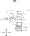
- the print system 1 is provided with the removal device 20, the platen unit 8, and a printer 9.
- the platen unit 8 is conveyed in a state of a cloth T being held on a platen 84.
- a type of the cloth T is not particularly limited. In the present embodiment, the cloth T is a T-shirt.
- the platen unit 8 is conveyed in a conveyance direction Y1.
- the printer 9 is provided at a part of a conveyance path of the platen unit 8.
- the printer 9 is provided with a head 9A that discharges ink.
- the printer 9 performs printing on the cloth T by discharging the ink from the head 9A onto the cloth T held by the platen 84.
- the removal device 20 is positioned downstream of the printer 9 in the conveyance direction Y1, on the conveyance path of the platen unit 8.
- the removal device 20 moves in an approaching direction Y21, which is a direction from a position separated from the conveyance path of the platen unit 8 toward a position close to the conveyance path, and in a separating direction Y22, which is a direction from the position close to the conveyance path of the platen unit 8 toward the position separated from the conveyance path.
- the removal device 20 removes the cloth T, on which the printing by the printer 9 has been performed, from the platen 84.
- the direction of the conveyance direction Y1 of the platen unit 8 coincides with a direction to the left.
- the platen unit 8 is provided with a base 81, a right surface plate 82A, a left surface plate, a rear surface plate 83, and the platen 84.
- the shape of the base 81 is a rectangular shape in a plan view.
- a right support portion 820A and a left support portion 820B are fixed to the upper surface of the base 81.
- the right support portion 820A and the left support portion 820B are separated from each other in the left-right direction.
- the right support portion 820A is positioned to the right of the left support portion 820B.
- the right surface plate 82A has a plate shape and is orthogonal to the left-right direction.
- the right surface plate 82A includes a first extension portion 821 and a second extension portion 822.
- the first extension portion 821 extends upward from a portion of the right support portion 820A further to the rear than a substantial center thereof in the front-rear direction.
- the second extension portion 822 extends to the front from a front end portion of the first extension portion 821 and from a position separated upward from a lower end portion of the first extension portion 821.
- the base 81 and the second extension portion 822 are separated from each other in the up-down direction.
- the left surface plate has the same shape as the right surface plate 82A.
- a first extension portion of the left surface plate extends upward from a portion of the left support portion 820B further to the rear than a substantial center thereof in the front-rear direction.
- a second extension portion of the left surface plate is separated upward from the base 81.
- the right surface plate 82A and the left surface plate are separated from each other in the left-right direction.
- the rear surface plate 83 has a plate shape and extends upward from a rear end portion of the base 81.
- the platen 84 has a plate shape.
- the shape of the platen 84 is a substantially rectangular shape that is long in the front-rear direction.
- the platen 84 includes an upper surface 841 and a lower surface 842.
- the upper surface 841 is an end surface of the platen 84 in the upward direction.
- the lower surface 842 is an end surface of the platen 84 in the downward direction.
- the upper surface 841 and the lower surface 842 extend horizontally, and are orthogonal to the up-down direction. Respective upper end portions of the second extension portion 822 of the right surface plate 82A and the second extension portion of the left surface plate are fixed to the lower surface 842 of the platen 84.
- An end portion at the front of the platen 84 will be referred to as a "front end section 84F".
- An end portion on the right of the platen 84 will be referred to as a “right end section 84R”.
- An end portion on the left of the platen 84 will be referred to as a "left end section 84L”.
- An end portion at the rear of the platen 84 will be referred to as a "rear end section 84S”.
- the front end section 84F, the right end section 84R, the left end section 84L, and the rear end section 84S extend in the up-down direction between the upper surface 841 and the lower surface 842, and join the upper surface 841 with the lower surface 842.
- Each of the front end section 84F, the right end section 84R, and the left end section 84L extend linearly.
- the rear end section 84S extends while curving.
- the cloth T such as the T-shirt or the like, is attached to the platen 84.
- a neck portion of the cloth T is positioned at the front end section 84F of the platen 84.
- the cloth T is in a state in which a section corresponding to the front end section 84F of the platen 84 is folded back.
- a hem section of the cloth T is positioned at the rear end section 84S.
- the cloth T When mounting the cloth T to the platen 84, the cloth T is stretched to the rear, to the left, and to the right such that the cloth T is not slack with respect to the upper surface 841 of the platen 84.
- a section around the neck of the cloth T is closely attached to the front end section 84F of the platen 84.
- a section of the cloth T from the right sleeve to the hem is folded back at the right end section 84R of the platen 84, and is fed between the lower surface 842 of the platen 84 and the second extension portion 822 of the right surface plate 82A.
- a section of the cloth T from the left sleeve to the hem is folded back at the left end section 84L of the platen 84, and is fed between the lower surface 842 of the platen 84 and the second extension portion of the left surface plate.
- the approaching direction Y21 in which the removal device 20 moves from the position separated from the conveyance path of the platen unit 8 toward the position close to the conveyance path coincides with the direction to the rear.
- the separating direction Y22 in which the removal device 20 moves from the position close to the conveyance path of the platen unit 8 toward the position separated from the conveyance path coincides with the direction to the front.
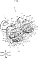
- the removal device 20 is provided with a first support portion 2, a second support portion 3, a connecting portion 4, and a rotating mechanism 5.
- the rotating mechanism 5 includes an end effector 5A connected to a robot arm.
- the robot arm is a vertical articulated robot, and includes links and joints.
- the end effector 5A is attached to a leading end of the robot arm.
- a flat surface portion 50 which is orthogonal to the front-rear direction, is formed at a rear end portion of the end effector 5A.
- the end effector 5A supports a pawl unit 51 that protrudes to the rear from the flat surface portion 50.
- the pawl unit 51 includes a pawl 51A.
- the pawl 51A has a U-shaped groove 51B.
- the connecting portion 4 is connected to the end effector 5A.
- the connecting portion 4 moves in the front-rear direction or the up-down direction in accordance with the robot arm moving the end effector 5A. Further, the connecting portion 4 is provided to the front of the first support portion 2 and the second support portion 3 to be described later, and connects the first support portion 2 and the second support portion 3.
- the connecting portion 4 includes a base portion 41.
- the base portion 41 has a plate shape that is long in the left-right direction, and is orthogonal to the front-rear direction.
- a length in the up-down direction of the base portion 41 is substantially the same as a length of the flat surface portion 50 of the end effector 5A.
- a length in the left-right direction of the base portion 41 is longer than a length in the left-right direction of the flat surface portion 50 of the end effector 5A.
- the base portion 41 is connected to the end effector 5A.
- a central portion in the left-right direction of a front surface of the base portion 41 faces the flat surface portion 50 of the end effector 5A.
- a through hole 50H is provided in the central portion in the left-right direction of the base portion 41.
- the pawl unit 51 extending from the flat surface portion 50 of the end effector 5A is inserted through the through hole 50H, and protrudes further to the rear than a rear surface of the base portion 41.
- An upward extending portion 42A is provided in the vicinity of a right end of the base portion 41.
- An upward extending portion 42B is provided in the vicinity of a left end of the base portion 41.
- Each of the upward extending portions 42A and 42B protrude further upward than an upper end portion of the base portion 41.
- a rearward extending portion 43A is provided in a rear surface of the base portion 41, further to the right than a center thereof in the left-right direction.
- the rearward extending portion 43A extends to the rear.
- the rearward extending portion 43A has a plate shape, and is orthogonal to the left-right direction.
- Abridge portion 45A is provided at a right surface of the rearward extending portion 43A.
- the bridge portion 45A has a rod shape and extends to the right.
- a rearward extending portion 44A is provided at a right end portion of the bridge portion 45A.
- the rearward extending portion 44A extends diagonally upward and to the rear.
- the rearward extending portion 44A has a plate shape and is orthogonal to the left-right direction.
- the rearward extending portions 43A and 44A are separated from each other in the left-right direction.
- a rearward extending portion 43B is provided in the rear surface of the base portion 41, further to the left than the center thereof in the left-right direction.
- the rearward extending portion 43B extends to the rear.
- the rearward extending portion 43B has a plate shape, and is orthogonal to the left-right direction.
- a bridge portion 45B is provided at a left surface of the rearward extending portion 43B.
- the bridge portion 45B has a rod shape and extends to the left.
- a rearward extending portion 44B is provided at a left end portion of the bridge portion 45B.
- the rearward extending portion 44B extends diagonally upward and to the rear.
- the rearward extending portion 44B has a plate shape and is orthogonal to the left-right direction.
- the rearward extending portions 43B and 44B are separated from each other in the left-right direction.
- a through hole that extends in the left-right direction is provided in each of rear end portion of each of the rearward extending portions 43A, 43B, 44A, and 44B.
- the through holes of each of the rearward extending portions 43A, 43B, 44A, and 44B are aligned on a straight line in the left-right direction.
- the first support portion 2 is in contact with the cloth T attached to the platen 84 from above, and supports the cloth T.
- the first support portion 2 includes a first right support portion 2A and a first left support portion 2B.
- the first right support portion 2A and the first left support portion 2B have the same shape.
- the first right support portion 2A includes an extension portion 21A and a plate body 22A.
- the extension portion 21A has a plate shape and is orthogonal to the up-down direction.
- the extension portion 21A extends toward the rear from an upper end portion of the upward extending portion 42A of the connecting portion 4.
- the plate body 22A is connected to a rear end portion of the extension portion 21A.
- the plate body 22A includes a base plate 23A and a rubber plate 24A.
- the base plate 23A is made of metal, and the rubber plate 24A is made of rubber.
- the rubber plate 24A is bonded to a lower surface of the base plate 23A.
- the plate body 22A extends diagonally upward and to the rear from a connection portion with the extension portion 21A.
- the rubber plate 24A is exposed to a lower surface 220A of the plate body 22A.
- the lower surface 220A is inclined with respect to the horizontal direction.
- a direction orthogonal to the lower surface 220A and oriented in the opposite direction to the base plate 23A is oriented diagonally to the rear and downward.
- the first left support portion 2B includes an extension portion 21B and a plate body 22B.
- the extension portion 21B extends toward the rear from an upper end portion of the upward extending portion 42B of the connecting portion 4.
- the plate body 22B includes a base plate 23B and a rubber plate 24B.
- the extension portion 21B, the plate body 22B, the base plate 23B, and the rubber plate 24B correspond to the extension portion 21A, the plate body 22A, the base plate 23A, and the rubber plate 24A of the first right support portion 2A.
- a lower surface 220B of the plate body 22B corresponds to the lower surface 220A of the plate body 22A.
- the second support portion 3 is in contact with the cloth T attached to the platen 84 from below, and supports the cloth T.
- the second support portion 3 includes a second right support portion 3A, a second left support portion 3B, and a bridge portion 3C.
- the second right support portion 3A and the second left support portion 3B have the same shape.
- the bridge portion 3C spans between the second right support portion 3A and the second left support portion 3B.
- the second right support portion 3A includes a link mechanism 6A.
- the link mechanism 6A includes a first joint 61 and a second joint 62.
- the first joint 61 includes plate-shaped support bodies 61A and 61B having a substantial L shape in a right side view.
- the support bodies 61A and 61B have the same shape.
- the support bodies 61A and 61B are orthogonal to the left-right direction.
- the support body 61A is positioned to the left of the rearward extending portion 44A of the connecting portion 4.
- the support body 61B is positioned to the right of the rearward extending portion 43A of the connecting portion 4.
- the support body 61A includes extending portions 601 and 602 extending from a section at the left of the rearward extending portion 44A of the connecting portion 4. Directions in which the respective extending portions 601 and 602 extend are orthogonal to each other.
- the extending portions 601 and 602 of the support body 61B extend from a section at the right of the rearward extending portion 43A of the connecting portion 4.
- through holes are formed at sections at which the extending portions 601 and 602 intersect.
- a rotary shaft 46 has a circular column shape, and extends in the left-right direction.
- the rotary shaft 46 is inserted through the through holes of each of the rearward extending portions 43A, 43B, 44A, and 44B of the connecting portion 4, and through the through holes of each of the support bodies 61A and 61B.
- the first joint 61 is supported so as to be rotatable around the connecting portion 4 centered on the rotary shaft 46.
- the first joint 61 further includes a bridge body 61C and a rotary shaft 63.
- the bridge body 61C is provided between leading end portions of the extending portions 602 of each of the support bodies 61A and 61B.
- a through hole is provided in the bridge body 61C.
- the rotary shaft 63 has a circular column shape, and extends in the left-right direction.
- the rotary shaft 63 is inserted through through holes provided in leading end portions of the extending portions 601 of each of the support bodies 61A and 61B.
- a right end portion of the rotary shaft 63 protrudes further to the right than the support body 61A.
- a left end portion of the rotary shaft 63 protrudes further to the left than the support body 61B.
- the second joint 62 includes plate-shaped support bodies 62A and 62B that extend while curving.
- the support bodies 62A and 62B are orthogonal to the left-right direction.
- One end portion of the support body 62A is positioned to the right of the leading end portion of the extending portion 601 of the support body 61A of the first joint 61.
- the section of the rotary shaft 63 that protrudes further to the right than the support body 61A is inserted through a through hole provided in the one end portion of the support body 62A.
- One end portion of the support body 62B is positioned to the left of the leading end portion of the extending portion 601 of the support body 61B of the first joint 61.
- the section of the rotary shaft 63 that protrudes further to the left than the support body 61B is inserted through a through hole provided in the one end portion of the support body 62B.
- the second joint 62 is supported so as to be rotatable around the rotary shaft 63 with respect to the first joint 61.
- the second joint 62 further includes a rotary shaft 64.
- the rotary shaft 64 is inserted through through holes provided in other end portions of each of the support bodies 62A and 62B of the second joint 62.
- the rotary shaft 64 extends between the other end portions of each of the support bodies 62A and 62B of the second joint 62.
- the second right support portion 3A further includes a rotary body 6B.
- the rotary body 6B has a circular column shape. A center axis of the rotary body 6B extends in the left-right direction. A through hole along the center axis is formed in the rotary body 6B.
- the rotary shaft 64 is inserted through the through hole of the rotary body 6B.
- the rotary body 6B is supported so as to be rotatable around the rotary shaft 64 between the other end portions of each of the support bodies 62A and 62B of the second joint 62.
- the rotary body 6B includes a rubber cylindrical body 65. By causing an outer peripheral surface of the rubber cylindrical body 65 to come into contact with the cloth T, the rotary body 6B pulls the cloth T.
- a one-way clutch is built into the rotary body 6B.
- the one-way clutch allows the rotary body 6B to rotate in the counterclockwise direction in a right side view (hereinafter referred to as a "first rotation direction D1").
- the one-way clutch prohibits the rotary body 6B from rotating in the clockwise direction in a right side view (hereinafter referred to as a "second rotation direction D2").
- the second right support portion 3A further includes an urging mechanism 6C.
- the urging mechanism 6C includes a clamp 67, a support rod 68, and a spring 69.
- the clamp 67 includes a pair of shaft bearing portions positioned on both the left and right of the rotary body 6B, and a bridge portion stretched between the pair of shaft bearing portions.
- the support rod 68 extends from the bridge portion of the clamp 67 toward the bridge body 61C of the first joint 61. Of the support rod 68, an end portion on the opposite side to the clamp 67 is inserted through the through hole in the bridge body 61C.
- the spring 69 is a compression coil spring.
- the spring 69 is interposed between the clamp 67 and the bridge body 61C.
- the spring 69 urges the rotary shaft 64 and the rotary body 6B, via the clamp 67. A force acts on the rotary body 6B in a direction away from the bridge body 61C.
- the second left support portion 3B includes a link mechanism 7A, a rotary body 7B, and an urging mechanism 7C.
- the link mechanism 7A includes a first joint 71 and a second joint 72.
- the first joint 71 includes support bodies 71A and 71B, a bridge body 71C, and a rotary shaft 73.
- the second joint 72 includes support bodies 72A and 72B and a rotary shaft 74.
- the rotary body 7B includes a rubber cylindrical body 75.
- the urging mechanism 7C includes a clamp 77, a support rod 78, and a spring 79.
- the extending portions 601 and 602 of the support portion 71A of the first joint 71 extend from a section at the left of the rearward extending portion 43B of the connecting portion 4.
- the extending portions 601 and 602 of the support portion 71B of the first joint 71 extend from a section at the right of the rearward extending portion 44B of the connecting portion 4.
- the rotary shaft 46 is inserted through through holes formed at sections at which the extending portions 601 and 602 intersect.
- the first joint 71 is supported so as to be rotatable around the connecting portion 4 centered on the rotary shaft 46.
- the second joint 72 is supported so as to be rotatable around the rotary shaft 73 with respect to the first joint 71, at each of one end portions of the support bodies 72A and 72B of the second joint 72.
- the rotary body 7B is supported so as to be rotatable around the rotary shaft 74, between each of other end portions of the support bodies 72A and 72B of the second joint 72.
- a one-way clutch is built into the rotary body 7B.
- the one-way clutch allows the rotary body 7B to rotate in the first rotation direction D1.
- the one-way clutch prohibits the rotary body 7B from rotating in the second rotation direction D2.
- a pair of shaft bearing portions of the clamp 77 of the urging mechanism 7C are positioned on both the left and right of the rotary body 7B.
- the support rod 78 of the clamp 77 extends from a bridge portion of the clamp 77 toward the bridge body 71C of the first joint 71. Of the support rod 78, an end portion on the opposite side to the clamp 77 is inserted through a through hole in the bridge body 71C.
- the spring 79 is interposed between the clamp 77 and the bridge body 71C. The spring 79 urges the rotary shaft 74 and the rotary body 7B, via the clamp 77. A force acts on the rotary body 7B in a direction away from the bridge body 71C.
- the bridge portion 3C includes a rectangular column body 31 that extends in the left-right direction.
- the rectangular column body 31 is respectively connected to upper end portions of the extending portions 601 of each of the support bodies 61A and 61B of the second right support portion 3A and of the extending portions 601 of each of the support bodies 71A and 71B of the second left support portion 3B.
- the bridge portion 3C further includes an extending body 32 that extends from the rectangular column body 31.
- the extending body 32 is connected to a central section, in the left-right direction, of a lower end surface of the rectangular column body 31, and extends diagonally to the front and downward.
- a through hole extending to the left and right is formed in a lower end portion of the extending body 32.
- the rotary shaft 46 is inserted through the through hole of the extending body 32.
- the bridge portion 3C can rotate around the rotary shaft 46 together with the first joint 61 of the second right support portion 3A and the first joint 71 of the second left support portion 3B connected to the rectangular column body 31.
- Support bodies 32A and 32B extend to the rear from positions separated diagonally upward and to the front from a section, of the extending body 32, in which the through hole is formed through which the rotary shaft 46 is inserted.
- the support bodies 32A and 32B each have a plate shape, and are orthogonal to the left-right direction.
- the support bodies 32A and 32B are separated from each other in the left-right direction.
- a support shaft 33 is provided between rear end portions of each of the support bodies 32A and 32B.
- the support shaft 33 has a circular column shape, and extends in the left-right direction.
- the support shaft 33 fits into the U-shaped groove 51B of the pawl 51A of the pawl unit 51 extending from the end effector 5A of the rotating mechanism 5.
- the support shaft 33 of the bridge portion 3C fitted into the U-shaped groove 51B also moves in the up-down direction.
- the bridge portion 3C rotates around the rotary shaft 46 that is separated from the support shaft 33, in accordance with the movement of the support shaft 33 in the up-down direction.
- the first joint 61 of the link mechanism 6A of the second right support portion 3A and the first joint 71 of the link mechanism 7A of the second left support portion 3B that are connected via the rectangular column body 31 also rotate around the rotary shaft 46.
- the rotary body 6B supported by the second joint 62 rotates in accordance with the rotation of the first joint 61 of the link mechanism 6A.
- the rotary body 7B supported by the second joint 72 rotates in accordance with the rotation of the first joint 71 of the link mechanism 7A.
- a direction K1 is defined that extends along the support bodies 61A and 61B of the first joint 61 of the second right support portion 3A and is a direction from a center of the rotary shaft 46 toward a center of the rotary shaft 63.
- the direction K1 coincides with the direction that extends along the support bodies 71A and 71B of the first joint 71 of the second left support portion 3B and the direction that is from the center of the rotary shaft 46 to the center of the rotary shaft 63.
- a direction K2 extending horizontally to the rear from the center of the rotary shaft 46 is defined. An angle formed by the directions K1 and K2 will be referred to as an "angle ⁇ of the first joints 61 and 71".
- steps for removing the cloth T attached to the platen 84 of the platen unit 8 using the removal device 20 will be described with reference to FIG. 6 to FIG. 12 .
- operations of the first right support portion 2A of the first support portion 2, and the second right support portion 3A of the second support portion 3 of the removal device 20 will be described, but the first left support portion 2B of the first support portion 2, and the second left support portion 3B of the second support portion 3 of the removal device 20 operate in the same manner.
- rotation directions (the clockwise direction or the counterclockwise direction) are described assuming a state of the removal device 20 being viewed from the right.
- a user attaches the cloth T to the platen 84.
- a section extending along the upper surface 841 of the platen 84 will be referred to as a "first section 86”
- a section facing the lower surface 842 of the platen 84 will be referred to as a "second section 87".
- a section folded back at the front end section 84F of the platen 84 that is, a section around the neck of the T-shirt, will be referred to as a "third section 88".
- the removal device 20 is disposed at a position separated to the front from the platen 84. With respect to the first right support portion 2A, the connecting portion 4 of the removal device 20 is positioned on the opposite side from the platen unit 8 in the front-rear direction.
- the angle ⁇ of the first joint 61 is approximately 30 degrees.
- the removal device 20 moves to the rear (the direction of an arrow Y31).
- the removal device 20 approaches the platen unit 8, which is to the rear thereof, from the front.
- the first right support portion 2A is positioned further in the upward direction than the first section 86 of the cloth T in the up-down direction.
- the plate body 22A is separated upward from the upper surface 841 of the platen 84 and the first section 86 of the cloth T.
- the lower surface 220A of the plate body 22A faces the first section 86 of the cloth T.
- the second right support portion 3A is positioned further in the downward direction than the second section 87 of the cloth T in the up-down direction.
- the rotary body 6B is separated downward from the lower surface 842 of the platen 84 and the second section 87 of the cloth T.
- the removal device 20 moves downward (the direction of an arrow Y32).
- the plate body 22A approaches the platen 84 from above.
- the lower surface 220A of the plate body 22A comes into contact with the surface, of the cloth T, on the opposite side from the surface thereof facing the platen 84.
- the cloth T is clamped from both sides in the up-down direction by the plate body 22A and the platen 84.
- the robot arm stops the downward movement of the end effector 5A. In this way, the downward movement of the removal device 20 also stops.
- the lower surface 220A of the plate body 22A is inclined with respect to the horizontal direction.
- a boundary section between the first section 86 and the third section 88 of the cloth T attached to the platen 84 comes into contact with the lower surface 220A of the plate body 22A.
- the end effector 5A of the rotating mechanism 5 moves the pawl unit 51 downward (an arrow Y33).
- the first joint 61 rotates by approximately 15 degrees in the counterclockwise direction around the rotary shaft 46 (an arrow Y34).
- the angle ⁇ of the first joint 61 becomes approximately 45 degrees.
- the rotary body 6B connected to the first joint 61 via the second joint 62 moves upward.
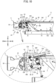
- the rotary body 6B comes into contact with the second section 87 of the cloth T from below.
- the second section 87 of the cloth T is clamped between the rotary body 6B and the lower surface 842 of the platen 84.
- the end effector 5A of the rotating mechanism 5 moves the pawl unit 51 further downward.
- the first joint 61 rotates in the counterclockwise direction around the rotary shaft 46 (an arrow Y35).
- the first joint 61 rotates further in the state in which the cloth T is clamped between the rotary body 6B and the platen 84 at the fourth step.
- the second joint 62 rotates in the clockwise direction around the rotary shaft 63 with respect to the first joint 61 (an arrow Y36).
- the spring 69 is compressed.
- the spring 69 urges the rotary body 6B toward the platen 84.
- the rotary body 6B moves to the front in the state in which the rotary body 6B is in contact with the second section 87 of the cloth T from below (an arrow Y37).
- the rotary body 6B since the first section 86 of the cloth T is clamped between the lower surface 220A of the plate body 22A and the platen 84, the movement of the first section 86 of the cloth T toward the front is restricted. Further, since the one-way clutch is built into the rotary body 6B, the rotary body 6B does not rotate in the second rotation direction D2 when moving toward the front. Thus, the second section 87 of the cloth T moves to the front in accordance with the movement of the rotary body 6B to the front. A part of the cloth T is removed from the platen 84 in a state in which the rotary body 6B has moved further to the front than the front end section 84F of the platen 84. A section of the cloth T that is not closely attached to the platen 84 (hereinafter referred to as a "removal section 80") is formed.
- the removal section 80 of the cloth T extends to the front from a section facing the upper surface 841 of the platen 84, is bent at a front end portion, and extends toward a section facing the lower surface 842 of the platen 84.
- the plate body 22A and the rotary body 6B clamp, from both sides in the up-down direction, a section of the removal section 80 separated to the rear from the bent section at the front end portion.
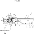
- the end effector 5A of the rotating mechanism 5 stops the downward movement of the pawl unit 51. In this way, the rotation of the first joint 61 is stopped.
- a region through which the rotary shaft 63 positioned at a connection section of the first joint 61 and the second joint 62 passes is indicated by a "movement trajectory U".
- a virtual plane extending along the lower surface 220A of the plate body 22A is indicated by a "virtual plane P".
- a part of the movement trajectory U passes on the opposite side to the first section 86 of the cloth T with respect to the virtual plane P, that is, passes above the virtual plane P.
- the removal device 20 moves to the front in accordance with the robot arm moving the end effector SAto the front (an arrow Y38).
- the cloth T moves to the front with respect to the platen unit 8, and is removed from the platen 84.
- the end effector 5A of the rotating mechanism 5 moves the pawl unit 51 upward (an arrow Y39).
- the first joint 61 rotates in the clockwise direction around the rotary shaft 46 (an arrow Y40).
- the rotary body 6B moves to the rear.
- the one-way clutch built into the rotary body 6B does not restrict the rotation of the rotary body 6B in the first rotation direction D1.
- the rotary body 6B rotates in the first rotation direction D1 in the course of moving to the rear while in contact with the plate body 22A.
- the rotary body 6B moves downward in accordance with the first joint 61 rotating further in the clockwise direction around the rotary shaft 46.
- the rotary body 6B moves away downward from the plate body 22A.
- the state of the cloth T being clamped by the plate body 22A and the rotary body 6B is released. In this way, it becomes possible to remove the cloth T from the removal device 20.
- the end effector 5A of the rotating mechanism 5 stops the upward movement of the pawl unit 51. In this way, the rotation of the first joint 61 is stopped.
- the removal device 20 moves the rotary bodies 6B and 7B to the front by the rotation of the first joints 61 and 71 in the state of causing the rotary bodies 6B and 7B of the second support portion 3 to be in contact with the second section 87 of the cloth T. In this way, the removal device 20 forms the removal section 80 in the cloth T, and moves the formed removal section 80, which is clamped by the first support portion 2 and the second support portion 3, to the front. As a result, the cloth T is removed from the platen 84. In this way, the removal device 20 contributes to removing the cloth T from the platen 84, even when there is no grip margin 80A on the cloth T.
- the removal device 20 contributes to suppressing a fold from being formed in the cloth T clamped by the first support portion 2 and the second support portion 3.
- the second support portion 3 includes the rotary bodies 6B and 7B as the sections that come into contact with the second section 87 of the cloth T.
- the rotary bodies 6B and 7B rotate in the course of the seventh step in which the cloth T is detached from the platen 84 and removed from the first support portion 2 and the second support portion 3 by the rotation of the first joints 61 and 71.
- the removal device 20 contributes to reducing a force necessary when the end effector 5A moves the pawl unit 51 upward for rotating the first joints 61 and 71.
- the removal device 20 contributes to facilitating a detaching operation of the cloth T by the end effector 5A.
- the second support portion 3 includes the link mechanisms 6A and 7A.
- the link mechanism 6A includes the first joint 61 and the second joint 62
- the link mechanism 7A includes the first joint 71 and the second joint 72.
- the removal device 20 transmits the force when the first joints 61 and 71 are rotated by the rotating mechanism 5 to the rotary bodies 6B and 7B, via the second joints 62 and 72. In this way, the removal device 20 contributes to moving the rotary bodies 6B and 7B to the front and removing the cloth T from the platen 84.
- the second support portion 3 includes the springs 69 and 79 that urge the rotary bodies 6B and 7B toward the platen 84.
- the rotary bodies 6B and 7B clamp the cloth T against the platen 84 with an appropriate amount of force using the urging force of the springs 69 and 79.
- the rotary bodies 6B and 7B appropriately clamp the cloth T against the platen 84, and contribute to removing the cloth T from the platen 84.
- the rotary bodies 6B and 7B contribute to improving an accuracy of the strength with which the rotary bodies 6B and 7B clamp the cloth T against the platen 84.
- the one-way clutches are built into the rotary bodies 6B and 7B.
- the one-way clutch contributes to restricting the rotation of the rotary bodies 6B and 7B in the second rotation direction D2 when removing the cloth T from the platen 84.
- the rotary bodies 6B and 7B contribute to clamping the cloth T against the platen 84 appropriately and removing the cloth T from the platen 84.
- the one-way clutch allows the rotary bodies 6B and 7B to rotate in the first rotation direction D1 in the course of the seventh step in which the cloth T is detached from the platen 84 and removed from the first support portion 2 and the second support portion 3 by rotating the first joints 61 and 71.
- the removal device 20 contributes to facilitating the operation of the end effector 5A of moving the pawl unit 51 upward and detaching the cloth T.
- the rotating mechanism 5 rotates the bridge portion 3C provided with the support shaft 33 around the rotary shaft 46 that is separated from the rotary shaft 46.
- the first joints 61 and 71 connected to the rectangular column body 31 of the bridge portion 3C also rotate around the rotary shaft 46 and the rotary bodies 6B and 7B move in the front-rear direction.
- the removal device 20 contributes to converting a linear operation in the up-down direction of the pawl unit 51 of the rotating mechanism 5 into a rotational operation by the bridge portion 3C, and to rotating the first joints 61 and 71 and moving the rotary bodies 6B and 7B in the front-rear direction.
- the first support portion 2 contributes to appropriately clamping the cloth T between the plate bodies 22A and 22B and the platen 84.
- the lower surfaces 220A and 220B are inclined with respect to the horizontal direction.
- the removal device 20 contributes to suppressing a contact area between the cloth T attached to the upper surface 841 of the platen 84 extending in the horizontal direction, and the lower surface 220A of the plate body 22A and the lower surface 220B of the plate body 22B.
- the removal device 20 contributes to reducing the possibility of the cloth T being contaminated by the contact of the plate bodies 22A and 22B with the cloth T.
- the rotary body 6B includes the rubber cylindrical body 65
- the rotary body 7B includes the rubber cylindrical body 75.
- the rubber plate 24A is exposed to the lower surface 220A of the plate body 22A
- the rubber plate 24B is exposed to the lower surface 220B of the plate body 22B.
- the removal device 20 contributes to causing the rotary bodies 6B and 7B, and the plate bodies 22A and 22B to attach closely to the cloth T.
- the removal device 20 contributes to appropriately clamping the cloth T using the first support portion 2 and the second support portion 3.
- the print system 1 is provided with the platen unit 8, the removal device 20, and the printer 9.
- the print system 1 contributes to the easy removal, from the platen 84 of the platen unit 8, using the removal device 20, the cloth T on which the printing has been performed by the printer 9 discharging the ink from the head 9A.
- the robot arm moves the removal device 20 in the front-rear direction.
- the print system 1 causes the removal device 20 to approach the platen unit 8 and remove the cloth T from the platen 84, and subsequently, causes the removal device 20 to move away from the platen unit 8.
- the print system 1 contributes to detaching the cloth T from the platen 84 using the removal device 20, while suppressing the conveyance of the platen unit 8 from being obstructed by the removal device 20.
- a frictional force acting on the plate body 22A due to the contact between the plate body 22A and the cloth T is denoted by "F22”.
- a pressing force by the rotary body 6B is denoted by “F10”.
- a reaction force acting on the plate body 22A is denoted by “F20”.
- a pulling force pulling the cloth T toward the platen 84 is denoted by "F0”.
- a distance between the virtual plane P and the center of the rotary shaft 63 is denoted by "L1”.
- a distance between the center of the rotary shaft 63 and the center of the rotary shaft 64 is denoted by "L2”.
- a rotational torque of the support body 62A of the second joint 62 is denoted by "Q”.
- a frictional coefficient of rubber is denoted by " ⁇ ".
- the reaction force F20 is a resultant force of the pressing force F 10, and a pressing force by the rotational torque Q.
- the pressing force by the rotational torque Q acts in the reverse direction (a loss direction) to the pressing force F 10.
- the term of "- ⁇ ⁇ L1/L2" corresponds to the loss.
- the larger L1 is, that is, the further downward the position of the rotary shaft 63, which is the rotational center of the support body 62A of the second joint 62, the larger the loss.
- the reaction force F20 is the resultant force of the pressing force F10 and the pressing force by the rotational torque Q.
- the pressing force of the rotational torque Q acts in the same direction as the pressing force F10.
- the friction increases by an amount corresponding to the term of " ⁇ ⁇ L1/L2".
- L1 is, that is, the further upward the position of the rotary shaft 63, which is the rotational center of the support body 62A of the second joint 62, the greater the contribution to obtaining the pressing force equal to or greater than the urging force of the spring 69.
- the removal device 20 contributes to maintaining the frictional force between the first support portion 2 and the cloth T, and the frictional force between the rotary bodies 6B and 7B of the second support portion 3 and the cloth T. As a result, the removal device 20 contributes to appropriately removing the cloth T from the platen 84.
- the first motor 15 is provided in place of the pawl unit 51 provided at the end effector 5A of the rotating mechanism 5.
- the rotary shaft 46 is connected to the first joints 61 and 71 of the second support portion 3.
- a rotary shaft of the first motor 15 is connected to the rotary shaft 46.
- the removal device 20 contributes to detaching the cloth T from the removal device 20 by moving the rotary bodies 6B and 7B to the rear, after the cloth T is removed from the platen 84 as a result of the removal device 20 moving to the front with respect to the platen 84.
- the removal device 20 contributes to efficiently transmitting the driving force of the rotating mechanism 5 and moving the rotary bodies 6B and 7B.
- a second motor 16A is provided in place of the urging mechanism 6C.
- the rotary shaft 63 of the second right support portion 3A is connected to the second joint 62 of the second right support portion 3A.
- a rotary shaft of the second motor 16A is connected to the rotary shaft 63.
- a second motor is also connected to the rotary shaft 73 of the second left support portion 3B in a similar manner to the second motor 16A.
- the second motor 16A provided in the second right support portion 3A, and the second motor provided in the second left support portion 3B will be collectively referred to as the "second motor 16".
- the cloth T is clamped between the platen 84 and the rotary bodies 6B and 7B, using a force of an appropriate strength, by the torque of the second motor 16. Further, by adjusting the torque of the second motor 16, the appropriate torque corresponding to a material of the cloth T is imparted to the rotary bodies 6B and 7B.
- the rotary bodies 6B and 7B contribute to appropriately clamping the cloth T between the platen 84 and the rotary bodies 6B and 7B, and removing the cloth T from the platen 84.
- a third motor 17A is used in place of the one-way clutch built into the rotary body 6B.
- the rotary shaft 64 is connected to the rotary body 6B.
- a rotary shaft of the third motor 17A is connected to the rotary shaft 64.
- a third motor is also connected to the rotary shaft 74 of the second left support portion 3B in a similar manner to the third motor 17A.
- the third motor 17A provided in the second right support portion 3A, and the third motor provided in the second left support portion 3B will be collectively referred to as the "third motor 17".
- the rotary bodies 6B and 7B may come into contact with a section, of the second section 87 of the cloth T, in the vicinity of the front end portion of the platen 84.
- the grip margin 80A having a sufficient size cannot be secured.
- the removal device 20 may rotate the rotary bodies 6B and 7B in the first rotation direction D1 using the third motor 17, after causing the rotary bodies 6B and 7B to come into contact with the second section 87 of the cloth T at the fourth step.
- a movement amount when moving the second section 87 of the cloth T to the front is larger than when the rotary bodies 6B and 7B do not rotate.
- the removal device 20 contributes to forming the grip margin 80A that is large enough in the cloth T, even when, due to the product configurations and the sizes of the removal device 20 and the platen 84, the rotary bodies 6B and 7B come into contact with a section, of the second section 87 of the cloth T, in the vicinity of the front end portion of the platen 84. In this way, the removal device 20 contributes to reliably clamping the cloth T using the rotary bodies 6B and 7B and the plate bodies 22A and 22B.
- the removal device 20 need not necessarily move in the front-rear direction, and instead, the platen unit 8 may move in the front-rear direction.
- the cloth T may be removed from the platen 84 after the platen unit 8 has moved in a direction approaching the removal device 20.
- the platen unit 8 including the platen 84 from which the cloth T has been removed may subsequently move in a direction away from the removal device 20.
- the removal device 20 may be provided integrally with the platen unit 8. In this case, the removal device 20 may be provided in each of a plurality of platen units.
- a printing method of the printer 9 is not limited to being an inkjet method, and a printer may perform the printing using a variety of methods.
- the removal device 20 may include only one of the first right support portion 2A and the first left support portion 2B, and may include only one of the second right support portion 3A and the second left support portion 3B.
- the second support portion 3 may include a movement mechanism capable of moving the rotary bodies 6B and 7B in the front-rear direction.
- the removal device 20 may remove the cloth T from the platen 84 by moving the rotary bodies 6B and 7B to the front in the horizontal direction.
- the rotary bodies 6B and 7B may be configured to be unable to rotate in both the first rotation direction D1 and the second rotation direction D2 with respect to the second joints 62 and 72.
- a rectangular column body, a plate body, or the like may be provided in place of the rotary bodies 6B and 7B.
- the second support portion 3 may remove the cloth T from the platen 84 by moving to the front in a state in which the rectangular column body, the plate body, or the like is caused to be in contact with the second section 87 of the cloth T.
- the urging mechanisms 6C and 7C may include torsion coil springs provided on the rotary shafts 63 and 73.
- the urging mechanisms 6C and 7C may urge the rotary bodies 6B and 7B toward the platen 84 by urging the second joints 62 and 72 using the torsion coil springs.
- the torsion coil springs By using the torsion coil springs, a space necessary for accommodating the second support portion 3 is made smaller, and this contributes to downsizing the removal device 20.
- the lower surfaces 220A and 220B of the plate bodies 22A and 22B of the first support portion 2 may extend horizontally.
- the first support portion 2 may include a rotary body in place of the plate bodies 22A and 22B of the first support portion 2. This rotary body may be configured to be rotatable by a motor.
- the lower surfaces 220A and 220B of the plate bodies 22A and 22B are not limited to being made of rubber, and another material may be used that has substantially the same coefficient of friction as rubber or a greater coefficient of friction than rubber.
- the rotary bodies 6B and 7B need not necessarily include the rubber cylindrical bodies 65 and 75.
- the rotary bodies 6B and 7B themselves may be made of rubber.
- the upward direction is an example of a "first direction” of the present invention.
- the downward direction is an example of a "second direction” of the present invention.
- the direction to the front is an example of a "third direction” of the present invention.
- the upper surface 841 of the platen 84 is an example of a "first surface” of the present invention.
- the lower surface 842 of the platen 84 is an example of a “second surface” of the present invention.
- the cloth T is an example of a "medium” of the present invention.
- the rotary bodies 6B and 7B are an example of a "second contact portion" of the present invention.
- the pawl unit 51 is an example of a "shaft support member" of the present invention.
- the support shaft 33 is an example of a "first shaft” of the present invention.
- the rotary shaft 46 is an example of a “second shaft” of the present invention.
- the end effector 5A is an example of a "movement mechanism” of the present invention.
- the lower surfaces 220A and 220B of the plate bodies 22A and 22B are an example of a "third surface” of the present invention.
Landscapes
- Engineering & Computer Science (AREA)
- Textile Engineering (AREA)
- Robotics (AREA)
- Mechanical Engineering (AREA)
- Handling Of Sheets (AREA)
Abstract
Description
- The present invention relates to a removal device that removes a medium from a platen, and a print system provided with the removal device.
- A print system is known that performs printing on a medium, such as a cloth or the like, held by a platen. A device is proposed for automatically performing an operation to remove the printed medium from the platen. In
JP 2020-110874 A - A robot hand of the robot arm normally grips a target object between a plurality of fingers. When it is attempted to remove a medium held on a platen using the robot hand, it is necessary for the robot hand to grip an excess section, of the medium, that is not mounted to the platen, using the plurality of fingers. Thus, when the excess section is not formed in the medium, there is a possibility that the robot arm may fail to remove the medium from the platen.
- An object of the present invention is to provide a removal device for realizing an operation of removing a medium from a platen even when the excess section is not formed in the medium, and a print system provided with the removal device.
- Various embodiments herein provide a first aspect of a removal device configured to remove a medium from a platen. The medium includes a first layer and a second layer. The first layer and the second layer connect with each other at one end of the medium and are separate from each other at the other end of the medium. During the medium being set on the platen, the first layer is over a first surface of the platen, the second layer is under a second surface of the platen, the one end of the medium is at a front end of the platen, and the other end of the medium is at a back end of the platen, respectively. The removal device includes a first support portion and a second support portion. The first support portion is configured to contact one of the first layer and the second layer of the medium. The second support portion includes a second contact portion. The second contact portion is configured to contact the other of the first layer and the second layer of the medium. The second contact portion includes a rotary body. The second contact portion is configured to move to the other of the first layer and the second layer of the medium. The second contact portion is configured to move in a forward direction in a state that the first support portion contacts the one of the first layer and the second layer of the medium and the rotary body of the second contact portion contacts the other of the first layer and the second layer of the medium.
- The removal device of the first aspect may further include a connecting portion positioned in front of the platen, and connecting the first support portion and the second support portion with each other. The second support portion may include a link mechanism. The link mechanism may include a first joint and a second j oint. One end of the first joint may be connected to the connecting portion. One end of the second joint may be connected to another end of the first joint. The rotary body may be provided at another end of the second joint. The removal device may further include a rotary mechanism configured to rotate the first joint with respect to the connecting portion.
- Various embodiments also provide a second aspect of a removal device that removes a medium from a platen. The medium includes a first section, a second section, and a third section. The first section extends along a first surface being an end surface of the platen in a first direction. The second section extends along a second surface being an end surface of the platen in a second direction opposite to the first direction. The third section joins the first section and the second section and is folded back at an end portion of the platen in a third direction orthogonal to the first direction and the second direction. The removal device includes a first support portion, a second support portion, and a connecting portion. The first support portion is positioned on an opposite side from the platen with respect to the first section of the medium in the first direction. The second support portion includes a second contact portion. The second contact portion is configured to move in the third direction, and coming into contact with a second opposite surface of the second section of the medium. The second opposite surface is on the opposite side to a second facing surface of the second section of the medium. The second facing surface faces the second surface of the platen. The connecting portion is positioned on the opposite side from the platen with respect to the first support portion and the second support portion in the third direction. The connecting portion is configured to connect the first support portion and the second support portion with each other.
- In the removal device of the second aspect, the second contact portion of the second support portion may move in the third direction in a state of contact with the second section of the medium. The first support portion may come into contact with a first opposite surface of the first section of the medium. The first opposite surface may be on the opposite side to a first facing surface of the first section of the medium. The first facing surface may face the first surface of the platen.
- In the removal device of the second aspect, the second contact portion may include a rotary body configured to rotate centered on a rotary shaft orthogonal to the first direction, the second direction, and the third direction.
- In the removal device of the second aspect, the second support portion may include a link mechanism. The link mechanism may include a first joint and a second joint. One end of the first joint may be connected to the connecting portion. One end of the second joint may be connected to another end of the first joint. The rotary body may be provided at another end of the second joint. The removal device may further include a rotary mechanism configured to rotate the first joint with respect to the connecting portion.
- The removal device of the second aspect may further include a spring configured to urge the rotary body toward the platen.
- In the removal device of the second aspect, the rotary body may include a one-way clutch. The one-way clutch may be configured to allow the rotary body to rotate in a first rotation direction and not allow the rotary body to rotate in a second rotation direction. The first rotation direction may be a rotation direction in which a contact section of the rotary body with the medium moves in the third direction. The second rotation direction may be opposite to the first rotation direction.
- In the removal device of the second aspect, the second support portion may include a first shaft. The rotary mechanism may include a shaft support member and a movement mechanism. The shaft may be configured to support the first shaft. The movement mechanism may be configured to move the shaft support member in the first direction and the second direction. The second support portion may be configured to rotate around a second shaft separated from the first shaft, as a result of the shaft support member moving in the first direction and the second direction.
- In the removal device of the second aspect, the rotary mechanism may include a first motor.
- The removal device of the second aspect may further include a second motor configured to rotate the second j oint with respect to the first joint.
- In the removal device of the second aspect, the first support portion may include a plate body including a third surface facing the first section of the medium.
- In the removal device of the second aspect, the third surface may be inclined with respect to a direction parallel to the first surface.
- In the removal device of the second aspect, the second contact portion may be made of rubber, and the third surface may be made of rubber.
- In the removal device of the second aspect, the second support portion may include a link mechanism. The link mechanism may include a first joint and a second joint. One end of the first joint may be connected to the connecting portion. One end of the second joint may be connected to another end of the first joint. The rotary body may be provided at another end of the second joint. The removal device may further include a rotary mechanism configured to rotate the first joint with respect to the connecting portion. When the first joint is rotated by the rotary mechanism, a movement trajectory of a connection section between the first joint and the second joint may pass farther to an opposite side of the first section of the medium in the first direction than a virtual plane extending along the third surface of the first support portion.
- The removal device of the first and the second aspect removes the medium from the platen by moving the second contact portion in the third direction in a state of the second section of the medium being caused to be in contact with the second contact portion of the second support portion. In this case, the removal device contributes to removing the medium from the platen even when an excess section is not formed in the medium.
- Various embodiments also provide a third aspect of a print system that includes a platen and a removal device. The removal device removes a medium from a platen. The medium includes a first section, a second section, and a third section. The first section extends along a first surface being an end surface of the platen in a first direction. The second section extends along a second surface being an end surface of the platen in a second direction opposite to the first direction. The third section joins the first section and the second section and is folded back at an end portion of the platen in a third direction orthogonal to the first direction and the second direction. The removal device includes a first support portion, a second support portion, and a connecting portion. The first support portion is positioned on an opposite side from the platen with respect to the first section of the medium in the first direction. The second support portion includes a second contact portion. The second contact portion is configured to move in the third direction, and coming into contact with a second opposite surface of the second section of the medium. The second opposite surface is on the opposite side to a second facing surface of the second section of the medium. The second facing surface faces the second surface of the platen. The connecting portion is positioned on the opposite side from the platen with respect to the first support portion and the second support portion in the third direction. The connecting portion is configured to connect the first support portion and the second support portion with each other.
- The print system of the third aspect may further include a head configured to print by ejecting ink onto the medium held on the platen.
- In the print system of the third aspect, the second support portion may include a rotary body configured to rotate centered on a rotary shaft orthogonal to the first direction, the second direction, and the third direction. The second support portion may include a link mechanism. The link mechanism may include a first joint and a second joint. One end of the first joint may be connected to the connecting portion. One end of the second joint may be connected to another end of the first joint. The rotary body may be provided at another end of the second joint. The print system may further include a rotary mechanism configured to rotate the first joint with respect to the connecting portion.
- The print system of the third aspect may further include a spring configured to urge the rotary body toward the platen.
- In the print system of the third aspect, the rotary body may include a one-way clutch. The one-way clutch may be configured to allow the rotary body to rotate in a first rotation direction and not allow the rotary body to rotate in a second rotation direction. The first rotation direction may be a rotation direction in which a contact section of the rotary body with the medium moves in the third direction. The second rotation direction may be opposite to the first rotation direction.
- In the print system of the third aspect, the first support portion may include a plate body including a third surface facing the first section of the medium. The third surface may be inclined with respect to a direction parallel to the first surface.
- In the print system of the third aspect, the removal device may be configured to move relative to the platen in a direction close to the platen and in a direction away from the platen.
-
-
FIG. 1 is a diagram showing an overview of a print system 1. -
FIG. 2 is a perspective view of aremoval device 20 and aplaten unit 8. -
FIG. 3 is a perspective view of theremoval device 20. -
FIG. 4 is a plan view of theremoval device 20. -
FIG. 5 is a cross-sectional view as seen in a direction of arrows along a line I-I shown inFIG. 4 . -
FIG. 6 is a diagram showing a first step of removing a cloth T from aplaten 84. -
FIG. 7 is a diagram showing a second step of removing the cloth T from theplaten 84. -
FIG. 8 is a diagram showing a third step of removing the cloth T from theplaten 84. -
FIG. 9 is a diagram showing a fourth step of removing the cloth T from theplaten 84. -
FIG. 10 is a diagram showing a fifth step of removing the cloth T from theplaten 84. -
FIG. 11 is a diagram showing a sixth step of removing the cloth T from theplaten 84. -
FIG. 12 is a diagram showing a seventh step of removing the cloth T from theplaten 84. -
FIG. 13 is an explanatory diagram for describing relationships between forces acting on theremoval device 20. -
FIG. 14 is an explanatory diagram for describing the relationships between forces acting on theremoval device 20. -
FIG. 15 is a right side view of theremoval device 20 including afirst motor 15, asecond motor 16A, and a third motor 17A. - An embodiment of a print system 1 according to the present invention will be described with reference to the drawings. The referenced drawings are used to illustrate technological features that can be adopted by the present invention. Illustrated configurations of devices and the like are not intended to limit the present invention to the embodiment alone, and are simply explanatory examples. An upward direction, a downward direction, a lower left direction, an upper right direction, an upper left direction, and a lower right direction in
FIG. 2 are, respectively, an upward direction, a downward direction, a front direction, a rear direction, a left direction, and a right direction of aremoval device 20 and aplaten unit 8. - As shown in
FIG. 1 , the print system 1 is provided with theremoval device 20, theplaten unit 8, and a printer 9. Theplaten unit 8 is conveyed in a state of a cloth T being held on aplaten 84. A type of the cloth T is not particularly limited. In the present embodiment, the cloth T is a T-shirt. Theplaten unit 8 is conveyed in a conveyance direction Y1. The printer 9 is provided at a part of a conveyance path of theplaten unit 8. The printer 9 is provided with ahead 9A that discharges ink. The printer 9 performs printing on the cloth T by discharging the ink from thehead 9A onto the cloth T held by theplaten 84. Theremoval device 20 is positioned downstream of the printer 9 in the conveyance direction Y1, on the conveyance path of theplaten unit 8. Theremoval device 20 moves in an approaching direction Y21, which is a direction from a position separated from the conveyance path of theplaten unit 8 toward a position close to the conveyance path, and in a separating direction Y22, which is a direction from the position close to the conveyance path of theplaten unit 8 toward the position separated from the conveyance path. Theremoval device 20 removes the cloth T, on which the printing by the printer 9 has been performed, from theplaten 84. - As shown in
FIG. 2 , the direction of the conveyance direction Y1 of theplaten unit 8 coincides with a direction to the left. Theplaten unit 8 is provided with abase 81, aright surface plate 82A, a left surface plate, arear surface plate 83, and theplaten 84. - The shape of the
base 81 is a rectangular shape in a plan view. Aright support portion 820A and aleft support portion 820B are fixed to the upper surface of thebase 81. Theright support portion 820A and theleft support portion 820B are separated from each other in the left-right direction. Theright support portion 820A is positioned to the right of theleft support portion 820B. - The
right surface plate 82A has a plate shape and is orthogonal to the left-right direction. Theright surface plate 82A includes afirst extension portion 821 and asecond extension portion 822. Thefirst extension portion 821 extends upward from a portion of theright support portion 820A further to the rear than a substantial center thereof in the front-rear direction. Thesecond extension portion 822 extends to the front from a front end portion of thefirst extension portion 821 and from a position separated upward from a lower end portion of thefirst extension portion 821. Thebase 81 and thesecond extension portion 822 are separated from each other in the up-down direction. The left surface plate has the same shape as theright surface plate 82A. A first extension portion of the left surface plate extends upward from a portion of theleft support portion 820B further to the rear than a substantial center thereof in the front-rear direction. A second extension portion of the left surface plate is separated upward from thebase 81. Theright surface plate 82A and the left surface plate are separated from each other in the left-right direction. Therear surface plate 83 has a plate shape and extends upward from a rear end portion of thebase 81. - The
platen 84 has a plate shape. In a plan view, the shape of theplaten 84 is a substantially rectangular shape that is long in the front-rear direction. Theplaten 84 includes anupper surface 841 and alower surface 842. Theupper surface 841 is an end surface of theplaten 84 in the upward direction. Thelower surface 842 is an end surface of theplaten 84 in the downward direction. Theupper surface 841 and thelower surface 842 extend horizontally, and are orthogonal to the up-down direction. Respective upper end portions of thesecond extension portion 822 of theright surface plate 82A and the second extension portion of the left surface plate are fixed to thelower surface 842 of theplaten 84. An end portion at the front of theplaten 84 will be referred to as a "front end section 84F". An end portion on the right of theplaten 84 will be referred to as a "right end section 84R". An end portion on the left of theplaten 84 will be referred to as a "left end section 84L". An end portion at the rear of theplaten 84 will be referred to as a "rear end section 84S". Thefront end section 84F, theright end section 84R, theleft end section 84L, and therear end section 84S extend in the up-down direction between theupper surface 841 and thelower surface 842, and join theupper surface 841 with thelower surface 842. Each of thefront end section 84F, theright end section 84R, and theleft end section 84L extend linearly. Therear end section 84S extends while curving. - The cloth T, such as the T-shirt or the like, is attached to the
platen 84. When the cloth T is attached to theplaten 84, a neck portion of the cloth T is positioned at thefront end section 84F of theplaten 84. The cloth T is in a state in which a section corresponding to thefront end section 84F of theplaten 84 is folded back. A hem section of the cloth T is positioned at therear end section 84S. - When mounting the cloth T to the
platen 84, the cloth T is stretched to the rear, to the left, and to the right such that the cloth T is not slack with respect to theupper surface 841 of theplaten 84. A section around the neck of the cloth T is closely attached to thefront end section 84F of theplaten 84. A section of the cloth T from the right sleeve to the hem is folded back at theright end section 84R of theplaten 84, and is fed between thelower surface 842 of theplaten 84 and thesecond extension portion 822 of theright surface plate 82A. A section of the cloth T from the left sleeve to the hem is folded back at theleft end section 84L of theplaten 84, and is fed between thelower surface 842 of theplaten 84 and the second extension portion of the left surface plate. - The approaching direction Y21 in which the
removal device 20 moves from the position separated from the conveyance path of theplaten unit 8 toward the position close to the conveyance path coincides with the direction to the rear. The separating direction Y22 in which theremoval device 20 moves from the position close to the conveyance path of theplaten unit 8 toward the position separated from the conveyance path coincides with the direction to the front. As shown inFIG. 3 to FIG. 5 , theremoval device 20 is provided with afirst support portion 2, asecond support portion 3, a connectingportion 4, and arotating mechanism 5. - The
rotating mechanism 5 includes anend effector 5A connected to a robot arm. The robot arm is a vertical articulated robot, and includes links and joints. Theend effector 5A is attached to a leading end of the robot arm. Aflat surface portion 50, which is orthogonal to the front-rear direction, is formed at a rear end portion of theend effector 5A. Theend effector 5A supports apawl unit 51 that protrudes to the rear from theflat surface portion 50. Thepawl unit 51 includes apawl 51A. Thepawl 51A has aU-shaped groove 51B. - The robot arm moves the
end effector 5A in at least the front-rear direction or the up-down direction. Further, theend effector 5A moves thepawl unit 51 in the up-down direction. - The connecting
portion 4 is connected to theend effector 5A. The connectingportion 4 moves in the front-rear direction or the up-down direction in accordance with the robot arm moving theend effector 5A. Further, the connectingportion 4 is provided to the front of thefirst support portion 2 and thesecond support portion 3 to be described later, and connects thefirst support portion 2 and thesecond support portion 3. - The connecting
portion 4 includes abase portion 41. Thebase portion 41 has a plate shape that is long in the left-right direction, and is orthogonal to the front-rear direction. A length in the up-down direction of thebase portion 41 is substantially the same as a length of theflat surface portion 50 of theend effector 5A. A length in the left-right direction of thebase portion 41 is longer than a length in the left-right direction of theflat surface portion 50 of theend effector 5A. Thebase portion 41 is connected to theend effector 5A. A central portion in the left-right direction of a front surface of thebase portion 41 faces theflat surface portion 50 of theend effector 5A. - A through
hole 50H is provided in the central portion in the left-right direction of thebase portion 41. Thepawl unit 51 extending from theflat surface portion 50 of theend effector 5A is inserted through the throughhole 50H, and protrudes further to the rear than a rear surface of thebase portion 41. - An upward extending
portion 42A is provided in the vicinity of a right end of thebase portion 41. An upward extendingportion 42B is provided in the vicinity of a left end of thebase portion 41. Each of the upward extendingportions base portion 41. - A rearward extending
portion 43A is provided in a rear surface of thebase portion 41, further to the right than a center thereof in the left-right direction. The rearward extendingportion 43A extends to the rear. The rearward extendingportion 43A has a plate shape, and is orthogonal to the left-right direction. Abridge portion 45Ais provided at a right surface of the rearward extendingportion 43A. Thebridge portion 45A has a rod shape and extends to the right. A rearward extendingportion 44A is provided at a right end portion of thebridge portion 45A. The rearward extendingportion 44A extends diagonally upward and to the rear. The rearward extendingportion 44A has a plate shape and is orthogonal to the left-right direction. The rearward extendingportions - A rearward extending
portion 43B is provided in the rear surface of thebase portion 41, further to the left than the center thereof in the left-right direction. The rearward extendingportion 43B extends to the rear. The rearward extendingportion 43B has a plate shape, and is orthogonal to the left-right direction. Abridge portion 45B is provided at a left surface of the rearward extendingportion 43B. Thebridge portion 45B has a rod shape and extends to the left. A rearward extendingportion 44B is provided at a left end portion of thebridge portion 45B. The rearward extendingportion 44B extends diagonally upward and to the rear. The rearward extendingportion 44B has a plate shape and is orthogonal to the left-right direction. The rearward extendingportions - A through hole that extends in the left-right direction is provided in each of rear end portion of each of the rearward extending
portions portions - The
first support portion 2 is in contact with the cloth T attached to theplaten 84 from above, and supports the cloth T. Thefirst support portion 2 includes a firstright support portion 2A and a firstleft support portion 2B. The firstright support portion 2A and the firstleft support portion 2B have the same shape. - The first
right support portion 2A includes anextension portion 21A and aplate body 22A. Theextension portion 21A has a plate shape and is orthogonal to the up-down direction. Theextension portion 21A extends toward the rear from an upper end portion of the upward extendingportion 42A of the connectingportion 4. Theplate body 22A is connected to a rear end portion of theextension portion 21A. Theplate body 22A includes abase plate 23A and arubber plate 24A. Thebase plate 23A is made of metal, and therubber plate 24A is made of rubber. Therubber plate 24A is bonded to a lower surface of thebase plate 23A. - The
plate body 22A extends diagonally upward and to the rear from a connection portion with theextension portion 21A. Therubber plate 24A is exposed to alower surface 220A of theplate body 22A. Thelower surface 220A is inclined with respect to the horizontal direction. A direction orthogonal to thelower surface 220A and oriented in the opposite direction to thebase plate 23A is oriented diagonally to the rear and downward. - The first
left support portion 2B includes anextension portion 21B and aplate body 22B. Theextension portion 21B extends toward the rear from an upper end portion of the upward extendingportion 42B of the connectingportion 4. Theplate body 22B includes abase plate 23B and arubber plate 24B. Theextension portion 21B, theplate body 22B, thebase plate 23B, and therubber plate 24B correspond to theextension portion 21A, theplate body 22A, thebase plate 23A, and therubber plate 24A of the firstright support portion 2A. Alower surface 220B of theplate body 22B corresponds to thelower surface 220A of theplate body 22A. - The
second support portion 3 is in contact with the cloth T attached to theplaten 84 from below, and supports the cloth T. Thesecond support portion 3 includes a secondright support portion 3A, a secondleft support portion 3B, and abridge portion 3C. The secondright support portion 3A and the secondleft support portion 3B have the same shape. Thebridge portion 3C spans between the secondright support portion 3A and the secondleft support portion 3B. - The second
right support portion 3A includes alink mechanism 6A. Thelink mechanism 6A includes a first joint 61 and a second joint 62. - The first joint 61 includes plate-shaped
support bodies support bodies support bodies support body 61A is positioned to the left of the rearward extendingportion 44A of the connectingportion 4. Thesupport body 61B is positioned to the right of the rearward extendingportion 43A of the connectingportion 4. - The
support body 61A includes extendingportions portion 44A of the connectingportion 4. Directions in which the respective extendingportions portions support body 61B extend from a section at the right of the rearward extendingportion 43A of the connectingportion 4. In each of thesupport bodies portions - A
rotary shaft 46 has a circular column shape, and extends in the left-right direction. Therotary shaft 46 is inserted through the through holes of each of the rearward extendingportions portion 4, and through the through holes of each of thesupport bodies portion 4 centered on therotary shaft 46. - The first joint 61 further includes a
bridge body 61C and arotary shaft 63. Thebridge body 61C is provided between leading end portions of the extendingportions 602 of each of thesupport bodies bridge body 61C. Therotary shaft 63 has a circular column shape, and extends in the left-right direction. Therotary shaft 63 is inserted through through holes provided in leading end portions of the extendingportions 601 of each of thesupport bodies rotary shaft 63 protrudes further to the right than thesupport body 61A. A left end portion of therotary shaft 63 protrudes further to the left than thesupport body 61B. - The second joint 62 includes plate-shaped
support bodies support bodies support body 62A is positioned to the right of the leading end portion of the extendingportion 601 of thesupport body 61A of the first joint 61. The section of therotary shaft 63 that protrudes further to the right than thesupport body 61A is inserted through a through hole provided in the one end portion of thesupport body 62A. One end portion of thesupport body 62B is positioned to the left of the leading end portion of the extendingportion 601 of thesupport body 61B of the first joint 61. The section of therotary shaft 63 that protrudes further to the left than thesupport body 61B is inserted through a through hole provided in the one end portion of thesupport body 62B. The second joint 62 is supported so as to be rotatable around therotary shaft 63 with respect to the first joint 61. - The second joint 62 further includes a
rotary shaft 64. Therotary shaft 64 is inserted through through holes provided in other end portions of each of thesupport bodies rotary shaft 64 extends between the other end portions of each of thesupport bodies - The second
right support portion 3A further includes arotary body 6B. Therotary body 6B has a circular column shape. A center axis of therotary body 6B extends in the left-right direction. A through hole along the center axis is formed in therotary body 6B. Therotary shaft 64 is inserted through the through hole of therotary body 6B. Therotary body 6B is supported so as to be rotatable around therotary shaft 64 between the other end portions of each of thesupport bodies rotary body 6B includes a rubbercylindrical body 65. By causing an outer peripheral surface of the rubbercylindrical body 65 to come into contact with the cloth T, therotary body 6B pulls the cloth T. - A one-way clutch is built into the
rotary body 6B. The one-way clutch allows therotary body 6B to rotate in the counterclockwise direction in a right side view (hereinafter referred to as a "first rotation direction D1"). On the other hand, the one-way clutch prohibits therotary body 6B from rotating in the clockwise direction in a right side view (hereinafter referred to as a "second rotation direction D2"). - The second
right support portion 3A further includes an urging mechanism 6C. The urging mechanism 6C includes aclamp 67, asupport rod 68, and aspring 69. Theclamp 67 includes a pair of shaft bearing portions positioned on both the left and right of therotary body 6B, and a bridge portion stretched between the pair of shaft bearing portions. Thesupport rod 68 extends from the bridge portion of theclamp 67 toward thebridge body 61C of the first joint 61. Of thesupport rod 68, an end portion on the opposite side to theclamp 67 is inserted through the through hole in thebridge body 61C. Thespring 69 is a compression coil spring. Thespring 69 is interposed between theclamp 67 and thebridge body 61C. Thespring 69 urges therotary shaft 64 and therotary body 6B, via theclamp 67. A force acts on therotary body 6B in a direction away from thebridge body 61C. - The second
left support portion 3B includes alink mechanism 7A, arotary body 7B, and anurging mechanism 7C. Thelink mechanism 7A includes a first joint 71 and a second joint 72. The first joint 71 includessupport bodies bridge body 71C, and arotary shaft 73. The second joint 72 includessupport bodies rotary shaft 74. Therotary body 7B includes a rubbercylindrical body 75. Theurging mechanism 7C includes aclamp 77, asupport rod 78, and aspring 79. - The extending
portions support portion 71A of the first joint 71 extend from a section at the left of the rearward extendingportion 43B of the connectingportion 4. The extendingportions support portion 71B of the first joint 71 extend from a section at the right of the rearward extendingportion 44B of the connectingportion 4. In each of thesupport bodies rotary shaft 46 is inserted through through holes formed at sections at which the extendingportions portion 4 centered on therotary shaft 46. The second joint 72 is supported so as to be rotatable around therotary shaft 73 with respect to the first joint 71, at each of one end portions of thesupport bodies rotary body 7B is supported so as to be rotatable around therotary shaft 74, between each of other end portions of thesupport bodies - A one-way clutch is built into the
rotary body 7B. The one-way clutch allows therotary body 7B to rotate in the first rotation direction D1. On the other hand, the one-way clutch prohibits therotary body 7B from rotating in the second rotation direction D2. - A pair of shaft bearing portions of the
clamp 77 of theurging mechanism 7C are positioned on both the left and right of therotary body 7B. Thesupport rod 78 of theclamp 77 extends from a bridge portion of theclamp 77 toward thebridge body 71C of the first joint 71. Of thesupport rod 78, an end portion on the opposite side to theclamp 77 is inserted through a through hole in thebridge body 71C. Thespring 79 is interposed between theclamp 77 and thebridge body 71C. Thespring 79 urges therotary shaft 74 and therotary body 7B, via theclamp 77. A force acts on therotary body 7B in a direction away from thebridge body 71C. - The
bridge portion 3C includes arectangular column body 31 that extends in the left-right direction. Therectangular column body 31 is respectively connected to upper end portions of the extendingportions 601 of each of thesupport bodies right support portion 3A and of the extendingportions 601 of each of thesupport bodies left support portion 3B. - The
bridge portion 3C further includes an extendingbody 32 that extends from therectangular column body 31. The extendingbody 32 is connected to a central section, in the left-right direction, of a lower end surface of therectangular column body 31, and extends diagonally to the front and downward. A through hole extending to the left and right is formed in a lower end portion of the extendingbody 32. Therotary shaft 46 is inserted through the through hole of the extendingbody 32. Thebridge portion 3C can rotate around therotary shaft 46 together with the first joint 61 of the secondright support portion 3A and the first joint 71 of the secondleft support portion 3B connected to therectangular column body 31. -
Support bodies body 32, in which the through hole is formed through which therotary shaft 46 is inserted. Thesupport bodies support bodies support shaft 33 is provided between rear end portions of each of thesupport bodies support shaft 33 has a circular column shape, and extends in the left-right direction. Thesupport shaft 33 fits into theU-shaped groove 51B of thepawl 51A of thepawl unit 51 extending from theend effector 5A of therotating mechanism 5. - When the
end effector 5A moves thepawl unit 51 in the up-down direction and thus moves thesupport shaft 33 in the up-down direction, thesupport shaft 33 of thebridge portion 3C fitted into theU-shaped groove 51B also moves in the up-down direction. Thebridge portion 3C rotates around therotary shaft 46 that is separated from thesupport shaft 33, in accordance with the movement of thesupport shaft 33 in the up-down direction. In accordance with the rotation of thebridge portion 3C, the first joint 61 of thelink mechanism 6A of the secondright support portion 3A and the first joint 71 of thelink mechanism 7A of the secondleft support portion 3B that are connected via therectangular column body 31 also rotate around therotary shaft 46. Further, therotary body 6B supported by the second joint 62 rotates in accordance with the rotation of the first joint 61 of thelink mechanism 6A. Therotary body 7B supported by the second joint 72 rotates in accordance with the rotation of the first joint 71 of thelink mechanism 7A. - A direction K1 is defined that extends along the
support bodies right support portion 3A and is a direction from a center of therotary shaft 46 toward a center of therotary shaft 63. The direction K1 coincides with the direction that extends along thesupport bodies left support portion 3B and the direction that is from the center of therotary shaft 46 to the center of therotary shaft 63. A direction K2 extending horizontally to the rear from the center of therotary shaft 46 is defined. An angle formed by the directions K1 and K2 will be referred to as an "angle θ of thefirst joints - Each of steps (a first step to a seventh step) for removing the cloth T attached to the
platen 84 of theplaten unit 8 using theremoval device 20 will be described with reference toFIG. 6 to FIG. 12 . In the following description, operations of the firstright support portion 2A of thefirst support portion 2, and the secondright support portion 3A of thesecond support portion 3 of theremoval device 20 will be described, but the firstleft support portion 2B of thefirst support portion 2, and the secondleft support portion 3B of thesecond support portion 3 of theremoval device 20 operate in the same manner. Unless otherwise described, it is assumed that rotation directions (the clockwise direction or the counterclockwise direction) are described assuming a state of theremoval device 20 being viewed from the right. - At the first step shown in
FIG. 6 , a user attaches the cloth T to theplaten 84. Of the cloth T, a section extending along theupper surface 841 of theplaten 84 will be referred to as a "first section 86", and a section facing thelower surface 842 of theplaten 84 will be referred to as a "second section 87". Of the cloth T, a section folded back at thefront end section 84F of theplaten 84, that is, a section around the neck of the T-shirt, will be referred to as a "third section 88". Theremoval device 20 is disposed at a position separated to the front from theplaten 84. With respect to the firstright support portion 2A, the connectingportion 4 of theremoval device 20 is positioned on the opposite side from theplaten unit 8 in the front-rear direction. The angle θ of the first joint 61 is approximately 30 degrees. - At the second step shown in
FIG. 7 , in accordance with the robot arm moving theend effector 5A to the rear, theremoval device 20 moves to the rear (the direction of an arrow Y31). Theremoval device 20 approaches theplaten unit 8, which is to the rear thereof, from the front. The firstright support portion 2A is positioned further in the upward direction than thefirst section 86 of the cloth T in the up-down direction. Theplate body 22A is separated upward from theupper surface 841 of theplaten 84 and thefirst section 86 of the cloth T. Thelower surface 220A of theplate body 22A faces thefirst section 86 of the cloth T. The secondright support portion 3A is positioned further in the downward direction than thesecond section 87 of the cloth T in the up-down direction. Therotary body 6B is separated downward from thelower surface 842 of theplaten 84 and thesecond section 87 of the cloth T. - At the third step shown in
FIG. 8 , in accordance with the robot arm moving theend effector 5A downward, theremoval device 20 moves downward (the direction of an arrow Y32). Theplate body 22A approaches theplaten 84 from above. Thelower surface 220A of theplate body 22A comes into contact with the surface, of the cloth T, on the opposite side from the surface thereof facing theplaten 84. The cloth T is clamped from both sides in the up-down direction by theplate body 22A and theplaten 84. After theplate body 22A has come into contact with the cloth T, the robot arm stops the downward movement of theend effector 5A. In this way, the downward movement of theremoval device 20 also stops. - Here, in contrast to the fact that the
upper surface 841 of theplaten 84 is extending in the horizontal direction, thelower surface 220A of theplate body 22A is inclined with respect to the horizontal direction. Thus, in accordance with theplate body 22A coming into contact with theplaten 84, a boundary section between thefirst section 86 and thethird section 88 of the cloth T attached to theplaten 84 comes into contact with thelower surface 220A of theplate body 22A. - At the fourth step shown in
FIG. 9 , theend effector 5A of therotating mechanism 5 moves thepawl unit 51 downward (an arrow Y33). In this way, the first joint 61 rotates by approximately 15 degrees in the counterclockwise direction around the rotary shaft 46 (an arrow Y34). The angle θ of the first joint 61 becomes approximately 45 degrees. - In accordance with the rotation of the first joint 61, the
rotary body 6B connected to the first joint 61 via the second joint 62 moves upward. Therotary body 6B comes into contact with thesecond section 87 of the cloth T from below. In accordance with therotary body 6B moving further upward, thesecond section 87 of the cloth T is clamped between therotary body 6B and thelower surface 842 of theplaten 84. - At the fifth step shown in
FIG. 10 , theend effector 5A of therotating mechanism 5 moves thepawl unit 51 further downward. In this way, the first joint 61 rotates in the counterclockwise direction around the rotary shaft 46 (an arrow Y35). At the fifth step, the first joint 61 rotates further in the state in which the cloth T is clamped between therotary body 6B and theplaten 84 at the fourth step. Thus, the second joint 62 rotates in the clockwise direction around therotary shaft 63 with respect to the first joint 61 (an arrow Y36). In this way, thespring 69 is compressed. Thespring 69 urges therotary body 6B toward theplaten 84. After the angle θ of the first joint 61 exceeds 90 degrees, therotary body 6B moves to the front in the state in which therotary body 6B is in contact with thesecond section 87 of the cloth T from below (an arrow Y37). - Note that since the
first section 86 of the cloth T is clamped between thelower surface 220A of theplate body 22A and theplaten 84, the movement of thefirst section 86 of the cloth T toward the front is restricted. Further, since the one-way clutch is built into therotary body 6B, therotary body 6B does not rotate in the second rotation direction D2 when moving toward the front. Thus, thesecond section 87 of the cloth T moves to the front in accordance with the movement of therotary body 6B to the front. A part of the cloth T is removed from theplaten 84 in a state in which therotary body 6B has moved further to the front than thefront end section 84F of theplaten 84. A section of the cloth T that is not closely attached to the platen 84 (hereinafter referred to as a "removal section 80") is formed. - The
removal section 80 of the cloth T extends to the front from a section facing theupper surface 841 of theplaten 84, is bent at a front end portion, and extends toward a section facing thelower surface 842 of theplaten 84. Theplate body 22A and therotary body 6B clamp, from both sides in the up-down direction, a section of theremoval section 80 separated to the rear from the bent section at the front end portion. - When the angle θ of the first joint 61 has become approximately 100 degrees, the
end effector 5A of therotating mechanism 5 stops the downward movement of thepawl unit 51. In this way, the rotation of the first joint 61 is stopped. - At the fifth step, a region through which the
rotary shaft 63 positioned at a connection section of the first joint 61 and the second joint 62 passes is indicated by a "movement trajectory U". A virtual plane extending along thelower surface 220A of theplate body 22A is indicated by a "virtual plane P". At this time, a part of the movement trajectory U passes on the opposite side to thefirst section 86 of the cloth T with respect to the virtual plane P, that is, passes above the virtual plane P. - At the sixth step shown in
FIG. 11 , theremoval device 20 moves to the front in accordance with the robot arm moving the end effector SAto the front (an arrow Y38). The cloth T moves to the front with respect to theplaten unit 8, and is removed from theplaten 84. - At the seventh step shown in
FIG. 12 , theend effector 5A of therotating mechanism 5 moves thepawl unit 51 upward (an arrow Y39). In this way, the first joint 61 rotates in the clockwise direction around the rotary shaft 46 (an arrow Y40). Therotary body 6B moves to the rear. Note that the one-way clutch built into therotary body 6B does not restrict the rotation of therotary body 6B in the first rotation direction D1. Thus, therotary body 6B rotates in the first rotation direction D1 in the course of moving to the rear while in contact with theplate body 22A. - The
rotary body 6B moves downward in accordance with the first joint 61 rotating further in the clockwise direction around therotary shaft 46. Therotary body 6B moves away downward from theplate body 22A. The state of the cloth T being clamped by theplate body 22A and therotary body 6B is released. In this way, it becomes possible to remove the cloth T from theremoval device 20. - When the angle θ of the first joint 61 has become approximately 30 degrees, the
end effector 5A of therotating mechanism 5 stops the upward movement of thepawl unit 51. In this way, the rotation of the first joint 61 is stopped. - The
removal device 20 moves therotary bodies first joints rotary bodies second support portion 3 to be in contact with thesecond section 87 of the cloth T. In this way, theremoval device 20 forms theremoval section 80 in the cloth T, and moves the formedremoval section 80, which is clamped by thefirst support portion 2 and thesecond support portion 3, to the front. As a result, the cloth T is removed from theplaten 84. In this way, theremoval device 20 contributes to removing the cloth T from theplaten 84, even when there is nogrip margin 80A on the cloth T. - In the course of the cloth T being removed from the
platen 84, of thegrip margin 80A of the cloth T, the bent section at the front end portion is not directly clamped by thefirst support portion 2 and thesecond support portion 3. Thus, theremoval device 20 contributes to suppressing a fold from being formed in the cloth T clamped by thefirst support portion 2 and thesecond support portion 3. - The
second support portion 3 includes therotary bodies second section 87 of the cloth T. Therotary bodies platen 84 and removed from thefirst support portion 2 and thesecond support portion 3 by the rotation of thefirst joints rotary bodies removal device 20 contributes to reducing a force necessary when theend effector 5A moves thepawl unit 51 upward for rotating thefirst joints removal device 20 contributes to facilitating a detaching operation of the cloth T by theend effector 5A. - The
second support portion 3 includes thelink mechanisms link mechanism 6A includes the first joint 61 and the second joint 62, and thelink mechanism 7A includes the first joint 71 and the second joint 72. Theremoval device 20 transmits the force when thefirst joints rotating mechanism 5 to therotary bodies second joints removal device 20 contributes to moving therotary bodies platen 84. - The
second support portion 3 includes thesprings rotary bodies platen 84. Therotary bodies platen 84 with an appropriate amount of force using the urging force of thesprings rotary bodies platen 84, and contribute to removing the cloth T from theplaten 84. Note that, compared to a case in which another type of spring is used, by using the compression springs as thesprings rotary bodies rotary bodies platen 84. - The one-way clutches are built into the
rotary bodies rotary bodies platen 84. Thus, therotary bodies platen 84 appropriately and removing the cloth T from theplaten 84. On the other hand, the one-way clutch allows therotary bodies platen 84 and removed from thefirst support portion 2 and thesecond support portion 3 by rotating thefirst joints removal device 20 contributes to facilitating the operation of theend effector 5A of moving thepawl unit 51 upward and detaching the cloth T. - As a result of the
pawl unit 51 moving thesupport shaft 33 in the up-down direction, therotating mechanism 5 rotates thebridge portion 3C provided with thesupport shaft 33 around therotary shaft 46 that is separated from therotary shaft 46. In this case, thefirst joints rectangular column body 31 of thebridge portion 3C also rotate around therotary shaft 46 and therotary bodies removal device 20 contributes to converting a linear operation in the up-down direction of thepawl unit 51 of therotating mechanism 5 into a rotational operation by thebridge portion 3C, and to rotating thefirst joints rotary bodies - The
lower surface 220A of theplate body 22A of thefirst support portion 2, and thelower surface 220B of theplate body 22B face thefirst section 86 of the cloth T attached to theplaten 84. Thefirst support portion 2 contributes to appropriately clamping the cloth T between theplate bodies platen 84. Note that thelower surfaces removal device 20 contributes to suppressing a contact area between the cloth T attached to theupper surface 841 of theplaten 84 extending in the horizontal direction, and thelower surface 220A of theplate body 22A and thelower surface 220B of theplate body 22B. Thus, theremoval device 20 contributes to reducing the possibility of the cloth T being contaminated by the contact of theplate bodies - The
rotary body 6B includes the rubbercylindrical body 65, and therotary body 7B includes the rubbercylindrical body 75. Therubber plate 24A is exposed to thelower surface 220A of theplate body 22A, and therubber plate 24B is exposed to thelower surface 220B of theplate body 22B. Thus, theremoval device 20 contributes to causing therotary bodies plate bodies removal device 20 contributes to appropriately clamping the cloth T using thefirst support portion 2 and thesecond support portion 3. - The print system 1 is provided with the
platen unit 8, theremoval device 20, and the printer 9. The print system 1 contributes to the easy removal, from theplaten 84 of theplaten unit 8, using theremoval device 20, the cloth T on which the printing has been performed by the printer 9 discharging the ink from thehead 9A. - The robot arm moves the
removal device 20 in the front-rear direction. In this way, the print system 1 causes theremoval device 20 to approach theplaten unit 8 and remove the cloth T from theplaten 84, and subsequently, causes theremoval device 20 to move away from theplaten unit 8. Thus, the print system 1 contributes to detaching the cloth T from theplaten 84 using theremoval device 20, while suppressing the conveyance of theplaten unit 8 from being obstructed by theremoval device 20. - In contrast to the present embodiment, an example will be described of a case in which the movement trajectory U of the center of the
rotary shaft 63 of the secondright support portion 3A is positioned lower than the virtual plane P. As shown inFIG. 13 , a frictional force acting on the lower surface of the cloth T due to the contact between therotary body 6B and the cloth T is denoted by "F11". A frictional force acting on therotary body 6B due to the contact between therotary body 6B and the cloth T is denoted by "F12". A frictional force acting on the upper surface of the cloth T due to the contact between theplate body 22A and the cloth T is denoted by "F21". A frictional force acting on theplate body 22A due to the contact between theplate body 22A and the cloth T is denoted by "F22". A pressing force by therotary body 6B is denoted by "F10". A reaction force acting on theplate body 22A is denoted by "F20". A pulling force pulling the cloth T toward theplaten 84 is denoted by "F0". A distance between the virtual plane P and the center of therotary shaft 63 is denoted by "L1". A distance between the center of therotary shaft 63 and the center of therotary shaft 64 is denoted by "L2". A rotational torque of thesupport body 62A of the second joint 62 is denoted by "Q". A frictional coefficient of rubber is denoted by "µ". - Taking into account an equilibrium relationship of the forces, the following relationships are satisfied:


- The reaction force F20 is a resultant force of the pressing force F 10, and a pressing force by the rotational torque Q. The pressing force by the rotational torque Q acts in the reverse direction (a loss direction) to the pressing force F 10. Thus, the following relationships are satisfied.
F20 = F10 - Q/L2 = F10 - F12 × L1/L2 = F10 - (µ × F10) × L1/L2 = (1 - µ × L1/L2) × F10 - Thus, the pulling force F0 pulling the cloth T toward the
platen 84 satisfies the following relationships.F0 = F11 + F21 = µ × (F10 + F20) = µ × (F10 + (1 - µ × L1/L2) × F10) = µ × F10 × (2 - µ × L1/L2) - In other words, the term of "- µ × L1/L2" corresponds to the loss. Thus, for example, the larger L1 is, that is, the further downward the position of the
rotary shaft 63, which is the rotational center of thesupport body 62A of the second joint 62, the larger the loss. - On the other hand, as in the present embodiment, the example is described of the case in which a part of the movement trajectory U of the center of the
rotary shaft 63 of the secondright support portion 3A is higher than the virtual plane P. As shown inFIG. 14 , the reaction force F20 is the resultant force of the pressing force F10 and the pressing force by the rotational torque Q. The pressing force of the rotational torque Q acts in the same direction as the pressing force F10. Thus, the following relationships are satisfied.F20 = F10 - Q/L2 = F10 + F12 × L1/L2 = F10 + (µ × F10) × L1/L2 = (1 + µ × L1/L2) × F10 - Thus, the pulling force F0 pulling the cloth T toward the
platen 84 satisfies the following relationships.F0 = F11 + F21 = µ × (F10 + F20) = µ × (F10 + (1 + µ × L1/L2) × F10) = µ × F10 × (2 + µ × L1/L2) - In other words, the friction increases by an amount corresponding to the term of "µ × L1/L2". Thus, for example, the larger L1 is, that is, the further upward the position of the
rotary shaft 63, which is the rotational center of thesupport body 62A of the second joint 62, the greater the contribution to obtaining the pressing force equal to or greater than the urging force of thespring 69. - Thus, by causing the
rotary shaft 63 to be disposed such that a part of the movement trajectory U thereof passes higher than the virtual plane P, theremoval device 20 contributes to maintaining the frictional force between thefirst support portion 2 and the cloth T, and the frictional force between therotary bodies second support portion 3 and the cloth T. As a result, theremoval device 20 contributes to appropriately removing the cloth T from theplaten 84. - The
removal device 20 may be further provided with at least one of afirst motor 15, asecond motor 16, and a third motor 17, as shown inFIG 15 . Specifically, this is as follows. - The
first motor 15 is provided in place of thepawl unit 51 provided at theend effector 5A of therotating mechanism 5. In this case, therotary shaft 46 is connected to thefirst joints second support portion 3. A rotary shaft of thefirst motor 15 is connected to therotary shaft 46. When therotary shaft 46 rotates due to the driving of thefirst motor 15, thefirst joints rotary shaft 46 rotate with respect to the connectingportion 4. In this way, therotary bodies second support portion 3 can move in the front-rear direction. - As described above, when the
first motor 15 is provided in theremoval device 20, a force when thefirst joints first motor 15 is transmitted to therotary bodies second joints removal device 20 contributes to detaching the cloth T from theremoval device 20 by moving therotary bodies platen 84 as a result of theremoval device 20 moving to the front with respect to theplaten 84. Further, compared to the case in which the linear operation of thepawl unit 51 is converted into the rotational operation by thebridge portion 3C and therotary bodies removal device 20 contributes to efficiently transmitting the driving force of therotating mechanism 5 and moving therotary bodies - A
second motor 16A is provided in place of the urging mechanism 6C. In this case, therotary shaft 63 of the second right support portion 3Ais connected to the second joint 62 of the secondright support portion 3A. A rotary shaft of thesecond motor 16A is connected to therotary shaft 63. When therotary shaft 63 rotates due to the driving force of thesecond motor 16A, the second joint 62 connected to therotary shaft 63 rotates with respect to the first joint 61. In this case, therotary body 6B supported by the second joint 62 also rotates. - Note that, although a description thereof is omitted, a second motor is also connected to the
rotary shaft 73 of the secondleft support portion 3B in a similar manner to thesecond motor 16A. Hereinafter, thesecond motor 16A provided in the secondright support portion 3A, and the second motor provided in the secondleft support portion 3B will be collectively referred to as the "second motor 16". - In this way, when the
second motor 16 is provided in theremoval device 20, the cloth T is clamped between theplaten 84 and therotary bodies second motor 16. Further, by adjusting the torque of thesecond motor 16, the appropriate torque corresponding to a material of the cloth T is imparted to therotary bodies rotary bodies platen 84 and therotary bodies platen 84. - A third motor 17A is used in place of the one-way clutch built into the
rotary body 6B. In this case, therotary shaft 64 is connected to therotary body 6B. A rotary shaft of the third motor 17A is connected to therotary shaft 64. When the third motor 17A is in an excited state, the rotation of therotary shaft 64 is restricted, and thus, the rotation of therotary body 6B is also restricted. On the other hand, when the excited state of the third motor 17A is cancelled, therotary shaft 64 is able to rotate, and thus the rotation of therotary body 6B is also possible. - Note that, although a description thereof is omitted, a third motor is also connected to the
rotary shaft 74 of the secondleft support portion 3B in a similar manner to the third motor 17A. Hereinafter, the third motor 17A provided in the secondright support portion 3A, and the third motor provided in the secondleft support portion 3B will be collectively referred to as the "third motor 17". - In this way, when the third motor 17 is provided in the
removal device 20, by causing the third motor 17 to be in the excited state, when detaching the cloth T from theplaten 84, the rotation of therotary bodies platen 84, from theremoval device 20, therotary bodies - Note that, depending on a product configuration and size of the cloth T, at the fourth step shown in
FIG. 9 , therotary bodies second section 87 of the cloth T, in the vicinity of the front end portion of theplaten 84. In this case, at the fifth step shown inFIG. 10 , even when therotary bodies grip margin 80A having a sufficient size cannot be secured. - In this type of case, for example, the
removal device 20 may rotate therotary bodies rotary bodies second section 87 of the cloth T at the fourth step. In this case, with theremoval device 20, a movement amount when moving thesecond section 87 of the cloth T to the front is larger than when therotary bodies removal device 20 contributes to forming thegrip margin 80A that is large enough in the cloth T, even when, due to the product configurations and the sizes of theremoval device 20 and theplaten 84, therotary bodies second section 87 of the cloth T, in the vicinity of the front end portion of theplaten 84. In this way, theremoval device 20 contributes to reliably clamping the cloth T using therotary bodies plate bodies - The present invention is not limited to the above-described embodiment and modified example, and various changes are possible. In the print system 1, the
removal device 20 need not necessarily move in the front-rear direction, and instead, theplaten unit 8 may move in the front-rear direction. In this case, the cloth T may be removed from theplaten 84 after theplaten unit 8 has moved in a direction approaching theremoval device 20. Theplaten unit 8 including theplaten 84 from which the cloth T has been removed may subsequently move in a direction away from theremoval device 20. Theremoval device 20 may be provided integrally with theplaten unit 8. In this case, theremoval device 20 may be provided in each of a plurality of platen units. - A printing method of the printer 9 is not limited to being an inkjet method, and a printer may perform the printing using a variety of methods.
- The
removal device 20 may include only one of the firstright support portion 2A and the firstleft support portion 2B, and may include only one of the secondright support portion 3A and the secondleft support portion 3B. - In place of the
link mechanisms second support portion 3 may include a movement mechanism capable of moving therotary bodies removal device 20 may remove the cloth T from theplaten 84 by moving therotary bodies - The
rotary bodies second joints rotary bodies second support portion 3 may remove the cloth T from theplaten 84 by moving to the front in a state in which the rectangular column body, the plate body, or the like is caused to be in contact with thesecond section 87 of the cloth T. - In place of the
springs mechanisms 6C and 7C may include torsion coil springs provided on therotary shafts mechanisms 6C and 7C may urge therotary bodies platen 84 by urging thesecond joints second support portion 3 is made smaller, and this contributes to downsizing theremoval device 20. - The
lower surfaces plate bodies first support portion 2 may extend horizontally. Thefirst support portion 2 may include a rotary body in place of theplate bodies first support portion 2. This rotary body may be configured to be rotatable by a motor. Thelower surfaces plate bodies rotary bodies cylindrical bodies rotary bodies - The upward direction is an example of a "first direction" of the present invention. The downward direction is an example of a "second direction" of the present invention. The direction to the front is an example of a "third direction" of the present invention. The
upper surface 841 of theplaten 84 is an example of a "first surface" of the present invention. Thelower surface 842 of theplaten 84 is an example of a "second surface" of the present invention. The cloth T is an example of a "medium" of the present invention. Therotary bodies pawl unit 51 is an example of a "shaft support member" of the present invention. Thesupport shaft 33 is an example of a "first shaft" of the present invention. Therotary shaft 46 is an example of a "second shaft" of the present invention. Theend effector 5A is an example of a "movement mechanism" of the present invention. Thelower surfaces plate bodies
Claims (15)
- A removal device (20) configured to remove a medium (T) from a platen (84), the medium (T) including a first section (86), a second section (87), and a third section (88), the first section (86) extending along a first surface (841) being an end surface of the platen (84) in a first direction, the second section (87) extending along a second surface (842) being an end surface of the platen (84) in a second direction opposite to the first direction, and the third section (88) being a section joining the first section (86) and the second section (87) and being folded back at an end portion of the platen (84) in a third direction orthogonal to the first direction and the second direction, the removal device (20) comprising:a first support portion (2) positioned on an opposite side from the platen (84) with respect to the first section (86) of the medium (T) in the first direction;a second support portion (3) including a second contact portion (6B, 7B),
the second contact portion (6B, 7B) being configured to move in the third direction, and configured to come into contact with a second opposite surface of the second section (87) of the medium (T), the second opposite surface being on the opposite side to a second facing surface of the second section (87) of the medium (T), and the second facing surface facing the second surface (842) of the platen (84); anda connecting portion (4) positioned on the opposite side from the platen (84) with respect to the first support portion (2) and the second support portion (3) in the third direction, and being configured to connect the first support portion (2) and the second support portion (3) with each other. - The removal device (20) according to claim 1, wherein
when the second contact portion (6B, 7B) of the second support portion (3) moves in the third direction in a state of contact with the second section (87) of the medium (T), the first support portion (2) comes into contact with a first opposite surface of the first section (86) of the medium (T), the first opposite surface being on the opposite side to a first facing surface of the first section (86) of the medium (T), and the first facing surface facing the first surface (841) of the platen (84). - The removal device (20) according to claim 1, wherein
the second contact portion (3) includes a rotary body (6B, 7B) configured to rotate centered on a rotary shaft orthogonal to the first direction, the second direction, and the third direction. - The removal device (20) according to claim 3, whereinthe second support portion (3) includes a link mechanism (6A, 7A),the link mechanism (6A, 7A) includesa first joint (61, 71), one end of the first joint (61, 71) being connected to the connecting portion (4), anda second joint (62, 72), one end of the second joint (62, 72) being connected to another end of the first joint (61, 71),the rotary body (6B, 7B) is provided at another end of the second joint (62, 72), andthe removal device (20) further includes a rotary mechanism (51) configured to rotate the first joint (61, 71) with respect to the connecting portion (4).
- The removal device (20) according to claim 4, further comprising:
a spring (69, 79) configured to urge the rotary body (6B, 7B) toward the platen (84). - The removal device (20) according to claim 4, whereinthe rotary body (6B, 7B) includes a one-way clutch, andthe one-way clutch is configured to allow the rotary body (6B, 7B) to rotate in a first rotation direction (D1) and not allow the rotary body (6B, 7B) to rotate in a second rotation direction (D2), the first rotation direction (D1) being a rotation direction in which a contact section of the rotary body (6B, 7B) with the medium (T) moves in the third direction, and the second rotation direction (D2) being opposite to the first rotation direction (D1).
- The removal device (20) according to claim 4, whereinthe second support portion (3) includes a first shaft (33),the rotary mechanism (51) includesa shaft support member (51) configured to support the first shaft (33), anda movement mechanism (5A) configured to move the shaft support member (51) in the first direction and the second direction, andthe second support portion (3) is configured to rotate around a second shaft (46) separated from the first shaft (33), as a result of the shaft support member (51) moving in the first direction and the second direction.
- The removal device (20) according to claim 4, wherein
the rotary mechanism (51) includes a first motor (15). - The removal device (20) according to claim 4, further comprising:
a second motor (16) configured to rotate the second joint (62, 72) with respect to the first joint (61, 71). - The removal device (20) according to claim 3, wherein
the first support portion (2) includes a plate body (22A, 22B) including a third surface (220A, 220B) facing the first section (86) of the medium (T). - The removal device (20) according to claim 10, wherein
the third surface (220A, 220B) is inclined with respect to a direction parallel to the first surface (841). - The removal device (20) according to claim 10, whereinthe second contact portion (6B, 7B) is made of rubber, andthe third surface (220A, 220B) is made of rubber.
- The removal device (20) according to claim 10, whereinthe second support portion (3) includes a link mechanism (6A, 7A),the link mechanism (6A, 7A) includesa first joint (61, 71), one end of the first joint (61, 71) being connected to the connecting portion (4), anda second joint (62, 72), one end of the second joint (62, 72) being connected to another end of the first joint (61, 71),the rotary body (6B, 7B) is provided at another end of the second joint (62, 72),the removal device (20) further includes a rotary mechanism (51) configured to rotate the first joint (61, 71) with respect to the connecting portion (4), andwhen the first joint (61, 71) is rotated by the rotary mechanism (51), a movement trajectory (U) of a connection section between the first joint (61, 71) and the second joint (62, 72) passes farther to an opposite side of the first section (86) of the medium (T) in the first direction than a virtual plane (P) extending along the third surface (220A, 220B) of the first support portion (2).
- A print system comprising:a platen (84);a removal device (20) configured to remove a medium (T) from the platen (84), the removal device (20) being configured to move relative to the platen (84) in a direction close to the platen (84) and in a direction away from the platen (84), the medium (T) including a first section (86), a second section (87), and a third section (88), the first section (86) extending along a first surface (841) being an end surface of the platen (84) in a first direction, the second section (87) extending along a second surface (842) being an end surface of the platen (84) in a second direction opposite to the first direction, and the third section (88) being a section joining the first section (86) and the second section (87) and being folded back at an end portion of the platen (84) in a third direction orthogonal to the first direction and the second direction; anda head (9A) configured to print by ejecting ink onto the medium (T) held on the platen (84), whereinthe removal device (20) includesa first support portion (2) positioned on an opposite side from the platen (84) with respect to the first section (86) of the medium (T) in the first direction,a second support portion (3) having a second contact portion (6B, 7B),
the second contact portion (6B, 7B) being configured to move in the third direction, and coming into contact with a second opposite surface of the second section (87) of the medium (T), the second opposite surface being on the opposite side to a second facing surface of the second section (87) of the medium (T), and the second facing surface facing the second surface (842) of the platen (84), anda connecting portion (4) positioned on the opposite side from the platen (84) with respect to the first support portion (2) and the second support portion (3) in the third direction, and being configured to connect the first support portion (2) and the second support portion (3) with each other. - A print system according to claim 14, further comprising:a spring (69, 79) configured to urge a rotary body (6B, 7B) toward the platen (84), the rotary body (6B, 7B) configured to rotate centered on a rotary shaft orthogonal to the first direction, the second direction, and the third direction, whereinthe second support portion (3) includes the rotary body (6B, 7B),the second support portion (3) includes a link mechanism (6A, 7A),the link mechanism (6A, 7A) includesa first joint (61, 71), one end of the first joint (61, 71) being connected to the connecting portion (4), anda second joint (62, 72), one end of the second joint (62, 72) being connected to another end of the first joint (61, 71),the rotary body (6B, 7B) is provided at another end of the second joint (62, 72),the print system further includes a rotary mechanism (51) configured to rotate the first joint (61, 71) with respect to the connecting portion (4),the rotary body (6B, 7B) includes a one-way clutch,the one-way clutch is configured to allow the rotary body (6B, 7B) to rotate in a first rotation direction (D1) and not allow the rotary body (6B, 7B) to rotate in a second rotation direction (D2), the first rotation direction (D1) being a rotation direction in which a contact section of the rotary body (6B, 7B) with the medium (T) moves in the third direction, and the second rotation direction (D2) being opposite to the first rotation direction (D1),the first support portion (2) includes a plate body (22A, 22B) including a third surface (220A, 220B) facing the first section (86) of the medium (T), andthe third surface (220A, 220B) is inclined with respect to a direction parallel to the first surface (841).
Applications Claiming Priority (2)
| Application Number | Priority Date | Filing Date | Title |
|---|---|---|---|
| JP2023170157 | 2023-09-29 | ||
| JP2023174016A JP2025060340A (en) | 2023-09-29 | 2023-10-06 | Desorption device and printing system |
Publications (1)
| Publication Number | Publication Date |
|---|---|
| EP4530035A1 true EP4530035A1 (en) | 2025-04-02 |
Family
ID=92212793
Family Applications (1)
| Application Number | Title | Priority Date | Filing Date |
|---|---|---|---|
| EP24192610.4A Pending EP4530035A1 (en) | 2023-09-29 | 2024-08-02 | Removal device and print system |
Country Status (2)
| Country | Link |
|---|---|
| US (1) | US20250109550A1 (en) |
| EP (1) | EP4530035A1 (en) |
Citations (4)
| Publication number | Priority date | Publication date | Assignee | Title |
|---|---|---|---|---|
| JP2020110874A (en) | 2019-01-11 | 2020-07-27 | 倉敷紡績株式会社 | Flexible object stacking method, clothes folding and stacking method, and robot system |
| CN113291906A (en) * | 2021-03-02 | 2021-08-24 | 阿里巴巴(中国)有限公司 | Garment web gripping device, component, placement table and related method |
| WO2022165527A1 (en) * | 2021-01-29 | 2022-08-04 | SoftWear Automation Inc. | Automated product loading onto a pallet |
| US11491812B1 (en) * | 2021-06-30 | 2022-11-08 | CreateMe Technologies LLC | Garment personalization with autonomous robots |
Family Cites Families (2)
| Publication number | Priority date | Publication date | Assignee | Title |
|---|---|---|---|---|
| US6554337B2 (en) * | 2000-12-07 | 2003-04-29 | Homayoon Kazerooni | Mechanical grapple for grabbing and holding sacks and bags |
| US11331812B2 (en) * | 2019-10-09 | 2022-05-17 | Michel St-Amand | Robotic manipulation of fabric pieces using a dropping-roller-type picker |
-
2024
- 2024-08-02 EP EP24192610.4A patent/EP4530035A1/en active Pending
- 2024-09-04 US US18/824,495 patent/US20250109550A1/en active Pending
Patent Citations (4)
| Publication number | Priority date | Publication date | Assignee | Title |
|---|---|---|---|---|
| JP2020110874A (en) | 2019-01-11 | 2020-07-27 | 倉敷紡績株式会社 | Flexible object stacking method, clothes folding and stacking method, and robot system |
| WO2022165527A1 (en) * | 2021-01-29 | 2022-08-04 | SoftWear Automation Inc. | Automated product loading onto a pallet |
| CN113291906A (en) * | 2021-03-02 | 2021-08-24 | 阿里巴巴(中国)有限公司 | Garment web gripping device, component, placement table and related method |
| US11491812B1 (en) * | 2021-06-30 | 2022-11-08 | CreateMe Technologies LLC | Garment personalization with autonomous robots |
Non-Patent Citations (1)
| Title |
|---|
| KONDO HIROKAZU ET AL: "Development and Control of Robot Hand with Finger Camera for Garment Handling Tasks", 2022 IEEE/RSJ INTERNATIONAL CONFERENCE ON INTELLIGENT ROBOTS AND SYSTEMS (IROS), IEEE, 23 October 2022 (2022-10-23), pages 8940 - 8947, XP034257372, DOI: 10.1109/IROS47612.2022.9982134 * |
Also Published As
| Publication number | Publication date |
|---|---|
| US20250109550A1 (en) | 2025-04-03 |
Similar Documents
| Publication | Publication Date | Title |
|---|---|---|
| US9421838B2 (en) | Suspension arm | |
| US7758114B2 (en) | Seat back structure of vehicle seat | |
| EP1717475B1 (en) | Friction member assembly for disc brake | |
| US4537557A (en) | Remote center compliance gripper system | |
| CN105593037A (en) | Vehicle front structure for vehicle | |
| CN111204375B (en) | Vehicle front structure | |
| US20250109550A1 (en) | Removal device and print system | |
| JP6180618B2 (en) | Manipulator mechanism | |
| JP6920064B2 (en) | Robot hand and articulated robot | |
| JPH02251379A (en) | Pressure device for resistance welding | |
| JP2025060340A (en) | Desorption device and printing system | |
| CN107850916B (en) | Vehicle operating pedal device | |
| JP2023104579A (en) | vehicle seat | |
| JP4734535B2 (en) | Container chuck device | |
| CN1968834B (en) | Device for suspending leaf springs on vehicles | |
| CN116848018B (en) | Cable retention device and seat cable module | |
| WO2020261835A1 (en) | Suspension device | |
| JP5212590B2 (en) | Hemming apparatus and hemming method | |
| JP6403284B2 (en) | Retreat prevention device for vehicle pedal device | |
| JP2000026005A (en) | Paper post-processing equipment | |
| CN114909412B (en) | Disc brakes | |
| JPS62218289A (en) | Seat holding hand for industrial robot | |
| CA1214189A (en) | Roller suspension apparatus for a belted vehicle | |
| JP7124766B2 (en) | back frame | |
| EP1553466A1 (en) | Image transfer element with leverage |
Legal Events
| Date | Code | Title | Description |
|---|---|---|---|
| PUAI | Public reference made under article 153(3) epc to a published international application that has entered the european phase |
Free format text: ORIGINAL CODE: 0009012 |
|
| STAA | Information on the status of an ep patent application or granted ep patent |
Free format text: STATUS: THE APPLICATION HAS BEEN PUBLISHED |
|
| AK | Designated contracting states |
Kind code of ref document: A1 Designated state(s): AL AT BE BG CH CY CZ DE DK EE ES FI FR GB GR HR HU IE IS IT LI LT LU LV MC ME MK MT NL NO PL PT RO RS SE SI SK SM TR |
|
| P01 | Opt-out of the competence of the unified patent court (upc) registered |
Free format text: CASE NUMBER: APP_17583/2025 Effective date: 20250410 |
|
| STAA | Information on the status of an ep patent application or granted ep patent |
Free format text: STATUS: REQUEST FOR EXAMINATION WAS MADE |
|
| 17P | Request for examination filed |
Effective date: 20251001 |