EP4529800A2 - Bladder for article of footwear - Google Patents
Bladder for article of footwear Download PDFInfo
- Publication number
- EP4529800A2 EP4529800A2 EP25156863.0A EP25156863A EP4529800A2 EP 4529800 A2 EP4529800 A2 EP 4529800A2 EP 25156863 A EP25156863 A EP 25156863A EP 4529800 A2 EP4529800 A2 EP 4529800A2
- Authority
- EP
- European Patent Office
- Prior art keywords
- bladder
- plate
- tensile
- tensile layer
- layer
- Prior art date
- Legal status (The legal status is an assumption and is not a legal conclusion. Google has not performed a legal analysis and makes no representation as to the accuracy of the status listed.)
- Pending
Links
Images








Classifications
-
- A—HUMAN NECESSITIES
- A43—FOOTWEAR
- A43B—CHARACTERISTIC FEATURES OF FOOTWEAR; PARTS OF FOOTWEAR
- A43B13/00—Soles; Sole-and-heel integral units
- A43B13/14—Soles; Sole-and-heel integral units characterised by the constructive form
- A43B13/18—Resilient soles
- A43B13/189—Resilient soles filled with a non-compressible fluid, e.g. gel, water
-
- A—HUMAN NECESSITIES
- A43—FOOTWEAR
- A43B—CHARACTERISTIC FEATURES OF FOOTWEAR; PARTS OF FOOTWEAR
- A43B13/00—Soles; Sole-and-heel integral units
- A43B13/02—Soles; Sole-and-heel integral units characterised by the material
- A43B13/12—Soles with several layers of different materials
- A43B13/125—Soles with several layers of different materials characterised by the midsole or middle layer
- A43B13/127—Soles with several layers of different materials characterised by the midsole or middle layer the midsole being multilayer
-
- A—HUMAN NECESSITIES
- A43—FOOTWEAR
- A43B—CHARACTERISTIC FEATURES OF FOOTWEAR; PARTS OF FOOTWEAR
- A43B13/00—Soles; Sole-and-heel integral units
- A43B13/14—Soles; Sole-and-heel integral units characterised by the constructive form
- A43B13/18—Resilient soles
- A43B13/20—Pneumatic soles filled with a compressible fluid, e.g. air, gas
-
- A—HUMAN NECESSITIES
- A43—FOOTWEAR
- A43B—CHARACTERISTIC FEATURES OF FOOTWEAR; PARTS OF FOOTWEAR
- A43B13/00—Soles; Sole-and-heel integral units
- A43B13/14—Soles; Sole-and-heel integral units characterised by the constructive form
- A43B13/18—Resilient soles
- A43B13/20—Pneumatic soles filled with a compressible fluid, e.g. air, gas
- A43B13/206—Pneumatic soles filled with a compressible fluid, e.g. air, gas provided with tubes or pipes or tubular shaped cushioning members
Definitions
- the present disclosure relates generally to bladders for articles of footwear, and to methods of making bladders for articles of footwear.
- Articles of footwear conventionally include an upper and a sole structure.
- the upper may be formed from any suitable material(s) to receive, secure, and support a foot on the sole structure.
- the upper may cooperate with laces, straps, or other fasteners to adjust the fit of the upper around the foot.
- Sole structures generally include a layered arrangement extending between a ground surface and the upper.
- One layer of the sole structure includes an outsole that provides abrasion-resistance and traction with the ground surface.
- the outsole may be formed from rubber or other materials that impart durability and wear-resistance, as well as enhance traction with the ground surface.
- Another layer of the sole structure includes a midsole disposed between the outsole and the upper.
- the midsole provides cushioning for the foot and may be partially formed from a polymer foam material that compresses resiliently under an applied load to cushion the foot by attenuating ground-reaction forces.
- the midsole may additionally incorporate a fluid-filled chamber to increase durability of the sole structure, as well as to provide cushioning to the foot by compressing resiliently under an applied load to attenuate ground-reaction forces.
- Sole structures may also include a comfort-enhancing insole or a sockliner located within a void proximate to the bottom portion of the upper and a stroble attached to the upper and disposed between the midsole and the insole or sockliner.
- Fluid-filled chambers for use in footwear are typically formed from two barrier layers of polymer material that are sealed or bonded together to form a chamber.
- the chamber is pressurized with a fluid, such as air, and may incorporate tensile members to retain a desired shape of the chamber when pressurized.
- fluid-filled chambers are designed with an emphasis on balancing support for the foot and cushioning characteristics that relate to responsiveness as the fluid-filled chamber resiliently compresses under an applied load.
- the fluid-filled chamber as a whole fails to adequately dampen oscillations by the foot as the fluid-filled chamber compresses to attenuate ground-reaction forces. Accordingly, creating a midsole from a fluid-filled chamber that dampens foot oscillation and provides acceptable cushioning for the foot while attenuating ground-reaction forces is difficult to achieve.
- the bladder may include one or more of the following optional features.
- the first tensile layer and the second tensile layer may be formed of a first elastomeric material and the first barrier layer may be formed of a second elastomeric material different from the first elastomeric material.
- the first elastomeric material may have a lower melting temperature than the second elastomeric material.
- the plate may include a plurality of apertures extending through the plate with each of the inner bonds being formed within one of the apertures.
- the second tensile layer may be joined to the first tensile layer around a periphery of the plate. Additionally or alternatively, the first tensile layer and the second tensile layer may be detached from the plate between the apertures to form one or more tensile elements.
- the first barrier layer may be attached to each of the one or more tensile elements of the first tensile layer and/or may be attached to the first tensile layer along each of the apertures.
- the bladder 10 includes a first chamber 12a formed, at least in part, by a first pair of barrier layers 14a, 16a on a first side of the bladder 10, and a second chamber 12b formed, at least in part, by a second pair of barrier layers 14b, 16b on an opposite side of the bladder 10 than the first chamber 12a.
- the chambers 12a, 12b are formed on opposite sides of a plate 18, where inner barrier layers or tensile layers 14a, 14b of each chamber 12a, 12b are joined to each other through the plate 18, and outer barrier layers 16a, 16b cooperate with respective ones of the tensile layers 14a, 14b to form the chambers 12a, 12b.
- one or both of the outer barrier layers 16a, 16b is tethered to the tensile layer 14b, 14a located on the opposite side of the plate 18 from the respective outer barrier layer 16a, 16b by the tensile layer 14a, 14b located on the same side of the plate 18 as the respective outer barrier layer 16a, 16b.
- the bladder 10 is formed as a full-length bladder 10 configured to extend continuously from an anterior end to a posterior end of an article of footwear 1000 having an upper 100 and an outsole 200 attached to the bladder 10.
- the bladder 10 is illustrated with different configurations 10a-10d in each of a toe region 2, a ball region 3, a mid-foot region 4, and a heel region 5.
- the example bladder 10 shows a first configuration 10a ( FIGS. 2A-2E ) in the toe region 2, a second configuration 10b ( FIGS. 3A-3E ) in the ball region 3, a third configuration 10c ( FIGS. 4A-4E ) in the mid-foot region 4, and a fourth configuration 10d ( FIGS. 5A-5E ) in the heel region 5.
- bladders manufactured according to the principles of the present disclosure can include any combination of one or more of the configurations shown in FIG. 1 .
- an entire bladder may be formed using the configuration 10a shown and described in FIGS. 2A-2E , or of a combination of the configurations 10b, 10c shown and described in FIGS. 3A-3E and FIGS. 4A-4E .
- the components of the bladder 10 are shown in an exploded view.
- the bladder includes a plate 18, a pair of tensile layers 14a, 14b respectively disposed adjacent to opposite sides of the plate 18, and a pair of outer barrier layers 16a, 16b disposed adjacent to respective ones of the tensile layers 14a, 14b.
- each of the tensile layers 14a, 14b is interposed between a side of the plate 18 and a respective one of the outer barrier layers 16a, 16b.
- the thickness of the plate 18 may be substantially constant, while in other configurations (10c, 10d), the plate 18 may have a variable thickness.
- the peripheral portion 28 defines a peripheral flange 32 extending outwardly from the interior portion 26 at an oblique angle relative to the interior portion 28.
- the interior portion 26 and/or the peripheral portion 28 may include protuberances 34 formed on the first side 20 and/or the second side 22 to provide the plate 18 with a variable thickness.
- the plate 18 includes a protuberance 34 formed as a rib 34 extending from the first side 20 of the peripheral flange 32.
- the plate 18 may include one or more projections formed in the interior region 26 and/or on the second side 22.
- the plate 18 is formed, at least in part, by a material having a greater stiffness than the barrier layers 14a, 14b, 16a, 16b, and forms an internal structure or skeleton of the bladder 10.
- the plate 18 includes one or more polymeric materials having a higher melting temperature than at least the tensile layers 14a, 14b.
- the plate 18 may be formed of or include composite materials and/or metal materials.
- the first and second sides 20, 22 of the plate 18 are configured to inhibit bonding between the plate 18 and the tensile layers 14a, 14b.
- the plate 18 itself may be formed of a material that is incompatible (i.e., resistant to bonding) with the material of the tensile layers 14a, 14b.
- the sides 20, 22 of the plate 18 may be coated or covered with a bond inhibitor to prevent joining of the tensile layers 14a, 14b and the plate 18.
- the tensile layers 14a, 14b are arranged on opposite sides 20, 22 of the plate 18 such that the plate 18 is interposed between the tensile layers 14a, 14b when the bladder 10 is assembled.
- the tensile layers 14a, 14b each include an inner surface 36a, 36b and an outer surface 38a, 38b formed on an opposite side of the tensile layer 14a, 14b than the inner surface 36a, 36b.
- Each of the tensile layers 14a, 14b includes an outer periphery 40a, 40b extending between the inner surface 36a, 36b and the outer surface 38a, 38b.
- the inner surfaces 36a, 36b of the tensile layers 14a, 14b face the plate 18 and are joined to each other by inner bonds 42 through one or more of the apertures 30 of the plate 18.
- the inner surfaces 36a, 36b may also be joined to each other along the outer periphery of the plate 18, such that at least a portion of the plate 18 is enclosed between the tensile layers 14a, 14b.
- the outer barrier layers 16a, 16b are also arranged on opposite sides 20, 22 of the plate, such that the plate 18 and the tensile layers 14a, 14b are interposed between the outer barrier layers 16a, 16b.
- the outer barrier layers 16a, 16b each include an inner surface 44a, 44b and an outer surface 46a, 46b formed on an opposite side of the outer barrier layer 16a, 16b from the inner surface 44a, 44b.
- Each of the outer barrier layers 16a, 16b includes an outer periphery 48a, 48b extending between the inner surface 44a, 44b and the outer surface 46a, 46b.
- the inner surfaces 44a, 44b of the outer barrier layers 16a, 16b face the outer surfaces 38a, 38b of the tensile layers 14a, 14b.
- the inner surfaces 44a, 44b of the outer barrier layers 16a, 16b may be joined to the outer surfaces 38a, 38b of the tensile layers 14a, 14b, respectively, to define a geometry (e.g., thicknesses, width, and lengths) of the bladder 10.
- the inner surfaces 44a, 44b of the outer barrier layers 16a, 16b may be joined to the outer surfaces 38a, 38b of the tensile layers 14a, 14b by a plurality of outer bonds 50 in the interior portion 26 to form first and second web areas 52a, 52b of the bladder 10.
- the outer peripheries of the barrier layers 14a, 14b, 16a, 16b may be joined together to form a peripheral seam 54 extending around the bladder 10 to seal the fluid (e.g., air) within the fluid-filled chamber chambers 12a, 12b.
- the chambers 12a, 12b are associated with areas of the bladder 10 where the inner surfaces 44a, 44b of the outer barrier layers 16a, 16b are not joined together and, therefore, are separated from the outer surfaces 38a, 38b of the tensile layers 14a, 14b.
- a space formed between opposing surfaces 38a, 38b, 44a, 44b of the tensile layers 14a, 14b and outer barrier layers 16a, 16b defines an interior void 56a, 56b of each of the chambers 12a, 12b.
- the barrier layers 14a, 14b, 16a, 16b can each be produced from an elastomeric material that includes one or more thermoplastic polymers and/or one or more cross-linkable polymers.
- the elastomeric material can include one or more thermoplastic elastomeric materials, such as one or more thermoplastic polyurethane (TPU) copolymers, one or more ethylene-vinyl alcohol (EVOH) copolymers, and the like.
- TPU thermoplastic polyurethane
- EVOH ethylene-vinyl alcohol copolymers, and the like.
- the tensile layers 14a, 14b are formed of a first elastomeric material and the outer barrier layers 16a, 16b are formed of a second elastomeric material.
- the first elastomeric material is selected with a first melting temperature suitable for allowing the tensile layers 14a, 14b to be melded to each other through the plate 18 without affecting the material properties of the plate 18.
- the first melting temperature of the first elastomeric material is low enough that the plate 18 will not be melted, deformed, or weakened when subjected to the first melting temperature during assembly of the bladder 10.
- elastomeric material having different melting temperatures can be selected as the tensile layer 14a, 14b depending on the material of the plate 18 (e.g., polymeric, composite, metal).
- the first elastomeric material may be a low-melt TPU having a melting temperature that is less than a melting temperature of the material of the plate 18.
- the second elastomeric material of the outer barrier layers 16a, 16b may be different than the first elastomeric material of the tensile layers 14a, 14b.
- a conventional TPU material having a higher melting temperature may be utilized as the second elastomeric material. Utilizing a conventional TPU having a higher melting temperature for the second elastomeric material provides the outer barrier layers 16a, 16b of the chambers 12a, 12b with improved durability.
- barrier layers 14a, 14b, 16a, 16b can independently be transparent, translucent, and/or opaque.
- transparent for a barrier layer and/or a fluid-filled chamber means that light passes through the barrier layer in substantially straight lines and a viewer can see through the barrier layer. In comparison, for an opaque barrier layer, light does not pass through the barrier layer and one cannot see clearly through the barrier layer at all.
- a translucent barrier layer falls between a transparent barrier layer and an opaque barrier layer, in that light passes through a translucent layer but some of the light is scattered so that a viewer cannot see clearly through the layer.
- barrier layer encompasses both monolayer and multilayer films.
- one or more of the barrier layers 14a, 14b, 16a, 16b is produced (e.g., thermoformed or blow molded) from a monolayer film (a single layer).
- one or more of the barrier layers 14a, 14b, 16a, 16b is produced (e.g., thermoformed or blow molded) from a multilayer film (multiple sublayers).
- each layer or sublayer can have a film thickness ranging from about 0.2 micrometers to about be about 1 millimeter.
- the film thickness for each layer or sublayer can range from about 0.5 micrometers to about 500 micrometers.
- the film thickness for each layer or sublayer can range from about 1 micrometer to about 100 micrometers.
Landscapes
- Chemical & Material Sciences (AREA)
- Engineering & Computer Science (AREA)
- Materials Engineering (AREA)
- Footwear And Its Accessory, Manufacturing Method And Apparatuses (AREA)
- Moulds For Moulding Plastics Or The Like (AREA)
- Laminated Bodies (AREA)
Abstract
Description
- This application claims priority to
U.S. Patent Application Serial Number 17/317,793, filed May 11, 2021 U.S. Provisional Application 63/023,271, filed on May 12, 2020 - The present disclosure relates generally to bladders for articles of footwear, and to methods of making bladders for articles of footwear.
- This section provides background information related to the present disclosure, which is not necessarily prior art.
- Articles of footwear conventionally include an upper and a sole structure. The upper may be formed from any suitable material(s) to receive, secure, and support a foot on the sole structure. The upper may cooperate with laces, straps, or other fasteners to adjust the fit of the upper around the foot. A bottom portion of the upper, proximate to a bottom surface of the foot, attaches to the sole structure.
- Sole structures generally include a layered arrangement extending between a ground surface and the upper. One layer of the sole structure includes an outsole that provides abrasion-resistance and traction with the ground surface. The outsole may be formed from rubber or other materials that impart durability and wear-resistance, as well as enhance traction with the ground surface. Another layer of the sole structure includes a midsole disposed between the outsole and the upper. The midsole provides cushioning for the foot and may be partially formed from a polymer foam material that compresses resiliently under an applied load to cushion the foot by attenuating ground-reaction forces. The midsole may additionally incorporate a fluid-filled chamber to increase durability of the sole structure, as well as to provide cushioning to the foot by compressing resiliently under an applied load to attenuate ground-reaction forces. Sole structures may also include a comfort-enhancing insole or a sockliner located within a void proximate to the bottom portion of the upper and a stroble attached to the upper and disposed between the midsole and the insole or sockliner.
- Fluid-filled chambers for use in footwear are typically formed from two barrier layers of polymer material that are sealed or bonded together to form a chamber. Often, the chamber is pressurized with a fluid, such as air, and may incorporate tensile members to retain a desired shape of the chamber when pressurized. Generally, fluid-filled chambers are designed with an emphasis on balancing support for the foot and cushioning characteristics that relate to responsiveness as the fluid-filled chamber resiliently compresses under an applied load. The fluid-filled chamber as a whole, however, fails to adequately dampen oscillations by the foot as the fluid-filled chamber compresses to attenuate ground-reaction forces. Accordingly, creating a midsole from a fluid-filled chamber that dampens foot oscillation and provides acceptable cushioning for the foot while attenuating ground-reaction forces is difficult to achieve.
- The drawings described herein are for illustrative purposes only of selected configurations and are not intended to limit the scope of the present disclosure.
-
FIG. 1A is a perspective view of a bladder for an article of footwear in accordance with principles of the present disclosure; -
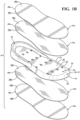
FIG. 1B is an exploded perspective view of the bladder ofFIG. 1A ; -
FIG. 1C is a perspective view showing the bladder ofFIG. 1A incorporated into an article of footwear; -
FIGS. 2A-2E are partial environmental views of a system and method for forming a configuration of a bladder in accordance with principles of the present disclosure; -
FIGS. 3A-3E are partial environmental views of a system and method for forming a configuration of a bladder in accordance with principles of the present disclosure; -
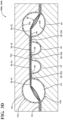
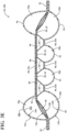
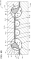
FIGS. 4A-4E are partial environmental views of a system and method for forming a configuration of a bladder in accordance with principles of the present disclosure; and -
FIGS. 5A-5E are partial environmental views of a system and method for forming a configuration of a bladder in accordance with principles of the present disclosure. - Corresponding reference numerals indicate corresponding parts throughout the drawings.
- Example configurations will now be described more fully with reference to the accompanying drawings. Example configurations are provided so that this disclosure will be thorough, and will fully convey the scope of the disclosure to those of ordinary skill in the art. Specific details are set forth such as examples of specific components, devices, and methods, to provide a thorough understanding of configurations of the present disclosure. It will be apparent to those of ordinary skill in the art that specific details need not be employed, that example configurations may be embodied in many different forms, and that the specific details and the example configurations should not be construed to limit the scope of the disclosure.
- The terminology used herein is for the purpose of describing particular exemplary configurations only and is not intended to be limiting. As used herein, the singular articles "a," "an," and "the" may be intended to include the plural forms as well, unless the context clearly indicates otherwise. The terms "comprises," "comprising," "including," and "having," are inclusive and therefore specify the presence of features, steps, operations, elements, and/or components, but do not preclude the presence or addition of one or more other features, steps, operations, elements, components, and/or groups thereof. The method steps, processes, and operations described herein are not to be construed as necessarily requiring their performance in the particular order discussed or illustrated, unless specifically identified as an order of performance. Additional or alternative steps may be employed.
- When an element or layer is referred to as being "on," "engaged to," "connected to," "attached to," or "coupled to" another element or layer, it may be directly on, engaged, connected, attached, or coupled to the other element or layer, or intervening elements or layers may be present. In contrast, when an element is referred to as being "directly on," "directly engaged to," "directly connected to," "directly attached to," or "directly coupled to" another element or layer, there may be no intervening elements or layers present. Other words used to describe the relationship between elements should be interpreted in a like fashion (e.g., "between" versus "directly between," "adjacent" versus "directly adjacent," etc.). As used herein, the term "and/or" includes any and all combinations of one or more of the associated listed items.
- The terms first, second, third, etc. may be used herein to describe various elements, components, regions, layers and/or sections. These elements, components, regions, layers and/or sections should not be limited by these terms. These terms may be only used to distinguish one element, component, region, layer or section from another region, layer or section. Terms such as "first," "second," and other numerical terms do not imply a sequence or order unless clearly indicated by the context. Thus, a first element, component, region, layer or section discussed below could be termed a second element, component, region, layer or section without departing from the teachings of the example configurations.
- In one configuration, a bladder for an article of footwear is provided and includes a plate, a first tensile layer disposed adjacent to a first side of the plate, and a second tensile layer disposed on an opposite side of the plate from the first tensile layer, the second tensile layer joined to the first tensile layer through the plate by a plurality of inner bonds. The bladder additionally includes a first barrier layer disposed adjacent to the first tensile layer and joined to the first tensile layer by a plurality of first outer bonds to form a first chamber, one or more of the first outer bonds interposed between adjacent ones of the inner bonds.
- The bladder may include one or more of the following optional features. For example, the first tensile layer and the second tensile layer may be formed of a first elastomeric material and the first barrier layer may be formed of a second elastomeric material different from the first elastomeric material. Additionally or alternatively, the first elastomeric material may have a lower melting temperature than the second elastomeric material.
- In one configuration, a second barrier layer may be disposed adjacent to the second tensile layer and may be joined to the second tensile layer by a plurality of second outer bonds to form a second chamber on the opposite side of the plate than the first chamber. In this configuration, the first chamber may be fluidly isolated from the second chamber by at least one of the first tensile layer and the second tensile layer. Additionally or alternatively, the first chamber may have a different pressure than the second chamber.
- The plate may include a plurality of apertures extending through the plate with each of the inner bonds being formed within one of the apertures.
- In one configuration, the second tensile layer may be joined to the first tensile layer around a periphery of the plate. Additionally or alternatively, the first tensile layer and the second tensile layer may be detached from the plate between the inner bonds to form one or more tensile elements. Further, each of the first outer bonds may be formed with one of the tensile elements.
- In another configuration, a bladder for an article of footwear is provided and includes a plate having one or more apertures, a first tensile layer disposed adjacent to a first side of the plate, a second tensile layer disposed on an opposite side of the plate from the first tensile layer and joined to the first tensile layer within each of the one or more apertures, and a first barrier layer disposed adjacent to the first tensile layer and joined to the first tensile layer at discrete locations to form a first chamber.
- The bladder may include one or more of the following optional features. For example, the first tensile layer and the second tensile layer may be formed of a first elastomeric material and the first barrier layer may be formed of a second elastomeric material different from the first elastomeric material. Additionally or alternatively, the first elastomeric material may have a lower melting temperature than the second elastomeric material.
- A second barrier layer may be disposed adjacent to the second tensile layer and may be joined to the second tensile layer by a plurality of second outer bonds to form a second chamber on the opposite side of the plate than the first chamber. The first chamber may be fluidly isolated from the second chamber by at least one of the first tensile layer and the second tensile layer. The first chamber may have a different pressure than the second chamber.
- In one configuration, the second tensile layer may be joined to the first tensile layer around a periphery of the plate. Additionally or alternatively, the first tensile layer and the second tensile layer may be detached from the plate between the apertures to form one or more tensile elements. In this configuration, the first barrier layer may be attached to each of the one or more tensile elements of the first tensile layer and/or may be attached to the first tensile layer along each of the apertures.
- Referring to
FIGS. 1A-1C , abladder 10 formed according to the principles of the present disclosure is shown. Generally, thebladder 10 includes afirst chamber 12a formed, at least in part, by a first pair ofbarrier layers bladder 10, and asecond chamber 12b formed, at least in part, by a second pair ofbarrier layers bladder 10 than thefirst chamber 12a. Particularly, thechambers plate 18, where inner barrier layers ortensile layers chamber plate 18, andouter barrier layers tensile layers chambers outer barrier layers tensile layer plate 18 from the respectiveouter barrier layer tensile layer plate 18 as the respectiveouter barrier layer - As illustrated in
FIG. 1C , thebladder 10 is formed as a full-length bladder 10 configured to extend continuously from an anterior end to a posterior end of an article offootwear 1000 having an upper 100 and anoutsole 200 attached to thebladder 10. As set forth below, thebladder 10 is illustrated with different configurations 10a-10d in each of atoe region 2, a ball region 3, amid-foot region 4, and aheel region 5. Particularly, theexample bladder 10 shows a first configuration 10a (FIGS. 2A-2E ) in thetoe region 2, a second configuration 10b (FIGS. 3A-3E ) in the ball region 3, a third configuration 10c (FIGS. 4A-4E ) in themid-foot region 4, and a fourth configuration 10d (FIGS. 5A-5E ) in theheel region 5. - While the configurations 10a-10d described in each of the
regions single bladder 10 in the manner shown and described herein, it will be appreciated that bladders manufactured according to the principles of the present disclosure can include any combination of one or more of the configurations shown inFIG. 1 . For example, an entire bladder may be formed using the configuration 10a shown and described inFIGS. 2A-2E , or of a combination of the configurations 10b, 10c shown and described inFIGS. 3A-3E andFIGS. 4A-4E . - Referring now to
FIG. 1B , the components of thebladder 10 are shown in an exploded view. As provided above, the bladder includes aplate 18, a pair oftensile layers plate 18, and a pair ofouter barrier layers tensile layers tensile layers plate 18 and a respective one of theouter barrier layers - With continued reference to
FIG. 1B , theplate 18 includes afirst side 20, asecond side 22 formed on an opposite side than thefirst side 20, and anouter periphery 24 extending between thefirst side 20 and thesecond side 22. A distance from thefirst side 20 to thesecond side 22 defines a thickness of theplate 18. Theplate 18 may be described as including a substantially planarinterior portion 26, and a peripheral portion 28 formed along theouter periphery 24 of theplate 18 and surrounding theinterior region 26. As shown, theplate 18 includes a plurality ofapertures 30 formed entirely through the thickness of theplate 18. Theapertures 30 may be formed through theinterior portion 26 and/or the peripheral portion 28. - In some configurations (10a, 10b), the thickness of the
plate 18 may be substantially constant, while in other configurations (10c, 10d), theplate 18 may have a variable thickness. Optionally, the peripheral portion 28 defines aperipheral flange 32 extending outwardly from theinterior portion 26 at an oblique angle relative to the interior portion 28. Additionally or alternatively, theinterior portion 26 and/or the peripheral portion 28 may includeprotuberances 34 formed on thefirst side 20 and/or thesecond side 22 to provide theplate 18 with a variable thickness. In the illustrated example, theplate 18 includes aprotuberance 34 formed as arib 34 extending from thefirst side 20 of theperipheral flange 32. However, in other examples, theplate 18 may include one or more projections formed in theinterior region 26 and/or on thesecond side 22. - The
plate 18 is formed, at least in part, by a material having a greater stiffness than the barrier layers 14a, 14b, 16a, 16b, and forms an internal structure or skeleton of thebladder 10. In some examples, theplate 18 includes one or more polymeric materials having a higher melting temperature than at least thetensile layers plate 18 may be formed of or include composite materials and/or metal materials. The first andsecond sides plate 18 are configured to inhibit bonding between theplate 18 and thetensile layers plate 18 itself may be formed of a material that is incompatible (i.e., resistant to bonding) with the material of thetensile layers sides plate 18 may be coated or covered with a bond inhibitor to prevent joining of thetensile layers plate 18. - With continued reference to
FIG. 1B , thetensile layers opposite sides plate 18 such that theplate 18 is interposed between thetensile layers bladder 10 is assembled. Thetensile layers inner surface outer surface tensile layer inner surface tensile layers outer periphery inner surface outer surface - When the
bladder 10 is assembled, theinner surfaces tensile layers plate 18 and are joined to each other byinner bonds 42 through one or more of theapertures 30 of theplate 18. Theinner surfaces plate 18, such that at least a portion of theplate 18 is enclosed between thetensile layers - Referring still to
FIG. 1B , theouter barrier layers opposite sides plate 18 and thetensile layers outer barrier layers outer barrier layers inner surface outer surface outer barrier layer inner surface outer barrier layers outer periphery inner surface outer surface - When the
bladder 10 is assembled, theinner surfaces outer barrier layers outer surfaces tensile layers inner surfaces outer barrier layers outer surfaces tensile layers bladder 10. For example, theinner surfaces outer barrier layers outer surfaces tensile layers interior portion 26 to form first andsecond web areas 52a, 52b of thebladder 10. Similarly, the outer peripheries of the barrier layers 14a, 14b, 16a, 16b may be joined together to form aperipheral seam 54 extending around thebladder 10 to seal the fluid (e.g., air) within the fluid-filledchamber chambers chambers bladder 10 where theinner surfaces outer barrier layers outer surfaces tensile layers surfaces tensile layers outer barrier layers interior void chambers - The barrier layers 14a, 14b, 16a, 16b can each be produced from an elastomeric material that includes one or more thermoplastic polymers and/or one or more cross-linkable polymers. In an aspect, the elastomeric material can include one or more thermoplastic elastomeric materials, such as one or more thermoplastic polyurethane (TPU) copolymers, one or more ethylene-vinyl alcohol (EVOH) copolymers, and the like. The
tensile layers outer barrier layers - The first elastomeric material is selected with a first melting temperature suitable for allowing the
tensile layers plate 18 without affecting the material properties of theplate 18. For instance, the first melting temperature of the first elastomeric material is low enough that theplate 18 will not be melted, deformed, or weakened when subjected to the first melting temperature during assembly of thebladder 10. Accordingly, elastomeric material having different melting temperatures can be selected as thetensile layer plate 18 is formed of a polymeric material having a relatively low melting point (compared to metals or composites), the first elastomeric material may be a low-melt TPU having a melting temperature that is less than a melting temperature of the material of theplate 18. - The second elastomeric material of the
outer barrier layers tensile layers outer barrier layers chambers - One or more of the barrier layers 14a, 14b, 16a, 16b can independently be transparent, translucent, and/or opaque. As used herein, the term "transparent" for a barrier layer and/or a fluid-filled chamber means that light passes through the barrier layer in substantially straight lines and a viewer can see through the barrier layer. In comparison, for an opaque barrier layer, light does not pass through the barrier layer and one cannot see clearly through the barrier layer at all. A translucent barrier layer falls between a transparent barrier layer and an opaque barrier layer, in that light passes through a translucent layer but some of the light is scattered so that a viewer cannot see clearly through the layer.
- As used herein, the term "barrier layer" (e.g.,
barrier layers - As used herein, "polyurethane" refers to a copolymer (including oligomers) that contains a urethane group (-N(C=O)O-). These polyurethanes can contain additional groups such as ester, ether, urea, allophanate, biuret, carbodiimide, oxazolidinyl, isocynaurate, uretdione, carbonate, and the like, in addition to urethane groups. In an aspect, one or more of the polyurethanes can be produced by polymerizing one or more isocyanates with one or more polyols to produce copolymer chains having (-N(C=O)O-) linkages.
- Examples of suitable isocyanates for producing the polyurethane copolymer chains include diisocyanates, such as aromatic diisocyanates, aliphatic diisocyanates, and combinations thereof. Examples of suitable aromatic diisocyanates include toluene diisocyanate (TDI), TDI adducts with trimethyloylpropane (TMP), methylene diphenyl diisocyanate (MDI), xylene diisocyanate (XDI), tetramethylxylylene diisocyanate (TMXDI), hydrogenated xylene diisocyanate (HXDI), naphthalene 1,5-diisocyanate (NDI), 1,5-tetrahydronaphthalene diisocyanate, para-phenylene diisocyanate (PPDI), 3,3' - dimethyldipheny1-4, 4' -diisocyanate (DDDI), 4,4 '-dibenzyl diisocyanate (DBDI), 4-chloro-1,3-phenylene diisocyanate, and combinations thereof. In some embodiments, the copolymer chains are substantially free of aromatic groups.
- In particular aspects, the polyurethane polymer chains are produced from diisocynates including HMDI, TDI, MDI, H12 aliphatics, and combinations thereof. In an aspect, the thermoplastic TPU can include polyester-based TPU, polyether-based TPU, polycaprolactone-based TPU, polycarbonate-based TPU, polysiloxane-based TPU, or combinations thereof.
- In another aspect, the polymeric layer can be formed of one or more of the following: EVOH copolymers, poly(vinyl chloride), polyvinylidene polymers and copolymers (e.g., polyvinylidene chloride), polyamides (e.g., amorphous polyamides), amide-based copolymers, acrylonitrile polymers (e.g., acrylonitrile-methyl acrylate copolymers), polyethylene terephthalate, polyether imides, polyacrylic imides, and other polymeric materials known to have relatively low gas transmission rates. Blends of these materials, as well as with the TPU copolymers described herein and optionally including combinations of polyimides and crystalline polymers, are also suitable.
- The barrier layers 14a, 14b, 16a, 16b may include two or more sublayers (multilayer film) such as shown in
Mitchell et al., U.S. Patent No. 5,713,141 andMitchell et al., U.S. Patent No. 5,952,065 , the disclosures of which are incorporated by reference in their entirety. In embodiments where the barrier layers 14a, 14b, 16a, 16b include two or more sublayers, examples of suitable multilayer films include microlayer films, such as those disclosed inBonk et al., U.S. Patent No. 6,582,786 , which is incorporated by reference in its entirety. In further embodiments, the barrier layers 14a, 14b, 16a, 16b may each independently include alternating sublayers of one or more TPU copolymer materials and one or more EVOH copolymer materials, where the total number of sublayers in each of the barrier layers 14a, 14b, 16a, 16b includes at least four (4) sublayers, at least ten (10) sublayers, at least twenty (20) sublayers, at least forty (40) sublayers, and/or at least sixty (60) sublayers. - The
bladder 10 can be produced from the barrier layers 14a, 14b, 16a, 16b using any suitable technique, such as thermoforming (e.g. vacuum thermoforming), blow molding, extrusion, injection molding, vacuum molding, rotary molding, transfer molding, pressure forming, heat sealing, casting, low-pressure casting, spin casting, reaction injection molding, radio frequency (RF) welding, and the like. In an aspect, the barrier layers 14a, 14b, 16a, 16b can be produced by co-extrusion followed by vacuum thermoforming to produce aninflatable chamber chamber - The
chambers chambers chambers chambers chambers chambers chambers - The
chambers chambers chambers barrier layers - Turning now to
FIGS. 2A-5E ,systems 100a-100d and methods for forming the different configurations 10a-10d of thebladder 10 are shown. As discussed above, the different configurations 10a-10d are illustrated in distinct regions 2-5 of asingle bladder 10. However, one or more of the configurations 10a-10d may be utilized in any region of thebladder 10, and/or theentire bladder 10 may be formed using a single one of the configurations 10a-10d. - With reference to
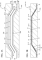
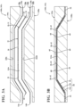
FIGS. 2A-2E , asystem 100a and method for forming the first configuration 10a of thebladder 10 are shown. As, shown, the system includes afirst tool 102a (FIGS. 2A and 2B ) and asecond tool 104a (FIGS. 2C and2D ). Thefirst tool 102a includes anupper mold 106a and alower mold 108a each including arespective mold surface lower mold surfaces mold cavity 114a for receiving each of thetensile layers plate 18. Accordingly, profiles of themold surfaces second sides plate 18. As illustrated inFIG. 2A , theplate 18 and thetensile layers mold cavity 114a in a layered arrangement with theplate 18 disposed between thetensile layers - With the
components mold cavity 114a, thefirst tool 102a is then moved to a closed position (FIG. 2B ) to join theinner surfaces tensile layer 14a and the secondtensile layer 14b together through and around theplate 18. Particularly, theinner surfaces tensile layers apertures 30 of theplate 18 at respectiveinner bonds 42. Similarly, theouter peripheries tensile layers outer periphery 24 of theplate 18 to form a first portion of theperipheral seam 54. Here, theplate 18 is at least partially encapsulated within the joinedtensile layers components chassis 58 for incorporation within thebladder 10. - The
first tool 102a may be athermoforming tool 102a configured to subject thecomponents tensile layers tensile layers sides plate 18 are inhibited from bonding to thetensile layers plate 18 of an incompatible material or by coating thesides plate 18 may have a higher melting temperature than thetensile layers plate 18 and thetensile layers tensile layers tensile layers plate 18 during the second step (FIG. 2B ), thetensile layers plate 18 at areas between theinner bonds 42 and theperipheral seam 54. - Turning now to
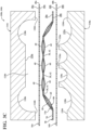
FIG. 2C , thechassis 58 is shown after removal from thefirst tool 102a. Here, thetensile layers plate 18, and are detached from theplate 18 between theinner bonds 42 and theperipheral seam 54. These detached portions of thetensile layers tensile elements 60 of thechassis 58, which, as described below, are ultimately attached to theouter barrier layers outer barrier layers chassis 58. - At
FIG. 2C , thechassis 58 and theouter barrier layers second tool 104a. Thesecond tool 104a includes anupper mold 116a and alower mold 118a each including arespective mold surface lower mold surfaces outer barrier layers chassis 58. As illustrated inFIG. 2C , theplate 18 and theouter barrier layers chassis 58 disposed between theouter barrier layers - The profiles of the
mold surfaces second tool 104a respectively define the shapes of the first andsecond chambers bladder 10. For instance, themold surfaces interior projections 126a corresponding to theweb areas 52a, 52b andperipheral projections 126b corresponding to theperipheral seam 54. Theinterior projections 126a of eachmold surface tensile elements 60 of thechassis 58, between theinner bonds 42. Thus, as discussed below, theinterior projections 126a are configured to compress theouter barrier layers tensile elements 60 formed by thetensile layers peripheral projections 126b are positioned outwardly from theouter periphery 24 of theplate 18, and are configured to compress theouter peripheries outer layers peripheral seam 54 formed by thetensile layers - The
mold surfaces recesses projections chambers lower mold surfaces interior recesses 128a corresponding tointerior subchambers 62 andperipheral recesses 128b corresponding toperipheral subchambers 64. Here, theinterior recesses 126a of theupper mold 116a are shallower than theinterior recesses 126a of thelower mold 118a, whereby theinterior recesses 126a of theupper mold 116a forminterior subchambers 62 in thefirst chamber 12a that have a lesser height than theinterior subchambers 62 of thesecond chamber 12b. - Turning now to
FIG. 2D , with theouter barrier layers chassis 58 positioned within the mold cavity 124a, thesecond tool 104a is moved to the closed position. Thesecond tool 104a may be configured as avacuum forming tool 104a, which imparts a vacuum within the mold cavity 124a to draw each of theouter barrier layers respective mold surface chamber - In the closed position, the
interior projections 126a and theperipheral projections 126b of eachmold chassis 58, such that the barrier layers 16a, 16b and thechassis 58 are compressed between opposing (i.e., facing) distal ends of correspondingprojections interior projections 126a of eachmold tensile elements 60 of thechassis 58 to form a first plurality of the outer bonds 50 between the firstinterior barrier layer 14a and the firstouter barrier layer 16a on thefirst side 20 of theplate 18, and a second plurality of the outer bonds 50 between the secondtensile layer 14b and the secondouter barrier layer 16b on thesecond side 22 of theplate 18. Theperipheral projections 126b are aligned with each other across the portion of theperipheral seam 54 formed by thetensile layers outer barrier layers tensile layers outer barrier layers peripheral seam 54. - With the
outer barrier layers tensile layers peripheral seam 54, thebladder 10 can be removed from thesecond tool 104a, as shown inFIG. 2E . Optionally, theinterior voids first chamber 12a and thesecond chamber 12b may be pressurized prior to or following removal of thebladder 10 from thesecond tool 104a. As a reminder, theinterior voids tensile layers outer barrier layers outer barrier layers peripheral seam 54 are biased apart from the respectivetensile layers interior voids - As shown and discussed above, the different profiles imparted to the
outer barrier layers first chamber 12a and thesecond chamber 12b having different profiles. Additionally, theinterior voids chambers interior void 56a of thefirst chamber 12a may have a greater pressure than theinterior void 56b of thesecond chamber 12b, or vice versa. Optionally,spaces 66 formed between thetensile elements 60 and theplate 18 may also be pressurized with same or different pressures than the pressures of theinterior voids - With particular reference to
FIGS. 3A-3E , asystem 100b and method for forming the second configuration 10b of thebladder 10 are shown. In view of the substantial similarity in structure and function of the components associated with thesystem 100a and configuration 10a with respect to thesystem 100b and configuration 10b, like reference numerals are used hereinafter and in the drawings to identify like components while like reference numerals containing letter extensions are used to identify those components that have been modified. - As shown in
FIGS. 3A and 3B , formation of the second configuration 10b of thebladder 10 includes initially forming thechassis 58 using thefirst tool 102a in the same manner as described above with respect toFIGS. 2A and 2B . Thechassis 58 and theouter barrier layers second tool 104b for forming thebladder 10, as shown inFIG. 3C . Here, thesecond tool 104b is substantially similar to thesecond tool 104a described above, except that theupper mold surface 120b of theupper mold 116b has a topography corresponding to a topography of thefirst side 20 of theinterior portion 26 of theplate 18. Thus, theupper mold surface 120b is generally configured to compress the firstouter barrier layer 16a and the firsttensile layer 14a together against thefirst side 20 of theplate 18 and between theinner bonds 42. In this particular example, each of thefirst side 22 of theplate 18 and theupper mold surface 120b are shown as being planar. Accordingly, the planarupper mold surface 120b compresses the firstouter barrier layer 16a and the firsttensile layer 14a together against the planarinterior portion 26 of theplate 18. However, in other examples, theinterior portion 26 of theplate 18 may be contoured, and theupper mold surface 120b may have a corresponding or complementary contour. - Referring to
FIG. 3D , when thesystem 100b is moved to the closed position, the planar portion of theupper mold surface 120b compresses the firstouter barrier layer 16a against the firsttensile layer 14a across theinterior portion 26 of theplate 18 and the firstouter barrier layer 16a is joined to the firsttensile layer 14a in the compressed areas. Accordingly, not only is the firstouter barrier layer 16a joined to the firsttensile layer 14a along thetensile elements 60, but the barrier layers 14a, 16a are also joined together across thefirst bonds 42 between thetensile layers web area 52a offirst chamber 12a extends continuously across at least one of theinner bonds 42, as opposed to only extending between theinner bonds 42, as was done in the first configuration. In the illustrated example, theweb area 52a of thefirst chamber 12a is shown as extending across two of theinner bonds 42. - Turning to
FIG. 3E , when thefirst chamber 12a is inflated, no interior subchambers are formed in thefirst chamber 12a, as the firstouter barrier layer 16a is continuously joined to the firsttensile layer 14a along theinterior portion 26 of theplate 18. As shown, thefirst chamber 12a only includes theperipheral subchambers 64. Here, thesecond chamber 12b is formed the same as described above with respect to the first configuration 10a, and includes interior subchambers 62 and theperipheral subchambers 64. Again, thefirst chamber 12a and thesecond chamber 12b may have the same or different pressures. - With particular reference to
FIGS. 4A-4E , asystem 100c and method for forming the third configuration 10c of thebladder 10 are shown. In view of the substantial similarity in structure and function of the components associated with thesystem 100a and configuration 10a with respect to thesystem 100c and configuration 10c, like reference numerals are used hereinafter and in the drawings to identify like components while like reference numerals containing letter extensions are used to identify those components that have been modified. - As shown in
FIG. 4A , in the third configuration 10c, theplate 18 includes aprotuberance 34 formed along theflange 32 on thefirst side 20 of theplate 18. As discussed in greater detail below and shown inFIGS. 4A and4D , the height of theprotuberance 34 in the third configuration corresponds to a height of theperipheral subchambers 64 of thefirst chamber 12a. Accordingly, when thebladder 10 is formed, theprotuberance 34 will support theinner surface 44a of the firstouter barrier layer 16a within theperipheral subchamber 64, but will not impart a profile or deformation to the firstouter barrier layer 16a when thebladder 10 is in a resting state (e.g., unaffected by external forces). - In
FIG 4B , thechassis 58 is formed for the third configuration 10c. Here, thechassis 58 is formed using afirst tool 102c in the same manner as discussed above with respect to the first configuration 10a, except theupper mold surface 110c of theupper mold 106c has a profile corresponding to the profile of thefirst side 20 of theplate 18 in the third configuration 10c. Accordingly, theupper mold surface 110c hasrecesses 130c corresponding to the profile of theprotuberances 34. Here, theupper mold surface 110c and thelower mold surface 112a define amold cavity 114c corresponding to the profile of the fourth configuration 10d. When thechassis 58 is formed, the firsttensile layer 14a conforms to the shape of theprotuberances 34. - Referring to
FIGS. 4C and4D , because theprotuberances 34 are configured to be confined within the profile of theperipheral subchambers 64, the third configuration 10c of thebladder 10 can be formed using either one of thesecond tools bladder 10. In the illustrated example, thesecond tool 104b is configured for forming thecontinuous web area 52a in thefirst chamber 12a. However, the third configuration 10c may also be formed withinterior subchambers 62. - With continued reference to
FIG. 4D , when thesystem 100c is closed, theprotuberance 34 and the firsttensile layer 14a are contained within the portion of theperipheral subchamber 64. In the illustrated example, theouter surface 38a of the firsttensile layer 14a is held in contact with theinner surface 44a of the firstouter barrier layer 16a by theprotuberance 34. Optionally, the firsttensile layer 14a may be joined to the firstouter barrier layer 16a at one or more points along theprotuberance 34 within theperipheral subchamber 64. Providing theprotuberance 34 within theperipheral subchamber 64 serves to provide additional structural support to thebladder 10 around the outer periphery of the foot. However, similar concepts may be utilized in other regions of thebladder 10. For example, theplate 18 may include protuberances extending into any one of theinterior chambers 62 orperipheral chambers 64 of the first and/orsecond chamber - With particular reference to
FIGS. 5A-5E , asystem 100d and method for forming the fourth configuration 10d of thebladder 10 are shown. In view of the substantial similarity in structure and function of the components associated with thesystem 100a and configuration 10a with respect to thesystem 100d and configuration 10d, like reference numerals are used hereinafter and in the drawings to identify like components while like reference numerals containing letter extensions are used to identify those components that have been modified. - The
system 100d and method ofFIGS. 5A-5E are substantially similar to those described above with respect toFIGS. 4A-4E , where theplate 18 includes theprotuberance 34 extending from thefirst side 20 of theflange 32. However, as best shown inFIGS. 5C and5D , theprotuberance 34 has a height that protrudes beyond the firstouter barrier layer 16a such that a portion of the firstouter barrier layer 16a conforms to theprotuberance 34 and forms aprotrusion 68 extending from theperipheral chamber 64. Accordingly, thesystem 100d is provided with afirst tool 102d and asecond tool 104d configured to accommodate the increased height of theprotuberance 34. For instance, the upper mold 106d of thefirst tool 102d is formed with anupper mold surface 110d including recesses 130d having a greater height or depth than therecesses 130d of theupper mold 106c described above. Likewise, theupper mold surface 120d of theupper mold 116d of thesecond tool 104d includes indentations 132c formed in theperipheral recesses 128b for accommodating theextended protuberances 34. Accordingly, each of thefirst tool 102d and thesecond tool 104d definerespective mold cavities - Thus, in contrast to the first and second configurations 10a, 10b where the
peripheral subchamber 64 is entirely filled with fluid, and the third configuration 10c where theprotuberance 34 is contained within the natural profile of theperipheral chamber 64, in the fourth configuration 10d, theprotuberance 34 imparts an extended profile to theperipheral subchamber 64. Again, while the illustrated example shows theprotuberance 34 disposed in the peripheral portion 28 of theplate 18, theplate 18 may additionally or alternatively include projections formed in the interior portion 28 on eitherside - The
systems 100a-100d and methods for forming the different configurations 10a-10d of thebladder 10 described above provide several advantages. Initially, providing theplate 18 within thebladder 10 allows an overall stiffness of thebladder 10 to be tuned. For instance, plates formed of different materials, shapes, and thicknesses may be incorporated within the bladder to provide thebladder 10 with integrated stiffness and support. In addition to providing structural benefits, theplate 18 simplifies formation of thebladder 10 by definingbonding locations 42 for thetensile layers tensile elements 60 used to constrain expansion of theouter barrier layers - Here, the use of
tensile layers plate 18 allows thetensile layers plate 18 in a single molding step without affecting the properties of theplate 18. Thesetensile layers tensile layers tensile elements 60 are simply formed by attaching thetensile layers tensile layers first chamber 12a and thesecond chamber 12b, such that thefirst chamber 12a can be pressurized with a different pressure than thesecond chamber 12b. Accordingly, thebarrier 10 may be tuned with first andsecond chambers - The following Clauses provide an exemplary configuration for a bladder for an article of footwear described above.
- Clause 1: A bladder for an article of footwear, the bladder comprising a plate, a first tensile layer disposed adjacent to a first side of the plate, a second tensile layer disposed on an opposite side of the plate from the first tensile layer, the second tensile layer joined to the first tensile layer through the plate by a plurality of inner bonds, and a first barrier layer disposed adjacent to the first tensile layer and joined to the first tensile layer by a plurality of first outer bonds to form a first chamber, one or more of the first outer bonds interposed between adjacent ones of the inner bonds.
- Clause 2: The bladder of Clause 1, wherein the first tensile layer and the second tensile layer are formed of a first elastomeric material and the first barrier layer is formed of a second elastomeric material different from the first elastomeric material.
- Clause 3: The bladder of
Clause 2, wherein the first elastomeric material has a lower melting temperature than the second elastomeric material. - Clause 4: The bladder of any of the preceding Clauses, further comprising a second barrier layer disposed adjacent to the second tensile layer and joined to the second tensile layer by a plurality of second outer bonds to form a second chamber on the opposite side of the plate than the first chamber.
- Clause 5: The bladder of
Clause 4, wherein the first chamber is fluidly isolated from the second chamber by at least one of the first tensile layer and the second tensile layer. - Clause 6: The bladder of
Clause 4, wherein the first chamber has a different pressure than the second chamber. - Clause 7: The bladder of any of the preceding Clauses, wherein the plate includes a plurality of apertures extending through the plate and each of the inner bonds is formed within one of the apertures.
- Clause 8: The bladder of any of the preceding Clauses, wherein the second tensile layer is joined to the first tensile layer around a periphery of the plate.
- Clause 9: The bladder of any of the preceding Clauses, wherein the first tensile layer and the second tensile layer are detached from the plate between the inner bonds to form one or more tensile elements.
- Clause 10: The bladder of Clause 9, wherein each of the first outer bonds is formed with one of the tensile elements.
- Clause 11: A bladder for an article of footwear, the bladder comprising a plate having one or more apertures, a first tensile layer disposed adjacent to a first side of the plate, a second tensile layer disposed on an opposite side of the plate from the first tensile layer and joined to the first tensile layer within each of the one or more apertures, and a first barrier layer disposed adjacent to the first tensile layer and joined to the first tensile layer at discrete locations to form a first chamber.
- Clause 12: The bladder of Clause 11, wherein the first tensile layer and the second tensile layer are formed of a first elastomeric material and the first barrier layer is formed of a second elastomeric material different from the first elastomeric material.
- Clause 13: The bladder of Clause 12, wherein the first elastomeric material has a lower melting temperature than the second elastomeric material.
- Clause 14: The bladder of any of the preceding Clauses, further comprising a second barrier layer disposed adjacent to the second tensile layer and joined to the second tensile layer by a plurality of second outer bonds to form a second chamber on the opposite side of the plate than the first chamber.
- Clause 15: The bladder of Clause 14, wherein the first chamber is fluidly isolated from the second chamber by at least one of the first tensile layer and the second tensile layer.
- Clause 16: The bladder of Clause 14, wherein the first chamber has a different pressure than the second chamber.
- Clause 17: The bladder of any of the preceding Clauses, wherein the second tensile layer is joined to the first tensile layer around a periphery of the plate.
- Clause 18: The bladder of any of the preceding Clauses, wherein the first tensile layer and the second tensile layer are detached from the plate between the apertures to form one or more tensile elements.
- Clause 19: The bladder of
Clause 18, wherein the first barrier layer is attached to each of the one or more tensile elements of the first tensile layer. - Clause 20: The bladder of
Clause 18, wherein the first barrier layer is attached to the first tensile layer along each of the apertures. - The foregoing description has been provided for purposes of illustration and description. It is not intended to be exhaustive or to limit the disclosure. Individual elements or features of a particular configuration are generally not limited to that particular configuration, but, where applicable, are interchangeable and can be used in a selected configuration, even if not specifically shown or described. The same may also be varied in many ways. Such variations are not to be regarded as a departure from the disclosure, and all such modifications are intended to be included within the scope of the disclosure.
Claims (15)
- A bladder for an article of footwear, the bladder comprising:a plate having a variable thickness;a first tensile layer disposed adjacent to a first side of the plate;a second tensile layer disposed on an opposite side of the plate from the first tensile layer, the second tensile layer bonded to the first tensile layer through the plate by a plurality of distinct inner bonds; anda first barrier layer disposed adjacent to the first tensile layer and joined to the first tensile layer by a plurality of first outer bonds to form a first chamber, one or more of the first outer bonds interposed between adjacent ones of the inner bonds.
- The bladder of Claim 1, wherein the first tensile layer is formed of a first elastomeric material.
- The bladder of Claim 1 or Claim 2, wherein the second tensile layer is formed of a second elastomeric material.
- The bladder of Claim 3, wherein the first elastomeric material and the second elastomeric material are different than a material forming the first barrier layer.
- The bladder of Claim 3 or Claim 4, wherein the first elastomeric material and the second elastomeric material have a lower melting temperature than a material forming the first barrier layer.
- The bladder of Claim 1, further comprising a second barrier layer disposed adjacent to the second tensile layer and joined to the second tensile layer by a plurality of second outer bonds to form a second chamber on the opposite side of the plate than the first chamber.
- The bladder of Claim 6, wherein the first chamber is fluidly isolated from the second chamber by at least one of the first tensile layer and the second tensile layer.
- The bladder of Claim 6, wherein the first chamber has a different pressure than the second chamber.
- The bladder of Claim 1, wherein the plate includes a plurality of apertures extending through the plate and each of the inner bonds is formed within one of the apertures.
- The bladder of Claim 1, wherein the second tensile layer is joined to the first tensile layer around a periphery of the plate.
- The bladder of Claim 1, wherein the first tensile layer and the second tensile layer are detached from the plate between the inner bonds to form one or more tensile elements.
- The bladder of Claim 1, wherein the plate includes at least one protrusion.
- The bladder of Claim 12, wherein the at least one protrusion is located at an outer periphery of the plate.
- The bladder of Claim 12 or Claim 13, wherein the protrusion is covered by one of the first tensile layer and the second tensile layer.
- An article of footwear incorporating the bladder of any of the foregoing claims.
Applications Claiming Priority (4)
| Application Number | Priority Date | Filing Date | Title |
|---|---|---|---|
| US202063023271P | 2020-05-12 | 2020-05-12 | |
| US17/317,793 US11918074B2 (en) | 2020-05-12 | 2021-05-11 | Bladder for article of footwear |
| PCT/US2021/031946 WO2021231540A1 (en) | 2020-05-12 | 2021-05-12 | Bladder for article of footwear |
| EP21730033.4A EP4149312B1 (en) | 2020-05-12 | 2021-05-12 | Bladder for article of footwear |
Related Parent Applications (1)
| Application Number | Title | Priority Date | Filing Date |
|---|---|---|---|
| EP21730033.4A Division EP4149312B1 (en) | 2020-05-12 | 2021-05-12 | Bladder for article of footwear |
Publications (2)
| Publication Number | Publication Date |
|---|---|
| EP4529800A2 true EP4529800A2 (en) | 2025-04-02 |
| EP4529800A3 EP4529800A3 (en) | 2025-05-21 |
Family
ID=78513434
Family Applications (2)
| Application Number | Title | Priority Date | Filing Date |
|---|---|---|---|
| EP25156863.0A Pending EP4529800A3 (en) | 2020-05-12 | 2021-05-12 | Bladder for article of footwear |
| EP21730033.4A Active EP4149312B1 (en) | 2020-05-12 | 2021-05-12 | Bladder for article of footwear |
Family Applications After (1)
| Application Number | Title | Priority Date | Filing Date |
|---|---|---|---|
| EP21730033.4A Active EP4149312B1 (en) | 2020-05-12 | 2021-05-12 | Bladder for article of footwear |
Country Status (4)
| Country | Link |
|---|---|
| US (3) | US11918074B2 (en) |
| EP (2) | EP4529800A3 (en) |
| CN (1) | CN115697123B (en) |
| WO (1) | WO2021231540A1 (en) |
Families Citing this family (8)
| Publication number | Priority date | Publication date | Assignee | Title |
|---|---|---|---|---|
| US20220225731A1 (en) * | 2020-08-03 | 2022-07-21 | Hafia Salum Mkumba | Footwear midsole comprising a support and one or more internal bladders |
| US12648618B2 (en) | 2022-05-11 | 2026-06-09 | Nike, Inc. | Footwear with fiber-reinforced fluid-filled bladder |
| US12490807B2 (en) * | 2022-06-16 | 2025-12-09 | Nike, Inc. | Bladder for an article of footwear |
| EP4539695A1 (en) * | 2022-06-16 | 2025-04-23 | NIKE Innovate C.V. | Bladder for an article of footwear |
| US12302980B2 (en) * | 2023-05-31 | 2025-05-20 | Wolverine Outdoors, Inc. | Footwear sole and related method of use |
| US12604945B2 (en) | 2023-06-15 | 2026-04-21 | Nike, Inc. | Bladder for an article of footwear |
| US12611005B2 (en) * | 2023-12-15 | 2026-04-28 | Nike, Inc. | Cushioning component for a wearable article |
| US20250194743A1 (en) * | 2023-12-15 | 2025-06-19 | Nike, Inc. | Cushioning component for a wearable article and method of manufacturing same |
Citations (2)
| Publication number | Priority date | Publication date | Assignee | Title |
|---|---|---|---|---|
| US5713141A (en) | 1994-08-31 | 1998-02-03 | Nike, Inc. | Cushioning device with improved flexible barrier membrane |
| US6582786B1 (en) | 1998-09-11 | 2003-06-24 | Nike, Inc. | Flexible membranes |
Family Cites Families (22)
| Publication number | Priority date | Publication date | Assignee | Title |
|---|---|---|---|---|
| US1504908A (en) * | 1923-01-03 | 1924-08-12 | Sato Ryuji | Insole for shoes |
| US2677906A (en) | 1952-08-14 | 1954-05-11 | Reed Arnold | Cushioned inner sole for shoes and meth od of making the same |
| CA1338369C (en) * | 1988-02-24 | 1996-06-11 | Jean-Pierre Vermeulen | Shock absorbing system for footwear application |
| JPH05503865A (en) | 1990-02-16 | 1993-06-24 | トレトルン アクティエボラーグ | stability shoe device |
| US5718063A (en) | 1995-07-17 | 1998-02-17 | Asics Corporation | Midsole cushioning system |
| US5918383A (en) | 1995-10-16 | 1999-07-06 | Fila U.S.A., Inc. | Sports shoe having an elastic insert |
| US6571490B2 (en) | 2000-03-16 | 2003-06-03 | Nike, Inc. | Bladder with multi-stage regionalized cushioning |
| US6402879B1 (en) * | 2000-03-16 | 2002-06-11 | Nike, Inc. | Method of making bladder with inverted edge seam |
| US6971193B1 (en) | 2002-03-06 | 2005-12-06 | Nike, Inc. | Bladder with high pressure replenishment reservoir |
| WO2007146958A2 (en) | 2006-06-12 | 2007-12-21 | Hardy Alan H | Cushioning system for footwear |
| KR100741628B1 (en) | 2007-02-07 | 2007-07-23 | 양희운 | Impact of shock-absorbing shoes of circular air |
| US8991072B2 (en) * | 2010-02-22 | 2015-03-31 | Nike, Inc. | Fluid-filled chamber incorporating a flexible plate |
| US9603414B2 (en) | 2013-03-15 | 2017-03-28 | Nike, Inc. | Fluid-filled chamber with a tensile element |
| US9730487B2 (en) * | 2013-07-12 | 2017-08-15 | Nike, Inc. | Contoured fluid-filled chamber |
| EP3280288B1 (en) * | 2015-04-08 | 2019-06-05 | NIKE Innovate C.V. | Article with a cushioning assembly having inner and outer bladder elements and a reinforcement element and method of manufacturing an article |
| CN107405851B (en) | 2015-04-21 | 2019-10-22 | 耐克创新有限合伙公司 | Capsule-like element formed from three sheets and method of making a pouch-like element |
| US10512301B2 (en) | 2015-08-06 | 2019-12-24 | Nike, Inc. | Cushioning assembly for an article of footwear |
| EP3624628B1 (en) * | 2017-05-18 | 2022-11-23 | Nike Innovate C.V. | Cushioning article with tensile component and method of manufacturing a cushioning article |
| WO2018217559A1 (en) | 2017-05-23 | 2018-11-29 | Nike, Inc. | Midsole system with graded response |
| KR102326973B1 (en) * | 2017-05-23 | 2021-11-16 | 나이키 이노베이트 씨.브이. | Midsole with graded response |
| WO2018217557A2 (en) | 2017-05-23 | 2018-11-29 | Nike, Inc. | Domed midsole with staged compressive stiffness |
| US11871812B2 (en) * | 2020-10-30 | 2024-01-16 | Nike, Inc. | Cushioning element for article of footwear |
-
2021
- 2021-05-11 US US17/317,793 patent/US11918074B2/en active Active
- 2021-05-12 EP EP25156863.0A patent/EP4529800A3/en active Pending
- 2021-05-12 WO PCT/US2021/031946 patent/WO2021231540A1/en not_active Ceased
- 2021-05-12 CN CN202180042477.4A patent/CN115697123B/en active Active
- 2021-05-12 EP EP21730033.4A patent/EP4149312B1/en active Active
-
2024
- 2024-01-24 US US18/421,515 patent/US12262782B2/en active Active
-
2025
- 2025-02-27 US US19/065,814 patent/US12648617B2/en active Active
Patent Citations (3)
| Publication number | Priority date | Publication date | Assignee | Title |
|---|---|---|---|---|
| US5713141A (en) | 1994-08-31 | 1998-02-03 | Nike, Inc. | Cushioning device with improved flexible barrier membrane |
| US5952065A (en) | 1994-08-31 | 1999-09-14 | Nike, Inc. | Cushioning device with improved flexible barrier membrane |
| US6582786B1 (en) | 1998-09-11 | 2003-06-24 | Nike, Inc. | Flexible membranes |
Also Published As
| Publication number | Publication date |
|---|---|
| EP4149312A1 (en) | 2023-03-22 |
| US20210353001A1 (en) | 2021-11-18 |
| US12648617B2 (en) | 2026-06-09 |
| US20250194742A1 (en) | 2025-06-19 |
| US20240156211A1 (en) | 2024-05-16 |
| EP4529800A3 (en) | 2025-05-21 |
| US12262782B2 (en) | 2025-04-01 |
| US11918074B2 (en) | 2024-03-05 |
| EP4149312B1 (en) | 2025-02-12 |
| WO2021231540A1 (en) | 2021-11-18 |
| CN115697123B (en) | 2026-07-14 |
| CN115697123A (en) | 2023-02-03 |
Similar Documents
| Publication | Publication Date | Title |
|---|---|---|
| EP4149312B1 (en) | Bladder for article of footwear | |
| US12317952B2 (en) | Bladder and sole structure for article of footwear | |
| US20250331606A1 (en) | Sole structure for article of footwear | |
| US11839262B2 (en) | Upper for article of footwear | |
| US11440237B2 (en) | Method and system for forming a bladder | |
| US20250160481A1 (en) | Cushioning element for article of footwear | |
| WO2021247337A1 (en) | Sole structure for article of footwear | |
| EP4723917A1 (en) | Bladder for article of footwear or apparel | |
| WO2024254275A1 (en) | Bladder for article of footwear or apparel | |
| WO2025035064A1 (en) | Sole structure for article of footwear |
Legal Events
| Date | Code | Title | Description |
|---|---|---|---|
| PUAI | Public reference made under article 153(3) epc to a published international application that has entered the european phase |
Free format text: ORIGINAL CODE: 0009012 |
|
| STAA | Information on the status of an ep patent application or granted ep patent |
Free format text: STATUS: THE APPLICATION HAS BEEN PUBLISHED |
|
| AC | Divisional application: reference to earlier application |
Ref document number: 4149312 Country of ref document: EP Kind code of ref document: P |
|
| AK | Designated contracting states |
Kind code of ref document: A2 Designated state(s): AL AT BE BG CH CY CZ DE DK EE ES FI FR GB GR HR HU IE IS IT LI LT LU LV MC MK MT NL NO PL PT RO RS SE SI SK SM TR |
|
| REG | Reference to a national code |
Ref country code: DE Ref legal event code: R079 Free format text: PREVIOUS MAIN CLASS: A43B0013200000 Ipc: A43B0013120000 |
|
| PUAL | Search report despatched |
Free format text: ORIGINAL CODE: 0009013 |
|
| AK | Designated contracting states |
Kind code of ref document: A3 Designated state(s): AL AT BE BG CH CY CZ DE DK EE ES FI FR GB GR HR HU IE IS IT LI LT LU LV MC MK MT NL NO PL PT RO RS SE SI SK SM TR |
|
| RIC1 | Information provided on ipc code assigned before grant |
Ipc: A43B 13/20 20060101ALI20250417BHEP Ipc: A43B 13/18 20060101ALI20250417BHEP Ipc: A43B 13/12 20060101AFI20250417BHEP |
|
| P01 | Opt-out of the competence of the unified patent court (upc) registered |
Free format text: CASE NUMBER: APP_24993/2025 Effective date: 20250526 |
|
| STAA | Information on the status of an ep patent application or granted ep patent |
Free format text: STATUS: REQUEST FOR EXAMINATION WAS MADE |
|
| 17P | Request for examination filed |
Effective date: 20251121 |
|
| GRAP | Despatch of communication of intention to grant a patent |
Free format text: ORIGINAL CODE: EPIDOSNIGR1 |
|
| STAA | Information on the status of an ep patent application or granted ep patent |
Free format text: STATUS: GRANT OF PATENT IS INTENDED |
|
| INTG | Intention to grant announced |
Effective date: 20260702 |