EP4529786A1 - Aerosol generating device and system - Google Patents
Aerosol generating device and system Download PDFInfo
- Publication number
- EP4529786A1 EP4529786A1 EP23199827.9A EP23199827A EP4529786A1 EP 4529786 A1 EP4529786 A1 EP 4529786A1 EP 23199827 A EP23199827 A EP 23199827A EP 4529786 A1 EP4529786 A1 EP 4529786A1
- Authority
- EP
- European Patent Office
- Prior art keywords
- aerosol generating
- consumable
- generating device
- wavenumber range
- wavenumber
- Prior art date
- Legal status (The legal status is an assumption and is not a legal conclusion. Google has not performed a legal analysis and makes no representation as to the accuracy of the status listed.)
- Pending
Links
Images



Classifications
-
- A—HUMAN NECESSITIES
- A24—TOBACCO; CIGARS; CIGARETTES; SIMULATED SMOKING DEVICES; SMOKERS' REQUISITES
- A24F—SMOKERS' REQUISITES; MATCH BOXES; SIMULATED SMOKING DEVICES
- A24F40/00—Electrically operated smoking devices; Component parts thereof; Manufacture thereof; Maintenance or testing thereof; Charging means specially adapted therefor
- A24F40/40—Constructional details, e.g. connection of cartridges and battery parts
- A24F40/46—Shape or structure of electric heating means
-
- A—HUMAN NECESSITIES
- A24—TOBACCO; CIGARS; CIGARETTES; SIMULATED SMOKING DEVICES; SMOKERS' REQUISITES
- A24F—SMOKERS' REQUISITES; MATCH BOXES; SIMULATED SMOKING DEVICES
- A24F40/00—Electrically operated smoking devices; Component parts thereof; Manufacture thereof; Maintenance or testing thereof; Charging means specially adapted therefor
- A24F40/50—Control or monitoring
- A24F40/57—Temperature control
-
- A—HUMAN NECESSITIES
- A24—TOBACCO; CIGARS; CIGARETTES; SIMULATED SMOKING DEVICES; SMOKERS' REQUISITES
- A24F—SMOKERS' REQUISITES; MATCH BOXES; SIMULATED SMOKING DEVICES
- A24F40/00—Electrically operated smoking devices; Component parts thereof; Manufacture thereof; Maintenance or testing thereof; Charging means specially adapted therefor
- A24F40/20—Devices using solid inhalable precursors
Definitions
- the present invention relates to an aerosol generating device and an aerosol generating system.
- a typical aerosol generating device may comprise a power supply, an aerosol generating unit that is driven by the power supply, an aerosol precursor, which in use is aerosolised by the aerosol generating unit to generate an aerosol, and a delivery system for delivery of the aerosol to a user.
- the present invention relates to an aerosol generating device having an infrared (“IR”) heating system to generate infrared radiation having a wavenumber in a specified wavenumber range.
- IR infrared
- an aerosol generating device comprising a consumable chamber for receiving a consumable; an IR heating system configured to emit into the consumable chamber IR radiation with a wavenumber in a first wavenumber range or a second wavenumber range, wherein the first wavenumber range is 3600 to 2900 inverse-centimetres, the second wavenumber range is 1700 to 800 inverse-centimetres.
- the second wavenumber range is 1500 to 1200 inverse-centimetres, and preferably 1450 to 1300 inverse-centimetres.
- the second wavenumber range is 1200 to 900 inverse-centimetres, and preferably 1100 to 1000 inverse-centimetres.
- the first wavenumber range is 3500 to 3000 inverse-centimetres, and preferably 3400 to 3200 inverse-centimetres.
- the first wavenumber range is 3000 to 2900 inverse-centimetres.
- an emission spectrum or an intensity distribution of the IR heating system has a local maximum at a wavenumber in the first wavenumber range or the second wavenumber range.
- the emission spectrum or the intensity distribution has a plurality of local maxima, wherein each local maximum of the plurality of local maxima has a wavenumber in the first wavenumber range or the second wavenumber range.
- the IR radiation has a distribution of wavenumbers including a first wavenumber in the first wavenumber range, and a second wavenumber in the second wavenumber range.
- the IR heating system is configured to generate IR radiation with wavenumbers exclusively in the first wavenumber range or the second wavenumber range.
- the IR radiation has a continuous spectrum of wavenumbers across the first wavenumber range or the second wavenumber range.
- the IR heating system is configured for heating the consumable to a temperature of 180 to 250 degrees Celsius, preferably 180 degrees Celsius to 235 degrees Celsius, and more preferably 180 degrees Celsius to 220 degrees Celsius.
- the IR heating system comprises an electrothermal element (132) configured to generate the IR radiation.
- the electrothermal element is a nanocoating applied to a chamber body (134) enclosing the consumable chamber.
- a plurality of electrothermal elements is provided.
- the plurality of electrothermal elements comprises a first set of electrothermal elements and a second set of electrothermal elements.
- each electrothermal element of the first set of electrothermal elements is configured to generate IR radiation having a first set of wavenumbers.
- each electrothermal element of the second set of electrothermal elements is configured to generate IR radiation having a second set of wavenumbers.
- the first set of electrothermal elements and the second set of electrothermal elements are alternatingly arranged about the consumable chamber.
- an aerosol generating system comprising an aerosol generating device as described above and further comprising a consumable.
- the consumable may also be referred to as a smoking substrate.
- the consumable may include tobacco and/or a non-tobacco substrate.
- an absorbance spectrum of the consumable has a local maximum in the first wavenumber range or the second wavenumber range.
- a method of analysing a smoking substrate comprising: providing a smoking substrate; performing infrared spectroscopy on the smoking substrate to generate a dataset indicative of an infrared absorbance spectrum of the smoking substrate; determining at least one wavenumber range based on the infrared absorbance spectrum.
- the at least one wavenumber range may include a wavenumber which corresponds to a local maximum in the absorbance spectrum.
- the smoking substrate may include tobacco.
- the smoking substrate may include a non-tobacco substrate.
- a method of configuring an IR heating system including the method according to the third aspect and further comprising configuring an IR heating system to emit IR radiation with a wavenumber in the at least one wavenumber range.
- a method for use in manufacturing an aerosol generating device including the method according to the fourth aspect, and further comprising arranging the IR heating system to emit the IR radiation into the consumable chamber of the aerosol generating device.
- the invention includes the combination of the aspects and preferred features described except where such a combination is clearly impermissible or expressly avoided.
- an " aerosol generating apparatus” (or “ electronic(e)-cigarette “ or “ aerosol generating device ”) may be an apparatus configured to deliver an aerosol to a user for inhalation by the user.
- the apparatus may additionally/alternatively be referred to as a “smoking substitute apparatus", if it is intended to be used instead of a conventional combustible smoking article.
- a combustible “smoking article” may refer to a cigarette, cigar, pipe or other article, that produces smoke (an aerosol comprising solid particulates and gas) via heating above the thermal decomposition temperature (typically by combustion and/or pyrolysis).
- An aerosol generated by the apparatus may comprise an aerosol with particle sizes of 0.2 - 7 microns, or less than 10 microns, or less than 7 microns. This particle size may be achieved by control of one or more of: heater temperature; cooling rate as the vapour condenses to an aerosol; flow properties including turbulence and velocity.
- the generation of aerosol by the aerosol generating apparatus may be controlled by an input device.
- the input device may be configured to be user-activated, and may for example include or take the form of an actuator (e.g. actuation button) and/or an airflow sensor.
- Each occurrence of the aerosol generating apparatus being caused to generate aerosol for a period of time may be referred to as an " activation " of the aerosol generating apparatus.
- the aerosol generating apparatus may be arranged to allow an amount of aerosol delivered to a user to be varied per activation (as opposed to delivering a fixed dose of aerosol), e.g. by activating an aerosol generating unit of the apparatus for a variable amount of time, e.g. based on the strength/duration of a draw of a user through a flow path of the apparatus (to replicate an effect of smoking a conventional combustible smoking article).
- the aerosol generating apparatus may be portable.
- portable may refer to the apparatus being for use when held by a user.
- an " aerosol generating system” may be a system that includes an aerosol generating apparatus and optionally other circuitry/components associated with the function of the apparatus, e.g. one or more external devices and/or one or more external components (here “external” is intended to mean external to the aerosol generating apparatus).
- an “external device” and “external component” may include one or more of a: a charging device, a mobile device (which may be connected to the aerosol generating apparatus, e.g. via a wireless or wired connection); a networked-based computer (e.g. a remote server); a cloud-based computer; any other server system.
- An example aerosol generating system may be a system for managing an aerosol generating apparatus.
- Such a system may include, for example, a mobile device, a network server, as well as the aerosol generating apparatus.
- an " aerosol” may include a suspension of precursor, including as one or more of: solid particles; liquid droplets; gas. Said suspension may be in a gas including air.
- An aerosol herein may generally refer to/include a vapour.
- An aerosol may include one or more components of the precursor.
- a " precursor " may include one or more of a: liquid; solid; gel; loose leaf material; other substance.
- the precursor may be processed by an aerosol generating unit of an aerosol generating apparatus to generate an aerosol.
- the precursor may include one or more of: an active component; a carrier; a flavouring.
- the active component may include one or more of nicotine; caffeine; a cannabidiol oil; a non-pharmaceutical formulation, e.g. a formulation which is not for treatment of a disease or physiological malfunction of the human body.
- the active component may be carried by the carrier, which may be a liquid, including propylene glycol and/or glycerine.
- the term "flavouring" may refer to a component that provides a taste and/or a smell to the user.
- the flavouring may include one or more of: Ethylvanillin (vanilla); menthol, Isoamyl acetate (banana oil); or other.
- the precursor may include a substrate, e.g. reconstituted tobacco to carry one or more of the active component; a carrier; a flavouring.
- a " storage portion” may be a portion of the apparatus adapted to store the precursor. It may be implemented as a carrier for solid material depending on the implementation of the precursor as defined above.
- a " flow path" may refer to a path or enclosed passageway through an aerosol generating apparatus, e.g. for delivery of an aerosol to a user.
- the flow path may be arranged to receive aerosol from an aerosol generating unit.
- upstream and downstream may be defined in respect of a direction of flow in the flow path, e.g. with an outlet being downstream of an inlet.
- a “ delivery system” may be a system operative to deliver an aerosol to a user.
- the delivery system may include a mouthpiece and a flow path.
- a " flow" may refer to a flow in a flow path.
- a flow may include aerosol generated from the precursor.
- the flow may include air, which may be induced into the flow path via a puff by a user.
- a " puff” (or “ inhale “ or “ draw ”) by a user may referto expansion of lungs and/or oral cavity of a user to create a pressure reduction that induces flow through the flow path.
- an " aerosol generating unit" may referto a device configured to generate an aerosol from a precursor.
- the aerosol generating unit may include a unit to generate a vapour directly from the precursor (e.g. a heating system or other system) or an aerosol directly from the precursor (e.g. an atomiser including an ultrasonic system, a flow expansion system operative to carry droplets of the precursor in the flow without using electrical energy or other system).
- a plurality of aerosol generating units to generate a plurality of aerosols may be present in an aerosol generating apparatus.
- a “ heating system” may refer to an arrangement of at least one heating element, which is operable to aerosolise a precursor once heated.
- the heating system may be configured to heat a precursor without combustion.
- a " consumable" may refer to a unit that includes a precursor.
- the consumable may include an aerosol generating unit, e.g. it may be arranged as a cartomizer.
- the consumable may include a mouthpiece.
- the consumable With solid material implementations of the precursor, e.g. tobacco or reconstituted tobacco formulation, the consumable may be referred to as a "stick” or “package” or “heat-not-burn consumable”.
- the mouthpiece may be implemented as a filter and the consumable may be arranged to carry the precursor.
- the consumable may be implemented as a dosage or pre-portioned amount of material, including a loose-leaf product.
- heat-not-burn may refer to the heating of a precursor, typically tobacco, without combustion, or without substantial combustion (i.e. localised combustion may be experienced of limited portions of the precursor, including of less than 5% of the total volume).
- FIGS 1 and 2 are perspective views of a heat-not-burn system 10 for providing aerosol/vapour to a user.
- heat-not-burn is abbreviated as HNB.
- the aerosol generating system 10 comprises a aerosol generating device 100 and an aerosol-forming article in the form of a consumable 200.
- the aerosol generating device 100 and the consumable 200 are configured such that the consumable 200 can be engaged with the aerosol generating device 100.
- Figure 1 shows the aerosol generating device 100 and the consumable 200 in an engaged state
- Figure 2 shows the aerosol generating device 100 and the consumable 200 in a disengaged state.
- the aerosol generating device 100 has a consumable opening 102 (shown in Figure 3 as a dashed-dotted line).
- the consumable 200 is insertable into the aerosol generating device 100 through the consumable opening 102 in an insertion direction 105.
- the consumable 200 generally resembles a cigarette and may also be referred to as a stick consumable or as a stick.
- the consumable 200 has a generally cylindrical form with a diameter of 7 mm and an axial length of 70 mm, where "mm" represents the physical unit of millimetres.
- the consumable 200 includes a device end 204 and a mouth end 206.
- the device end 204 is received into the aerosol generating device 100 while the mouth end 206 extends from the aerosol generating device 100 for a user to engage for inhalation.
- the device end 204 and the mouth end 206 may be structurally different, for example the mouth end 206 may include a filter.
- the consumable 200 comprises an aerosol former 202.
- the aerosol generating device 100 is configured to vaporise the aerosol former 202 by heating the aerosol former 202 (so as to form a vapour/aerosol for inhalation by a user).
- the aerosol generating device 100 comprises a heating chamber 110 which includes a consumable chamber 120 and an IR heating system 130.
- IR is used as an abbreviation for infrared.
- the consumable chamber 120 is a generally elongate recess, which in this example is substantially cylindrical, into which the consumable 200 is insertable.
- the consumable 200 is insertable into the consumable chamber 120 through the consumable opening 102 in the insertion direction 105.
- the insertion direction 105 is perpendicular to the consumable opening 102.
- the IR heating system 130 is configured to generate IR radiation, i.e. infrared radiation, for heating of the consumable 200 when the consumable 200 is received into the consumable chamber 120.
- IR radiation may include radiation of wavelengths of around 700 nanometres to 1 millimetre or, correspondingly, wavenumbers of around 1429 to 10 inverse-centimetres; where wavenumber corresponds to the inverse wavelength.
- the wavenumber has a unit of "inverse-centimetres", which may also be denoted as cm -1 ("cm" with superscript "-1") or cm-1 (without superscript) or 1/cm.
- ranges of wavenumbers are ordered in accordance with customary practice in infrared spectroscopy, according to which higher energies (corresponding to larger wavenumbers) are recorded towards the left on graphs and lower energies (corresponding to smaller wavenumbers) are recorded towards the right; cf. Figure 5 .
- Infrared may require much lower temperatures (e.g. 180 degrees Celsius to 250 degrees Celsius) of heating in order to release a similar amount of aerosol collected matter ("ACM") when compared to at least some known heating technologies (e.g. 345 degrees Celsius). Nicotine may be released into vapor form in a region of 180 degrees Celsius to 220 degrees Celsius, which may make IR heating the preferred form of heating tobacco in at least some applications.
- ACM aerosol collected matter
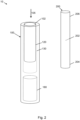
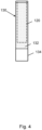
- Figures 3 and 4 are side views of the IR heating system 130.
- Figure 3 shows the IR heating system 130 with the consumable 200 received into the consumable chamber 120
- Figure 4 shows the IR heating system 130 without the consumable 200.
- the IR heating system 130 comprises an IR source, i.e. a source of IR radiation for heating the consumable 200 in the consumable chamber 120. Any suitable choice of IR source may be used.
- the IR source is provided as an electrothermal element 132 which is configured to emit IR radiation when receiving an electrical current.
- the aerosol generating device 100 comprises a power supply 180 to which the electrothermal element 132 is connectable so that the electrothermal element 132 may in use receive electrical power from the aerosol generating device 100.
- the electrothermal element 132 is an electrothermal coating, e.g. a nanocoating, configured to emit IR radiation when receiving an electrical current.
- the IR heating system 130 comprises a chamber body 134.
- the chamber body 134 is a cylinder into which the consumable chamber 120 extends while the electrothermal element 132 is applied onto an external surface.
- the chamber body 134 is comparatively transparent to IR radiation as emitted by the electrothermal element 132.
- the chamber body 134 is made from quartz glass.
- the heating chamber 110 may include a body of quartz glass with a nanocoating sandwiched in the middle, wherein the nanocoating dictates the wavenumbers which are emitted into the consumable 200, e.g. a heated tobacco stick.
- the electrothermal element 132 fully encloses the consumable chamber 120.
- the consumable chamber 120 in this example is substantially cylindrical, and the electrothermal element 132 extends about the consumable chamber 120 in a circumferential direction perpendicular to the insertion direction 105. Conversely, the electrothermal element 132 encloses the consumable chamber 120 radially.
- insertion of the consumable 200 into the aerosol generating device 100 through the consumable opening 102 by a user causes the consumable 200 to be received into the consumable chamber 120. More particularly, the device end 204 of the consumable 200 is located in the consumable chamber 120 while the mouth end 206 extends from the aerosol generating device 100.
- the aerosol generating device 100 is configured to generate aerosol/vapour for inhalation by the user through heating of the consumable 200 by means of the IR heating system 130 as part of a session.
- the IR heating system 130 is configured to heat the consumable 200 to a suitable temperature, e.g. in a range of 180 degrees Celsius to 250 degrees Celsius.
- the IR heating system 130 is electrically connectable to a power source 180, for example when the consumable 200 is engaged with the aerosol generating device 100.
- the electrothermal element 132 is connectable to the power source 180.
- the IR heating system 130 emits IR radiation which may be absorbed by the consumable 200, thereby increasing a temperature of the consumable 200.
- the IR heating system 130 is configured to emit IR radiation having specific wavenumbers, more particularly wavenumbers in a first wavenumber range and a second wavenumber range.
- the first wavenumber range is 3600 to 2900 inverse-centimetres
- the second wavenumber range is 1700 to 800 inverse-centimetres.
- the consumable 200 exhibits a comparatively high absorbance for IR radiation with wavenumbers in the first wavenumber range and the second wavenumber range
- Figure 5 shows experimental data showing an absorbance spectrum of the consumable 200.
- the data has been obtained using Fourier-transform infrared spectroscopy ("FTIR” spectroscopy).
- FTIR Fourier-transform infrared spectroscopy
- the absorbance spectrum is recorded for wavenumbers in a range of approximately 4000 to 700 and varies between approximately 0.012 and 0.23.
- a first region of comparatively high absorbance is shown in Figure 5 for wavenumbers in a range of around 3600 to 2600 inverse-centimetres.
- the first region has a first local maximum at around 3300 inverse-centimetres.
- the first region has a second local maximum at around 2900 inverse-centimetres.
- a second region of comparatively high absorbance is shown in Figure 5 for wavenumbers in a range of around 1700 to 700 inverse-centimetres.
- the second region has a first local maximum at around 1400 inverse-centimetres; a second local maximum at around 1300 inverse-centimetres, a third local maximum at around 1150 inverse-centimetres, a fourth local maximum at around 1100 inverse-centimetres, a fifth local maximum at around 1150 inverse-centimetres, a sixth local maximum at round 1000 inverse-centimetres, and a seventh local maximum at around 900 inverse-centimetres.
- Figure 5 illustrates that particular IR radiation of certain wavenumbers is preferentially absorbed into tobacco, other ingredients and components of the consumable 200.
- Utilising the wavenumbers associated with greatest absorbency may improve sensory experience for the user by increasing the amount of vapour released from the tobacco portion, and therefore nicotine. Moreover, this may reduce energy consumption and achieve a more efficient means of heating.
- infrared heating also releases similar or improved ACM output at much lower temperatures (such as 180-250 degrees Celsius), which may reduce potentially harmful substance being released (such as acetaldehyde, NNK, formaldehyde, acrolein, carbon monoxide) when compared to at least some other known heating technologies.
- the IR heating system 130 may be configured to emit IR radiation with wavenumbers corresponding to all, some, or at least one of the wavenumbers identified as local maxima of the absorption spectrum.
- the IR heating system 130 is tuned to a particular wavenumbers, and optionally also temperature range, that may be most effective for the consumable 200.
- the IR heating system 130 is configured to emit IR radiation having wavenumbers in the first wavenumber range, which approximately matches the first region of comparatively high absorbance of the consumable 200, and having wavenumbers in the second wavenumber range, which approximately matches the second region of comparatively high absorbance. That is to say, the IR radiation has wavenumbers in both wavenumber ranges.
- the emission spectrum of the IR heating system 130 may at least partially match the absorption spectrum of the consumable 200. It follows that the IR radiation emitted by the IR heating system 130 has a comparatively high probability of being absorbed by the consumable 200 and, therefore, may achieve improved efficiency of heating of the consumable 200.
- the IR heating system 130 is configured to exclusively emit IR radiation with wavenumbers in the first wavenumber range and the second wavenumber range, while in further examples the IR heating system 130 is configured to preferentially do so. That is to say, the IR heating system 130 may be configured to predominantly, but not necessarily exclusively emit IR radiation having wavenumbers in the first wavenumber range and the second wavenumber range. For example, at least 50% of the IR radiation emitted by the IR heating system 130 may have wavenumbers in the first wavenumber range and the second wavenumber range, or preferably at least 70%, and more preferably at least 90%. Thus, the emission spectrum of the IR heating system 130 may preferentially be in the first wavenumber range and the second wavenumber range, or may exclusively be in the first wavenumber range and the second wavenumber range.
- the IR heating system 130 emits IR radiation with wavenumbers in both wavenumber ranges.
- the IR radiation may have wavenumbers in one wavenumber range but not necessarily in the other wavenumber range.
- the IR heating system 130 emits IR radiation with a spectrum of wavenumbers across each of the wavenumber ranges, or across at least the first wavenumber range or the second wavenumber range.
- the emission spectrum of the IR heating system 130 may preferentially include wavenumbers of 1500 to 1200 inverse-centimetres, and preferably 1450 to 1300 inverse-centimetres.
- the emission spectrum of the IR heating system 130 may preferentially include wavenumbers of 1200 to 900 inverse-centimetres, and preferably 1100 to 1000 inverse-centimetres.
- the emission spectrum of the IR heating system 130 may preferentially include wavenumbers of 3500 to 3000 inverse-centimetres, and preferably 3400 to 3200 inverse-centimetres. Similarly, the emission spectrum of the IR heating system 130 may preferentially include wavenumbers of 3000 to 2900 inverse-centimetres.
- the aerosol generating device 100 comprises a plurality of electrothermal elements 132.
- the plurality of electrothermal elements 132 may be arranged about the consumable chamber 120 in any suitable arrangement.
- the plurality of electrothermal elements 132 may be arranged in alternating fashion along the consumable chamber 120, for example lengthwise or transverse.
- the plurality of electrothermal elements 132 may include a first set of electrothermal elements 132 and a second set of electrothermal elements 132.
- the first set of electrothermal elements 132 is configured to generate IR radiation having a first set of wavenumbers and the second set of electrothermal elements 132 is configured to generate IR radiation having a second set of wavenumbers.
- Each set of wavenumbers may include at least one wavenumber, and the first set of wavenumbers is different from the second set of wavenumbers.
Landscapes
- Catching Or Destruction (AREA)
Abstract
There is provided an aerosol generating device (100), comprising a consumable chamber (120) for receiving a consumable (200); an IR heating system (130) configured to emit IR radiation into the consumable chamber; wherein the IR heating system is configured to emit IR radiation with a wavenumber in a first wavenumber range or a second wavenumber range, wherein the first wavenumber range is 3600 to 2900 inverse-centimetres, the second wavenumber range is 1700 to 800 inverse-centimetres.
Description
- The present invention relates to an aerosol generating device and an aerosol generating system.
- A typical aerosol generating device may comprise a power supply, an aerosol generating unit that is driven by the power supply, an aerosol precursor, which in use is aerosolised by the aerosol generating unit to generate an aerosol, and a delivery system for delivery of the aerosol to a user.
- A drawback with known aerosol generating devices is that the aerosol generating unit may be required to reach a relatively high temperature such that sufficient heat permeates the aerosol precursor for aerosolising the aerosol precursor.
- In spite of the effort already invested in the development of aerosol generating devices/systems further improvements are desirable.
- At its most general, the present invention relates to an aerosol generating device having an infrared ("IR") heating system to generate infrared radiation having a wavenumber in a specified wavenumber range.
- According to a first aspect of the present invention, there is provided an aerosol generating device comprising a consumable chamber for receiving a consumable; an IR heating system configured to emit into the consumable chamber IR radiation with a wavenumber in a first wavenumber range or a second wavenumber range, wherein the first wavenumber range is 3600 to 2900 inverse-centimetres, the second wavenumber range is 1700 to 800 inverse-centimetres.
- Optionally, the second wavenumber range is 1500 to 1200 inverse-centimetres, and preferably 1450 to 1300 inverse-centimetres.
- Optionally, the second wavenumber range is 1200 to 900 inverse-centimetres, and preferably 1100 to 1000 inverse-centimetres.
- Optionally, the first wavenumber range is 3500 to 3000 inverse-centimetres, and preferably 3400 to 3200 inverse-centimetres.
- Optionally, the first wavenumber range is 3000 to 2900 inverse-centimetres.
- Optionally, an emission spectrum or an intensity distribution of the IR heating system has a local maximum at a wavenumber in the first wavenumber range or the second wavenumber range.
- Optionally, the emission spectrum or the intensity distribution has a plurality of local maxima, wherein each local maximum of the plurality of local maxima has a wavenumber in the first wavenumber range or the second wavenumber range.
- Optionally, the IR radiation has a distribution of wavenumbers including a first wavenumber in the first wavenumber range, and a second wavenumber in the second wavenumber range.
- Optionally, the IR heating system is configured to generate IR radiation with wavenumbers exclusively in the first wavenumber range or the second wavenumber range.
- Optionally, the IR radiation has a continuous spectrum of wavenumbers across the first wavenumber range or the second wavenumber range.
- Optionally, the IR heating system is configured for heating the consumable to a temperature of 180 to 250 degrees Celsius, preferably 180 degrees Celsius to 235 degrees Celsius, and more preferably 180 degrees Celsius to 220 degrees Celsius.
- Optionally, the IR heating system comprises an electrothermal element (132) configured to generate the IR radiation.
- Optionally, the electrothermal element is a nanocoating applied to a chamber body (134) enclosing the consumable chamber.
- Optionally, a plurality of electrothermal elements is provided.
- Optionally, the plurality of electrothermal elements comprises a first set of electrothermal elements and a second set of electrothermal elements.
- Optionally, each electrothermal element of the first set of electrothermal elements is configured to generate IR radiation having a first set of wavenumbers.
- Optionally, each electrothermal element of the second set of electrothermal elements is configured to generate IR radiation having a second set of wavenumbers.
- Optionally, the first set of electrothermal elements and the second set of electrothermal elements are alternatingly arranged about the consumable chamber.
- According to a second aspect of the present invention, there is provided an aerosol generating system comprising an aerosol generating device as described above and further comprising a consumable. The consumable may also be referred to as a smoking substrate. The consumable may include tobacco and/or a non-tobacco substrate.
- Optionally, an absorbance spectrum of the consumable has a local maximum in the first wavenumber range or the second wavenumber range.
- According to a third aspect, there is provided a method of analysing a smoking substrate comprising: providing a smoking substrate; performing infrared spectroscopy on the smoking substrate to generate a dataset indicative of an infrared absorbance spectrum of the smoking substrate; determining at least one wavenumber range based on the infrared absorbance spectrum.
- The at least one wavenumber range may include a wavenumber which corresponds to a local maximum in the absorbance spectrum.
- The smoking substrate may include tobacco. The smoking substrate may include a non-tobacco substrate.
- According to a fourth aspect, there is provided a method of configuring an IR heating system, including the method according to the third aspect and further comprising configuring an IR heating system to emit IR radiation with a wavenumber in the at least one wavenumber range.
- According to a fifth aspect, there is provided a method for use in manufacturing an aerosol generating device according to the first aspect, including the method according to the fourth aspect, and further comprising arranging the IR heating system to emit the IR radiation into the consumable chamber of the aerosol generating device.
- The invention includes the combination of the aspects and preferred features described except where such a combination is clearly impermissible or expressly avoided.
- So that the invention may be understood, and so that further aspects and features thereof may be appreciated, embodiments and experiments illustrating the principles of the invention will now be discussed in further detail with reference to the accompanying figures, in which:
-
Figure 1 is a perspective view of an aerosol generating system in an engaged state. -
Figure 2 is a perspective view of an aerosol generating system in a disengaged state. -
Figure 3 is a side view of an IR heater system of the aerosol generating system, including a consumable. -
Figure 4 is another side view of the IR heater system, without the consumable. -
Figure 5 shows experimental data of absorbance of the consumable for a range of IR wavenumbers. - Before describing several examples implementing the present disclosure, it is to be understood that the present disclosure is not limited by specific construction details or process steps set forth in the following description and accompanying drawings. Rather, it will be apparent to those skilled in the art having the benefit of the present disclosure that the systems, apparatuses and/or methods described herein could be embodied differently and/or be practiced or carried out in various alternative ways.
- Unless otherwise defined herein, scientific and technical terms used in connection with the presently disclosed inventive concept(s) shall have the meanings that are commonly understood by those of ordinary skill in the art, and known techniques and procedures may be performed according to conventional methods well known in the art and as described in various general and more specific references that may be cited and discussed in the present specification.
- All examples implementing the present disclosure can be made and executed without undue experimentation in light of the present disclosure. While particular examples have been described, it will be apparent to those of skill in the art that variations may be applied to the systems, apparatus, and/or methods and in the steps or in the sequence of steps of the methods described herein without departing from the concept, spirit, and scope of the inventive concept(s). All such similar substitutions and modifications apparent to those skilled in the art are deemed to be within the spirit, scope, and concept of the inventive concept(s) as defined by the appended claims.
- The use of the term "a" or "an" in the claims and/or the specification may mean "one," as well as "one or more," "at least one," and "one or more than one." As such, the terms "a," "an," and "the," as well as all singular terms, include plural referents unless the context clearly indicates otherwise. Likewise, plural terms shall include the singular unless otherwise required by context.
- The use of the term "or" in the present disclosure (including the claims) is used to mean an inclusive "and/or" unless explicitly indicated to refer to alternatives only or unless the alternatives are mutually exclusive. For example, a condition "A or B" is satisfied by any of the following: A is true (or present) and B is false (or not present), A is false (or not present) and B is true (or present), and both A and B are true (or present).
- As used in this specification and claim(s), the words "comprising, "having," "including," or "containing" (and any forms thereof, such as "comprise" and "comprises," "have" and "has," "includes" and "include," or "contains" and "contain," respectively) are inclusive or open-ended and do not exclude additional, unrecited elements or method steps.
- Unless otherwise explicitly stated as incompatible, or the physics or otherwise of the embodiments, examples, or claims prevent such a combination, the features of examples disclosed herein, and of the claims, may be integrated together in any suitable arrangement, especially ones where there is a beneficial effect in doing so. This is not limited to only any specified benefit, and instead may arise from an "ex post facto" benefit. This is to say that the combination of features is not limited by the described forms, particularly the form (e.g. numbering) of example(s), embodiment(s), or dependency of claim(s). Moreover, this also applies to the phrase "in one embodiment," "according to an embodiment," and the like, which are merely a stylistic form of wording and are not to be construed as limiting the following features to a separate embodiment to all other instances of the same or similar wording. This is to say, a reference to `an,' 'one,' or 'some' embodiment(s) may be a reference to any one or more, and/or all embodiments, or combination(s) thereof, disclosed. Also, similarly, the reference to "the" embodiment may not be limited to the immediately preceding embodiment. Further, all references to one or more embodiments or examples are to be construed as non-limiting to the claims.
- The present disclosure may be better understood in view of the following explanations, wherein the terms used that are separated by "or" may be used interchangeably:
As used herein, an "aerosol generating apparatus" (or "electronic(e)-cigarette" or "aerosol generating device") may be an apparatus configured to deliver an aerosol to a user for inhalation by the user. The apparatus may additionally/alternatively be referred to as a "smoking substitute apparatus", if it is intended to be used instead of a conventional combustible smoking article. As used herein a combustible "smoking article" may refer to a cigarette, cigar, pipe or other article, that produces smoke (an aerosol comprising solid particulates and gas) via heating above the thermal decomposition temperature (typically by combustion and/or pyrolysis). An aerosol generated by the apparatus may comprise an aerosol with particle sizes of 0.2 - 7 microns, or less than 10 microns, or less than 7 microns. This particle size may be achieved by control of one or more of: heater temperature; cooling rate as the vapour condenses to an aerosol; flow properties including turbulence and velocity. The generation of aerosol by the aerosol generating apparatus may be controlled by an input device. The input device may be configured to be user-activated, and may for example include or take the form of an actuator (e.g. actuation button) and/or an airflow sensor. - Each occurrence of the aerosol generating apparatus being caused to generate aerosol for a period of time (which may be variable) may be referred to as an "activation" of the aerosol generating apparatus. The aerosol generating apparatus may be arranged to allow an amount of aerosol delivered to a user to be varied per activation (as opposed to delivering a fixed dose of aerosol), e.g. by activating an aerosol generating unit of the apparatus for a variable amount of time, e.g. based on the strength/duration of a draw of a user through a flow path of the apparatus (to replicate an effect of smoking a conventional combustible smoking article).
- The aerosol generating apparatus may be portable. As used herein, the term "portable" may refer to the apparatus being for use when held by a user.
- As used herein, an "aerosol generating system" may be a system that includes an aerosol generating apparatus and optionally other circuitry/components associated with the function of the apparatus, e.g. one or more external devices and/or one or more external components (here "external" is intended to mean external to the aerosol generating apparatus). As used herein, an "external device" and "external component" may include one or more of a: a charging device, a mobile device (which may be connected to the aerosol generating apparatus, e.g. via a wireless or wired connection); a networked-based computer (e.g. a remote server); a cloud-based computer; any other server system.
- An example aerosol generating system may be a system for managing an aerosol generating apparatus. Such a system may include, for example, a mobile device, a network server, as well as the aerosol generating apparatus.
- As used herein, an "aerosol" may include a suspension of precursor, including as one or more of: solid particles; liquid droplets; gas. Said suspension may be in a gas including air. An aerosol herein may generally refer to/include a vapour. An aerosol may include one or more components of the precursor. As used herein, a "precursor" may include one or more of a: liquid; solid; gel; loose leaf material; other substance. The precursor may be processed by an aerosol generating unit of an aerosol generating apparatus to generate an aerosol. The precursor may include one or more of: an active component; a carrier; a flavouring. The active component may include one or more of nicotine; caffeine; a cannabidiol oil; a non-pharmaceutical formulation, e.g. a formulation which is not for treatment of a disease or physiological malfunction of the human body. The active component may be carried by the carrier, which may be a liquid, including propylene glycol and/or glycerine. The term "flavouring" may refer to a component that provides a taste and/or a smell to the user. The flavouring may include one or more of: Ethylvanillin (vanilla); menthol, Isoamyl acetate (banana oil); or other. The precursor may include a substrate, e.g. reconstituted tobacco to carry one or more of the active component; a carrier; a flavouring.
- As used herein, a "storage portion" may be a portion of the apparatus adapted to store the precursor. It may be implemented as a carrier for solid material depending on the implementation of the precursor as defined above.
- As used herein, a "flow path" may refer to a path or enclosed passageway through an aerosol generating apparatus, e.g. for delivery of an aerosol to a user. The flow path may be arranged to receive aerosol from an aerosol generating unit. When referring to the flow path, upstream and downstream may be defined in respect of a direction of flow in the flow path, e.g. with an outlet being downstream of an inlet.
- As used herein, a "delivery system" may be a system operative to deliver an aerosol to a user. The delivery system may include a mouthpiece and a flow path.
- As used herein, a "flow" may refer to a flow in a flow path. A flow may include aerosol generated from the precursor. The flow may include air, which may be induced into the flow path via a puff by a user.
- As used herein, a "puff" (or "inhale" or "draw") by a user may referto expansion of lungs and/or oral cavity of a user to create a pressure reduction that induces flow through the flow path.
- As used herein, an "aerosol generating unit" may referto a device configured to generate an aerosol from a precursor. The aerosol generating unit may include a unit to generate a vapour directly from the precursor (e.g. a heating system or other system) or an aerosol directly from the precursor (e.g. an atomiser including an ultrasonic system, a flow expansion system operative to carry droplets of the precursor in the flow without using electrical energy or other system). A plurality of aerosol generating units to generate a plurality of aerosols (for example, from a plurality of different aerosol precursors) may be present in an aerosol generating apparatus.
- As used herein, a "heating system" (for example an IR heating system) may refer to an arrangement of at least one heating element, which is operable to aerosolise a precursor once heated. The heating system may be configured to heat a precursor without combustion.
- As used herein, a "consumable" may refer to a unit that includes a precursor. The consumable may include an aerosol generating unit, e.g. it may be arranged as a cartomizer. The consumable may include a mouthpiece. With solid material implementations of the precursor, e.g. tobacco or reconstituted tobacco formulation, the consumable may be referred to as a "stick" or "package" or "heat-not-burn consumable". In a heat-not-burn consumable, the mouthpiece may be implemented as a filter and the consumable may be arranged to carry the precursor. The consumable may be implemented as a dosage or pre-portioned amount of material, including a loose-leaf product.
- As used herein "heat-not-burn" (or "HNB" or "heated precursor") may refer to the heating of a precursor, typically tobacco, without combustion, or without substantial combustion (i.e. localised combustion may be experienced of limited portions of the precursor, including of less than 5% of the total volume).
- Aspects and embodiments of the present invention will now be discussed with reference to the accompanying figures. Further aspects and embodiments will be apparent to those skilled in the art.
-
Figures 1 and2 are perspective views of a heat-not-burn system 10 for providing aerosol/vapour to a user. Herein, "heat-not-burn" is abbreviated as HNB. - The
aerosol generating system 10 comprises aaerosol generating device 100 and an aerosol-forming article in the form of a consumable 200. Theaerosol generating device 100 and the consumable 200 are configured such that the consumable 200 can be engaged with theaerosol generating device 100.Figure 1 shows theaerosol generating device 100 and the consumable 200 in an engaged state, whilstFigure 2 shows theaerosol generating device 100 and the consumable 200 in a disengaged state. Suitably, theaerosol generating device 100 has a consumable opening 102 (shown inFigure 3 as a dashed-dotted line). The consumable 200 is insertable into theaerosol generating device 100 through theconsumable opening 102 in aninsertion direction 105. - The consumable 200 generally resembles a cigarette and may also be referred to as a stick consumable or as a stick. In that respect, the consumable 200 has a generally cylindrical form with a diameter of 7 mm and an axial length of 70 mm, where "mm" represents the physical unit of millimetres.
- The consumable 200 includes a
device end 204 and amouth end 206. In use, thedevice end 204 is received into theaerosol generating device 100 while themouth end 206 extends from theaerosol generating device 100 for a user to engage for inhalation. Thedevice end 204 and themouth end 206 may be structurally different, for example themouth end 206 may include a filter. - The consumable 200 comprises an aerosol former 202. The
aerosol generating device 100 is configured to vaporise the aerosol former 202 by heating the aerosol former 202 (so as to form a vapour/aerosol for inhalation by a user). Suitably, theaerosol generating device 100 comprises aheating chamber 110 which includes aconsumable chamber 120 and anIR heating system 130. Herein, "IR" is used as an abbreviation for infrared. - The
consumable chamber 120 is a generally elongate recess, which in this example is substantially cylindrical, into which the consumable 200 is insertable. Suitably, the consumable 200 is insertable into theconsumable chamber 120 through theconsumable opening 102 in theinsertion direction 105. In some examples, theinsertion direction 105 is perpendicular to theconsumable opening 102. - The
IR heating system 130 is configured to generate IR radiation, i.e. infrared radiation, for heating of the consumable 200 when the consumable 200 is received into theconsumable chamber 120. IR radiation may include radiation of wavelengths of around 700 nanometres to 1 millimetre or, correspondingly, wavenumbers of around 1429 to 10 inverse-centimetres; where wavenumber corresponds to the inverse wavelength. The wavenumber has a unit of "inverse-centimetres", which may also be denoted as cm-1 ("cm" with superscript "-1") or cm-1 (without superscript) or 1/cm. Here, ranges of wavenumbers are ordered in accordance with customary practice in infrared spectroscopy, according to which higher energies (corresponding to larger wavenumbers) are recorded towards the left on graphs and lower energies (corresponding to smaller wavenumbers) are recorded towards the right; cf.Figure 5 . - Infrared may require much lower temperatures (e.g. 180 degrees Celsius to 250 degrees Celsius) of heating in order to release a similar amount of aerosol collected matter ("ACM") when compared to at least some known heating technologies (e.g. 345 degrees Celsius). Nicotine may be released into vapor form in a region of 180 degrees Celsius to 220 degrees Celsius, which may make IR heating the preferred form of heating tobacco in at least some applications.
-
Figures 3 and4 are side views of theIR heating system 130.Figure 3 shows theIR heating system 130 with the consumable 200 received into theconsumable chamber 120, whileFigure 4 shows theIR heating system 130 without the consumable 200. - The
IR heating system 130 comprises an IR source, i.e. a source of IR radiation for heating the consumable 200 in theconsumable chamber 120. Any suitable choice of IR source may be used. In the present example, the IR source is provided as anelectrothermal element 132 which is configured to emit IR radiation when receiving an electrical current. Suitably theaerosol generating device 100 comprises apower supply 180 to which theelectrothermal element 132 is connectable so that theelectrothermal element 132 may in use receive electrical power from theaerosol generating device 100. - In this example, the
electrothermal element 132 is an electrothermal coating, e.g. a nanocoating, configured to emit IR radiation when receiving an electrical current. - The
IR heating system 130 comprises achamber body 134. As shown inFigures 1 to 4 , thechamber body 134 is a cylinder into which theconsumable chamber 120 extends while theelectrothermal element 132 is applied onto an external surface. Suitably thechamber body 134 is comparatively transparent to IR radiation as emitted by theelectrothermal element 132. In this example, thechamber body 134 is made from quartz glass. - In some examples, the
heating chamber 110 may include a body of quartz glass with a nanocoating sandwiched in the middle, wherein the nanocoating dictates the wavenumbers which are emitted into the consumable 200, e.g. a heated tobacco stick. - In
Figures 1 to 4 , theelectrothermal element 132 fully encloses theconsumable chamber 120. As outlined above, theconsumable chamber 120 in this example is substantially cylindrical, and theelectrothermal element 132 extends about theconsumable chamber 120 in a circumferential direction perpendicular to theinsertion direction 105. Conversely, theelectrothermal element 132 encloses theconsumable chamber 120 radially. - In use, insertion of the consumable 200 into the
aerosol generating device 100 through theconsumable opening 102 by a user causes the consumable 200 to be received into theconsumable chamber 120. More particularly, thedevice end 204 of the consumable 200 is located in theconsumable chamber 120 while themouth end 206 extends from theaerosol generating device 100. - The
aerosol generating device 100 is configured to generate aerosol/vapour for inhalation by the user through heating of the consumable 200 by means of theIR heating system 130 as part of a session. Suitably theIR heating system 130 is configured to heat the consumable 200 to a suitable temperature, e.g. in a range of 180 degrees Celsius to 250 degrees Celsius. Conveniently, theIR heating system 130 is electrically connectable to apower source 180, for example when the consumable 200 is engaged with theaerosol generating device 100. In this example, theelectrothermal element 132 is connectable to thepower source 180. - The
IR heating system 130 emits IR radiation which may be absorbed by the consumable 200, thereby increasing a temperature of the consumable 200. TheIR heating system 130 is configured to emit IR radiation having specific wavenumbers, more particularly wavenumbers in a first wavenumber range and a second wavenumber range. The first wavenumber range is 3600 to 2900 inverse-centimetres, while the second wavenumber range is 1700 to 800 inverse-centimetres. Conveniently, the consumable 200 exhibits a comparatively high absorbance for IR radiation with wavenumbers in the first wavenumber range and the second wavenumber range -
Figure 5 shows experimental data showing an absorbance spectrum of the consumable 200. The data has been obtained using Fourier-transform infrared spectroscopy ("FTIR" spectroscopy). - According to
Figure 5 , the absorbance spectrum is recorded for wavenumbers in a range of approximately 4000 to 700 and varies between approximately 0.012 and 0.23. - A first region of comparatively high absorbance is shown in
Figure 5 for wavenumbers in a range of around 3600 to 2600 inverse-centimetres. The first region has a first local maximum at around 3300 inverse-centimetres. The first region has a second local maximum at around 2900 inverse-centimetres. - A second region of comparatively high absorbance is shown in
Figure 5 for wavenumbers in a range of around 1700 to 700 inverse-centimetres. The second region has a first local maximum at around 1400 inverse-centimetres; a second local maximum at around 1300 inverse-centimetres, a third local maximum at around 1150 inverse-centimetres, a fourth local maximum at around 1100 inverse-centimetres, a fifth local maximum at around 1150 inverse-centimetres, a sixth local maximum atround 1000 inverse-centimetres, and a seventh local maximum at around 900 inverse-centimetres. -
Figure 5 illustrates that particular IR radiation of certain wavenumbers is preferentially absorbed into tobacco, other ingredients and components of the consumable 200. Utilising the wavenumbers associated with greatest absorbency may improve sensory experience for the user by increasing the amount of vapour released from the tobacco portion, and therefore nicotine. Moreover, this may reduce energy consumption and achieve a more efficient means of heating. Furthermore, since infrared heating also releases similar or improved ACM output at much lower temperatures (such as 180-250 degrees Celsius), which may reduce potentially harmful substance being released (such as acetaldehyde, NNK, formaldehyde, acrolein, carbon monoxide) when compared to at least some other known heating technologies. - The
IR heating system 130 may be configured to emit IR radiation with wavenumbers corresponding to all, some, or at least one of the wavenumbers identified as local maxima of the absorption spectrum. - As such, the
IR heating system 130 is tuned to a particular wavenumbers, and optionally also temperature range, that may be most effective for the consumable 200. TheIR heating system 130 is configured to emit IR radiation having wavenumbers in the first wavenumber range, which approximately matches the first region of comparatively high absorbance of the consumable 200, and having wavenumbers in the second wavenumber range, which approximately matches the second region of comparatively high absorbance. That is to say, the IR radiation has wavenumbers in both wavenumber ranges. - As such, the emission spectrum of the
IR heating system 130 may at least partially match the absorption spectrum of the consumable 200. It follows that the IR radiation emitted by theIR heating system 130 has a comparatively high probability of being absorbed by the consumable 200 and, therefore, may achieve improved efficiency of heating of the consumable 200. - In some examples, the
IR heating system 130 is configured to exclusively emit IR radiation with wavenumbers in the first wavenumber range and the second wavenumber range, while in further examples theIR heating system 130 is configured to preferentially do so. That is to say, theIR heating system 130 may be configured to predominantly, but not necessarily exclusively emit IR radiation having wavenumbers in the first wavenumber range and the second wavenumber range. For example, at least 50% of the IR radiation emitted by theIR heating system 130 may have wavenumbers in the first wavenumber range and the second wavenumber range, or preferably at least 70%, and more preferably at least 90%. Thus, the emission spectrum of theIR heating system 130 may preferentially be in the first wavenumber range and the second wavenumber range, or may exclusively be in the first wavenumber range and the second wavenumber range. - In some examples, the
IR heating system 130 emits IR radiation with wavenumbers in both wavenumber ranges. In further examples, the IR radiation may have wavenumbers in one wavenumber range but not necessarily in the other wavenumber range. - In some examples, the
IR heating system 130 emits IR radiation with a spectrum of wavenumbers across each of the wavenumber ranges, or across at least the first wavenumber range or the second wavenumber range. As such, the emission spectrum of theIR heating system 130 may preferentially include wavenumbers of 1500 to 1200 inverse-centimetres, and preferably 1450 to 1300 inverse-centimetres. Similarly, the emission spectrum of theIR heating system 130 may preferentially include wavenumbers of 1200 to 900 inverse-centimetres, and preferably 1100 to 1000 inverse-centimetres. Similarly, the emission spectrum of theIR heating system 130 may preferentially include wavenumbers of 3500 to 3000 inverse-centimetres, and preferably 3400 to 3200 inverse-centimetres. Similarly, the emission spectrum of theIR heating system 130 may preferentially include wavenumbers of 3000 to 2900 inverse-centimetres. - In some examples, the
aerosol generating device 100 comprises a plurality ofelectrothermal elements 132. The plurality ofelectrothermal elements 132 may be arranged about theconsumable chamber 120 in any suitable arrangement. For example, the plurality ofelectrothermal elements 132 may be arranged in alternating fashion along theconsumable chamber 120, for example lengthwise or transverse. - Where a plurality of
electrothermal elements 132 is provided, the plurality ofelectrothermal elements 132 may include a first set ofelectrothermal elements 132 and a second set ofelectrothermal elements 132. The first set ofelectrothermal elements 132 is configured to generate IR radiation having a first set of wavenumbers and the second set ofelectrothermal elements 132 is configured to generate IR radiation having a second set of wavenumbers. Each set of wavenumbers may include at least one wavenumber, and the first set of wavenumbers is different from the second set of wavenumbers. - The features disclosed in the foregoing description, or in the following claims, or in the accompanying drawings, expressed in their specific forms or in terms of a means for performing the disclosed function, or a method or process for obtaining the disclosed results, as appropriate, may, separately, or in any combination of such features, be utilised for realising the invention in diverse forms thereof.
- While the invention has been described in conjunction with the exemplary embodiments described above, many equivalent modifications and variations will be apparent to those skilled in the art when given this disclosure. Accordingly, the exemplary embodiments of the invention set forth above are considered to be illustrative and not limiting. Various changes to the described embodiments may be made without departing from the spirit and scope of the invention.
- For the avoidance of any doubt, any theoretical explanations provided herein are provided for the purposes of improving the understanding of a reader. The inventors do not wish to be bound by any of these theoretical explanations.
- Any section headings used herein are for organizational purposes only and are not to be construed as limiting the subject matter described.
- Throughout this specification, including the claims which follow, unless the context requires otherwise, the words "have", "comprise", and "include", and variations such as "having", "comprises", "comprising", and "including" will be understood to imply the inclusion of a stated integer or step or group of integers or steps but not the exclusion of any other integer or step or group of integers or steps.
- It must be noted that, as used in the specification and the appended claims, the singular forms "a," "an," and "the" include plural referents unless the context clearly dictates otherwise. Ranges may be expressed herein as from "about" one particular value, and/or to "about" another particular value. When such a range is expressed, another embodiment includes from the one particular value and/or to the other particular value. Similarly, when values are expressed as approximations, by the use of the antecedent "about," it will be understood that the particular value forms another embodiment. The term "about" in relation to a numerical value is optional and means, for example, +/- 10%.
- The words "preferred" and "preferably" are used herein refer to embodiments of the invention that may provide certain benefits under some circumstances. It is to be appreciated, however, that other embodiments may also be preferred under the same or different circumstances. The recitation of one or more preferred embodiments therefore does not mean or imply that other embodiments are not useful, and is not intended to exclude other embodiments from the scope of the disclosure, or from the scope of the claims.
Claims (15)
- A aerosol generating device (100), comprising:a consumable chamber (120) for receiving a consumable (200);an IR heating system (130) configured to emit into the consumable chamber IR radiation with a wavenumber in a first wavenumber range or a second wavenumber range, whereinthe first wavenumber range is 3600 to 2900 inverse-centimetres,the second wavenumber range is 1700 to 800 inverse-centimetres.
- The aerosol generating device according to claim 1,
wherein the second wavenumber range is 1500 to 1200 inverse-centimetres, and preferably 1450 to 1300 inverse-centimetres. - The aerosol generating device according to claim 1,
wherein the second wavenumber range is 1200 to 900 inverse-centimetres, and preferably 1100 to 1000 inverse-centimetres. - The aerosol generating device according to any preceding claim,
wherein the first wavenumber range is 3500 to 3000 inverse-centimetres, and preferably 3400 to 3200 inverse-centimetres. - The aerosol generating device according to any one of claims 1 to 3,
wherein the first wavenumber range is 3000 to 2900 inverse-centimetres. - The aerosol generating device according to any preceding claim,
wherein an emission spectrum of the IR heating system has a local maximum at a wavenumber in the first wavenumber range or the second wavenumber range. - The aerosol generating device according to any preceding claim,
wherein the IR radiation has a distribution of wavenumbers including a first wavenumber in the first wavenumber range, and a second wavenumber in the second wavenumber range. - The aerosol generating device according to any preceding claim,
wherein the IR heating system is configured to generate IR radiation with wavenumbers exclusively in the first wavenumber range or the second wavenumber range. - The aerosol generating device according to any preceding claim,
wherein the IR radiation has a continuous spectrum of wavenumbers across the first wavenumber range or the second wavenumber range. - The aerosol generating device according to any preceding claim,
wherein the IR heating system is configured for heating the consumable to a temperature of 180 to 250 degrees Celsius, preferably 180 degrees Celsius to 235 degrees Celsius, and more preferably 180 degrees Celsius to 220 degrees Celsius. - The aerosol generating device according to any preceding claim,
wherein the IR heating system comprises an electrothermal element (132) configured to generate the IR radiation. - The aerosol generating device according to claim 11,
wherein the electrothermal element is a nanocoating applied to a chamber body (134) enclosing the consumable chamber. - The aerosol generating device according to claim 11 or 12,
wherein a plurality of electrothermal elements (134) is provided. - The aerosol generating device according to claim 13,wherein the plurality of electrothermal elements comprises a first set of electrothermal elements (134) and a second set of electrothermal elements (134),wherein each electrothermal element of the first set is configured to generate IR radiation having a first set of wavenumbers, and each electrothermal element of the second set is configured to generate IR radiation having a second set of wavenumbers, andwherein the first set and the second set of electrothermal elements are alternatingly arranged about the consumable chamber.
- An aerosol generating system comprising an aerosol generating device according to any preceding claim,further comprising a consumable (200),wherein an absorbance spectrum of the consumable has a local maximum in the first wavenumber range or the second wavenumber range.
Priority Applications (2)
| Application Number | Priority Date | Filing Date | Title |
|---|---|---|---|
| EP23199827.9A EP4529786A1 (en) | 2023-09-26 | 2023-09-26 | Aerosol generating device and system |
| PCT/EP2024/075797 WO2025067929A1 (en) | 2023-09-26 | 2024-09-16 | Aerosol generating device and system |
Applications Claiming Priority (1)
| Application Number | Priority Date | Filing Date | Title |
|---|---|---|---|
| EP23199827.9A EP4529786A1 (en) | 2023-09-26 | 2023-09-26 | Aerosol generating device and system |
Publications (1)
| Publication Number | Publication Date |
|---|---|
| EP4529786A1 true EP4529786A1 (en) | 2025-04-02 |
Family
ID=88204247
Family Applications (1)
| Application Number | Title | Priority Date | Filing Date |
|---|---|---|---|
| EP23199827.9A Pending EP4529786A1 (en) | 2023-09-26 | 2023-09-26 | Aerosol generating device and system |
Country Status (2)
| Country | Link |
|---|---|
| EP (1) | EP4529786A1 (en) |
| WO (1) | WO2025067929A1 (en) |
Citations (3)
| Publication number | Priority date | Publication date | Assignee | Title |
|---|---|---|---|---|
| US20140202476A1 (en) * | 2011-09-06 | 2014-07-24 | British American Tobacco (Investments) Limited | Heating smokeable material |
| CN108338415A (en) * | 2017-01-25 | 2018-07-31 | 贵州中烟工业有限责任公司 | Peripheral formula heated cigarette smoking system |
| US20230055048A1 (en) * | 2020-01-15 | 2023-02-23 | Shenzhen First Union Technology Co., Ltd. | Aerosol-generating device and infrared emitter |
-
2023
- 2023-09-26 EP EP23199827.9A patent/EP4529786A1/en active Pending
-
2024
- 2024-09-16 WO PCT/EP2024/075797 patent/WO2025067929A1/en active Pending
Patent Citations (3)
| Publication number | Priority date | Publication date | Assignee | Title |
|---|---|---|---|---|
| US20140202476A1 (en) * | 2011-09-06 | 2014-07-24 | British American Tobacco (Investments) Limited | Heating smokeable material |
| CN108338415A (en) * | 2017-01-25 | 2018-07-31 | 贵州中烟工业有限责任公司 | Peripheral formula heated cigarette smoking system |
| US20230055048A1 (en) * | 2020-01-15 | 2023-02-23 | Shenzhen First Union Technology Co., Ltd. | Aerosol-generating device and infrared emitter |
Also Published As
| Publication number | Publication date |
|---|---|
| WO2025067929A1 (en) | 2025-04-03 |
Similar Documents
| Publication | Publication Date | Title |
|---|---|---|
| JP7835838B2 (en) | Cigarettes and cigarette aerosol generator | |
| KR101957819B1 (en) | Electrically-powered aerosol delivery system | |
| JP2020511967A (en) | Aerosol delivery device and related methods | |
| CN109922673B (en) | Tobacco mixture | |
| KR20210016414A (en) | Aerosol-generating articles, aerosol-generating systems, and methods for generating flavor aerosols | |
| WO2025067929A1 (en) | Aerosol generating device and system | |
| US20240284964A1 (en) | Aerosol generating system | |
| US20240284958A1 (en) | Aerosol generating system | |
| EP4505890A1 (en) | Heat-not-burn device and system | |
| EP4573939A1 (en) | Heat-not-burn consumable and apparatus | |
| EP4505889A1 (en) | Heat-not-burn device and system | |
| EP4494488A1 (en) | Aerosol generating system | |
| RU2859490C2 (en) | Aerosol-generating system | |
| EP4602949A1 (en) | Aerosol generating apparatus | |
| EP4494489A1 (en) | Aerosol generating system | |
| EP4505887A1 (en) | Heat-not-burn device and systems | |
| RU2859489C2 (en) | Solid aerosol precursor for aerosol-forming article and aerosol-forming article | |
| EP4566468A1 (en) | Heating system for an aerosol generating apparatus | |
| EP4725333A1 (en) | Aerosol generating system | |
| EP4684665A1 (en) | Aerosol-generating apparatus mouthpiece | |
| EP4663045A1 (en) | Component for an aerosol generating apparatus | |
| EP4616734A1 (en) | Aerosol generating apparatus and consumable | |
| WO2025129653A1 (en) | Aerosol generating apparatus | |
| US20240065314A1 (en) | Filter for Smoking Article | |
| WO2025172416A1 (en) | Aerosol generating apparatus |
Legal Events
| Date | Code | Title | Description |
|---|---|---|---|
| PUAI | Public reference made under article 153(3) epc to a published international application that has entered the european phase |
Free format text: ORIGINAL CODE: 0009012 |
|
| STAA | Information on the status of an ep patent application or granted ep patent |
Free format text: STATUS: THE APPLICATION HAS BEEN PUBLISHED |
|
| AK | Designated contracting states |
Kind code of ref document: A1 Designated state(s): AL AT BE BG CH CY CZ DE DK EE ES FI FR GB GR HR HU IE IS IT LI LT LU LV MC ME MK MT NL NO PL PT RO RS SE SI SK SM TR |