FIELD
-
The present disclosure relates to aerosol-generating apparatuses.
BACKGROUND
-
A typical aerosol-generating apparatus may comprise a power supply, an aerosol-generating unit that is powered by the power supply, and an aerosol precursor, where, in use, the aerosol-generating unit aerosolises the aerosol precursor to generate an aerosol for inhalation by a user of the device.
-
A first drawback with known aerosol-generating apparatuses is that airflow design can lead to increased manufacturing complexity. A second drawback is that liquid aerosol precursor can leak from the device. Hence, in spite of the effort already invested in the development of aerosol-generating apparatuses further improvements are desirable.
SUMMARY
-
The present disclosure provides an aerosol-generating apparatus that comprises:
- a housing;
- an aerosol-generating unit having a longitudinal axis, the aerosol-generating unit defining a heating chamber, the aerosol-generating unit including:
- a base part;
- a top part defining an aerosol-generating unit air outlet from the heating chamber;
- a central part connecting the base part to the top part;
- a heating system for aerosolising liquid aerosol precursor, the heating system being positioned in the heating chamber; and
- an aerosol-generating unit air inlet to the heating chamber, the aerosol-generating unit air inlet being located through the central part; wherein:
- the housing at least partially surrounds the aerosol-generating unit to form an inlet air passage in the longitudinal direction;
- the inlet air passage is located between the aerosol-generating unit and the housing; and
- the inlet air passage is configured to supply air to the aerosol-generating unit air inlet.
-
In this way, ease of manufacturing may be improved because the inlet air passage can be formed by a gap between the aerosol-generating unit and the housing thus reducing the complexity of the device. For example, this may mean the aerosol-generating unit does not need to include an integral inlet air passage (i.e. one entirely delimited by the aerosol-generating unit) which may, for example, reduce tooling complexity when the aerosol-generating unit is injection moulded. Additionally, forming the inlet air passage between the aerosol-generating unit and housing may facilitate cleaning of the inlet air passage because it may be more accessible. To facilitate this, the aerosol-generating unit and housing may jointly delimit the inlet air passage.
-
Also in this way, the likelihood of liquid aerosol precursor leaking from the aerosol-generating apparatus may be reduced because the aerosol-generating unit air inlet is above the base part of the aerosol-generating unit. In other words, any liquid aerosol precursor not aerosolised by the heating system can accumulate adjacent the base part (below the aerosol-generating unit air inlet) which may reduce the likelihood of liquid aerosol precursor leaking out of the aerosol-generating unit air inlet. Any liquid aerosol precursor accumulating adjacent the base part of the aerosol-generating unit may be aerosolised by the heating system during subsequent use of the aerosol-generating apparatus. It is beneficial to reduce the likelihood of leakage of liquid aerosol precursor to improve the user experience of the aerosol-generating apparatus.
-
The aerosol-generating unit may be elongate along its longitudinal axis. In this way, the longitudinal axis can be a major axis. The longitudinal axis may be a central axis of the aerosol-generating unit. The housing may be elongate and as such also have a (major) longitudinal axis. The longitudinal axis of the aerosol-generating unit may be parallel and/or coincident with the longitudinal axis of the housing. Thus, the aerosol-generating apparatus may itself be elongate.
-
The location of features of the aerosol-generating apparatus may be described in terms of airflow (e.g. flow paths) through the device under normal use. In normal use, the aerosol-generating apparatus may aerosolise liquid aerosol precursor for inhalation by a user of the device. Hence, air may flow through the aerosol-generating apparatus as follows:
- 1) from the external environment into the inlet air passage;
- 2) through the inlet air passage;
- 3) from the inlet air passage into the aerosol-generating unit air inlet;
- 4) through the aerosol-generating unit air inlet;
- 5) from the aerosol-generating unit air inlet into the heating chamber;
- 6) through the heating chamber (including through and/or across the heating system);
- 7) from the heating chamber into the aerosol-generating unit air outlet;
- 8) through the aerosol-generating unit air outlet; and
- 9) from the aerosol-generating unit air outlet into a user's lungs via (e.g.) the user's mouth.
-
On the basis of the above airflow. The inlet air passage may be referred to as being any one or combination of: upstream of the aerosol-generating unit air inlet; upstream of the heating chamber; and upstream of the aerosol-generating unit air outlet. The aerosol-generating unit air inlet may be referred to as being any one or combination of: downstream of the inlet air passage; upstream of the heating chamber; and upstream of the aerosol-generating unit air outlet. The heating chamber may be referred to as being any one of combination of; downstream of the inlet air passage; downstream of the aerosol-generating unit air inlet; and upstream of the aerosol-generating unit air outlet. The aerosol-generating unit air outlet may be referred to as being any one or combination of: downstream of the inlet air passage; downstream of the aerosol-generating unit air inlet; and downstream of the heating chamber. Additionally, the heating system may be referred to as being any one or combination of: downstream of the inlet air passage; downstream of the aerosol-generating unit air inlet; and upstream of the aerosol-generating unit air outlet. Air may flow through the inlet air passage parallel to the longitudinal axis. Air may flow through the aerosol-generating unit air inlet perpendicular to the longitudinal axis. Air may flow through the heating system parallel to the longitudinal axis. Air may flow across the heating system perpendicular to the longitudinal axis. Air may flow through the aerosol-generating unit air outlet parallel to the longitudinal axis.
-
The aerosol-generating unit includes a base part, a central part and a top part. The central part of the aerosol-generating unit connects the base part of the aerosol-generating unit to the top part of the aerosol-generating unit such that the aerosol-generating unit air inlet is positioned between the base part and the top part. The heating chamber may be understood to be delimited by the base part, the top part and the central part. The top part, central part and/or base part may be integrally formed. Alternatively, the top part, central part and/or base part may be separate components (e.g. not integrally formed). Suitable materials for the aerosol-generating unit may include, for example, silicone, polycarbonate (PC) and polyetheretherketone (PEEK). A top portion of the heating chamber may be delimited by the top part of the aerosol-generating unit. A bottom portion of the heating chamber may be delimited by the base part of the aerosol-generating unit. A central portion of the heating chamber may be delimited by the central part of the aerosol-generating unit. The top part of the aerosol-generating unit may converge towards the aerosol-generating unit air outlet. In this way, draw resistance may be controlled.
-
A circumferential direction of the aerosol-generating unit may be understood to be a direction which encircles the longitudinal axis of the aerosol-generating unit. The aerosol-generating unit may have various cross-sectional shapes in the longitudinal direction (that is a direction of the longitudinal axis) including but not limited to circular, elliptical or polygonal (e.g. square, triangular). In some examples, the housing at least partially surrounds the aerosol-generating unit in the circumferential direction (i.e. circumferentially) to form the inlet air passage. Thus, there can be a gap between the aerosol-generating unit and the housing that extends in the longitudinal direction such that air can be supplied to the aerosol-generating unit air inlet. The space between the aerosol-generating unit and the housing may be understood to be a cavity, recess and/or channel. In some examples, the housing fully circumferentially surrounds the aerosol-generating unit (e.g. the aerosol-generating unit is located (at least partially) within the housing). Thus, the housing may form an elongate tube in which the aerosol-generating unit is located. The aerosol-generating unit and housing may delimit an entrance to the inlet air passage. The entrance may be located in a base of the aerosol-generating apparatus. A normal to the plane defined by the perimeter of the entrance may be parallel to the longitudinal axis. The aerosol-generating unit may be held within or in contact with the housing via friction (i.e. a friction fit). Using a friction fit may facilitate assembly of the aerosol-generating apparatus. The housing may be further secured to the aerosol-generating unit using adhesive and/or other attachment means such as screws and/or clips. The housing may be metal and/or metal alloy.
-
The aerosol-generating unit air inlet may have a substantially circular cross-sectional area (i.e. the aerosol-generating unit air inlet may be substantially cylindrical). In this way, airflow uniformity through the aerosol-generating unit air inlet may be improved. The aerosol-generating unit air inlet may extend through the central part of the aerosol-generating unit in a direction perpendicular to the longitudinal axis of the aerosol-generating unit (e.g. radially with respect to the longitudinal axis). When the cross-sectional area of the aerosol-generating unit air inlet is substantially circular, the diameter of the cross-section may be 0.6mm or greater. In this way, manufacturing of the aerosol-generating unit may be facilitated (e.g. when the aerosol-generating unit is formed via injection moulding).
-
The aerosol-generating unit air outlet may have a substantially cylindrical cross-sectional area (e.g. a cross-sectional area in the longitudinal direction of the aerosol-generating unit). In some examples, an aerosol delivery structure (e.g. mouthpiece) is connected to the aerosol-generating unit air outlet. This may allow air containing aerosol to be inhaled from the aerosol delivery structure (e.g. mouthpiece) by a user of the aerosol-generating apparatus. The aerosol-generating unit air outlet may taper in the longitudinal direction of the aerosol-generating unit. The cross-sectional area of the aerosol-generating unit air outlet may decrease (i.e. converge) in a direction away from the (centre of the) heating chamber. In other words, the cross-sectional area of the aerosol-generating unit air outlet may be smaller on an exterior of the aerosol-generating unit compared to the cross-sectional area of the aerosol-generating unit air outlet on an interior of the aerosol-generating unit (i.e. an interior of the aerosol-generating unit being the heating chamber). This may improve user inhalation experience (e.g. by increasing airflow speed).
-
In some examples, the aerosol-generating unit air inlet is located through the central part between the base part and the heating system. In this way, air supplied from the aerosol-generating unit air inlet may pass through the heating system before exiting the heating chamber via the aerosol-generating unit air outlet. When air passes through the heating system, aerosolised aerosol precursor may be entrained into the airflow. In alternative examples, the aerosol-generating unit air inlet may be positioned between the top part and the heating system. In these alternative examples, air supplied form the aerosol-generating unit air inlet may pass over the heating system such that aerosolised liquid aerosol precursor is entrained from the heating system into the airflow. In these examples, the likelihood of liquid aerosol precursor leaking through the aerosol-generating unit air inlet may be further reduced.
-
In some examples, the heating system includes a heating element. The heating element may by substantially planar. The heating element may be flat. In this way, ease of manufacturing may be improved because the heating element can be cut from a sheet of planar material. Also in this way, ease of assembly may be improved because the heating element can lie flat in the heating chamber.
-
In some examples, the heating element is planar and spans the heating chamber such that the plane of the heating element is perpendicular to the longitudinal axis. In this case, the heating system may be understood to substantially partition the top portion of the heating chamber from the base portion of the heating chamber. In other words, air must pass through the heating system (e.g. the heating element) to move from the base portion of the heating chamber to the top portion of the heating chamber. In this way, user experience may be improved by reducing the likelihood of air bypassing the heating system.
-
In some examples, the aerosol-generating apparatus may include an aerosol delivery structure (e.g. mouthpiece). The aerosol-delivery structure may include a tube for delivering an aerosol to the user. The tube may extend in the longitudinal direction. The aerosol-generating unit may abut the aerosol delivery structure e.g. such that the aerosol-generating unit air outlet is aligned with the tube. In this way, aerosol generated by the heating system may be inhaled by a user via the aerosol delivery structure via the tube.
-
In some examples, the heating system includes a wick. The wick may be porous. When the heating system includes a heating element, the heating element may be porous. In this way, the heating element can act as a wick meaning liquid aerosol precursor can be drawn into the heating element (e.g. via capillary action) from a liquid aerosol precursor storage medium (e.g. a storage portion) such as a tank. The aerosol-generating apparatus may include a tank for storing liquid aerosol precursor. The tank may be located within the housing. The tank may be jointly delimited by the housing and aerosol delivery structure. Liquid aerosol precursor may be supplied from the tank to the heating system via capillary action (e.g. via (aerosol) delivery conduits/tubes). The heating element may be a ceramic heating element. The heating element may be a coil. When the heating system includes a wick, the heating element may contact the wick.
-
In some examples, when the heating system includes a planar heating element, the heating system is arranged such that the longitudinal axis is normal to the plane of the heating element. In this way, aerosol generation may be facilitated because airflow through the aerosol-generating unit may be generally in the longitudinal direction so providing the plane of the heating element to be normal to this direction may increase the amount of airflow through the heating system and thus the amount of aerosol generation.
-
In some examples, the base part includes a liquid collection unit. The aerosol-generating unit air inlet may be axially spaced from the liquid collection unit. In this way, the liquid collection unit may facilitate the accumulation of un-aerosolised liquid aerosol precursor from the heating system. Axially spacing the aerosol-generating unit air inlet from the liquid collection unit may reduce the likelihood of liquid aerosol precursor leaking from the aerosol-generating apparatus via the aerosol-generating unit air inlet. The aerosol-generating unit air inlet may be proximal to the base part (e.g. to increase compactness of the aerosol-generating unit). The liquid collection unit may be a cavity (i.e. the base part may include a cavity for liquid collection). The liquid collection unit may be a sump (e.g. the sump may have an open side that faces the heating system). The liquid collection unit may be a portion of absorbent material (e.g. a woven or non-woven fabric). The absorbent material may, for example, be cotton, sponge or felt. In this way, the likelihood of liquid aerosol precursor leaking from the device may be further reduced as the portion of absorbent material may actively retain liquid aerosol precursor. The heating system may heat the liquid collection unit to aerosolise any liquid aerosol precursor that has accumulated in the liquid collection unit.
-
In some examples, a minimum cross-sectional area of the inlet air passage is equal to or greater than a minimum cross-sectional area of the aerosol-generating unit air inlet. In this way, airflow through the aerosol-generating apparatus is limited by the geometry (e.g. circumference) of the aerosol-generating unit air inlet. This may be useful because it allows the draw resistance of the aerosol-generating apparatus to be set by the design of the aerosol-generating unit air inlet. The term draw resistance may be understood to mean the relative pressure differential from one end of the airflow path to the other (e.g. external environment upstream of the inlet air passage to downstream of the aerosol-generating unit air outlet i.e. mouthpiece). In other words, the draw resistance is the amount of active pressure a user must supply when inhaling in order to draw air through the aerosol-generating apparatus. Without wishing to be bound by theory, the greater the draw resistance of the device, the more effort a user must expend in order to draw air through the device. The draw resistance should be finely balanced: too low a draw resistance and the inhalation may be too fast, too high a draw resistance and the experience may not be pleasant for a user because they may have to expend too much effort. Hence, it may be beneficial to have the aerosol-generating unit air inlet set the draw resistance for the aerosol-generating apparatus.
-
In this context, the term cross-sectional area may be understood to mean a cross-sectional area in the direction of airflow under normal use of the device. For example, the aerosol-generating unit air inlet may be substantially cylindrical having a central axis, in this case the direction of airflow under normal use would be parallel to the central axis. Hence, the cross-sectional area would be substantially circular in this case.
-
In some examples, the aerosol-generating unit air inlet is located within an outwardly-facing planar surface of the aerosol-generating unit (e.g. a flat planar surface). In this way, uniformity of airflow into the aerosol-generating unit air inlet may be facilitated. For example, airflow over a planar surface is likely to be more stable compared to airflow over an undulating surface. By improving uniformity of airflow, aerosol generation may be improved. Also in this way, ease of manufacturing may be improved. For example, the aerosol-generating unit may be made using an injection moulding process involving injection moulding tools where planar surfaces may facilitate tool designs. The outwardly-facing planar surface of the aerosol-generating unit may delimit at least part of the inlet air passage. The outwardly-facing planar surface of the aerosol-generating unit may jointly delimit the inlet air passage together with an internal surface of the housing. The internal surface of the housing delimiting the inlet air passage may be concave or include a concave portion.
-
In some examples, the heating chamber has a circular cross-section in the direction of the longitudinal axis of the aerosol-generating unit. In other examples, the heating chamber has a polygonal cross-section in the direction of the longitudinal axis of the aerosol-generating unit. For example, the heating chamber cross-section may be triangular or rectangular or pentagonal or hexagonal.
-
When the heating chamber has a polygonal cross-section, the aerosol-generating unit air inlet may be located through the central part at a midpoint of a side of the polygonal cross-section For example, the heating chamber may have a rectangular cross-section in the direction of the longitudinal axis of the aerosol-generating unit, including two opposing shorter sides and two opposing longer sides. The aerosol-generating unit air inlet may be located at a midpoint of any one of the four sides. In this way, air turbulence within the heating chamber may be minimised (e.g. by having air enter the heating chamber away from any corners which may induce turbulence).
-
The aerosol-generating unit may include a plurality (e.g. two) outwardly-facing planar surfaces. A first outwardly-facing planar surface may be geometrically similar to a second outwardly-facing planar surface. A first outwardly-facing planar surface may be parallel to a second outwardly-facing planar surface. A first outwardly-facing planar surface may be located on a first side of the aerosol-generating unit and a second outwardly-facing planar surface may be located on a second side of the aerosol-generating unit. The first side may be opposite the second side.
-
In some examples, the inlet air passage includes a first inlet air sub-passage and a second inlet air sub-passage. A spacing member may be located in the inlet air passage. The spacing member may bifurcate the inlet air passage into the first inlet air sub-passage and the second inlet air sub-passage. The spacing member may be integrally formed with the aerosol-generating unit or the housing (e.g. the spacing member may be a projection from the aerosol-generating unit or housing). The first inlet air sub-passage may be delimited by the housing, the aerosol-generating unit, the spacing member or any combination thereof. The second inlet air sub-passage may be delimited by the housing, the aerosol-generating unit, the spacing member or any combination thereof. In some examples, the first inlet air sub-passage and the second inlet air sub-passage merge to supply air to the aerosol-generating unit air inlet. The first inlet air sub-passage and the second inlet air sub-passage may converge in an airflow direction towards the aerosol-generating unit air inlet. In this way, uniformity of airflow supplied to the aerosol-generating unit air inlet may be improved.
-
In some examples, the inlet air passage includes a sump for liquid collection. The sump may include a trough. In this way, the likelihood of liquid aerosol precursor leaking from the aerosol-generating apparatus may be further reduced. The sump may be delimited by a projection e.g. an outward projection from the aerosol-generating unit or the housing. The projection may contact an internal surface of the housing or an outwardly-facing surface of the aerosol-generating unit. Thus, the sump may be integrally formed with the aerosol-generating unit or the housing. The projection may extend from an outwardly-facing planar surface of the aerosol-generating unit. The sump may have an open side to receive liquid. The open side of the sump may be positioned to face the aerosol-generating unit air inlet. In this way, when or if liquid aerosol precursor passes through the aerosol-generating unit air inlet, it may accumulate in the sump in the inlet air passage. The sump may be positioned upstream of the aerosol-generating unit air inlet. The sump may be a separate component to the aerosol-generating unit and the housing. The sump may be delimited by the spacing member.
-
In some examples, the aerosol-generating unit includes a plurality of (e.g. two, four, six, eight, ten) aerosol-generating unit air inlets. In this way, uniformity of airflow to the heating chamber may be increased whilst maintaining the required draw resistance. In this case, any prior reference to the cross-sectional area of the aerosol-generating unit air inlet may be understood to mean the total cross-sectional area of the plurality of aerosol-generating unit air inlets. For example, a minimum cross-sectional area of the inlet air passage may be equal to or greater than a minimum total cross-sectional area of the plurality of aerosol-generating unit air inlets. Also in this case, any prior reference to the aerosol-generating unit air inlet may be understood to apply individually to any of the plurality of aerosol-generating unit air inlets. For example, each/every aerosol-generating unit air inlet may have a circular cross-sectional area. For example, when the heating chamber has a polygonal cross-section, an aerosol-generating unit air inlet may be located on each side (e.g. a midpoint of each side) of the polygonal cross-section. In this way, uniformity of airflow to the heating chamber may be improved.
-
In some examples, the plurality of aerosol-generating unit air inlets are arranged in a linear array (e.g. when the plurality of aerosol-generating unit air inlets are located within an outwardly-facing planar surface of the aerosol-generating unit). In this way, uniformity of airflow may be increased such that the heating system is supplied with more uniform airflow to potentially facilitate improved aerosol generation. When the heating system includes a planar heating element, the linear array may be parallel to the plane of the heating element. In this way, air may be more uniformly distributed to the heating element to potentially facilitate aerosol generation.
-
In some examples, the linear array is perpendicular to the longitudinal axis (e.g. is aligned in a perpendicular direction to the longitudinal axis). In this way, uniformity of airflow provided to the heating system may be improved (e.g. when the heating system includes a planar heating element and the plane of the heating element is normal to the longitudinal axis, supplying air through air inlets that are aligned with the plane of the heating element may improve uniformity of air supply to the heating element such that aerosol generation is facilitated).
-
In some examples, the plurality of aerosol-generating unit air inlets are uniformly spaced. In other words, there may be equal distance between adjacent aerosol-generating unit air inlets. In this way, uniformity of airflow may be increased.
-
In some examples, the aerosol-generating unit air inlet is a first aerosol-generating unit air inlet located through a first side of the aerosol-generating unit and the aerosol-generating unit further includes a second aerosol-generating unit air inlet located through a second side of the heating unit opposite the first side. The first aerosol-generating unit air inlet may be a plurality (e.g. three, five) of first aerosol-generating unit air inlets. The second aerosol-generating unit air inlet may be a plurality (e.g. three, five) of second aerosol-generating unit air inlets. In other words, there may be a plurality of aerosol-generating unit air inlets spaced around the central part of the aerosol-generating unit. This may facilitate uniformity of airflow to the heating system.
-
In some examples, the inlet air passage is a first inlet air passage to supply air to the first aerosol-generating unit air inlet and the housing forms a second inlet air passage to supply air to the second aerosol-generating unit air inlet. In this way, ease of manufacturing may be improved (e.g. because the aerosol-generating unit can be made symmetric). In this case, any prior reference to the cross-sectional area of the inlet air passage may be understood to mean the total cross-sectional area of the plurality of inlet air passages.
-
In some examples, the first inlet air passage and second inlet air passage are disposed on opposite sides of the aerosol-generating unit (i.e. the first inlet air passage is circumferentially offset from the second inlet air passage by substantially 180 degrees). In this way, uniformity of air supply to the heating system may be improved to facilitate aerosol generation. The heating system may be located within the heating chamber such that the first inlet air passage supplies air to a first side of the heating system via the first aerosol-generating unit air inlet and the second inlet air passage supplies air to a second side of the heating system via the second aerosol-generating unit air inlet.
-
The aerosol-generating unit may include a plurality (e.g. two) electrode receiving cavities. A first electrode receiving cavity may allow a first electrode to contact the heating system at a first position. A second electrode receiving cavity may allow a second electrode to contact the heating system at a second position (e.g. distal from the first position). Energy may then be supplied to the heating system via the electrodes to facilitate aerosol generation. For example, when the heating system includes a heating element current may flow through the heating element thus causing the temperature of the heating element to increase (e.g. via resistive heating).
-
The preceding summary is provided for purposes of summarizing some examples to provide a basic understanding of aspects of the subject matter described herein. Accordingly, the above-described features should not be construed to narrow the scope or spirit of the subject matter described herein in any way. Moreover, the above and/or proceeding examples may be combined in any suitable combination to provide further examples, except where such a combination is clearly impermissible or expressly avoided. Other features, aspects, and advantages of the subject matter described herein will become apparent from the following text and the accompanying drawings.
BRIEF DESCRIPTION OF THE FIGURES
-
Aspects, features and advantages of the present disclosure will become apparent from the following description of examples in reference to the appended drawings in which like numerals denote like elements.
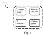
- Fig. 1 is a block system diagram showing an example aerosol generating apparatus.
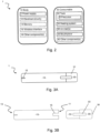
- Fig. 2 is a block system diagram showing an example implementation of the apparatus of Fig. 1, where the aerosol generating apparatus is configured to generate aerosol from a liquid precursor.
- Figs. 3A and 3B are schematic diagrams showing an example implementation of the apparatus of Fig. 2.
- Fig. 4 shows an aerosol-generating apparatus 100 according to the present disclosure. The view shown in Fig. 4 is a section view through section A-A annotated in Fig. 5.
- Fig. 5 shows the aerosol-generating apparatus 100 of Fig. 4. The view shown in Fig. 5 is a bottom view.
- Fig. 6 shows the aerosol-generating apparatus 100 of Fig. 4. The view shown in Fig. 6 is a section view through section B-B annotated in Fig. 7.
- Fig. 7 shows the aerosol-generating apparatus 100 of Fig. 4. The view shown in Fig. 7 is the bottom view shown in Fig. 5 rotated by 90 degrees.
- Fig. 8 shows the aerosol-generating apparatus 100 of Fig. 4 with the housing 110 removed. The view shown in Fig. 8 is a side view in the direction of the arrow labelled D1 in Fig. 10.
- Fig. 9 shows the aerosol-generating apparatus 100 of Fig. 4 with the housing 110 removed. The view shown in Fig. 9 is a side view in the direction of the arrow labelled D2 in Fig. 10.
- Fig. 10 shows the aerosol-generating apparatus 100 of Fig. 4. The view shown in Fig. 9 is a bottom view shown in Fig. 5 with the housing 110 removed.
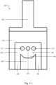
- Fig. 11 shows a aerosol-generating unit 220, the aerosol-generating unit 220 is an alternative embodiment of the aerosol-generating unit 120 where like features have been given like reference numerals.
DETAILED DESCRIPTION OF THE EMBODIMENTS
-
Before describing several examples implementing the present disclosure, it is to be understood that the present disclosure is not limited by specific construction details or process steps set forth in the following description and accompanying drawings. Rather, it will be apparent to those skilled in the art having the benefit of the present disclosure that the systems, apparatuses and/or methods described herein could be embodied differently and/or be practiced or carried out in various alternative ways.
-
Unless otherwise defined herein, scientific and technical terms used in connection with the presently disclosed inventive concept(s) shall have the meanings that are commonly understood by those of ordinary skill in the art, and known techniques and procedures may be performed according to conventional methods well known in the art and as described in various general and more specific references that may be cited and discussed in the present specification.
-
Any patents, published patent applications, and non-patent publications mentioned in the specification are hereby incorporated by reference in their entirety.
-
All examples implementing the present disclosure can be made and executed without undue experimentation in light of the present disclosure. While particular examples have been described, it will be apparent to those of skill in the art that variations may be applied to the systems, apparatus, and/or methods and in the steps or in the sequence of steps of the methods described herein without departing from the concept, spirit, and scope of the inventive concept(s). All such similar substitutions and modifications apparent to those skilled in the art are deemed to be within the spirit, scope, and concept of the inventive concept(s) as defined by the appended claims.
-
The use of the term "a" or "an" in the claims and/or the specification may mean "one," as well as "one or more," "at least one," and "one or more than one." As such, the terms "a," "an," and "the," as well as all singular terms, include plural referents unless the context clearly indicates otherwise. Likewise, plural terms shall include the singular unless otherwise required by context.
-
The use of the term "or" in the present disclosure (including the claims) is used to mean an inclusive "and/or" unless explicitly indicated to refer to alternatives only or unless the alternatives are mutually exclusive. For example, a condition "A or B" is satisfied by any of the following: A is true (or present) and B is false (or not present), A is false (or not present) and B is true (or present), and both A and B are true (or present).
-
As used in this specification and claim(s), the words "comprising, "having," "including," or "containing" (and any forms thereof, such as "comprise" and "comprises," "have" and "has," "includes" and "include," or "contains" and "contain," respectively) are inclusive or open-ended and do not exclude additional, unrecited elements or method steps.
-
Unless otherwise explicitly stated as incompatible, or the physics or otherwise of the embodiments, examples, or claims prevent such a combination, the features of examples disclosed herein, and of the claims, may be integrated together in any suitable arrangement, especially ones where there is a beneficial effect in doing so. This is not limited to only any specified benefit, and instead may arise from an "ex post facto" benefit. This is to say that the combination of features is not limited by the described forms, particularly the form (e.g. numbering) of example(s), embodiment(s), or dependency of claim(s). Moreover, this also applies to the phrase "in one embodiment," "according to an embodiment," and the like, which are merely a stylistic form of wording and are not to be construed as limiting the following features to a separate embodiment to all other instances of the same or similar wording. This is to say, a reference to 'an,' 'one,' or 'some' embodiment(s) may be a reference to any one or more, and/or all embodiments, or combination(s) thereof, disclosed. Also, similarly, the reference to "the" embodiment may not be limited to the immediately preceding embodiment. Further, all references to one or more embodiments or examples are to be construed as non-limiting to the claims.
-
The present disclosure may be better understood in view of the following explanations, wherein the terms used that are separated by "or" may be used interchangeably:
As used herein, an "aerosol generating apparatus" (or "electronic(e)-cigarette") may be an apparatus configured to deliver an aerosol to a user for inhalation by the user. The apparatus may additionally/alternatively be referred to as a "smoking substitute apparatus", if it is intended to be used instead of a conventional combustible smoking article. As used herein a combustible "smoking article" may refer to a cigarette, cigar, pipe or other article, that produces smoke (an aerosol comprising solid particulates and gas) via heating above the thermal decomposition temperature (typically by combustion and/or pyrolysis). An aerosol generated by the apparatus may comprise an aerosol with particle sizes of 0.2 to 7 microns, or less than 10 microns, or less than 7 microns. This particle size may be achieved by control of one or more of: heater temperature; cooling rate as the vapour condenses to an aerosol; flow properties including turbulence and velocity. The generation of aerosol by the aerosol generating apparatus may be controlled by an input device. The input device may be configured to be user-activated, and may for example include or take the form of an actuator (e.g. actuation button) and/or an airflow sensor.
-
Each occurrence of the aerosol generating apparatus being caused to generate aerosol for a period of time (which may be variable) may be referred to as an "activation" of the aerosol generating apparatus. The aerosol generating apparatus may be arranged to allow an amount of aerosol delivered to a user to be varied per activation (as opposed to delivering a fixed dose of aerosol), e.g. by activating an aerosol generating unit of the apparatus for a variable amount of time, e.g. based on the strength/duration of a draw of a user through a flow path of the apparatus (to replicate an effect of smoking a conventional combustible smoking article).
-
The aerosol generating apparatus may be portable. As used herein, the term "portable" may refer to the apparatus being for use when held by a user.
-
As used herein, an "aerosol generating system" may be a system that includes an aerosol generating apparatus and optionally other circuitry/components associated with the function of the apparatus, e.g. one or more external devices and/or one or more external components (here "external" is intended to mean external to the aerosol generating apparatus).
-
As used herein, an "external device" and "external component" may include one or more of a: a charging device, a mobile device (which may be connected to the aerosol generating apparatus, e.g. via a wireless or wired connection); a networked-based computer (e.g. a remote server); a cloud-based computer; any other server system.
-
An example aerosol generating system may be a system for managing an aerosol generating apparatus. Such a system may include, for example, a mobile device, a network server, as well as the aerosol generating apparatus.
-
As used herein, an "aerosol" may include a suspension of precursor, including as one or more of: solid particles; liquid droplets; gas. Said suspension may be in a gas including air. An aerosol herein may generally refer to/include a vapour. An aerosol may include one or more components of the precursor.
-
As used herein, a "precursor" may include one or more of a: liquid; solid; gel; loose leaf material; other substance. The precursor may be processed by an aerosol generating unit of an aerosol generating apparatus to generate an aerosol. The precursor may include one or more of: an active component; a carrier; a flavouring. The active component may include one or more of nicotine; caffeine; a cannabidiol oil; a non-pharmaceutical formulation, e.g. a formulation which is not for treatment of a disease or physiological malfunction of the human body. The active component may be carried by the carrier, which may be a liquid, including propylene glycol and/or glycerine. The term "flavouring" may refer to a component that provides a taste and/or a smell to the user. The flavouring may include one or more of: Ethylvanillin (vanilla); menthol, Isoamyl acetate (banana oil); or other. The precursor may include a substrate, e.g. reconstituted tobacco to carry one or more of the active component; a carrier; a flavouring.
-
As used herein, a "storage portion" may be a portion of the apparatus adapted to store the precursor. It may be implemented as fluid-holding reservoir or carrier for solid material depending on the implementation of the precursor as defined above.
-
As used herein, a "flow path" may refer to a path or enclosed passageway through an aerosol generating apparatus, e.g. for delivery of an aerosol to a user. The flow path may be arranged to receive aerosol from an aerosol generating unit. When referring to the flow path, upstream and downstream may be defined in respect of a direction of flow in the flow path, e.g. with an outlet being downstream of an inlet.
-
As used herein, a "delivery system" may be a system operative to deliver an aerosol to a user. The delivery system may include a mouthpiece and a flow path.
-
As used herein, a "flow" may refer to a flow in a flow path. A flow may include aerosol generated from the precursor. The flow may include air, which may be induced into the flow path via a puff by a user.
-
As used herein, a "puff" (or "inhale" or "draw") by a user may refer to expansion of lungs and/or oral cavity of a user to create a pressure reduction that induces flow through the flow path.
-
As used herein, an "aerosol generating unit" may refer to a device configured to generate an aerosol from a precursor. The aerosol generating unit may include a unit to generate a vapour directly from the precursor (e.g. a heating system or other system) or an aerosol directly from the precursor (e.g. an atomiser including an ultrasonic system, a flow expansion system operative to carry droplets of the precursor in the flow without using electrical energy or other system). A plurality of aerosol generating units to generate a plurality of aerosols (for example, from a plurality of different aerosol precursors) may be present in an aerosol generating apparatus.
-
As used herein, a "heating system" may refer to an arrangement of at least one heating element, which is operable to aerosolise a precursor once heated. The at least one heating element may be electrically resistive to produce heat from the flow of electrical current therethrough. The at least one heating element may be arranged as a susceptor to produce heat when penetrated by an alternating magnetic field. The heating system may be configured to heat a precursor to below 300 or 350 degrees C, including without combustion.
-
As used herein, a "consumable" may refer to a unit that includes a precursor. The consumable may include an aerosol generating unit, e.g. it may be arranged as a cartomizer. The consumable may include a mouthpiece. The consumable may include an information carrying medium. With liquid or gel implementations of the precursor, e.g. an e-liquid, the consumable may be referred to as a "capsule" or a "pod" or an "e-liquid consumable". The capsule/pod may include a storage portion, e.g. a reservoir or tank, for storage of the precursor. With solid material implementations of the precursor, e.g. tobacco or reconstituted tobacco formulation, the consumable may be referred to as a "stick" or "package" or "heat-not-burn consumable". In a heat-not-burn consumable, the mouthpiece may be implemented as a filter and the consumable may be arranged to carry the precursor. The consumable may be implemented as a dosage or pre-portioned amount of material, including a loose-leaf product. As used herein, an "information carrying medium" may include one or more arrangements for storage of information on any suitable medium. Examples include: a computer readable medium; a Radio Frequency Identification (RFID) transponder; codes encoding information, such as optical (e.g. a bar code or QR code) or mechanically read codes (e.g. a configuration of the absence or presents of cut-outs to encode a bit, through which pins or a reader may be inserted).
-
As used herein "heat-not-burn" (or "HNB" or "heated precursor") may refer to the heating of a precursor, typically tobacco, without combustion, or without substantial combustion (i.e. localised combustion may be experienced of limited portions of the precursor, including of less than 5% of the total volume).
-
Referring to Fig. 1, an example aerosol generating apparatus 1 includes a power supply 2, for supply of electrical energy. The apparatus 1 includes an aerosol generating unit 4 that is driven by the power supply 2. The power supply 2 may include an electric power supply in the form of a battery and/or an electrical connection to an external power source. The apparatus 1 includes a precursor 6, which in use is aerosolised by the aerosol generating unit 4 to generate an aerosol. The apparatus 2 includes a delivery system 8 for delivery of the aerosol to a user.
-
Electrical circuitry (not shown in figure 1) may be implemented to control the interoperability of the power supply 4 and aerosol generating unit 6.
-
In variant examples, which are not illustrated, the power supply 2 may be omitted since, e.g. an aerosol generating unit implemented as an atomiser with flow expansion may not require a power supply.
-
Fig. 2 shows an implementation of the apparatus 1 of Fig. 1, where the aerosol generating apparatus 1 is configured to generate aerosol from a liquid precursor.
-
In this example, the apparatus 1 includes a device body 10 and a consumable 30.
-
In this example, the body 10 includes the power supply 4. The body may additionally include any one or more of electrical circuitry 12, a memory 14, a wireless interface 16, one or more other components 18.
-
The electrical circuitry 12 may include a processing resource for controlling one or more operations of the body 10 and consumable 30, e.g. based on instructions stored in the memory 14.
-
The wireless interface 16 may be configured to communicate wirelessly with an external (e.g. mobile) device, e.g. via Bluetooth.
-
The other component(s) 18 may include one or more user interface devices configured to convey information to a user and/or a charging port, for example (see e.g. Fig. 3).
-
The consumable 30 includes a storage portion implemented here as a tank 32 which stores the liquid precursor 6 (e.g. e-liquid). The consumable 30 also includes a heating system 34, one or more air inlets 36, and a mouthpiece 38. The consumable 30 may include one or more other components 40.
-
The body 10 and consumable 30 may each include a respective electrical interface (not shown) to provide an electrical connection between one or more components of the body 10 with one or more components of the consumable 30. In this way, electrical power can be supplied to components (e.g. the heating system 34) of the consumable 30, without the consumable 30 needing to have its own power supply.
-
In use, a user may activate the aerosol generating apparatus 1 when inhaling through the mouthpiece 38, i.e. when performing a puff. The puff, performed by the user, may initiate a flow through a flow path in the consumable 30 which extends from the air inlet(s) 34 to the mouthpiece 38 via a region in proximity to the heating system 34.
-
Activation of the aerosol generating apparatus 1 may be initiated, for example, by an airflow sensor in the body 10 which detects airflow in the aerosol generating apparatus 1 (e.g. caused by a user inhaling through the mouthpiece), or by actuation of an actuator included in the body 10. Upon activation, the electrical circuitry 12 (e.g. under control of the processing resource) may supply electrical energy from the power supply 2 to the heating system 34 which may cause the heating system 32 to heat liquid precursor 6 drawn from the tank to produce an aerosol which is carried by the flow out of the mouthpiece 38.
-
In some examples, the heating system 34 may include a heating filament and a wick, wherein a first portion of the wick extends into the tank 32 in order to draw liquid precursor 6 out from the tank 32, wherein the heating filament coils around a second portion of the wick located outside the tank 32. The heating filament may be configured to heat up liquid precursor 6 drawn out of the tank 32 by the wick to produce the aerosol.
-
In this example, the aerosol generating unit 4 is provided by the above-described heating system 34 and the delivery system 8 is provided by the above-described flow path and mouthpiece 38. In variant embodiments (not shown), any one or more of the precursor 6, heating system 34, air inlet(s) 36 and mouthpiece 38, may be included in the body 10. For example, the mouthpiece 36 may be included in the body 10 with the precursor 6 and heating system 32 arranged as a separable cartomizer.
-
Figs. 3A and 3B show an example implementation of the aerosol generating apparatus 1 of Fig. 2. In this example, the consumable 30 is implemented as a capsule/pod, which is shown in Fig. 3A as being physically coupled to the body 10, and is shown in Fig. 3B as being decoupled from the body 10.
-
In this example, the body 10 and the consumable 30 are configured to be physically coupled together by pushing the consumable 30 into an aperture in a top end 11 the body 10, with the consumable 30 being retained in the aperture via an interference fit.
-
In other examples (not shown), the body 10 and the consumable 30 could be physically coupled together in other ways, e.g. by screwing one onto the other, through a bayonet fitting, or through a snap engagement mechanism, for example.
-
The body 10 also includes a charging port (not shown) at a bottom end 13 of the body 10. The body 10 also includes a user interface device configured to convey information to a user. Here, the user interface device is implemented as a light 15, which may e.g. be configured to illuminate when the apparatus 1 is activated. Other user interface devices are possible, e.g. to convey information haptically or audibly to a user.
-
In this example, the consumable 30 has an opaque cap 31, a translucent tank 32 and a translucent window 33. When the consumable 30 is physically coupled to the body 10 as shown in Fig. 3a, only the cap 31 and window 33 can be seen, with the tank 32 being obscured from view by the body 10. The body 10 includes a slot 15 to accommodate the window 33. The window 33 is configured to allow the amount of liquid precursor 6 in the tank 32 to be visually assessed, even when the consumable 30 is physically coupled to the body 10.
-
Figs. 4 to 10, show an aerosol-generating apparatus 100 according to the present disclosure. The bold arrows in Figs. 4 and 6 indicate the direction of airflow through the aerosol-generating apparatus 100 during normal use (i.e. when an aerosol is being generated for inhalation by a user of the aerosol-generating apparatus).
-
The aerosol-generating apparatus 100 comprises an aerosol-generating unit 120 having a longitudinal central axis 105. The aerosol-generating unit 120 is fully circumferentially surrounded by a housing 110 in the longitudinal direction (i.e. a direction of the longitudinal axis 105). The housing 110 is tubular and extends in the longitudinal direction and conforms with a portion of the aerosol-generating unit 120. The aerosol-generating unit 120 defines an internal heating chamber 130 in which liquid aerosol precursor is aerosolised into an aerosol by a heating system 126 for inhalation by a user.
-
The aerosol-generating unit 120 includes a base part 122, a central part 123 and a top part 124 that respectively delimit a bottom portion 132 of the heating chamber 130, a central portion 133 of the heating chamber 130 and a top portion 134 of the heating chamber 130. The heating system 126 is for aerosolising liquid aerosol precursor and is positioned between the base part 122 and the top part 124 of the aerosol-generating unit 120. The top part 124 of the aerosol-generating unit 120 defines an aerosol-generating unit air outlet 136 from the heating chamber 130 such that aerosol generated by the heating system 126 can pass through the aerosol-generating unit air outlet 136 for inhalation by a user. The top part 124 of the aerosol-generating unit 120 is connected to the base part 122 of the aerosol-generating unit 120 via the central part 123 of the aerosol-generating unit 120. The central part 123 of the aerosol-generating unit 120 includes a first side and a second side. The first side of the central part 123 is opposite the second side of the central part 123. The top part 124 of the aerosol-generating unit 120 converges uniformly towards the aerosol-generating unit air outlet 136. The base part 122 of the aerosol-generating unit 120 includes a liquid collection unit 128 in the form of a cavity. The liquid collection unit 128 is located adjacent the bottom portion 132 of the heating chamber 130 such that any liquid aerosol precursor dripping from the heating system may be collected in the liquid collection unit 128. In alternative embodiments, the liquid collection unit may be a portion of absorbent material such as cotton, sponge and/or felt.
-
A first aerosol-generating unit air inlet 171, a second aerosol-generating unit air inlet 172 and a third aerosol-generating unit air inlet 173 are located through the first side of the central part 123 of the aerosol-generating unit 120. A fourth aerosol-generating unit air inlet 174, a fifth aerosol-generating unit air inlet 175 and a sixth aerosol-generating unit air inlet 176 are located through the second side of the central part 123 of the aerosol-generating unit 120. These are shown in Figs. 8 and 9. The aerosol-generating unit air inlets 171, 172, 173, 174, 175, 176 are located between the base part 122 of the aerosol-generating unit 120 and the top part 124 of the aerosol-generating unit 120. The aerosol-generating unit air inlets 171, 172, 173, 174, 175, 176 are located between the heating system 126 and the base part 122 of the aerosol-generating unit 120. The aerosol-generating unit air inlets 171, 172, 173 on the first side of the central part 123 of the aerosol-generating unit 120 face the aerosol-generating unit air inlets 174, 175, 176 on the second side of the central part 123 of the aerosol-generating unit 120. The aerosol-generating unit air inlets 171, 172, 173, 174, 175, 176 supply air to the heating chamber 130 to facilitate aerosol generating by the heating system 126. The aerosol-generating unit air inlets 171, 172, 173 on the first side of the central part 123 of the aerosol-generating unit 120 may be referred to as a first set of aerosol-generating unit air inlets. The first set of aerosol-generating unit air inlets 171, 172, 173 are arranged in a first line (i.e. form a first linear array). The aerosol-generating unit air inlets 174, 175, 176 on the second side of the central part 123 of the aerosol-generating unit 120 may be referred to as a second set of aerosol-generating unit air inlets. The second set of aerosol-generating unit air inlets 174, 175, 176 are arranged in a second line (i.e. a second linear array). Both the first line and the second line are perpendicular to the longitudinal axis 105. The first set of aerosol-generating unit air inlets 171, 172, 173 are evenly distributed along the first line such that there is an equal distance between the first aerosol-generating unit air inlet 171 and the second aerosol-generating unit air inlet 172 as well as between the second aerosol-generating unit air inlet 172 and the third aerosol-generating unit air inlet 173. The second set of aerosol-generating unit air inlets 174, 175, 176 are evenly distributed along the second line such that there is an equal distance between the fourth aerosol-generating unit air inlet 174 and the fifth aerosol-generating unit air inlet 175 as well as between the fifth aerosol-generating unit air inlet 175 and the sixth aerosol-generating unit air inlet 176. The first set of aerosol-generating unit air inlets 171, 172, 173 are located within a first outwardly-facing planar surface 125 of the aerosol-generating unit. The second set of aerosol-generating unit air inlets 174, 175, 176 are located within a second outwardly-facing planar surface 127 of the aerosol-generating unit. The first outwardly-facing planar surface 125 is geometrically similar to and parallel to the second outwardly-facing planar surface 127 as illustrated in Fig. 8 and Fig. 9. The first outwardly-facing planar surface 125 is rectangular. The second outwardly-facing planar surface 127 is rectangular.
-
The housing 110 and the aerosol-generating unit 120 jointly delimit a first inlet air passage 140 and a second inlet air passage 142. The first inlet air passage 140 is positioned opposite the second inlet air passage 142 relative to the longitudinal axis 105. The first inlet air passage 140 and the second inlet air passage 142 are both located between the aerosol-generating unit 120 and the housing 110 such that air can flow from the external environment at a base 101 of the aerosol-generating apparatus 100 along the inlet air passages 140, 142 through the aerosol-generating unit air inlets 171, 172, 173, 174, 175, 176 and into the heating chamber 130. The first inlet air passage 140 is configured to supply air to the aerosol-generating unit air inlets 171, 172, 173 on the first side of the aerosol-generating unit 120 and the second inlet air passage 142 is configured to supply air to the aerosol-generating unit air inlets 174, 175, 176 on the second side of the aerosol-generating unit 120.
-
Fig. 4 shows a cross-section of the aerosol-generating apparatus 100 through section A-A annotated on Fig. 5. Fig. 6 shows a cross-section of the aerosol-generating apparatus 100 through section B-B annotated on Fig. 7. Fig. 8 shows a side view of the aerosol-generating apparatus 100 with the housing 110 removed as viewed in the direction of the arrow labelled D1 in Fig. 10. Fig. 9 shows a side view of the aerosol-generating apparatus 100 with the housing 110 removed as viewed in the direction of the arrow labelled D2 in Fig. 10. Fig. 5 and Fig. 7 show the base 101 of the aerosol-generating apparatus 100 in different orientations. Fig. 10 shows the same view as Fig. 7 but with the housing 110 removed.
-
The heating system 126 includes a substantially planar heating element. The heating element is porous such that it also acts as a wick (e.g. it can store liquid aerosol precursor e.g. via capillary action). The plane of the heating element is perpendicular to the longitudinal axis 105. The heating element spans the heating chamber 130 in a plane normal to the longitudinal axis 105. The aerosol-generating apparatus 100 includes a tank 180. The tank 180 is jointly delimited by the housing 110 and an aerosol delivery structure 150. The heating element 126 is supplied with liquid aerosol precursor from the tank 180 via a first delivery conduit 181 and a second delivery conduit 182. The first and second delivery conduits 181, 182 are jointly delimited by the aerosol delivery structure 150. The liquid aerosol precursor is supplied to the heating element 126 via capillary action along the first and second delivery conduits 181, 182.
-
The aerosol-generating unit 120 includes a first electrode receiving cavity 160 for receiving a first electrode and a second electrode receiving cavity 162 for receiving a second electrode such that current can be supplied to the heating element 126. The first electrode receiving cavity 160 is located on the opposite side of the aerosol-generating unit 120 to the second electrode receiving cavity 162 relative to the longitudinal axis 105. The first and second electrode receiving cavities 160, 162 are substantially cylindrical and extend in the longitudinal direction of the aerosol-generating apparatus 100. The first and second electrode receiving cavities 160, 162 terminate at the heating element such that current can be supplied to the heating element.
-
Figs. 5, 7 and 10 show bottom views of the aerosol-generating apparatus 100. Fig. 5 shows the same view as Fig. 7 but rotated 90 degrees. Fig. 10 shows the same view as Fig. 7 but with the housing 110 removed. The part of the aerosol-generating apparatus 100 shown in Figs. 5 7 and 10 may be understood to be the base 101 of the aerosol-generating apparatus 100 as labelled in Figs. 4, 6, 8 and 9. The housing 110 fully surrounds the aerosol-generating unit 120 in the circumferential direction. The entrance to the first electrode receiving cavity 160 is located in the aerosol-generating unit 120 proximal the housing 110. The entrance to the second electrode receiving cavity 162 is located in the aerosol-generating unit 120 proximal the housing 110. The entrance to the first inlet air passage 140 is located on the opposite side of the aerosol-generating unit 120 to the entrance of the second inlet air passage 142 relative to the longitudinal axis 105. The normal to the plane defined by the perimeter of the first inlet air passage 140 is parallel to the longitudinal axis 105. The normal to the plane defined by the perimeter of the second inlet air passage 142 is parallel to the longitudinal axis 105. The first set of aerosol-generating unit air inlets 171, 172, 173 is located distal to the entrance of the inlet air passage 140. The second set of aerosol-generating unit air inlets 174, 175, 176 is located distal to the entrance of the second inlet air passage 142.
-
Fig. 11 shows an alternative embodiment of the aerosol-generating unit 120 of the aerosol generating device 100. The aerosol-generating unit 220 may be implemented in an aerosol-generating apparatus 200 (not shown) that is otherwise identical to the aerosol-generating apparatus 100. The alternative aerosol-generating unit 220 is similar to the aerosol-generating unit 120 of Figs. 4 to 10 but includes a projection 290 extending from the outwardly-facing planar surface 225 of the aerosol-generating unit 220. The projection 290 includes a sump 292. The sump 292 is adjacent (below) the first, second and third aerosol-generating unit air inlets 271, 272, 273. A first sub-inlet air passage 244 and second sub-inlet air passage 246 are jointly delimited by the projection 290, the aerosol-generating unit 220 and the housing 210 when the aerosol-generating unit 220 is inserted into the housing 210 (not shown). When the aerosol-generating unit 220 is inserted into the housing 210, the projection 290 spaces the housing 210 from the outwardly-facing planar surface 225 of the aerosol-generating unit 220. The aerosol-generating unit 220 is shown connected to an aerosol delivery structure 250. The aerosol delivery structure 250 is identical to the aerosol delivery structure 150 of Figs. 4 to 10. It should be understood that the aerosol-generating unit 220 may be interchanged with the aerosol-generating unit 120 in the aerosol-generating apparatus 100 of Figs. 4 to 10.