EP4529778A1 - Method and unit for inspecting multisegment rod-shaped articles - Google Patents
Method and unit for inspecting multisegment rod-shaped articles Download PDFInfo
- Publication number
- EP4529778A1 EP4529778A1 EP24197703.2A EP24197703A EP4529778A1 EP 4529778 A1 EP4529778 A1 EP 4529778A1 EP 24197703 A EP24197703 A EP 24197703A EP 4529778 A1 EP4529778 A1 EP 4529778A1
- Authority
- EP
- European Patent Office
- Prior art keywords
- articles
- light guide
- unit
- light
- article
- Prior art date
- Legal status (The legal status is an assumption and is not a legal conclusion. Google has not performed a legal analysis and makes no representation as to the accuracy of the status listed.)
- Granted
Links
Images



Classifications
-
- A—HUMAN NECESSITIES
- A24—TOBACCO; CIGARS; CIGARETTES; SIMULATED SMOKING DEVICES; SMOKERS' REQUISITES
- A24C—MACHINES FOR MAKING CIGARS OR CIGARETTES
- A24C5/00—Making cigarettes; Making tipping materials for, or attaching filters or mouthpieces to, cigars or cigarettes
- A24C5/32—Separating, ordering, counting or examining cigarettes; Regulating the feeding of tobacco according to rod or cigarette condition
- A24C5/34—Examining cigarettes or the rod, e.g. for regulating the feeding of tobacco; Removing defective cigarettes
- A24C5/3412—Examining cigarettes or the rod, e.g. for regulating the feeding of tobacco; Removing defective cigarettes by means of light, radiation or electrostatic fields
-
- A—HUMAN NECESSITIES
- A24—TOBACCO; CIGARS; CIGARETTES; SIMULATED SMOKING DEVICES; SMOKERS' REQUISITES
- A24D—CIGARS; CIGARETTES; TOBACCO SMOKE FILTERS; MOUTHPIECES OF CIGARS OR CIGARETTES; MANUFACTURE OF TOBACCO SMOKE FILTERS OR MOUTHPIECES
- A24D1/00—Cigars; Cigarettes
- A24D1/20—Cigarettes specially adapted for simulated smoking devices
Definitions
- This invention addresses the tobacco industry and relates to a unit and method for inspecting multisegment articles.
- the prior art teaches that a plurality or mass of articles can be transferred along a processing or transfer path by means of an indirect guide, that is to say, by means of a bottom guide (a conveyor belt, a bottom wall of a tray, a flexible or movable wall for filling a hopper, or other means) supporting the articles, where the articles interact with each other by frictional contact and gravitational force.
- a bottom guide a conveyor belt, a bottom wall of a tray, a flexible or movable wall for filling a hopper, or other means
- the articles which are not directly supported by the bottom guide are susceptible of uncontrolled alteration of their orientation, with the risk of one or more articles rotating about directions which are inclined relative to their axes.
- the purpose of the invention is thus to identify the orientation adopted by each article in a group of mass of articles in order to identify whether the article is oriented in the correct direction or in the opposite direction. Indeed, when a mass of articles is being moved or when spaces such as hoppers or trays are being filled, one or more articles may be incorrectly oriented, making them unsuitable for subsequent packing.
- More recently developed smoking articles can be made with a filter segment at a first end and closing segment, or "plug" at the other end, between which there are several other kinds of segments, such as, for example, tubular segments, an aerosol generating segment, and so on.
- Such articles are suitable, for example, for forming an aerosol by heating, more particularly, by induction heating using a device in which the article is partly inserted.
- the ends of such articles are visually identical: for example, they are white. That is because the materials the filters and closing segments are made of are visually similar. These materials are selected, for example, from the group comprising acetate, monoacetate or crimped paper.
- the filter segment and the closing segment although they differ in axial length and are made of different materials, are similar in outward appearance.
- that application discloses positioning a lighting device, configured to emit a light beam in the direction of a lateral surface of at least one article, and an evaluation device, configured to receive the emitted light at an end surface of the irradiated article (and generated by the light beam itself).
- the intensity of the light that emerges from the end being examined differs and this information can be used to identify the way the article in the group of articles is oriented.
- Such a method has the disadvantage of not ensuring adequate precision in identifying the orientation of rod-shaped articles, in particular in the case of articles arranged in more than one row.
- the Applicant has found that inspecting superposed rows of articles according to the above-mentioned solution is subject to errors because the light beam emitted by the lighting device irradiates only the lateral surfaces of articles of a row facing the lighting device, while irradiation of the inner rows is more attenuated. As a result of the attenuated light, inspection of the articles in the inner rows is less effective. Obviously, duplicating the device on the other side could, ideally, partly make up for this drawback but it would mean creating a more complex and expensive structure which would in any case suffer from the same drawbacks caused by the light being attenuated in the case of additional inner rows.
- the aim of this invention is therefore to provide a unit and a method for inspecting multisegment articles and capable of ensuring an effective process of identifying the orientation of an article.
- Another aim of this invention is to provide a unit and a method for inspecting multisegment articles and capable of attaining a high level of reliability by greatly limiting inspection errors, in particular with reference to applications which involve inspecting articles which are arranged in superposed rows.
- a further aim of this invention is to provide a unit and a method for inspecting multisegment articles and capable of simplifying the structure needed for inspection.
- the Applicant has found that by using a light guide, positioned to surround a group of articles, arranged in parallel rows, around the respective lateral surfaces, and irradiating the articles with a light beam incident upon the light guiding device, it is possible not only to illuminate the articles of the first row directly but also to convey some of the light around the articles and direct it towards the row underneath, thus obtaining precise and reliable information regarding the orientation of each article.
- the light guide allows conveying the light from a row located proximally to a point where the light beam is emitted to a row located distally to the point where the light beam is emitted.
- the numeral 100 denotes in its entirety a rod-shaped multisegment article
- the numeral 1 denotes in its entirety a unit for inspecting articles 100 (and represented schematically and only partially in the accompanying drawings) according to this invention.
- rod-shaped multisegment article is used to mean a rod-shaped article divided into several segments and defining, or intended to define, a smoking article, in particular intended to form a smoking article suitable for generating an aerosol by heating, preferably by heat generated externally by electromagnetic induction or by conduction.
- the article 100 extends along a respective axis of extension X between opposite end surfaces 100a and 100b and comprises a lateral surface 100c extending between the end surfaces 100a and 100b.
- the article 100 is divided at least into one filter segment 101, one closing segment 102 and, between the filter segment 101 and the closing segment 102, other segments responsible for forming and treating the aerosol.
- These other segments may comprise, preferably, a segment 103 of material suitable for generating an aerosol by heating, and at least one tubular segment 104.
- the filter segment 101, the closing segment 102, the segment 103 and the tubular segment 104 are disposed in sequence along the axis of extension X.
- the filter segment 101 and the closing segment 102 are intended to define respectively a first end surface 100a of the article 100 and a second end surface 100b of the article 100.
- the segment 103 is adjacent to the closing segment 102, while the at least one tubular segment 104 is placed between the segment 103 and the filter segment 101.
- the segment 103 may contain a generic material suitable for releasing an aerosol when heated, for example strips of tobacco or containing a tobacco flavouring, or a crimped sheet of tobacco or containing a tobacco flavouring.
- the at least one tubular segment 104 may act as a spacing element between the filter element 101 and the segment 103, and/or as a cooling element, suitable for lowering the temperature of the aerosol as a result of the user inhaling or of the segment 103 itself being heated.
- tubular segment 104 is a spacer and is followed by a cooling segment with a non-tubular structure.
- tubular segment 104 is divided into a pair of pieces 104a, 104b, suitable for performing, respectively, the function of spacing element and the function of cooling element.
- the filter segment 101 and the closing segment 102 of the same article 100 have different axial lengths, that is to say, they differ in extent along the axis of extension X of the article 100.
- the filter segment 101 and the closing segment 102 are made of different materials, in particular selected between acetate, monoacetate and crimped paper.
- the filter segment 101 and the closing segment 102 may be made of acetate and crimped paper, respectively, or of monoacetate and acetate, respectively.
- the filter segment 101 and the closing segment 102 have the same outward appearance, in particular, they have the same colour, the same hue and the same surface structure. In particular, they have an uninterrupted end surface, preferably smooth, and are white in colour. Thus, it is not possible to visually distinguish between the filter segment 101 and the closing segment 102, that is to say, between the first end surface 100a and the second end surface 100b based on aesthetic parameters.
- the invention involves arranging a plurality of articles 100 in mutually juxtaposed fashion with the respective axes of extension X parallel to each other, preferably predetermined in number and distribution suitable for defining the contents of a standard packet, or alternatively, in a mass flow configuration (moving on a belt, downwards in a hopper) or, in yet another alternative, in a mass stored in trays or containers.
- the lateral surface 100c of at least one article 100 is irradiated with a light beam F, which is conveyed around the plurality of articles 100 by a light guide 500 and, thanks to the fact that the closing segment 102 and the filter segment 101 have different axial lengths, detecting the light emitted frontally by the articles themselves allows obtaining information relating to the orientation of the irradiated article 100.
- the absorption of the light beam F along the article 100 (that is, from the lateral surface 100c to each of the end surfaces 100a, 100b) is different according to the length of the end segment 100a, 100b, hence according to the orientation of the article 100.
- orientation is meant the spatial position of the article 100 along its axis of extension X.
- the article 100 has two possible orientations in two opposite directions.
- the unit 1 is positioned along a feed direction of the articles 100 and is stationary.
- the articles 100 may be at least temporarily stationary while the unit 1 is moved.
- both the articles 100 and the unit 1 are moved.
- the articles 100 are subjected to indirect guiding (during at least one step in which they are conveyed after they have been made), where such indirect guiding may be at the unit 1 or upstream of it.
- indirect guiding may be at the unit 1 or upstream of it.
- indirect guiding is used to mean a flow of articles 100, where only a small number of the articles is directly in contact with a guiding part, such as, for example, a conveyor belt or a movable wall.
- indirect guiding may be the result of gravity feed inside a hopper or constrained guiding of a main (bottom) layer of articles 100, which, by moving the main layer causes the peripheral (upper) layers of articles 100 on top of the main layer to move. This occurs, for example, in a mass flow (mass stream) when articles are being transported in a container or tray.
- mass flow mass flow
- indirect guiding is indicated as an operative condition such as, potentially, to cause misalignment of one or more articles 100 leading to them being incorrectly oriented.
- the unit 1 comprises at least one supporting element 2, suitable for receiving a plurality of articles 100, for example from a hopper (not illustrated in the accompanying drawings), and for supporting the plurality of articles 100, positioned with their respective axes parallel to each other.
- the supporting element 2 is movable and has a connecting portion 2', suitable for connecting the supporting element 2 to a movement means such as a chain, a belt or other closed-loop conveyor.
- a movement means such as a chain, a belt or other closed-loop conveyor.
- the supporting element 2 is configured to support a plurality of articles 100 arranged along a plurality of superposed rows (two rows in the embodiment illustrated) so that the articles 100 of different rows have their respective axes of extension X parallel to each other.
- the supporting element 2 is configured to support a plurality of articles 100, defined by a group of articles 100 predetermined in number and distribution suitable for defining the contents of a standard packet to be made, and the unit 1 is preferably located upstream of a packing station.
- the support 2 may therefore be a cleat of a cleated conveyor which feeds the articles from a hopper to a packing machine.
- the supporting element 2 has at least one containment compartment V for a plurality of articles 100.
- the supporting element 2 has two containment compartments V which are juxtaposed and separated from each other by a middle wall 20.
- Each containment compartment V is intended to contain a respective plurality of articles 100.
- the supporting element 2 is suitable for supporting the articles 100 in such a way as to expose one of the end surfaces 100a or 100b, or both, of each article 100.
- the invention comprises first of all irradiating at least one article 100 with a light beam F, as shown in Figures 3 and 4 .
- the light beam F is preferably a laser beam.
- the light beam F is incident upon the lateral surface 100c of at least one article 100.
- irradiating the lateral surface 100c makes it possible, using a specific device, to detect a light intensity diffused by an end surface 100a, 100b of the article 100 and, thanks to that intensity, to derive information relating to an orientation of the article 100.
- the filter segment 101, defining the first end 100a, and the closing segment 102, defining the second end 100b because they differ in axial length, cause the light beam F to be absorbed differently along each article 100 (that is to say, along the axis X), corresponding to different light intensities diffused by each end surface 100a, 100b.
- the light beam F is emitted along a direction or plane of emission E (schematically illustrated in Figure 4 ) incident upon the lateral surface 100c of at least one article 100 and having a predetermined angle, preferably perpendicular, to a positioning plane of the irradiated lateral surface 100.
- the unit 1 comprises at least one emitting device 3 positioned to face the supporting element 2 and configured to emit the light beam F along the emitting direction E.
- the emitting device 3 comprises a laser emitter, configured to emit a laser light.
- a similar emitter 3, configured to emit the laser beam F, may be positioned on the opposite side of the supporting element 2.
- the luminous radiation emitted by the end surface 100a, 100b is received and measured and from that radiation, at least one signal identifying the light intensity of the radiation is generated.
- the signal generated is then processed to obtain information relating to the orientation of each article 100 of the plurality of articles 100.
- the different axial extents of the filter segment 101 and of the closing segment 102 allows obtaining an identification signal associated with the first end surface 100a (defined by the filter segment 101) different from the identification signal associated with the second end surface 100b (defined by the closing segment 102).
- the emitter 3 is configured to emit a light beam F at a predefined distance from the second end surface 100b (defined by the closing segment 102) and such that, if the article 100 is well oriented (that is to say, is not incorrectly oriented), the light beam F is directed towards the segment 103, which may contain a generic material suitable for forming an aerosol when heated, for example, strips of tobacco or containing a tobacco flavouring, or a crimped sheet of tobacco or containing a tobacco flavouring.
- the segment 103 unlike the other segments 101, 102 and 104 which allow at least partly diffusing the light beam F along the article 100, is capable of absorbing substantially all of the light beam F, thus interrupting its flow along the article 100; as a result, if the article 100 is incorrectly oriented, the light beam F is directed towards the filter segment 101 and/or towards the tubular segment 104 which do allow the light beam F to be diffused along the article 100.
- the different capacities of the segment 103, of the filter segment 101 and of the tubular segment 104 to absorb the light beam F thus allows obtaining an identification signal associated with the first end surface 100a (defined by the filter segment 101) different from the identification signal associated with the second end surface 100b (defined by the closing segment 102).
- Processing the identification signal thus makes it possible to distinguish the end surfaces 100a, 100b, hence to obtain reliable information relating to the orientation of the article 100.
- the step of generating the identification signal is carried out by optical inspection, performed along a detecting direction R incident upon the end surface 100a, 100b to be detected.
- the detecting direction R is perpendicular to the positioning plane of the end surface 100a, 100b to be detected.
- the unit 1 comprises at least one detecting device 4, configured to capture along the detecting direction R the light diffused by the end surface 100a, 100b and generated by the light beam F. Therefore, the detecting device 4 is positioned to face the supporting element 2.
- the detecting device 4 is also configured to generate a signal identifying the intensity of the captured light.
- the identification signal comprises, for example, one or more digital images of the end surfaces 100a, 100b detected.
- the unit 1 also comprises a control unit 5, configured to receive and process the signal generated by the detecting device 4.
- control unit 5 is connected or connectable to the detecting device 4, for example, by specific wiring, by a wireless connection or other types of connections.
- control unit 5 is configured to receive the identification signal (for example, the aforesaid digital images) and to process the identification signal to obtain information relating to the orientation of each article 100, in particular relating to the position of the end surfaces 100a, 100b.
- the unit 1 comprises at least one light guide 500, at least partly surrounding the containment compartment V of the supporting element 2.
- the invention comprises a step of inserting the plurality of articles 100 into the cavity "A" of the light guide 500 so that the light guide 500 at least partly surrounds the plurality of articles 100.
- the light guide 500 is configured to receive the light produced by the light beam F and to convey some of the light around the plurality of articles 100 positioned in the containment compartment V from a first zone of the plurality of articles 100 confronting the emitting device 3 towards a second zone of the plurality of articles 100 opposite the first zone.
- the light guide 500 is suitable for receiving the light beam F and conveying some of the light produced by it around the containment compartment V so as to irradiate the plurality of articles 100 contained therein.
- using the light guide 500 advantageously allows collecting the light produced by the light beam F, propagating along the emitting direction E and not directed towards the articles 100 of the upper row, along an at least partly closed path surrounding the articles 100, in particular around the respective axes of extension X, allowing the lateral surfaces 100c not directly exposed to the light beam F to be irradiated.
- the expression "lateral surfaces 100c not directly exposed to the light beam F” denotes the lateral surfaces 100c of articles 100 disposed in such a way that other articles 100, in particular, those of the row underneath, mask the light beam F from them.
- each article 100 not directly exposed to the light beam F cannot be irradiated directly, nevertheless, thanks to the light guide 500, the light produced by the light beam F can be diverted so that those articles 100 can also be irradiated.
- the light guide 500 thus allows obtaining an identification signal associated with the filter segment 101 and an identification signal associated with the closing segment 102 which are more easily distinguishable from each other.
- the emitting direction E is incident upon the light guide 500.
- the emitting direction E is at an angle such as to allow an inside surface 501 of the light guide 500, facing towards the articles 100, to totally reflect a part of the light beam F so as to convey the maximum amount of remaining light (residual at the fraction that reaches the upper row of articles) around the containment compartment V, hence around the articles 100.
- the light guide 500 comprises a first base wall 500a, a second base wall 500b and at least one side wall 500c positioned to join the base walls 500a, 500b.
- the supporting element 2 is configured to receive articles from a hopper (not shown in the accompanying drawings) and the first base wall 500a is a top wall, facing towards the hopper, while the second base wall 500b is a bottom wall, opposite the top wall 500a.
- first base wall 500a is a top wall, facing towards the hopper
- second base wall 500b is a bottom wall, opposite the top wall 500a.
- top and bottom should be understood as being non-limiting in that embodiments where the emitting device 3 positioned under or laterally of the supporting element 2 remain within the scope of the invention.
- the light guide 500 has at least one cavity A which is at least partly delimited by the base walls 500a, 500b and the side wall 500c.
- the cavity A is open at the front and back, that is to say, it is a through cavity, and is suitable for at least partly defining the containment compartment V of the supporting element 2 and for receiving the plurality of articles 100.
- the light guide 500 is integrated preferably removably in the supporting element 2.
- the light guide 500 is made in the form of a contoured slab-like element
- the supporting element 2 is preferably defined by a cleat of a cleated conveyor and comprises a slot 2a in which the light guide device 500 is inserted or insertable, preferably removably, in particular along a direction perpendicular to the axis of extension X.
- the light guide 500 is removable from the supporting element 2, allowing it to be replaced when worn or for retrofitting on existing supporting elements 2 (which may be machined to make the aforementioned slot 2a, for example by milling).
- the light guide 500 is positioned to confront the emitting device 3 to receive the light beam F at the first base wall 500a and is configured to convey the received light from the first base wall 500a to the second base wall 500b and around the cavity A; that way, the light conveyed around the plurality of articles 100 is directed from a first zone (proximal to the first base wall 500a) to a second zone (proximal to the second base wall 500b) of the plurality of articles 100.
- the first base wall 500a in use, is at least partly traversed by the light beam F) so that a first part of the light beam F reaches the first zone of the plurality of articles 100 and a second part of the light beam F remains trapped in the light guide 500 and is guided by it towards the second zone of the plurality of articles 100.
- a first row of articles 100 which confronts the emitting device 3 is, in use, irradiated by the first part of the light beam F through the first base wall 500a, while a second row of articles 100 which, in use, is positioned in such a way as to be masked by the first row, is irradiated by the second part of the light beam F, guided by the light guide 500.
- the first wall 500a has a break zone, extending for the whole length of the light guide 500 along the axis of extension X and preferably located in a central zone of the first base wall 500a.
- the light guide 500 is made as a single block.
- the light guide 500 is made of a transparent material, preferably glass, polycarbonate or Plexiglas.
- the light guide 500 is made in the form of an insert, made of material transparent to the light beam, insertable in the containment compartment and being, in particular, extractable.
- At least one inside wall 501 of the light guide 500, preferably each inside wall 501, facing towards the containment compartment V is aligned flush with the corresponding inside wall of the supporting element 2 facing towards the containment compartment V.
- the containment compartment V of the supporting element 2 and the cavity A of the light guide 500 are substantially identical and superposable.
- the light guide 500 in a cross section transverse to the axis of extension X is substantially identical to the supporting element 2.
- the light guide 500 comprises a plurality of cavities A, each corresponding to, and associated or associable with, a respective containment compartment V.
- the unit 1 comprises a respective plurality of light guides (500), each light guide (500) being associated with a respective containment compartment V to surround the respective plurality of articles 100.
- the light guide 500 defines a cleat of a cleated conveyor, hence the supporting element 2.
- the unit 1 comprises a reflective element 600 associated with the light guide 500 at least in the second zone of the plurality of articles 100, preferably at the second base wall 500b.
- the reflective element 600 is located at a position opposite the containment compartment V so that the light conveyed by the light guide 500 is reflected towards the articles 100.
- the reflective element 600 allows the plurality of articles 100 to be irradiated better so that the information regarding an orientation of the articles 100 is more reliable.
- the reflective element 600 is positioned directly in contact with the light guide 500.
- the reflective element 600 is positioned at the second base wall 500b and at the side wall 500c of the light guide 500.
- the reflective element 600 comprises a strip, preferably flexible, made of a material selected between foil and paper, preferably white paper.
- the detecting device 4 comprises a camera which faces the end surface 100a, 100b to be inspected and which is configured to capture a two-dimensional image 300, illustrated in Figures 6 , 7 and 8 , containing the end surface 100a, 100b and to send the image 300 to the control unit 5.
- the signal identifying the intensity of the light emitted by an end surface 100a, 100b corresponds to the image 300 and the control unit 5 is configured to receive the image 300 and to process it, preferably by comparing the image 300 with a reference image and/or by running a digital image analysis algorithm.
- control unit 5 is configured to process the image 300 by identifying at least one region of the image 300 corresponding to the detected end surface 100a, 100b and considering the filling intensity of the region identified.
- control unit 5 is configured to process the image 300 to obtain the intensity values, in particular the values of the shades of grey, of the image 300 itself along a detection line Y passing through a row of articles 100.
- Figure 5 shows a two-dimensional image 300 captured by the detection device 4 when the detection device comprises a camera in the case where the unit 1 is without the light guide 500 (traditional solution), and a graph representing the intensity of the image 300 captured along the detection line Y.
- the detection device comprises a camera in the case where the unit 1 is without the light guide 500 (traditional solution)
- a graph representing the intensity of the image 300 captured along the detection line Y In detail, along the detection line Y, the articles labelled with the numeral 1000 are incorrectly oriented.
- the graph of Figure 5 shows the values of grey associated with different articles 100, 1000 which are close to each other; the graph also shows a non-uniform trend of the value of grey associated with each article 100. Thus, it is difficult to identify a value of grey extraneous to an occurrence of values of grey along the detection line Y, identifying incorrectly oriented articles 1000.
- Figure 6 shows the same two-dimensional image 300 as Figure 5 , detected in the case where the unit 1 comprises the light guide 500, and a graph representing the intensity of the image 300 captured along a detection line Y.
- Figure 7 shows a two-dimensional image 300 captured by the detection device 4 when the detection device comprises a camera in the case where the unit 1 comprises both the light guide 500 and the reflective element 600 made of white paper, and a graph representing the intensity of the image 300 captured along the detection line Y.
- Figure 8 shows a two-dimensional image 300 captured by the detection device 4 when the detection device comprises a camera in the case where the unit 1 comprises both the light guide 500 and the reflective element 600 made of foil paper, and a graph representing the intensity of the image 300 captured along the detection line Y.
- both the graphs of Figures 7 and 8 allow identifying the incorrectly oriented articles 1000, since the grey values associated with them are clearly different from the grey values of the other articles 100, which are correctly oriented.
- the light guide 500 and the reflective element 600 act in conjunction to obtain more reliable information regarding the orientation of the articles 100.
- the method for inspecting articles 100 are capable of identifying the orientation of individual articles 100 of a plurality of articles 100 in a compact manner and with improved reliability.
- This result was achieved thanks to the light guide 500 and, preferably, also the reflective element 600 which allow diverting the light produced by the light beam F in such a way as to improve the way articles 100 arranged in superposed rows are irradiated.
Landscapes
- Health & Medical Sciences (AREA)
- General Health & Medical Sciences (AREA)
- Toxicology (AREA)
- Sorting Of Articles (AREA)
Abstract
Description
- This invention addresses the tobacco industry and relates to a unit and method for inspecting multisegment articles.
- In the field relevant to this invention, the prior art teaches that a plurality or mass of articles can be transferred along a processing or transfer path by means of an indirect guide, that is to say, by means of a bottom guide (a conveyor belt, a bottom wall of a tray, a flexible or movable wall for filling a hopper, or other means) supporting the articles, where the articles interact with each other by frictional contact and gravitational force. In this situation, the articles which are not directly supported by the bottom guide are susceptible of uncontrolled alteration of their orientation, with the risk of one or more articles rotating about directions which are inclined relative to their axes.
- Moreover, in the field relevant to this invention, there is also a need to pack the articles in a packet in such a way that all the articles are oriented the same way.
- The purpose of the invention is thus to identify the orientation adopted by each article in a group of mass of articles in order to identify whether the article is oriented in the correct direction or in the opposite direction. Indeed, when a mass of articles is being moved or when spaces such as hoppers or trays are being filled, one or more articles may be incorrectly oriented, making them unsuitable for subsequent packing.
- Typically, traditional smoking articles have different ends, with physical and visual properties such as to be easily identifiable so that any article that is incorrectly oriented can be easily detected by a simple optical inspection device which can capture images of the articles.
- More recently developed smoking articles, however, can be made with a filter segment at a first end and closing segment, or "plug" at the other end, between which there are several other kinds of segments, such as, for example, tubular segments, an aerosol generating segment, and so on. Such articles are suitable, for example, for forming an aerosol by heating, more particularly, by induction heating using a device in which the article is partly inserted.
- Disadvantageously, the ends of such articles are visually identical: for example, they are white. That is because the materials the filters and closing segments are made of are visually similar. These materials are selected, for example, from the group comprising acetate, monoacetate or crimped paper.
- Therefore, the filter segment and the closing segment, although they differ in axial length and are made of different materials, are similar in outward appearance.
- It is therefore difficult to identify the end surfaces defined by the filter segment through an ordinary image captured by a camera, since making a distinction between the end defined by the filter segment and the end defined by the closing segment on the basis of aesthetic parameters such as colour, hue or surface effect is indeed complex, if not improbable.
- An inspection performed using ordinary image capturing methods, with ordinary cameras, for example, would thus be fruitless because the filter and the closing segments look the same.
- Known in the prior art, however, are systems which are capable of distinguishing between the ends of the articles according to the angle at which a light beam is absorbed along the axis of extension of the article. A solution of this kind is known from application
WO2021/165303 . - In particular, that application discloses positioning a lighting device, configured to emit a light beam in the direction of a lateral surface of at least one article, and an evaluation device, configured to receive the emitted light at an end surface of the irradiated article (and generated by the light beam itself).
- Depending on the orientation of the article, the intensity of the light that emerges from the end being examined differs and this information can be used to identify the way the article in the group of articles is oriented. Such a method, however, has the disadvantage of not ensuring adequate precision in identifying the orientation of rod-shaped articles, in particular in the case of articles arranged in more than one row.
- In particular, the Applicant has found that inspecting superposed rows of articles according to the above-mentioned solution is subject to errors because the light beam emitted by the lighting device irradiates only the lateral surfaces of articles of a row facing the lighting device, while irradiation of the inner rows is more attenuated. As a result of the attenuated light, inspection of the articles in the inner rows is less effective. Obviously, duplicating the device on the other side could, ideally, partly make up for this drawback but it would mean creating a more complex and expensive structure which would in any case suffer from the same drawbacks caused by the light being attenuated in the case of additional inner rows.
- The aim of this invention is therefore to provide a unit and a method for inspecting multisegment articles and capable of ensuring an effective process of identifying the orientation of an article.
- Another aim of this invention is to provide a unit and a method for inspecting multisegment articles and capable of attaining a high level of reliability by greatly limiting inspection errors, in particular with reference to applications which involve inspecting articles which are arranged in superposed rows. A further aim of this invention is to provide a unit and a method for inspecting multisegment articles and capable of simplifying the structure needed for inspection.
- The Applicant has found that by using a light guide, positioned to surround a group of articles, arranged in parallel rows, around the respective lateral surfaces, and irradiating the articles with a light beam incident upon the light guiding device, it is possible not only to illuminate the articles of the first row directly but also to convey some of the light around the articles and direct it towards the row underneath, thus obtaining precise and reliable information regarding the orientation of each article. For example, in the case of articles arranged in two or more rows, the light guide allows conveying the light from a row located proximally to a point where the light beam is emitted to a row located distally to the point where the light beam is emitted.
- The technical purpose indicated and the aims specified are thus achieved by a unit for inspecting multisegment articles and by a method for inspecting multisegment articles, comprising the technical features described in
claims - The invention is described below with reference to the accompanying drawings, which illustrate a non-limiting embodiment of it, in which:
-
Figure 1 shows a cross-sectional view of an embodiment of a rod-shaped smoking article inspectable by the inspection unit and/or by applying the method according to this invention; -
Figure 2 shows a schematic exploded view of a unit for inspecting multisegment articles, like the article ofFigure 1 , for example, used for implementing the method according to this invention; -
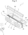
Figure 3 shows a schematic perspective view of the unit for inspecting multisegment articles ofFigure 2 ; -
Figure 4 shows a schematic side view of the unit for inspecting multisegment articles ofFigure 3 ; -
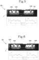
Figure 5 shows a two-dimensional image and a respective intensity graph generated by a prior art inspection unit and/or by applying a prior art inspection method; -
Figures 6 to 8 show two-dimensional images and respective intensity graphs generated by the units ofFigures 2-4 and/or by applying the method according to this invention, in different embodiments. - In the accompanying drawings, the
numeral 100 denotes in its entirety a rod-shaped multisegment article, and thenumeral 1 denotes in its entirety a unit for inspecting articles 100 (and represented schematically and only partially in the accompanying drawings) according to this invention. - The term "rod-shaped multisegment article" is used to mean a rod-shaped article divided into several segments and defining, or intended to define, a smoking article, in particular intended to form a smoking article suitable for generating an aerosol by heating, preferably by heat generated externally by electromagnetic induction or by conduction.
- The
article 100, as shown inFigure 1 , extends along a respective axis of extension X betweenopposite end surfaces lateral surface 100c extending between theend surfaces article 100 is divided at least into onefilter segment 101, oneclosing segment 102 and, between thefilter segment 101 and theclosing segment 102, other segments responsible for forming and treating the aerosol. These other segments may comprise, preferably, asegment 103 of material suitable for generating an aerosol by heating, and at least one tubular segment 104. Thus, thefilter segment 101, theclosing segment 102, thesegment 103 and the tubular segment 104 are disposed in sequence along the axis of extension X. - In detail, the
filter segment 101 and theclosing segment 102 are intended to define respectively afirst end surface 100a of thearticle 100 and asecond end surface 100b of thearticle 100. - The
segment 103 is adjacent to theclosing segment 102, while the at least one tubular segment 104 is placed between thesegment 103 and thefilter segment 101. - The
segment 103 may contain a generic material suitable for releasing an aerosol when heated, for example strips of tobacco or containing a tobacco flavouring, or a crimped sheet of tobacco or containing a tobacco flavouring. The at least one tubular segment 104 may act as a spacing element between thefilter element 101 and thesegment 103, and/or as a cooling element, suitable for lowering the temperature of the aerosol as a result of the user inhaling or of thesegment 103 itself being heated. - Alternatively, the tubular segment 104 is a spacer and is followed by a cooling segment with a non-tubular structure.
- In the embodiment illustrated in
Figure 1 , the tubular segment 104 is divided into a pair ofpieces - The
filter segment 101 and theclosing segment 102 of thesame article 100 have different axial lengths, that is to say, they differ in extent along the axis of extension X of thearticle 100. - Also, the
filter segment 101 and theclosing segment 102 are made of different materials, in particular selected between acetate, monoacetate and crimped paper. - For example, in one
article 100, thefilter segment 101 and theclosing segment 102 may be made of acetate and crimped paper, respectively, or of monoacetate and acetate, respectively. - Although made of different materials, the
filter segment 101 and theclosing segment 102 have the same outward appearance, in particular, they have the same colour, the same hue and the same surface structure. In particular, they have an uninterrupted end surface, preferably smooth, and are white in colour. Thus, it is not possible to visually distinguish between thefilter segment 101 and theclosing segment 102, that is to say, between thefirst end surface 100a and thesecond end surface 100b based on aesthetic parameters. - As will become clearer as this description continues, the invention involves arranging a plurality of
articles 100 in mutually juxtaposed fashion with the respective axes of extension X parallel to each other, preferably predetermined in number and distribution suitable for defining the contents of a standard packet, or alternatively, in a mass flow configuration (moving on a belt, downwards in a hopper) or, in yet another alternative, in a mass stored in trays or containers. - Next, the
lateral surface 100c of at least onearticle 100 is irradiated with a light beam F, which is conveyed around the plurality ofarticles 100 by alight guide 500 and, thanks to the fact that theclosing segment 102 and thefilter segment 101 have different axial lengths, detecting the light emitted frontally by the articles themselves allows obtaining information relating to the orientation of theirradiated article 100. - In particular, the absorption of the light beam F along the article 100 (that is, from the
lateral surface 100c to each of theend surfaces end segment article 100. - By "orientation" is meant the spatial position of the
article 100 along its axis of extension X. In particular, thearticle 100 has two possible orientations in two opposite directions. - Described in detail below are the procedures and means used for inspecting the
articles 100 according to the invention. - Preferably, the
unit 1 is positioned along a feed direction of thearticles 100 and is stationary. Alternatively, thearticles 100 may be at least temporarily stationary while theunit 1 is moved. Alternatively, both thearticles 100 and theunit 1 are moved. - Preferably, the
articles 100 are subjected to indirect guiding (during at least one step in which they are conveyed after they have been made), where such indirect guiding may be at theunit 1 or upstream of it. There would be no downside to placing theunit 1 at a remote position downstream of the indirect guiding, since the event that generates a wrong orientation of one or more articles only generates a wrong position of thearticle 100, which is the same as when it reaches theunit 1. - The term "indirect guiding" is used to mean a flow of
articles 100, where only a small number of the articles is directly in contact with a guiding part, such as, for example, a conveyor belt or a movable wall. - For example, indirect guiding may be the result of gravity feed inside a hopper or constrained guiding of a main (bottom) layer of
articles 100, which, by moving the main layer causes the peripheral (upper) layers ofarticles 100 on top of the main layer to move. This occurs, for example, in a mass flow (mass stream) when articles are being transported in a container or tray. - Thus, indirect guiding is indicated as an operative condition such as, potentially, to cause misalignment of one or
more articles 100 leading to them being incorrectly oriented. - With reference to
Figures 2 ,3 and4 , theunit 1 comprises at least one supportingelement 2, suitable for receiving a plurality ofarticles 100, for example from a hopper (not illustrated in the accompanying drawings), and for supporting the plurality ofarticles 100, positioned with their respective axes parallel to each other. - Preferably, the supporting
element 2 is movable and has a connecting portion 2', suitable for connecting the supportingelement 2 to a movement means such as a chain, a belt or other closed-loop conveyor. - Preferably, the supporting
element 2 is configured to support a plurality ofarticles 100 arranged along a plurality of superposed rows (two rows in the embodiment illustrated) so that thearticles 100 of different rows have their respective axes of extension X parallel to each other. - More preferably, the supporting
element 2 is configured to support a plurality ofarticles 100, defined by a group ofarticles 100 predetermined in number and distribution suitable for defining the contents of a standard packet to be made, and theunit 1 is preferably located upstream of a packing station. Thesupport 2 may therefore be a cleat of a cleated conveyor which feeds the articles from a hopper to a packing machine. - In detail, the supporting
element 2 has at least one containment compartment V for a plurality ofarticles 100. - In an embodiment illustrated in
Figures 2 ,3 and4 , the supportingelement 2 has two containment compartments V which are juxtaposed and separated from each other by amiddle wall 20. Each containment compartment V is intended to contain a respective plurality ofarticles 100. In detail, the supportingelement 2 is suitable for supporting thearticles 100 in such a way as to expose one of theend surfaces article 100. - To obtain information relating to an orientation of the
articles 100, the invention comprises first of all irradiating at least onearticle 100 with a light beam F, as shown inFigures 3 and4 . - The light beam F is preferably a laser beam.
- The light beam F is incident upon the
lateral surface 100c of at least onearticle 100. - In detail, irradiating the
lateral surface 100c makes it possible, using a specific device, to detect a light intensity diffused by anend surface article 100 and, thanks to that intensity, to derive information relating to an orientation of thearticle 100. In effect, thefilter segment 101, defining thefirst end 100a, and theclosing segment 102, defining thesecond end 100b, because they differ in axial length, cause the light beam F to be absorbed differently along each article 100 (that is to say, along the axis X), corresponding to different light intensities diffused by eachend surface - In detail, the light beam F is emitted along a direction or plane of emission E (schematically illustrated in
Figure 4 ) incident upon thelateral surface 100c of at least onearticle 100 and having a predetermined angle, preferably perpendicular, to a positioning plane of the irradiatedlateral surface 100. - In order to irradiate at least one
article 100, theunit 1 comprises at least one emittingdevice 3 positioned to face the supportingelement 2 and configured to emit the light beam F along the emitting direction E. - In an embodiment of the
unit 1, the emittingdevice 3 comprises a laser emitter, configured to emit a laser light. - A
similar emitter 3, configured to emit the laser beam F, may be positioned on the opposite side of the supportingelement 2. - Once the
lateral surface 100c of thearticle 100 has been irradiated by the light beam F, the luminous radiation emitted by theend surface article 100 of the plurality ofarticles 100. - The different axial extents of the
filter segment 101 and of theclosing segment 102 allows obtaining an identification signal associated with thefirst end surface 100a (defined by the filter segment 101) different from the identification signal associated with thesecond end surface 100b (defined by the closing segment 102). - Alternatively, the
emitter 3 is configured to emit a light beam F at a predefined distance from thesecond end surface 100b (defined by the closing segment 102) and such that, if thearticle 100 is well oriented (that is to say, is not incorrectly oriented), the light beam F is directed towards thesegment 103, which may contain a generic material suitable for forming an aerosol when heated, for example, strips of tobacco or containing a tobacco flavouring, or a crimped sheet of tobacco or containing a tobacco flavouring. Thesegment 103, unlike theother segments article 100, is capable of absorbing substantially all of the light beam F, thus interrupting its flow along thearticle 100; as a result, if thearticle 100 is incorrectly oriented, the light beam F is directed towards thefilter segment 101 and/or towards the tubular segment 104 which do allow the light beam F to be diffused along thearticle 100. The different capacities of thesegment 103, of thefilter segment 101 and of the tubular segment 104 to absorb the light beam F thus allows obtaining an identification signal associated with thefirst end surface 100a (defined by the filter segment 101) different from the identification signal associated with thesecond end surface 100b (defined by the closing segment 102). - Processing the identification signal thus makes it possible to distinguish the
end surfaces article 100. - Preferably, the step of generating the identification signal is carried out by optical inspection, performed along a detecting direction R incident upon the
end surface - More preferably, the detecting direction R is perpendicular to the positioning plane of the
end surface - To capture the identification signal, the
unit 1 comprises at least one detectingdevice 4, configured to capture along the detecting direction R the light diffused by theend surface device 4 is positioned to face the supportingelement 2. - The detecting
device 4 is also configured to generate a signal identifying the intensity of the captured light. - The identification signal comprises, for example, one or more digital images of the
end surfaces - The
unit 1 also comprises acontrol unit 5, configured to receive and process the signal generated by the detectingdevice 4. - In particular, the
control unit 5 is connected or connectable to the detectingdevice 4, for example, by specific wiring, by a wireless connection or other types of connections. In detail, thecontrol unit 5 is configured to receive the identification signal (for example, the aforesaid digital images) and to process the identification signal to obtain information relating to the orientation of eacharticle 100, in particular relating to the position of theend surfaces - As will become clearer as this description continues, the Applicant has found that using a
light guide 500 makes the information about the orientation of thearticles 100 more reliable, in particular when arranged in superposed rows, where a first row ofarticles 100 facing the emittingdevice 3 would otherwise mask the light beam F with respect to a second row ofarticles 100 juxtaposed with the first row and distal to the emittingdevice 3. In effect, according to an advantageous aspect of this invention, theunit 1 comprises at least onelight guide 500, at least partly surrounding the containment compartment V of the supportingelement 2. The invention comprises a step of inserting the plurality ofarticles 100 into the cavity "A" of thelight guide 500 so that thelight guide 500 at least partly surrounds the plurality ofarticles 100. - The
light guide 500 is configured to receive the light produced by the light beam F and to convey some of the light around the plurality ofarticles 100 positioned in the containment compartment V from a first zone of the plurality ofarticles 100 confronting the emittingdevice 3 towards a second zone of the plurality ofarticles 100 opposite the first zone. - In other words, the
light guide 500 is suitable for receiving the light beam F and conveying some of the light produced by it around the containment compartment V so as to irradiate the plurality ofarticles 100 contained therein. - The Applicant has noticed that using the
light guide 500 advantageously allows collecting the light produced by the light beam F, propagating along the emitting direction E and not directed towards thearticles 100 of the upper row, along an at least partly closed path surrounding thearticles 100, in particular around the respective axes of extension X, allowing the lateral surfaces 100c not directly exposed to the light beam F to be irradiated. The expression "lateral surfaces 100c not directly exposed to the light beam F" denotes the lateral surfaces 100c ofarticles 100 disposed in such a way thatother articles 100, in particular, those of the row underneath, mask the light beam F from them. In other words, although eacharticle 100 not directly exposed to the light beam F cannot be irradiated directly, nevertheless, thanks to thelight guide 500, the light produced by the light beam F can be diverted so that thosearticles 100 can also be irradiated. Thelight guide 500 thus allows obtaining an identification signal associated with thefilter segment 101 and an identification signal associated with theclosing segment 102 which are more easily distinguishable from each other. In more detail, the emitting direction E is incident upon thelight guide 500. Preferably, the emitting direction E is at an angle such as to allow aninside surface 501 of thelight guide 500, facing towards thearticles 100, to totally reflect a part of the light beam F so as to convey the maximum amount of remaining light (residual at the fraction that reaches the upper row of articles) around the containment compartment V, hence around thearticles 100. - Structurally, the
light guide 500 comprises afirst base wall 500a, asecond base wall 500b and at least oneside wall 500c positioned to join thebase walls - Preferably, the supporting
element 2 is configured to receive articles from a hopper (not shown in the accompanying drawings) and thefirst base wall 500a is a top wall, facing towards the hopper, while thesecond base wall 500b is a bottom wall, opposite thetop wall 500a. In the context of the invention, however, the terms "top" and "bottom" should be understood as being non-limiting in that embodiments where the emittingdevice 3 positioned under or laterally of the supportingelement 2 remain within the scope of the invention. - The
light guide 500 has at least one cavity A which is at least partly delimited by thebase walls side wall 500c. - The cavity A is open at the front and back, that is to say, it is a through cavity, and is suitable for at least partly defining the containment compartment V of the supporting
element 2 and for receiving the plurality ofarticles 100. - Therefore, the
light guide 500 is integrated preferably removably in the supportingelement 2. - According to an aspect of this invention, the
light guide 500 is made in the form of a contoured slab-like element, and the supportingelement 2 is preferably defined by a cleat of a cleated conveyor and comprises aslot 2a in which thelight guide device 500 is inserted or insertable, preferably removably, in particular along a direction perpendicular to the axis of extension X. - Therefore, the
light guide 500 is removable from the supportingelement 2, allowing it to be replaced when worn or for retrofitting on existing supporting elements 2 (which may be machined to make theaforementioned slot 2a, for example by milling). - In use, the
light guide 500 is positioned to confront the emittingdevice 3 to receive the light beam F at thefirst base wall 500a and is configured to convey the received light from thefirst base wall 500a to thesecond base wall 500b and around the cavity A; that way, the light conveyed around the plurality ofarticles 100 is directed from a first zone (proximal to thefirst base wall 500a) to a second zone (proximal to thesecond base wall 500b) of the plurality ofarticles 100. - More in detail, the
first base wall 500a, in use, is at least partly traversed by the light beam F) so that a first part of the light beam F reaches the first zone of the plurality ofarticles 100 and a second part of the light beam F remains trapped in thelight guide 500 and is guided by it towards the second zone of the plurality ofarticles 100. - In other words, a first row of
articles 100 which confronts the emittingdevice 3 is, in use, irradiated by the first part of the light beam F through thefirst base wall 500a, while a second row ofarticles 100 which, in use, is positioned in such a way as to be masked by the first row, is irradiated by the second part of the light beam F, guided by thelight guide 500. Preferably, thefirst wall 500a has a break zone, extending for the whole length of thelight guide 500 along the axis of extension X and preferably located in a central zone of thefirst base wall 500a. - Preferably, the
light guide 500 is made as a single block. - Preferably, the
light guide 500 is made of a transparent material, preferably glass, polycarbonate or Plexiglas. - Preferably, the
light guide 500 is made in the form of an insert, made of material transparent to the light beam, insertable in the containment compartment and being, in particular, extractable. - According to an aspect of this invention, at least one inside
wall 501 of thelight guide 500, preferably eachinside wall 501, facing towards the containment compartment V is aligned flush with the corresponding inside wall of the supportingelement 2 facing towards the containment compartment V. - In other words, the containment compartment V of the supporting
element 2 and the cavity A of thelight guide 500 are substantially identical and superposable. - According to an aspect of this invention, the
light guide 500, in a cross section transverse to the axis of extension X is substantially identical to the supportingelement 2. - In the embodiment in which the supporting
element 2 has two containment compartments V, thelight guide 500 comprises a plurality of cavities A, each corresponding to, and associated or associable with, a respective containment compartment V. - Alternatively, the
unit 1 comprises a respective plurality of light guides (500), each light guide (500) being associated with a respective containment compartment V to surround the respective plurality ofarticles 100. - In another embodiment, the
light guide 500 defines a cleat of a cleated conveyor, hence the supportingelement 2. - According to an advantageous aspect of this invention, the
unit 1 comprises areflective element 600 associated with thelight guide 500 at least in the second zone of the plurality ofarticles 100, preferably at thesecond base wall 500b. - The
reflective element 600 is located at a position opposite the containment compartment V so that the light conveyed by thelight guide 500 is reflected towards thearticles 100. - Thus, the
reflective element 600 allows the plurality ofarticles 100 to be irradiated better so that the information regarding an orientation of thearticles 100 is more reliable. - Preferably, the
reflective element 600 is positioned directly in contact with thelight guide 500. - In order to maximize the advantages offered by the
reflective element 600, in an embodiment, thereflective element 600 is positioned at thesecond base wall 500b and at theside wall 500c of thelight guide 500. - The
reflective element 600 comprises a strip, preferably flexible, made of a material selected between foil and paper, preferably white paper. According to an aspect of this invention, the detectingdevice 4 comprises a camera which faces theend surface dimensional image 300, illustrated inFigures 6 ,7 and 8 , containing theend surface image 300 to thecontrol unit 5. Thus, the signal identifying the intensity of the light emitted by anend surface image 300 and thecontrol unit 5 is configured to receive theimage 300 and to process it, preferably by comparing theimage 300 with a reference image and/or by running a digital image analysis algorithm. - More preferably, the
control unit 5 is configured to process theimage 300 by identifying at least one region of theimage 300 corresponding to the detectedend surface - For example, and with reference to
Figures 6 to 8 , thecontrol unit 5 is configured to process theimage 300 to obtain the intensity values, in particular the values of the shades of grey, of theimage 300 itself along a detection line Y passing through a row ofarticles 100. -
Figure 5 shows a two-dimensional image 300 captured by thedetection device 4 when the detection device comprises a camera in the case where theunit 1 is without the light guide 500 (traditional solution), and a graph representing the intensity of theimage 300 captured along the detection line Y. In detail, along the detection line Y, the articles labelled with the numeral 1000 are incorrectly oriented. - The graph of
Figure 5 shows the values of grey associated withdifferent articles article 100. Thus, it is difficult to identify a value of grey extraneous to an occurrence of values of grey along the detection line Y, identifying incorrectly orientedarticles 1000. -
Figure 6 shows the same two-dimensional image 300 asFigure 5 , detected in the case where theunit 1 comprises thelight guide 500, and a graph representing the intensity of theimage 300 captured along a detection line Y. - The values of grey of
Figure 6 are more uniform for eacharticle article -
Figure 7 shows a two-dimensional image 300 captured by thedetection device 4 when the detection device comprises a camera in the case where theunit 1 comprises both thelight guide 500 and thereflective element 600 made of white paper, and a graph representing the intensity of theimage 300 captured along the detection line Y. -
Figure 8 shows a two-dimensional image 300 captured by thedetection device 4 when the detection device comprises a camera in the case where theunit 1 comprises both thelight guide 500 and thereflective element 600 made of foil paper, and a graph representing the intensity of theimage 300 captured along the detection line Y. - In both the graphs of
Figures 7 and 8 , the values of grey are uniform for eacharticle article - In addition, both the graphs of
Figures 7 and 8 allow identifying the incorrectly orientedarticles 1000, since the grey values associated with them are clearly different from the grey values of theother articles 100, which are correctly oriented. - Thus, the
light guide 500 and thereflective element 600 act in conjunction to obtain more reliable information regarding the orientation of thearticles 100. - The invention achieves the above-mentioned aims by eliminating the drawbacks of the prior art: in this regard, it should be noted that the method for inspecting
articles 100, as well as theunit 1, as claimed and/or described herein, are capable of identifying the orientation ofindividual articles 100 of a plurality ofarticles 100 in a compact manner and with improved reliability. This result was achieved thanks to thelight guide 500 and, preferably, also thereflective element 600 which allow diverting the light produced by the light beam F in such a way as to improve theway articles 100 arranged in superposed rows are irradiated.
Claims (23)
- A unit (1) for inspecting multisegment, rod-shaped articles (100), in particular defining or intended to define smoking articles suitable for generating aerosols by heating,
wherein each article (100) extends along a respective axis of extension (X) between opposite end surfaces (100a, 100b), made from respective different materials, and is delimited by a lateral surface (100c) extending around the axis of extension (X) and between the end surfaces (100a, 100b) and wherein the unit (1) comprises:- at least one supporting element (2) having at least one containment compartment (V) for a plurality of articles (100) positioned with their respective axes (X) parallel to each other;- at least one emitting device (3), positioned to confront the supporting element (2) and configured to emit a light beam (F) in the direction of the lateral surface (100c) of at least one article (100) of the plurality of articles (100);- at least one detecting device (4), positioned to confront the supporting element (2) and configured to capture the light emitted by an end surface (100a, 100b) of the article (100) and produced by the light beam (F) and to generate an identification signal identifying the intensity of the light captured;- a control unit (5) connected or connectable to the detecting device (4) and configured to receive the identification signal and to process the identification signal to obtain an information item relating to the orientation of each article (100) of the plurality of articles (100), in particular relating to the position of the end surfaces (100a, 100b) of the article (100),- at least one light guide (500), at least partly surrounding the containment compartment (V) and configured to receive the light produced by the light beam (F) and to convey the light around the plurality of articles (100) positioned in the containment compartment (V) from a first zone of the plurality of articles (100) confronting the emitting device (3) towards a second zone of the plurality of articles (100) opposite the first zone. - The unit (1) according to claim 1, wherein the light guide (500) comprises a first base wall (500a), a second base wall (500b) and at least one side wall (500c) positioned to join the base walls (500a, 500b); the light guide (500) having at least one cavity (A) at least partly delimited by the base walls (500a, 500b) and side wall (500c), the cavity (A) being open at the front and back and suitable for at least partly defining the containment compartment (V) and for receiving the plurality of articles (100).
- The unit (1) according to claim 2, wherein the light guide (500) is positioned to confront the emitting device (3) to receive the light beam (F) at the first base wall (500a) and is configured to convey the received light from the first base wall (500a) to the second base wall (500b) and around the cavity (A) so as to direct the light, conveyed around the plurality of articles (100), from the first to the second zone of the plurality of articles (100).
- The unit (1) according to claim 2 or 3, wherein the first base wall (500a), in use, is at least partly traversed by the light beam (F) so that a first part of the light beam (F) reaches the first zone of the plurality of articles (100) and a second part of the light beam (F) remains trapped in the light guide (500) and is guided by it towards the second zone of the plurality of articles (100).
- The unit (1) according to any one of claims 2 to 4, wherein the first wall has a break zone, extending for the whole length of the light guide (500) along the axis of extension (X) and preferably located in a central zone of the first wall.
- The unit (1) according to any one of the preceding claims, wherein the light guide (500) is made as a single block.
- The unit (1) according to any one of the preceding claims, wherein the light guide (500) is made from a transparent material, preferably glass, polycarbonate or Plexiglas.
- The unit (1) according to claim 7, wherein said light guide (500) is made in the form of an insert which is insertable into the containment compartment (V), preferably removably.
- The unit (1) according to any one of the preceding claims, wherein the light guide (500) is, in cross section transverse to the axis of extension (X), substantially identical in shape to the supporting element (2).
- The unit (1) according to any one of the preceding claims, wherein at least one inside wall of the light guide (500), preferably each inside wall, facing towards the containment compartment (V) is aligned flush with the corresponding inside wall of the supporting element (2) facing towards the containment compartment (V).
- The unit (1) according to any one of the preceding claims, wherein the light guide (500) is made in the form of a contoured slab-like element, and wherein the supporting element (2) is defined by a cleat of a cleated conveyor, the supporting element (2) comprising a slot (2a) in which the light guide device (500) is inserted or insertable, preferably removably, in particular along a direction perpendicular to the axis of extension (X).
- The unit (1) according to any one of the preceding claims, comprising a reflective element (600) associated with the light guide (500) at least in the second zone of the plurality of articles (100) and located at a position opposite the containment compartment (V) so that the light conveyed by the light guide (500) is reflected towards the articles (100), the reflective element (600) being preferably positioned directly in contact with the light guide (500).
- The unit according to claim 12 when dependent on claim 2, wherein the reflective element (600) is associated at least with the second base wall (500b) of the light guide (500).
- The unit (1) according to claim 12 when dependent on claim 2 or claim 13, wherein the reflective element (600) is positioned at least at the side wall of the light guide (500).
- The unit (1) according to any one of claims 12 to 14, wherein the reflective element (600) comprises a strip, preferably flexible, made from a material selected between foil and paper, preferably white paper.
- The unit (1) according to any one of the preceding claims, wherein the supporting element (2) has two containment compartments (V), juxtaposed with each other and separated by a central wall (20), each containment compartment (V) being intended to contain a respective plurality of articles (100) arranged in superposed rows and with the respective axes (X) parallel with each other and preferably predetermined in number and suitable, in number and distribution, for defining the content of a standard packet to be made,
and wherein the light guide (500) comprises a plurality of cavities (A), each corresponding to a respective containment compartment (V). - The unit (1) according to any one of claims 1 to 15, wherein the supporting element (2) has two containment compartments (V), juxtaposed with each other and separated by a central wall (20), each containment compartment (V) being intended to contain a respective plurality of articles (100) arranged in superposed rows and with the respective axes (X) which are parallel with each other, preferably predetermined in number and suitable, in number and distribution, for defining the content of a standard packet to be made,
and wherein the unit (1) comprises a respective plurality of light guides (500), each light guide (500) being associated with a respective containment compartment (V) to surround the respective plurality of articles (100). - The unit (1) according to claim 1, wherein the supporting element (2) is defined by the light guide device (500).
- The unit (1) according to any one of the preceding claims, wherein the emitting device (3) has an emitting direction (E) that is incident upon the light guide (500) and at an angle such as to allow an inside surface (501) of the light guide (500), facing towards the articles (100), to totally reflect a part of the light beam (F).
- The unit (1) according to according to any one of the preceding claims, wherein detecting device (4) comprises a camera (4) which faces the end surface (100a, 100b) to be inspected and which is configured to capture a two-dimensional image (300) containing the end surface (100a, 100b) and to transmit the image (300) to the control unit (5), in particular to compare the image (300) with a reference image and/or to run a digital image analysis algorithm, preferably identifying at least one region of the image (300) corresponding to the detected end surface (100a, 100b) of the at least one article (100) and considering the filling intensity of the at least one region.
- A method for inspecting multisegment, rod-shaped articles (100), in particular defining or intended to define smoking articles suitable for generating aerosols by heating,wherein each article (100) extends along a respective axis of extension (X) between opposite end surfaces (100a, 100b), made from respective different materials, and is delimited by a lateral surface (100c) extending around the axis of extension (X) and between the end surfaces (100a, 100b) wherein the method is preferably implemented by an inspection unit (1) according to one or more of the preceding claims,the method comprising the following steps:- providing a plurality of articles (100) arranged along at least one row and positioned in a mutually juxtaposed configuration with their respective axes of extension (X) parallel to each other;- providing a light guide (500) comprising a cavity (A);- inserting the plurality of articles (100) into the cavity (A) of the light guide (500) so that the light guide (500) at least partly surrounds the plurality of articles (100);- radiating the plurality of articles (100) with the at least one light beam (F) incident upon a first zone of the plurality of articles (100) so that a first part of the light beam (F) reaches the first zone of the plurality of articles (100) and conveying a second part of the light beam (F) through the light guide (500) around the plurality of articles (100) from the first zone of the plurality of articles (100) towards a second zone of the plurality of articles (100) opposite the first zone;- generating at least one identification signal identifying the intensity of the light diffused by the end surface (100a, 100b) of the radiated article (100) and produced by the light beam (F);- processing the signal to obtain an information item relating to the orientation of each article (100) of the plurality of articles (100), in particular relating to the spatial arrangement of the first and the second end surface (100a, 100b) of the article (100).
- The method according to claim 21, wherein the step of radiating the plurality of articles with the at least one light beam (F) is carried out by radiating a portion of the light guide (500) positioned at the first zone of the plurality of articles (100) so that the first part of the light beam (F) passes through the light guide (500) and the second part of the light beam (F) remains trapped in the light guide (500) and is guided by it towards the second zone of the plurality of articles (100).
- The method according to claim 21 or 22, wherein the end surfaces (100a, 100b) of the article (100) are defined by respective segments (101, 102) made of different materials, selected from the following: acetate, monoacetate or crimped paper.
Applications Claiming Priority (1)
| Application Number | Priority Date | Filing Date | Title |
|---|---|---|---|
| IT102023000018198A IT202300018198A1 (en) | 2023-09-05 | 2023-09-05 | METHOD AND UNIT FOR INSPECTION OF MULTI-SEGMENT BAR-SHAPED ARTICLES |
Publications (2)
| Publication Number | Publication Date |
|---|---|
| EP4529778A1 true EP4529778A1 (en) | 2025-04-02 |
| EP4529778B1 EP4529778B1 (en) | 2025-10-15 |
Family
ID=88778996
Family Applications (1)
| Application Number | Title | Priority Date | Filing Date |
|---|---|---|---|
| EP24197703.2A Active EP4529778B1 (en) | 2023-09-05 | 2024-08-30 | Method and unit for inspecting multisegment rod-shaped articles |
Country Status (2)
| Country | Link |
|---|---|
| EP (1) | EP4529778B1 (en) |
| IT (1) | IT202300018198A1 (en) |
Citations (5)
| Publication number | Priority date | Publication date | Assignee | Title |
|---|---|---|---|---|
| US4511045A (en) * | 1981-03-06 | 1985-04-16 | G.D. Societa Per Azioni | Device for transferring and verifying batches of cigarettes |
| US5127737A (en) * | 1989-01-13 | 1992-07-07 | G. D. Societa Per Azioni | Cigarette end group inspection system |
| DE19753333A1 (en) * | 1997-12-02 | 1999-06-10 | Focke & Co | Procedure for checking the completeness of cigarette groups and the filling of the cigarettes |
| WO2007086744A1 (en) * | 2006-01-26 | 2007-08-02 | Bravilor Holding B.V. | Optical filling level detection device for powder material |
| WO2021165303A1 (en) | 2020-02-21 | 2021-08-26 | Focke & Co. (Gmbh & Co. Kg) | Method and device for examining rod-shaped products of the cigarette industry |
-
2023
- 2023-09-05 IT IT102023000018198A patent/IT202300018198A1/en unknown
-
2024
- 2024-08-30 EP EP24197703.2A patent/EP4529778B1/en active Active
Patent Citations (6)
| Publication number | Priority date | Publication date | Assignee | Title |
|---|---|---|---|---|
| US4511045A (en) * | 1981-03-06 | 1985-04-16 | G.D. Societa Per Azioni | Device for transferring and verifying batches of cigarettes |
| US5127737A (en) * | 1989-01-13 | 1992-07-07 | G. D. Societa Per Azioni | Cigarette end group inspection system |
| DE19753333A1 (en) * | 1997-12-02 | 1999-06-10 | Focke & Co | Procedure for checking the completeness of cigarette groups and the filling of the cigarettes |
| WO2007086744A1 (en) * | 2006-01-26 | 2007-08-02 | Bravilor Holding B.V. | Optical filling level detection device for powder material |
| WO2021165303A1 (en) | 2020-02-21 | 2021-08-26 | Focke & Co. (Gmbh & Co. Kg) | Method and device for examining rod-shaped products of the cigarette industry |
| US20230073296A1 (en) * | 2020-02-21 | 2023-03-09 | Focke & Co. (Gmbh & Co. Kg) | Method and device for examining rod-shaped products of the cigarette industry |
Also Published As
| Publication number | Publication date |
|---|---|
| IT202300018198A1 (en) | 2025-03-05 |
| EP4529778B1 (en) | 2025-10-15 |
Similar Documents
| Publication | Publication Date | Title |
|---|---|---|
| AU774359B2 (en) | Inspection of matter | |
| JP5358073B2 (en) | Package inspection system and inspection method | |
| KR100853340B1 (en) | Apparatus and method for visually inspecting cigarette packaging processes | |
| US4486098A (en) | Method and apparatus for testing the ends of cigarettes or the like | |
| CN104919273B (en) | The assembly of the bands of muscle of the contactless identification device and method of red institutional framework and the red institutional framework of removal | |
| JP7325390B2 (en) | Article inspection device | |
| JPH068129B2 (en) | Equipment for inspecting cigarettes for defects in tobacco or filters | |
| JP2001225029A (en) | Transport equipment for online internal quality inspection | |
| IL189621A (en) | Egg counter for counting eggs transferred by egg collection conveyer | |
| EP1746409A1 (en) | On-line internal quality examining method and device | |
| JPH10202205A (en) | Receiving tray for sorting machine and agricultural product sorting device | |
| KR102362846B1 (en) | Inspection device, PTP packaging machine, and method of manufacturing PTP sheet | |
| EP4529778B1 (en) | Method and unit for inspecting multisegment rod-shaped articles | |
| US20020074511A1 (en) | Missing lens detection system and method | |
| EP3465178B1 (en) | Apparatus for identification of physical parameters of rod-like articles of the tobacco industry | |
| EP1698888A2 (en) | Inspection of matter | |
| JP4424537B2 (en) | Foreign matter inspection device | |
| JP7735289B2 (en) | Method and apparatus for inspecting rod products in the cigarette industry | |
| WO2018135232A1 (en) | Foreign matter detection device, foreign matter detection method and manufacturing device | |
| US7323881B2 (en) | Process and apparatus for evaluating the degree of vacuum in closed bodies with transparent walls | |
| EP4723907A1 (en) | Method and unit for inspection of multi-segment rod-shaped articles | |
| JP3500283B2 (en) | Transmitted light detector for agricultural products | |
| JP7325383B2 (en) | Article inspection device | |
| JPH10246702A (en) | Tablet and other identification devices and packaging systems | |
| JP2025090207A (en) | Transport System |
Legal Events
| Date | Code | Title | Description |
|---|---|---|---|
| PUAI | Public reference made under article 153(3) epc to a published international application that has entered the european phase |
Free format text: ORIGINAL CODE: 0009012 |
|
| STAA | Information on the status of an ep patent application or granted ep patent |
Free format text: STATUS: THE APPLICATION HAS BEEN PUBLISHED |
|
| AK | Designated contracting states |
Kind code of ref document: A1 Designated state(s): AL AT BE BG CH CY CZ DE DK EE ES FI FR GB GR HR HU IE IS IT LI LT LU LV MC ME MK MT NL NO PL PT RO RS SE SI SK SM TR |
|
| STAA | Information on the status of an ep patent application or granted ep patent |
Free format text: STATUS: REQUEST FOR EXAMINATION WAS MADE |
|
| GRAP | Despatch of communication of intention to grant a patent |
Free format text: ORIGINAL CODE: EPIDOSNIGR1 |
|
| STAA | Information on the status of an ep patent application or granted ep patent |
Free format text: STATUS: GRANT OF PATENT IS INTENDED |
|
| 17P | Request for examination filed |
Effective date: 20250409 |
|
| RIC1 | Information provided on ipc code assigned before grant |
Ipc: A24C 5/34 20060101AFI20250424BHEP |
|
| INTG | Intention to grant announced |
Effective date: 20250508 |
|
| GRAS | Grant fee paid |
Free format text: ORIGINAL CODE: EPIDOSNIGR3 |
|
| GRAA | (expected) grant |
Free format text: ORIGINAL CODE: 0009210 |
|
| STAA | Information on the status of an ep patent application or granted ep patent |
Free format text: STATUS: THE PATENT HAS BEEN GRANTED |
|
| P01 | Opt-out of the competence of the unified patent court (upc) registered |
Free format text: CASE NUMBER: UPC_APP_5786_4529778/2025 Effective date: 20250903 |
|
| AK | Designated contracting states |
Kind code of ref document: B1 Designated state(s): AL AT BE BG CH CY CZ DE DK EE ES FI FR GB GR HR HU IE IS IT LI LT LU LV MC ME MK MT NL NO PL PT RO RS SE SI SK SM TR |
|
| REG | Reference to a national code |
Ref country code: GB Ref legal event code: FG4D Ref country code: CH Ref legal event code: F10 Free format text: ST27 STATUS EVENT CODE: U-0-0-F10-F00 (AS PROVIDED BY THE NATIONAL OFFICE) Effective date: 20251015 |
|
| REG | Reference to a national code |
Ref country code: DE Ref legal event code: R096 Ref document number: 602024000951 Country of ref document: DE |
|
| REG | Reference to a national code |
Ref country code: IE Ref legal event code: FG4D |
|
| REG | Reference to a national code |
Ref country code: NL Ref legal event code: MP Effective date: 20251015 |
|
| REG | Reference to a national code |
Ref country code: AT Ref legal event code: MK05 Ref document number: 1846111 Country of ref document: AT Kind code of ref document: T Effective date: 20251015 |
|
| PG25 | Lapsed in a contracting state [announced via postgrant information from national office to epo] |
Ref country code: NL Free format text: LAPSE BECAUSE OF FAILURE TO SUBMIT A TRANSLATION OF THE DESCRIPTION OR TO PAY THE FEE WITHIN THE PRESCRIBED TIME-LIMIT Effective date: 20251015 |
|
| PG25 | Lapsed in a contracting state [announced via postgrant information from national office to epo] |
Ref country code: ES Free format text: LAPSE BECAUSE OF FAILURE TO SUBMIT A TRANSLATION OF THE DESCRIPTION OR TO PAY THE FEE WITHIN THE PRESCRIBED TIME-LIMIT Effective date: 20251015 |
|
| REG | Reference to a national code |
Ref country code: LT Ref legal event code: MG9D |
|
| PG25 | Lapsed in a contracting state [announced via postgrant information from national office to epo] |
Ref country code: NO Free format text: LAPSE BECAUSE OF FAILURE TO SUBMIT A TRANSLATION OF THE DESCRIPTION OR TO PAY THE FEE WITHIN THE PRESCRIBED TIME-LIMIT Effective date: 20260115 |
|
| PG25 | Lapsed in a contracting state [announced via postgrant information from national office to epo] |
Ref country code: HR Free format text: LAPSE BECAUSE OF FAILURE TO SUBMIT A TRANSLATION OF THE DESCRIPTION OR TO PAY THE FEE WITHIN THE PRESCRIBED TIME-LIMIT Effective date: 20251015 Ref country code: FI Free format text: LAPSE BECAUSE OF FAILURE TO SUBMIT A TRANSLATION OF THE DESCRIPTION OR TO PAY THE FEE WITHIN THE PRESCRIBED TIME-LIMIT Effective date: 20251015 Ref country code: AT Free format text: LAPSE BECAUSE OF FAILURE TO SUBMIT A TRANSLATION OF THE DESCRIPTION OR TO PAY THE FEE WITHIN THE PRESCRIBED TIME-LIMIT Effective date: 20251015 |
|
| PG25 | Lapsed in a contracting state [announced via postgrant information from national office to epo] |
Ref country code: RS Free format text: LAPSE BECAUSE OF FAILURE TO SUBMIT A TRANSLATION OF THE DESCRIPTION OR TO PAY THE FEE WITHIN THE PRESCRIBED TIME-LIMIT Effective date: 20260115 |
|
| PG25 | Lapsed in a contracting state [announced via postgrant information from national office to epo] |
Ref country code: IS Free format text: LAPSE BECAUSE OF FAILURE TO SUBMIT A TRANSLATION OF THE DESCRIPTION OR TO PAY THE FEE WITHIN THE PRESCRIBED TIME-LIMIT Effective date: 20260215 |
|
| PG25 | Lapsed in a contracting state [announced via postgrant information from national office to epo] |
Ref country code: PT Free format text: LAPSE BECAUSE OF FAILURE TO SUBMIT A TRANSLATION OF THE DESCRIPTION OR TO PAY THE FEE WITHIN THE PRESCRIBED TIME-LIMIT Effective date: 20260216 |
|
| PG25 | Lapsed in a contracting state [announced via postgrant information from national office to epo] |
Ref country code: PL Free format text: LAPSE BECAUSE OF FAILURE TO SUBMIT A TRANSLATION OF THE DESCRIPTION OR TO PAY THE FEE WITHIN THE PRESCRIBED TIME-LIMIT Effective date: 20251015 |
|
| PG25 | Lapsed in a contracting state [announced via postgrant information from national office to epo] |
Ref country code: LV Free format text: LAPSE BECAUSE OF FAILURE TO SUBMIT A TRANSLATION OF THE DESCRIPTION OR TO PAY THE FEE WITHIN THE PRESCRIBED TIME-LIMIT Effective date: 20251015 |
|
| PG25 | Lapsed in a contracting state [announced via postgrant information from national office to epo] |
Ref country code: BG Free format text: LAPSE BECAUSE OF FAILURE TO SUBMIT A TRANSLATION OF THE DESCRIPTION OR TO PAY THE FEE WITHIN THE PRESCRIBED TIME-LIMIT Effective date: 20251015 |
|
| PG25 | Lapsed in a contracting state [announced via postgrant information from national office to epo] |
Ref country code: LT Free format text: LAPSE BECAUSE OF FAILURE TO SUBMIT A TRANSLATION OF THE DESCRIPTION OR TO PAY THE FEE WITHIN THE PRESCRIBED TIME-LIMIT Effective date: 20251015 |
|
| PG25 | Lapsed in a contracting state [announced via postgrant information from national office to epo] |
Ref country code: SM Free format text: LAPSE BECAUSE OF FAILURE TO SUBMIT A TRANSLATION OF THE DESCRIPTION OR TO PAY THE FEE WITHIN THE PRESCRIBED TIME-LIMIT Effective date: 20251015 |
|
| REG | Reference to a national code |
Ref country code: DE Ref legal event code: R026 Ref document number: 602024000951 Country of ref document: DE |
|
| PG25 | Lapsed in a contracting state [announced via postgrant information from national office to epo] |
Ref country code: DK Free format text: LAPSE BECAUSE OF FAILURE TO SUBMIT A TRANSLATION OF THE DESCRIPTION OR TO PAY THE FEE WITHIN THE PRESCRIBED TIME-LIMIT Effective date: 20251015 |
|
| PG25 | Lapsed in a contracting state [announced via postgrant information from national office to epo] |
Ref country code: IT Free format text: LAPSE BECAUSE OF FAILURE TO SUBMIT A TRANSLATION OF THE DESCRIPTION OR TO PAY THE FEE WITHIN THE PRESCRIBED TIME-LIMIT Effective date: 20251015 |
|
| PLBI | Opposition filed |
Free format text: ORIGINAL CODE: 0009260 |
|
| REG | Reference to a national code |
Ref country code: CH Ref legal event code: L10 Free format text: ST27 STATUS EVENT CODE: U-0-0-L10-L00 (AS PROVIDED BY THE NATIONAL OFFICE) Effective date: 20260715 |
|
| PG25 | Lapsed in a contracting state [announced via postgrant information from national office to epo] |
Ref country code: EE Free format text: LAPSE BECAUSE OF FAILURE TO SUBMIT A TRANSLATION OF THE DESCRIPTION OR TO PAY THE FEE WITHIN THE PRESCRIBED TIME-LIMIT Effective date: 20251015 |
|
| PG25 | Lapsed in a contracting state [announced via postgrant information from national office to epo] |
Ref country code: CZ Free format text: LAPSE BECAUSE OF FAILURE TO SUBMIT A TRANSLATION OF THE DESCRIPTION OR TO PAY THE FEE WITHIN THE PRESCRIBED TIME-LIMIT Effective date: 20251015 |
|
| PG25 | Lapsed in a contracting state [announced via postgrant information from national office to epo] |
Ref country code: SK Free format text: LAPSE BECAUSE OF FAILURE TO SUBMIT A TRANSLATION OF THE DESCRIPTION OR TO PAY THE FEE WITHIN THE PRESCRIBED TIME-LIMIT Effective date: 20251015 |
|
| PLAX | Notice of opposition and request to file observation + time limit sent |
Free format text: ORIGINAL CODE: EPIDOSNOBS2 |
|
| PG25 | Lapsed in a contracting state [announced via postgrant information from national office to epo] |
Ref country code: SE Free format text: LAPSE BECAUSE OF FAILURE TO SUBMIT A TRANSLATION OF THE DESCRIPTION OR TO PAY THE FEE WITHIN THE PRESCRIBED TIME-LIMIT Effective date: 20251015 |
|
| 26 | Opposition filed |
Opponent name: FOCKE & CO. (GMBH & CO. KG) Effective date: 20260706 |