EP4529361A1 - Monitoring of x-ray tubes - Google Patents
Monitoring of x-ray tubes Download PDFInfo
- Publication number
- EP4529361A1 EP4529361A1 EP23198465.9A EP23198465A EP4529361A1 EP 4529361 A1 EP4529361 A1 EP 4529361A1 EP 23198465 A EP23198465 A EP 23198465A EP 4529361 A1 EP4529361 A1 EP 4529361A1
- Authority
- EP
- European Patent Office
- Prior art keywords
- sensor
- tube
- monitoring system
- ray tube
- signal
- Prior art date
- Legal status (The legal status is an assumption and is not a legal conclusion. Google has not performed a legal analysis and makes no representation as to the accuracy of the status listed.)
- Withdrawn
Links
Images


Classifications
-
- H—ELECTRICITY
- H01—ELECTRIC ELEMENTS
- H01J—ELECTRIC DISCHARGE TUBES OR DISCHARGE LAMPS
- H01J35/00—X-ray tubes
- H01J35/02—Details
- H01J35/04—Electrodes ; Mutual position thereof; Constructional adaptations therefor
- H01J35/08—Anodes; Anti cathodes
- H01J35/10—Rotary anodes; Arrangements for rotating anodes; Cooling rotary anodes
-
- H—ELECTRICITY
- H05—ELECTRIC TECHNIQUES NOT OTHERWISE PROVIDED FOR
- H05G—X-RAY TECHNIQUE
- H05G1/00—X-ray apparatus involving X-ray tubes; Circuits therefor
- H05G1/02—Constructional details
-
- H—ELECTRICITY
- H05—ELECTRIC TECHNIQUES NOT OTHERWISE PROVIDED FOR
- H05G—X-RAY TECHNIQUE
- H05G1/00—X-ray apparatus involving X-ray tubes; Circuits therefor
- H05G1/08—Electrical details
- H05G1/26—Measuring, controlling or protecting
- H05G1/54—Protecting or lifetime prediction
-
- H—ELECTRICITY
- H05—ELECTRIC TECHNIQUES NOT OTHERWISE PROVIDED FOR
- H05G—X-RAY TECHNIQUE
- H05G1/00—X-ray apparatus involving X-ray tubes; Circuits therefor
- H05G1/08—Electrical details
- H05G1/66—Circuit arrangements for X-ray tubes with target movable relatively to the anode
Definitions
- the invention relates to systems and methods for monitoring X-ray tubes.
- Predictive maintenance in X-ray imaging aims to determine the condition of the tube and predict service intervals and remaining lifetime based on signals recorded by sensors. Obtaining reliable sensor signals in the adverse conditions prevailing in the tube remains a challenge.
- a first aspect of invention provides a monitoring system for an X-ray tube, the monitoring system being configured to receive a sensor signal from a tube sensor arrangement, wherein the tube sensor arrangement comprises a quantum sensor positioned in use to monitor an operational parameter of the X-ray tube, the monitoring system being further configured to process the sensor signal to generate an output signal for health monitoring or feedback control of the X-ray tube.
- the quantum sensor may comprise a nitrogen-vacancy (NV) diamond sensor, i.e., a quantum sensor which uses solid-state qubits embedded within the nitrogen-vacancy center of a diamond.
- NV nitrogen-vacancy
- Such sensors operate with a D.C. to GHz bandwidth using diamonds in the ⁇ m size range and have been shown to function from 4-625 Kelvin, in magnetic fields of up to 8.3 T, and pressures up to 13.6 GPa.
- the Rydberg state in such sensors may be prepared with a green laser.
- the tube sensor arrangement may comprise an optically pumped magnetometer (OPM), i.e., a quantum sensor which uses a highly excited atomic gas for field probing based on the quantized energy levels which are altered by external fields.
- OPM optically pumped magnetometer
- sensors comprise a small glass chamber (in the mm size range) filled with an alkali metal gas (e.g. Rubidium). Rydberg states in such sensors may be prepared and probed with two lasers (e.g. blue and near-infrared).
- the types of quantum sensors as described herein are non-limiting and that other types of quantum sensors may be developed in the future which would provide the same functionality.
- the monitoring system may comprise one or more traditional sensors (e.g., MEMS, electromagnetic sensors) alongside the quantum sensor.
- the tube sensor arrangement may comprise one or more laser sources for preparing the quantum sensor and/or for probing the quantum sensor to extract the signal to be monitored.
- laser light absorption changes with the local electromagnetic field, which interacts with the Rydberg state superposition prepared by a first laser (driving a Rabi oscillation) and probed by a second laser.
- the tube sensor arrangement may further comprise an optical fiber for conveying laser light to and/or from the quantum sensor.
- the quantum sensor can be read out with laser light.
- the optical signal may be digitized (via optical-to-digital conversion circuitry) before being processed by the monitoring system to generate the output signal.
- Real-time radiative field information (transmitted at light speed) at a high bandwidth is available from the quantum sensor, so the digitization is preferably performed late, i.e., by optical-to-electrical conversion circuitry which resides outside of the X-ray tube, for example in the X-ray generator.
- the optical-to-electrical conversion circuitry may be viewed as forming part of the tube sensor arrangement and/or part of the monitoring system, depending on the implementation.
- the tube sensor arrangement may comprise a set of quantum sensors distributed within or around the X-Ray tube or an X-ray generator that comprises the X-ray tube.
- the tube sensor arrangement comprises a quantum sensor within the X-ray tube itself, which allows for sensitive surveillance of electromechanical parameters yielding real-time motion vector fields.
- a quantum sensor may be attached or attachable to a housing of the X-ray tube.
- the tube sensor arrangement may comprise a quantum sensor attached or attachable to a housing of the X-ray generator.
- the tube sensor arrangement comprises a plurality of quantum sensors arranged in an array of rings for cylindrical coverage around an axis of the X-ray tube.
- Various operational parameters of the X-ray tube may be monitored and/or controlled using the a quantum sensor.
- the electric and/or magnetic field generated by the X-ray tube is monitored and/or controlled using the a quantum sensor.
- Other parameters like electrical current or voltage may be determined indirectly using the a sensor signal.
- further processing of the detected signals from the tube sensor arrangement may be performed to monitor and/or control one or more of: dynamic changes in motor/field-generating currents (enabling an active feedback loop which adjusts currents for exact fields); dynamic ramp up/down (e.g., of anode rotation speed); changes in orientation of motor rotation axis; and (electromechanical) drifts of the X-ray tube caused for example by temperature effects.
- the tube sensor arrangement comprises a quantum sensor for monitoring rotation of an anode of the X-ray tube.
- the anode and tube housing typically have different electric potentials, thereby forming a capacitor.
- the tube sensor arrangement may comprise a capacitor plate to be positioned adjacent to a housing of the X-ray tube such that an electric field between the housing and the capacitor plate is modulated by the rotation of the anode.
- the quantum sensor is arranged to measure the modulated electric field between the housing and the capacitor plate.
- the monitoring system is configured to determine anode rotation speed via the signal output by the quantum sensor and/or to perform abnormality detection monitoring.
- the anode may comprise a structural modification designed to produce a detectable, e.g. periodic, modulation of the electric field in the capacitor.
- the tube sensor arrangement may comprise a further quantum sensor configured to produce a reference signal which is usable for denoising the signal from the a quantum sensor for monitoring the rotation of the anode.
- the reference sensor can be arranged on an opposite side of the tube housing to the capacitor sensor.
- the monitoring system may be further configured to filter the stator frequency from the capacitor sensor signal to extract the anode rotation speed.
- the monitoring system may be configured to process the sensor signal in various ways to generate an output signal.
- the output signal may be used for health monitoring.
- processing the sensor signal comprises performing predictive maintenance on the basis of the sensor signal.
- the sensor signal may enable the monitoring system to determine the condition of in-service equipment in order to estimate when maintenance should be performed. Additionally or alternatively to predictive maintenance, processing the sensor signal may comprise identifying a need for corrective maintenance on the basis of equipment condition as represented by the one sensor signal.
- the monitoring may be configured to generate, as the output signal for health monitoring, an equipment state signal indicating a condition of a component of the X-ray tube, wherein the equipment state signal is usable to perform predictive and/or corrective maintenance in relation to the X-ray tube.
- the equipment state signal may indicate a condition of the anode of the X-ray tube.
- the equipment state signal indicates a speed of the rotation of the anode as being representative of the condition of the anode (in the case that the tube sensor arrangement comprises a sensor for monitoring anode rotation).
- the monitoring system may be configured to analyze the sensor signal to monitor drift or other changes in an electric field sensed by the quantum sensor (which may be indicative of emerged or emerging failure modes) and to determine the condition of the component of the X-ray tube based on the monitored drift.
- the monitoring system may be configured to monitor drift or other changes using a sliding window approach. Using the sliding window approach may comprise comparing signal values in a first time window with signal values in a second, previous time window of comparable, e.g. equal, length. Additionally or alternatively, the monitoring system may be configured to monitor drift or other changes using artificial intelligence (AI).
- AI artificial intelligence
- an autoregressive model takes as input a previous timeframe and predicts the continuation (using, for example, a transformer architecture with encoders, decoders, and attention mechanism on spectral components, trained with recordings of healthy machines).
- the similarity between the predicted continuation and the recorded sensor signal is compared (e.g., comparing spectral differences or with cosine similarity of latent representations thereof).
- deviations e.g., those above a significance threshold
- these may be flagged and/or reported (by outputting for example timepoints, spectra before and after with notification of changes therein, optionally interpreted by a classifier that was trained with various degradation and failure scenarios and their corresponding spectral changes).
- the classification of spectral changes may provide an estimate of remaining useful lifetime and probable failure scenarios.
- a correlation function may be used to monitor drift or other changes in the sensor signal over time.
- the scalar product of field variations around the mean value over two time windows can be compared (optionally after an initial phase alignment, to avoid phase alignment issues and drifts).
- the Fourier-transformed field variations throughout the timeframes may be compared for example by calculating the difference between the spectra, optionally using a prepended smoothing and/or rectifying operation.
- threshold-based flagging may be used, i.e., when the correlation shows a substantial change or the difference spectrum exceeds a defined power threshold locally or integrated over all frequencies.
- the difference spectrum approach may be combined with a classifier trained with different degradation scenarios and their sensor signal measurements, to learn which degradation and failure modes cause which spectral changes (for example, over timeframes of a chosen length, e.g. 5 minutes, with two consecutive timeframes - a 10 minute total interval - running with time in a sliding window manner).
- drift or other changes may be monitored using a dynamic mode decomposition (DMD) or a variational mode decomposition (VMD) prepended to an AI classifier or spectral difference analysis.
- DMD dynamic mode decomposition
- VMD variational mode decomposition
- These linear signal decomposition techniques identify dominant frequencies with time-varying amplitudes (DMD is a linear regression approach and VMD is optimization-driven). This has a denoising effect and performs well in time-frequency analyses, yielding independent modes at different frequencies while indicating how they change over time.
- the attained eigenvalues and eigenvectors may be monitored in real-time with a classifier or running mean approach (flag an event if the running mean over a time-period changes significantly).
- Classifiers may be trained with the modes (eigenvectors and eigenvalue time evolutions) arising with different degradation modes or failures.
- multi-resolution DMD is used to advantageously yield a plurality of oscillation modes sorted by slow and fast evolving states hierarchically in a mode matrix. This may be fed to a convolutional neural network for classification of modes indicating faults or degradation stages. Significant mode changes may be reported even if classification does not identify a specific indicator.
- the processing may comprise performance monitoring on the basis of the signal.
- Performance monitoring may comprise monitoring field behavior, pertaining to electric field quality and/or electromechanical vibrational spectra, for example, using any of the techniques described herein.
- processing the sensor signal to generate the output signal may comprise performing self-tuning. That is, the monitoring system may be configured to generate, as the output signal for feedback control, a control signal for implementing feedback control of an operational parameter of the X-ray tube.
- the sensor signal may be used to implement active feedback control of parameters of the X-ray tube and/or X-ray generator, for example electrical parameters (e.g., currents, voltages, actuators), via a feedback loop.
- electrical parameters may be used for various purposes, for example in connection with the control of a cooling system of the tube, access control to the diagnostic system, or power supply to calculate required energy to be delivered, as is known in the art.
- the monitoring system may be configured to generate, as the output signal, a control signal for implementing feedback control of the speed of the rotation of the anode via one or more driving voltages.
- the monitoring system is further configured to control the X-ray tube and/or the X-ray generator, it may be appropriately described as a monitoring and control system.
- the monitoring system may use AI to translate field changes to generator control parameters.
- a neural network is trained to predict a driving current (A) for a desired anode rotation speed (V).
- the so trained model may be used in both health monitoring and feedback control.
- the model may provide a system health rating based on the deviation between the anode rotation speed measured using the quantum sensor and that used by the model. If the system has impurities, it is expected to yield deviations of the resulting rotation speeds V for various currents A. The larger the deviations of the measured V from the model input V, the more problematic the state of the machine (diagnosis can be made for example using a sweep over different values of V).
- a real-time feedback loop may be implemented based on the difference of the speed measured by the quantum sensor (V m ) and the desired target speed (Vt).
- the adjustment rate k may be tuned empirically to a small value for slow current adjustments and (dA/dV) can be derived from the above-described learned relation A(V) or estimated as the reciprocal of the measured differential dV/dA with a small current adjustment dA.
- the monitoring system may comprise functionality for reporting, visualization, and notification of any of the parameters directly or indirectly monitored using the techniques described herein. That functionality may be implemented by software, for example. For example, reports produced by the monitoring system may be collected by the vendor for post-market surveillance.
- the monitoring system may comprise processing circuitry for carrying out the processing.
- the processing circuitry may be implemented using hardware, firmware, and/or software configured to perform any of the operations or algorithms described herein.
- Hardware may comprise, singly or in any combination, hardwired circuitry, programmable circuitry such as computer processors comprising one or more individual instruction processing cores, or state machine circuitry.
- Firmware may be embodied as code, instructions and/or data stored or hardcoded in memory devices (e.g., non-volatile memory devices).
- Software may be embodied as a software package, code, instructions and/or data recorded on a transitory or non-transitory computer readable storage medium.
- the monitoring system may be provided as a standalone product to be retrofitted to an existing X-ray tube.
- an X-ray tube comprising the monitoring system of the first aspect.
- a medical imaging system comprising the monitoring system of the first aspect.
- the monitoring system in any case may comprise the tube sensor arrangement.
- the monitoring system based on quantum sensing as described herein is applicable to any X-ray tube, especially those having rotating anodes, including X-ray tubes used for CT-systems having rotating gantries.
- a method of monitoring an X-ray tube comprising receiving a sensor signal from a tube sensor arrangement, wherein the tube sensor arrangement comprises a quantum sensor positioned in use to monitor an operational parameter of the X-ray tube, and processing the sensor signal to generate an output signal for health monitoring or feedback control of the X-ray tube.
- the method of the second aspect may be computer implemented. According to a third aspect, there is provided a computing system configured to perform the method of the second aspect.
- a computer program comprising instructions which, when executed by a computing system, enable or cause the computing system to perform the method of the second aspect.
- the computer program product may be software available for download from a server, e.g., via the internet.
- the computer program product may be a computer-readable (storage) medium comprising instructions which, when executed by a computing system, enable or cause the computing system to perform the method of the second aspect.
- the computer-readable medium may be transitory or non-transitory, volatile or non-volatile.
- the computer program product may be an optical storage medium or a solid-state medium, which may or may not be supplied together with or as part of other hardware.
- quantum sensors facilitates monitoring systems for X-ray tubes and generators which are non-interfering, non-coupling, ultra-high sensitivity, ultra-small and light, high bandwidth, and robust.
- the use of quantum sensors enables the monitoring system to be readily built into new or existing X-ray tubes and generators.
- the use of quantum sensors may mitigate the proliferation of different types of sensors which currently exist in tube monitoring systems, such as gyro, current, X-ray, MEMS, piezo, and ultrasound sensors.
- Use of quantum sensors advantageously facilitates monitoring of the anode rotation speed, a parameter which is otherwise challenging to monitor.
- the high bandwidth sensitivity of quantum sensors allows higher order vibrational modes to be taken into account, which is advantageous for predictive/corrective maintenance and degradation forecasting for remaining lifetime predictions.
- Performing health monitoring as described herein may provide for early prediction of failure while increasing patient safety and lifetime of X-ray tubes and limiting downtime. Habitually problematic components may be identified and improved.
- Performing feedback control as described herein may provide for enhanced image quality and improved fidelity of attained X-ray spectra, by virtue for example of the electric fields being tuned to more exact values taking into account manufacturing imperfections and variations. Controlling anode rotation speed may facilitate distribution of electron irradiation thereby keeping the anode cool.
- determining encompasses a wide variety of actions, and may comprise, for example, calculating, computing, processing, deriving, investigating, looking up (e.g., looking up in a table, a database or another data structure), ascertaining, and the like. Also, “determining” may comprise receiving (e.g., receiving information), accessing (e.g., accessing data in a memory), and the like. Also, “determining” may comprise resolving, selecting, choosing, establishing and the like.
- phrases “one or more of A, B and C”, “at least one of A, B, and C”, and “A, B and/or C” as used herein are intended to mean all possible permutations of one or more of the listed items. That is, the phrase “A and/or B” means (A), (B), or (A and B), while the phrase “A, B, and/or C” means (A), (B), (C), (A and B), (A and C), (B and C), or (A, B, and C).
- the invention may include one or more aspects, examples or features in isolation or combination whether specifically disclosed in that combination or in isolation. Any optional feature or sub-aspect of one of the above aspects applies as appropriate to any of the other aspects.
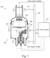
- FIG. 1 illustrates an X-ray tube 100 comprising a plurality of quantum sensors 102 positioned in use to monitor an operational parameter of the X-ray tube 100.
- the plurality of quantum sensors 102 together form a tube sensor arrangement 104, in which the quantum sensors 102 are distributed around a housing 106 of the X-ray tube 100, being stacked in an array of rings for cylindrical coverage.
- the housing 106 houses a rotating anode 108 and a cathode 110, among other components, as is known in the art.
- a power supply 112 supplies the tube 100 with power via a tube supply voltage and a grid supply voltage.
- a further voltage (not shown) controls the speed of rotation of the anode.
- a tube monitoring system 150 receives sensor signals 114 from the quantum sensors 102 and processes the sensor signals 114 to generate output signals, such as that shown at 116, for health monitoring and/or feedback control of the X-ray tube 100. It will be understood that the tube monitoring system 150 is illustrated schematically in FIG. 1 and that it could be located inside or outside the generator. The tube monitoring system 150 receives signals from the quantum sensors 102 via an optic fiber bundle (not shown).
- Electromagnetic fields generated by the X-Ray tube 100 are monitored by the tube monitoring system 150 using the quantum sensors 102. Although six sensors are illustrated in FIG. 1 , it will be understood that one such sensor is sufficient, while a plurality of quantum sensors may be used for denoising and for enhanced assessment of signal components.
- the monitoring system 150 may be configured to undertake analysis, for example in real time, of the detected signals from the sensors 102 to determine absolute E-H fields (electric and magnetic fields), dynamic currents, and/or drifts of the tube 100 (for example via electric field changes in the detected electromagnetic radiation).
- the tube monitoring system 150 may process the multi-sensor signal, e.g., with a dynamic mode decomposition, to filter out different spatiotemporal components which can be used for example for predictive maintenance or to filter out an anode rotation speed signal.
- the tube monitoring system 150 comprises a dedicated sensor for monitoring anode rotation speed.
- the monitoring system 150 may be configured to monitor health of the X-ray tube 100 and optionally also to report on performance and/or field behavior, pertaining for example to electric field quality and electromechanical vibrational spectra. This may involve producing automated reports with time stamps, possible conjectures of causes, and recommendations for further action to the operating staff (e.g. a maintenance call, or a restart of the system).
- the monitoring system 150 decomposes the sensor signals from the multi-sensor setup using dynamic mode decomposition (DMD), or alternatively using windowed Fourier transform. Peaks in the attained spectra are associated with different electromechanical modes and vibrations of the monitored tube 100.
- the tube monitoring system 150 in this example comprises a classifier trained to identify and label peaks (e.g. in the anode rotation frequency) based on learned tolerated peak widths and shapes.
- spectral information e.g., measured and desired shape
- information used to train the classifier like presumed source (anode rotation) and possible problems causing the observed spectral changes (which can be determined by a second classifier, like a convolutional neural network, trained with different spectra associated with known problems).
- the second classifier is trained using training data comprising the spectra measured or simulated from for example a misaligned anode actuator, labeled for example as belonging to the class "misaligned anode actuator".
- the monitoring system 150 is configured to use quantum sensing for predictive/corrective maintenance in relation to the X-ray tube 100.
- Temporal analysis involving for example comparisons to previous time windows can facilitate predictive maintenance.
- the sensor signals are analyzed using a sliding window approach to monitor drifts or other changes in the sensed field. Such changes may indicate approaching failure modes, allowing more significant damage by alerting personnel about recommended maintenance.
- the timeframes are multiplied with a Hamming window and Fourier transformed.
- Rectifying the spectra (taking the magnitude) resolves phase alignment issues. Then, the spectra are subtracted from each other. If differences exceed thresholds of acceptable variance within healthy operation, the tube monitoring system 150 indicates this, for example as part of a report. Thresholds can be exceeded, for example if the difference spectrum contains too much total power (squared integral) or too prominent peaks (local thresholds). Acceptable thresholds are learned or chosen empirically based on a calibration measurement in healthy operation. The monitoring system 150 may also output the spectra of the two timeframes as part of the report.
- a trained machine learning model (such as a recurrent neural network or decision tree) is used by the monitoring system 150 to classify sensor signals as relating to normal or abnormal operation or to detect drifts or changes in anode parameters, and optionally also to provide automated reporting and alerts.
- the tube monitoring system 150 comprises a generative AI model based on a transformer architecture (with encoders, decoders and attention) which learns the sensor signal spectra corresponding to different modes of healthy operation, generates a prediction of a healthy spectrum and compares it to actually measured spectra. Training is carried out with sensor recordings during healthy operation (e.g.
- the tube monitoring system 150 uses the generative AI model to translate the tube settings in real time to expected sensor spectra (for healthy operation), and compares the measured spectra to the predicted spectra. Differences are reported in a summary containing the spectra and optionally also classifier outputs on the spectral changes, suggesting possible failure modes or deterioration stages.
- the classifiers e.g. convolutional neural networks
- the CNN which receives the differences between the Fourier magnitude spectra of the predicted and the measured sensor signals, learns acceptable difference spectra for the specific tube 100. In-factory measurements with critically aged or faulty tubes and sensor spectra associated with further classes of failure or aging are included in the training data.
- the trained CNN provides class probabilities for a new input spectrum (or spectral difference to the predicted signal).
- the tube monitoring system 150 uses a support vector machine or decision tree classification, receiving the difference spectra as input features and machine diagnosis labels as output (e.g. healthy, aging stage 2, failure mode 5, etc.).
- classification is replaced or supplemented by a threshold-based method, as described elsewhere herein, based on the difference spectrum between predicted and measured signals.
- RNN recurrent neural network
- a second output is produced: a latent vector describing the previous state, as additional input to the next time step, in which the next time window is processed.
- the RNN may be learned to output warning notifications if the running analysis yields timeframes that deviate from normal operational signal evolutions. This is trained with data as for the classifiers described herein.
- Training data for unsupervised learning with generative AI (transformer) models as described herein may comprise one or more recordings of healthy machine state as input and output, with the task of predicting the running continuation of the signal at different time points.
- Training data for supervised learning with classifiers (CNN, RNN, SVM, or other) as described herein may comprise two consecutive sensor signal time windows (for example their Fourier magnitude spectra) as input with classification of corresponding machine state (e.g., healthy, aging stage 2, failure mode 5, etc.) as output.
- the classifier is trained with difference spectra between two timeframes of sensor signals, or between a measured time frame and a predicted time frame, as described herein.
- the input may comprise the two spectra, instead of the difference spectrum (especially in the case of an RNN).
- Training data for supervised learning may alternatively comprise one timeframe to be processed and classified at a time, using e.g. K-means clustering.
- K-means clustering In this example, during training, sensor recordings from different machine operation stages are fed to the classifier, specifically their Fourier magnitude spectra or DMD modes and eigenvalues (the latter in the multi-sensor setup). With K classes of operation modes (healthy, different aging stages and failure modes), the spectra are clustered by their similarity to previous spectra, determining a distance to each cluster. If a new recording is closest to the healthy cluster, but unusually far away, it could be flagged or reported.
- the certainty of the clustering classification can be interpreted from the distance to its closest cluster. Above a defined threshold, new recordings too far from a previously identified cluster can be flagged as uncertain and reported (especially with prolonged heightened uncertainty, associated with a drift of the cluster centroids, which can also be reported if exceeding thresholds).
- the tube monitoring system 150 is configured to use Doppler shifts for predictive and/or corrective maintenance. Doppler shifts may indicate a loose or misaligned actuator axis, for example.
- the tube monitoring system 150 in this example is configured to detect vibrations in the tube 100 where there should not be any (based on spectral analysis and comparison with target spectra to identify Doppler-related peak broadening).
- the tube 100 may be tuned in manufacturing to produce minimal Doppler broadening of the peaks associated with electromechanical vibrations, which are preferably kept to a minimum for energy saving and long lifetime, since vibrations usually dissipate energy and impose strain.
- FIG. 2 illustrates the X-ray tube 100 comprising the monitoring system 150 in a second example of the present disclosure.
- a quantum sensor 102 is positioned to monitor rotation of the anode 108 of the X-ray tube 100.
- the monitoring system 150 receives signals from the quantum sensor 102, with FIG. 2 further illustrating the optical fibers 118 provided for that purpose.
- the anode 108 and (metal) housing 106 usually have different electric potentials (the anode 108 has generally a more positive potential than the housing 106), with the two components thereby forming a capacitor.
- the tube sensing arrangement in this example comprises a capacitor plate 120 on the outside of the housing 106, with a weak voltage 122 applied with respect to the housing 106, such that the capacitor plate 120 and the housing 106 together form a capacitor.
- the electric field between the housing 106 and the capacitor plate 120 is modulated by the rotation of the anode 108, assuming that the anode 108 exhibits some irregularity in its structure (i.e., a rotationally asymmetric structure).
- the quantum sensor 102 measures the electric and magnetic field variations in the capacitor, which are analyzed by the monitoring system 150. To that end, the quantum sensor 102 is positioned between the capacitor plate 120 and the housing 106. By processing the quantum sensor signal, the monitoring system 150 determines anode rotation speed, expressed for example in terms of rotations per minute (RPM).
- the monitoring system 150 may filter out harmonic components relating to the anode rotation speed.
- shielding hardware like a Faraday cage may be constructed around the external capacitor and other tube parts to isolate external electromagnetic radiation noise. Electric or magnetic fields generated by the rotor powering the anode rotation can be measured and analyzed.
- the quantum sensor 102 may be placed closer to the stator than to the anode. A mixed signal is thereby picked up, containing the rotor frequency and the stator frequency, separated by the so-called "slip frequency". The stator frequency can be filtered from the mixed signal to extract the anode rotation speed.
- a quantum sensor may be located close to the generator or other locations as a reference to detect noise. The signals from the quantum sensors may then be fed to circuitry, such as a trained neural network, for denoising the signal.
- a second quantum sensor is placed opposite (180 degrees) to the first quantum sensor 102 to detect symmetrical anode capacitive defects.
- the detected signals are filtered and correlated either digitally or by a bridge circuit.
- a plurality of quantum sensors are placed at various locations, optionally replacing the capacitor-based sensing arrangement of FIG. 2 , to measure the leaked electromagnetic radiation from the driving electromotor. If the detected spectral power increases, for example outside normal operational bounds, or if certain peaks arise that were not present during healthy operation, the monitoring system 150 may indicate the need for predictive/corrective maintenance. For example, if new vibrational resonances arise, this may indicate structural changes or parts becoming loose.
- the monitoring system 150 may then perform active feedback control of the anode rotation speed via a driving voltage.
- the measured rotation speed of the anode is used as a feedback parameter to tune the voltages driving the rotation. More particularly, the voltages/currents controlling the actuator which rotates the anode can be controlled via a comparison between the target anode rotation speed Vt in a certain operation mode and the anode rotation speed V m actually measured by the sensors. This may comprise reducing anode rotation speed during idle times for green footprint improvement.
- the monitoring system 150 may perform health monitoring based on the sensor signals, which in this example represent anode rotation, for the purposes of predictive and/or corrective maintenance of the anode or components driving its rotation. For example, angulation changes in the anode's rotation axis, nutation, vibrations, and other abnormalities that produce unusual field modulations can be detected by the monitoring system 150, using for example a trained machine learning model such as a recurrent neural network or decision tree.
- a trained machine learning model such as a recurrent neural network or decision tree.
- the monitoring system 150 may extract the periodic temporal modulation of the field caused by the anode at different processing stages of the signal. Depending on the model of the tube 100, optimal sensor location may vary and may be determined experimentally.
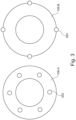
- FIG. 3 illustrates two examples of the anode 108 that may be used in the X-ray tube 100 of FIG. 1 or FIG. 2 .
- the anode 108 Via structuring of the anode 108, whether through holes, recesses, or bumps along the circumference, the anode 108 is better able to produce detectable modulations in the electric field within the tube 100 to be detected by the quantum sensors 102.
- Shown in FIG. 3 is a first example of a modified anode 108-A comprising a distribution of holes 302, along with a second example of a modified anode 108-B comprising bumps 304 distributed along its periphery.
- the shape, size, number, and position of the modifications can vary. In principle, one modification is enough to produce a periodic modulation.
- the skin depth of the X-ray tube housing 106 does not present a problem in the relevant frequency range of anode rotation (typically below 1 kHz). Nonetheless, the anode structuring can be adjusted to improve signal penetration through the housing 106 by comprising a more modifications to increase the modulation frequency.
- FIG. 4 illustrates an exemplary computing system 800 that can be used in accordance with the systems and methods disclosed herein.
- the computing system 800 may form part of or comprise any desktop, laptop, server, or cloud-based computing system.
- the computing system 800 includes a processor 802 that executes instructions that are stored in a memory 804.
- the instructions may be, for instance, instructions for implementing functionality described as being carried out by one or more components described herein or instructions for implementing one or more of the methods described herein.
- the processor 802 may access the memory 804 by way of a system bus 806.
- the memory 804 may also store conversational inputs, scores assigned to the conversational inputs, etc.
- the computing system 800 additionally includes a data store 808 that is accessible by the processor 802 by way of the system bus 806.
- the data store 808 may include executable instructions, log data, etc.
- the computing system 800 also includes an input interface 810 that allows external devices to communicate with the computing system 800. For instance, the input interface 810 may be used to receive instructions from an external computer device, from a user, etc.
- the computing system 800 also includes an output interface 812 that interfaces the computing system 800 with one or more external devices. For example, the computing system 800 may display text, images, etc. by way of the output interface 812.
- the external devices that communicate with the computing system 800 via the input interface 810 and the output interface 812 can be included in an environment that provides substantially any type of user interface with which a user can interact.
- user interface types include graphical user interfaces, natural user interfaces, and so forth.
- a graphical user interface may accept input from a user employing input device(s) such as a keyboard, mouse, remote control, or the like and provide output on an output device such as a display.
- a natural user interface may enable a user to interact with the computing system 800 in a manner free from constraints imposed by input device such as keyboards, mice, remote controls, and the like. Rather, a natural user interface can rely on speech recognition, touch and stylus recognition, gesture recognition both on screen and adjacent to the screen, air gestures, head and eye tracking, voice and speech, vision, touch, gestures, machine intelligence, and so forth.
- computing system 800 may be a distributed system. Thus, for instance, several devices may be in communication by way of a network connection and may collectively perform tasks described as being performed by the computing system 800.
- Computer-readable media include computer-readable storage media.
- Computer-readable storage media can be any available storage media that can be accessed by a computer.
- such computer-readable storage media can comprise FLASH storage media, RAM, ROM, EEPROM, CD-ROM or other optical disk storage, magnetic disk storage or other magnetic storage devices, or any other medium that can be used to carry or store desired program code in the form of instructions or data structures and that can be accessed by a computer.
- Disk and disc include compact disc (CD), laser disc, optical disc, digital versatile disc (DVD), floppy disk, and Blu-ray disc (BD), where disks usually reproduce data magnetically and discs usually reproduce data optically with lasers.
- BD Blu-ray disc
- Computer-readable media also includes communication media including any medium that facilitates transfer of a computer program from one place to another.
- a connection for instance, can be a communication medium.
- the software is transmitted from a website, server, or other remote source using a coaxial cable, fiber optic cable, twisted pair, digital subscriber line (DSL), or wireless technologies such as infrared, radio, and microwave
- coaxial cable, fiber optic cable, twisted pair, DSL, or wireless technologies such as infrared, radio and microwave
- the coaxial cable, fiber optic cable, twisted pair, DSL, or wireless technologies such as infrared, radio and microwave
- the functions described herein can be performed, at least in part, by one or more hardware logic components.
- illustrative types of hardware logic components include Field-programmable Gate Arrays (FPGAs), Program-specific Integrated Circuits (ASICs), Program-specific Standard Products (ASSPs), System-on-a-chip systems (SOCs), Complex Programmable Logic Devices (CPLDs), etc.
- the invention may be implemented by means of hardware comprising several distinct elements, and/or by means of a suitably programmed processor.
- the device claim enumerating several means several of these means may be embodied by one and the same item of hardware.
- Measures recited in mutually different dependent claims may advantageously be used in combination. Any reference signs in the claims cannot be construed as limiting the scope.
Landscapes
- Health & Medical Sciences (AREA)
- General Health & Medical Sciences (AREA)
- Toxicology (AREA)
- X-Ray Techniques (AREA)
Abstract
Predictive maintenance in X-ray imaging aims to determine the condition of the tube and predict service intervals and remaining lifetime based on signals recorded by sensors. Obtaining reliable sensor signals in the adverse conditions prevailing in the tube remains a challenge. There is therefore provided a monitoring system for an X-ray tube (100), the monitoring system (150) being configured to receive a sensor signal (114) from a tube sensor arrangement (104), wherein the tube sensor arrangement (104) comprises a quantum sensor (102) positioned in use to monitor an operational parameter of the X-ray tube (100), the monitoring system being further configured to process the sensor signal (114) to generate an output signal (116) for health monitoring or feedback control of the X-ray tube (100). The use of quantum sensors facilitates monitoring systems for X-ray tubes and generators which are non-interfering, non-coupling, ultra-high sensitivity, ultra-small and light, and robust.
Description
- The invention relates to systems and methods for monitoring X-ray tubes.
- Predictive maintenance in X-ray imaging aims to determine the condition of the tube and predict service intervals and remaining lifetime based on signals recorded by sensors. Obtaining reliable sensor signals in the adverse conditions prevailing in the tube remains a challenge.
- It is an object of the invention to better address one or more of these concerns. The invention is defined by the independent claims. The dependent claims define advantageous embodiments.
- A first aspect of invention provides a monitoring system for an X-ray tube, the monitoring system being configured to receive a sensor signal from a tube sensor arrangement, wherein the tube sensor arrangement comprises a quantum sensor positioned in use to monitor an operational parameter of the X-ray tube, the monitoring system being further configured to process the sensor signal to generate an output signal for health monitoring or feedback control of the X-ray tube.
- Various types of quantum sensor may be used in the tube sensor arrangement. For example, the quantum sensor may comprise a nitrogen-vacancy (NV) diamond sensor, i.e., a quantum sensor which uses solid-state qubits embedded within the nitrogen-vacancy center of a diamond. Such sensors operate with a D.C. to GHz bandwidth using diamonds in the µm size range and have been shown to function from 4-625 Kelvin, in magnetic fields of up to 8.3 T, and pressures up to 13.6 GPa. The Rydberg state in such sensors may be prepared with a green laser. Additionally or alternatively, the tube sensor arrangement may comprise an optically pumped magnetometer (OPM), i.e., a quantum sensor which uses a highly excited atomic gas for field probing based on the quantized energy levels which are altered by external fields. Such sensors comprise a small glass chamber (in the mm size range) filled with an alkali metal gas (e.g. Rubidium). Rydberg states in such sensors may be prepared and probed with two lasers (e.g. blue and near-infrared). It will be understood that the types of quantum sensors as described herein are non-limiting and that other types of quantum sensors may be developed in the future which would provide the same functionality. It should additionally be noted that the monitoring system may comprise one or more traditional sensors (e.g., MEMS, electromagnetic sensors) alongside the quantum sensor.
- The tube sensor arrangement may comprise one or more laser sources for preparing the quantum sensor and/or for probing the quantum sensor to extract the signal to be monitored. For example, in the case of the OPM, laser light absorption changes with the local electromagnetic field, which interacts with the Rydberg state superposition prepared by a first laser (driving a Rabi oscillation) and probed by a second laser.
- The tube sensor arrangement may further comprise an optical fiber for conveying laser light to and/or from the quantum sensor. The quantum sensor can be read out with laser light. The optical signal may be digitized (via optical-to-digital conversion circuitry) before being processed by the monitoring system to generate the output signal. Real-time radiative field information (transmitted at light speed) at a high bandwidth is available from the quantum sensor, so the digitization is preferably performed late, i.e., by optical-to-electrical conversion circuitry which resides outside of the X-ray tube, for example in the X-ray generator. The optical-to-electrical conversion circuitry may be viewed as forming part of the tube sensor arrangement and/or part of the monitoring system, depending on the implementation.
- The tube sensor arrangement may comprise a set of quantum sensors distributed within or around the X-Ray tube or an X-ray generator that comprises the X-ray tube. In one example, the tube sensor arrangement comprises a quantum sensor within the X-ray tube itself, which allows for sensitive surveillance of electromechanical parameters yielding real-time motion vector fields. For example, a quantum sensor may be attached or attachable to a housing of the X-ray tube. Additionally or alternatively, the tube sensor arrangement may comprise a quantum sensor attached or attachable to a housing of the X-ray generator. In one particular example, the tube sensor arrangement comprises a plurality of quantum sensors arranged in an array of rings for cylindrical coverage around an axis of the X-ray tube.
- Various operational parameters of the X-ray tube may be monitored and/or controlled using the a quantum sensor. In one example, the electric and/or magnetic field generated by the X-ray tube is monitored and/or controlled using the a quantum sensor. Other parameters like electrical current or voltage may be determined indirectly using the a sensor signal. For example, further processing of the detected signals from the tube sensor arrangement may be performed to monitor and/or control one or more of: dynamic changes in motor/field-generating currents (enabling an active feedback loop which adjusts currents for exact fields); dynamic ramp up/down (e.g., of anode rotation speed); changes in orientation of motor rotation axis; and (electromechanical) drifts of the X-ray tube caused for example by temperature effects.
- In one example, the tube sensor arrangement comprises a quantum sensor for monitoring rotation of an anode of the X-ray tube. The anode and tube housing typically have different electric potentials, thereby forming a capacitor. The tube sensor arrangement may comprise a capacitor plate to be positioned adjacent to a housing of the X-ray tube such that an electric field between the housing and the capacitor plate is modulated by the rotation of the anode. The quantum sensor is arranged to measure the modulated electric field between the housing and the capacitor plate. The monitoring system is configured to determine anode rotation speed via the signal output by the quantum sensor and/or to perform abnormality detection monitoring. In this example, the anode may comprise a structural modification designed to produce a detectable, e.g. periodic, modulation of the electric field in the capacitor. Alternatively, manufacturing defects or natural imperfections in the anode may give rise to a detectable modulation of the electric field. The tube sensor arrangement may comprise a further quantum sensor configured to produce a reference signal which is usable for denoising the signal from the a quantum sensor for monitoring the rotation of the anode. For example, the reference sensor can be arranged on an opposite side of the tube housing to the capacitor sensor. The monitoring system may be further configured to filter the stator frequency from the capacitor sensor signal to extract the anode rotation speed.
- The monitoring system may be configured to process the sensor signal in various ways to generate an output signal. For example, the output signal may be used for health monitoring. In one example, processing the sensor signal comprises performing predictive maintenance on the basis of the sensor signal. For example, the sensor signal may enable the monitoring system to determine the condition of in-service equipment in order to estimate when maintenance should be performed. Additionally or alternatively to predictive maintenance, processing the sensor signal may comprise identifying a need for corrective maintenance on the basis of equipment condition as represented by the one sensor signal. The monitoring may be configured to generate, as the output signal for health monitoring, an equipment state signal indicating a condition of a component of the X-ray tube, wherein the equipment state signal is usable to perform predictive and/or corrective maintenance in relation to the X-ray tube. The equipment state signal may indicate a condition of the anode of the X-ray tube. In one particular example, the equipment state signal indicates a speed of the rotation of the anode as being representative of the condition of the anode (in the case that the tube sensor arrangement comprises a sensor for monitoring anode rotation).
- The monitoring system may be configured to analyze the sensor signal to monitor drift or other changes in an electric field sensed by the quantum sensor (which may be indicative of emerged or emerging failure modes) and to determine the condition of the component of the X-ray tube based on the monitored drift. The monitoring system may be configured to monitor drift or other changes using a sliding window approach. Using the sliding window approach may comprise comparing signal values in a first time window with signal values in a second, previous time window of comparable, e.g. equal, length. Additionally or alternatively, the monitoring system may be configured to monitor drift or other changes using artificial intelligence (AI).
- In one AI-based example of drift monitoring, an autoregressive model takes as input a previous timeframe and predicts the continuation (using, for example, a transformer architecture with encoders, decoders, and attention mechanism on spectral components, trained with recordings of healthy machines). The similarity between the predicted continuation and the recorded sensor signal is compared (e.g., comparing spectral differences or with cosine similarity of latent representations thereof). When deviations are detected (e.g., those above a significance threshold), these may be flagged and/or reported (by outputting for example timepoints, spectra before and after with notification of changes therein, optionally interpreted by a classifier that was trained with various degradation and failure scenarios and their corresponding spectral changes). The classification of spectral changes may provide an estimate of remaining useful lifetime and probable failure scenarios.
- Additionally or alternatively, a correlation function may be used to monitor drift or other changes in the sensor signal over time. For example, the scalar product of field variations around the mean value over two time windows can be compared (optionally after an initial phase alignment, to avoid phase alignment issues and drifts). More particularly, the Fourier-transformed field variations throughout the timeframes may be compared for example by calculating the difference between the spectra, optionally using a prepended smoothing and/or rectifying operation. Once again, threshold-based flagging may be used, i.e., when the correlation shows a substantial change or the difference spectrum exceeds a defined power threshold locally or integrated over all frequencies. The difference spectrum approach may be combined with a classifier trained with different degradation scenarios and their sensor signal measurements, to learn which degradation and failure modes cause which spectral changes (for example, over timeframes of a chosen length, e.g. 5 minutes, with two consecutive timeframes - a 10 minute total interval - running with time in a sliding window manner).
- Additionally or alternatively, drift or other changes may be monitored using a dynamic mode decomposition (DMD) or a variational mode decomposition (VMD) prepended to an AI classifier or spectral difference analysis. These linear signal decomposition techniques identify dominant frequencies with time-varying amplitudes (DMD is a linear regression approach and VMD is optimization-driven). This has a denoising effect and performs well in time-frequency analyses, yielding independent modes at different frequencies while indicating how they change over time. The attained eigenvalues and eigenvectors may be monitored in real-time with a classifier or running mean approach (flag an event if the running mean over a time-period changes significantly). Classifiers may be trained with the modes (eigenvectors and eigenvalue time evolutions) arising with different degradation modes or failures. In one particular example, multi-resolution DMD is used to advantageously yield a plurality of oscillation modes sorted by slow and fast evolving states hierarchically in a mode matrix. This may be fed to a convolutional neural network for classification of modes indicating faults or degradation stages. Significant mode changes may be reported even if classification does not identify a specific indicator.
- Additionally or alternatively, the processing may comprise performance monitoring on the basis of the signal. Performance monitoring may comprise monitoring field behavior, pertaining to electric field quality and/or electromechanical vibrational spectra, for example, using any of the techniques described herein.
- Additionally or alternatively, processing the sensor signal to generate the output signal may comprise performing self-tuning. That is, the monitoring system may be configured to generate, as the output signal for feedback control, a control signal for implementing feedback control of an operational parameter of the X-ray tube. For example, the sensor signal may be used to implement active feedback control of parameters of the X-ray tube and/or X-ray generator, for example electrical parameters (e.g., currents, voltages, actuators), via a feedback loop. Such electrical parameters may be used for various purposes, for example in connection with the control of a cooling system of the tube, access control to the diagnostic system, or power supply to calculate required energy to be delivered, as is known in the art. In the case that the tube sensor arrangement comprises a sensor for monitoring anode rotation speed, the monitoring system may be configured to generate, as the output signal, a control signal for implementing feedback control of the speed of the rotation of the anode via one or more driving voltages. In the case that the monitoring system is further configured to control the X-ray tube and/or the X-ray generator, it may be appropriately described as a monitoring and control system. In one example, the monitoring system may use AI to translate field changes to generator control parameters. In one AI-based example, a neural network is trained to predict a driving current (A) for a desired anode rotation speed (V). The relation A(V) depends on environmental variables like ambient temperature (T) and ambient pressure (P), which can be measured with additional sensors and fed to the neural network as additional input. To train the neural network, the anode rotation speed V resulting from driving current A is recorded in a calibration mode, sweeping different currents under different temperature and pressure conditions using a healthy X-ray tube. The recordings at different temperatures T and pressures P for different rotation speeds V are then used for training the neural network (with V,T,P as input and A as output) to learn the function A(V,T,P), saved within the trained model weights. During the training with different relevant V, T, and P ranges, backpropagation adjusts the weights of the neural network to learn the connection between a desired rotation speed V and the necessary driving current A. Such computation of the driving current necessary for different anode rotation speeds may be useful for the energy saving aspect and understanding of the system's efficiency.
- The so trained model may be used in both health monitoring and feedback control. In terms of health monitoring, the model may provide a system health rating based on the deviation between the anode rotation speed measured using the quantum sensor and that used by the model. If the system has impurities, it is expected to yield deviations of the resulting rotation speeds V for various currents A. The larger the deviations of the measured V from the model input V, the more problematic the state of the machine (diagnosis can be made for example using a sweep over different values of V).
- For feedback control, a real-time feedback loop may be implemented based on the difference of the speed measured by the quantum sensor (Vm) and the desired target speed (Vt). The driving current A is varied in real time with the increment per timestep dA = k*(dA/dV)*(Vt - Vm) if the speed difference (Vt - Vm) exceeds a threshold. The adjustment rate k may be tuned empirically to a small value for slow current adjustments and (dA/dV) can be derived from the above-described learned relation A(V) or estimated as the reciprocal of the measured differential dV/dA with a small current adjustment dA.
- The monitoring system may comprise functionality for reporting, visualization, and notification of any of the parameters directly or indirectly monitored using the techniques described herein. That functionality may be implemented by software, for example. For example, reports produced by the monitoring system may be collected by the vendor for post-market surveillance.
- The monitoring system may comprise processing circuitry for carrying out the processing. The processing circuitry may be implemented using hardware, firmware, and/or software configured to perform any of the operations or algorithms described herein. Hardware may comprise, singly or in any combination, hardwired circuitry, programmable circuitry such as computer processors comprising one or more individual instruction processing cores, or state machine circuitry. Firmware may be embodied as code, instructions and/or data stored or hardcoded in memory devices (e.g., non-volatile memory devices). Software may be embodied as a software package, code, instructions and/or data recorded on a transitory or non-transitory computer readable storage medium.
- The monitoring system may be provided as a standalone product to be retrofitted to an existing X-ray tube. There is therefore also provided by the present disclosure an X-ray tube comprising the monitoring system of the first aspect. Further provided is a medical imaging system comprising the monitoring system of the first aspect. The monitoring system in any case may comprise the tube sensor arrangement.
- The monitoring system based on quantum sensing as described herein is applicable to any X-ray tube, especially those having rotating anodes, including X-ray tubes used for CT-systems having rotating gantries.
- In a second aspect of invention, there is provided a method of monitoring an X-ray tube, the method comprising receiving a sensor signal from a tube sensor arrangement, wherein the tube sensor arrangement comprises a quantum sensor positioned in use to monitor an operational parameter of the X-ray tube, and processing the sensor signal to generate an output signal for health monitoring or feedback control of the X-ray tube.
- Any optional features or subaspects of the first aspect may apply to the second aspect, mutatis mutandis.
- The method of the second aspect may be computer implemented.
According to a third aspect, there is provided a computing system configured to perform the method of the second aspect. - According to a fourth aspect, there is provided a computer program (product) comprising instructions which, when executed by a computing system, enable or cause the computing system to perform the method of the second aspect. The computer program product may be software available for download from a server, e.g., via the internet. Alternatively, the computer program product may be a computer-readable (storage) medium comprising instructions which, when executed by a computing system, enable or cause the computing system to perform the method of the second aspect. The computer-readable medium may be transitory or non-transitory, volatile or non-volatile. The computer program product may be an optical storage medium or a solid-state medium, which may or may not be supplied together with or as part of other hardware.
- The use of quantum sensors facilitates monitoring systems for X-ray tubes and generators which are non-interfering, non-coupling, ultra-high sensitivity, ultra-small and light, high bandwidth, and robust. The use of quantum sensors enables the monitoring system to be readily built into new or existing X-ray tubes and generators. The use of quantum sensors may mitigate the proliferation of different types of sensors which currently exist in tube monitoring systems, such as gyro, current, X-ray, MEMS, piezo, and ultrasound sensors. Use of quantum sensors advantageously facilitates monitoring of the anode rotation speed, a parameter which is otherwise challenging to monitor. The high bandwidth sensitivity of quantum sensors allows higher order vibrational modes to be taken into account, which is advantageous for predictive/corrective maintenance and degradation forecasting for remaining lifetime predictions. Performing health monitoring as described herein (including predictive/corrective maintenance) may provide for early prediction of failure while increasing patient safety and lifetime of X-ray tubes and limiting downtime. Habitually problematic components may be identified and improved.
- Performing feedback control as described herein (including tuning) may provide for enhanced image quality and improved fidelity of attained X-ray spectra, by virtue for example of the electric fields being tuned to more exact values taking into account manufacturing imperfections and variations. Controlling anode rotation speed may facilitate distribution of electron irradiation thereby keeping the anode cool.
- The term "determining", as used herein, encompasses a wide variety of actions, and may comprise, for example, calculating, computing, processing, deriving, investigating, looking up (e.g., looking up in a table, a database or another data structure), ascertaining, and the like. Also, "determining" may comprise receiving (e.g., receiving information), accessing (e.g., accessing data in a memory), and the like. Also, "determining" may comprise resolving, selecting, choosing, establishing and the like.
- The indefinite article "a" or "an" does not exclude a plurality. In addition, the articles "a" and "an" as used herein should generally be construed to mean "one or more" unless specified otherwise or clear from the context to be directed to a singular form.
- Unless specified otherwise, or clear from the context, the phrases "one or more of A, B and C", "at least one of A, B, and C", and "A, B and/or C" as used herein are intended to mean all possible permutations of one or more of the listed items. That is, the phrase "A and/or B" means (A), (B), or (A and B), while the phrase "A, B, and/or C" means (A), (B), (C), (A and B), (A and C), (B and C), or (A, B, and C).
- The term "comprising" does not exclude other elements or steps. Furthermore, the terms "comprising", "including", "having" and the like may be used interchangeably herein.
- The invention may include one or more aspects, examples or features in isolation or combination whether specifically disclosed in that combination or in isolation. Any optional feature or sub-aspect of one of the above aspects applies as appropriate to any of the other aspects.
- The above-described aspects will become apparent from, and elucidated with, reference to the detailed description provided hereinafter.
- A detailed description will now be given, by way of example only, with reference to the accompanying drawings, in which:
-
FIG. 1 illustrates an X-ray tube comprising a monitoring system according to a first example of the present disclosure; -
FIG. 2 illustrates an X-ray tube comprising a monitoring system according to a second example of the present disclosure; -
FIG. 3 illustrates to two examples of anodes comprising structural modifications for use with the X-ray tube ofFIG. 1 orFIG. 2 ; and -
FIG. 4 illustrates a computing system that can be used in accordance with the systems and methods disclosed herein. -
FIG. 1 illustrates anX-ray tube 100 comprising a plurality ofquantum sensors 102 positioned in use to monitor an operational parameter of theX-ray tube 100. The plurality ofquantum sensors 102 together form atube sensor arrangement 104, in which thequantum sensors 102 are distributed around ahousing 106 of theX-ray tube 100, being stacked in an array of rings for cylindrical coverage. Thehousing 106 houses arotating anode 108 and acathode 110, among other components, as is known in the art. Apower supply 112 supplies thetube 100 with power via a tube supply voltage and a grid supply voltage. A further voltage (not shown) controls the speed of rotation of the anode. - A
tube monitoring system 150 receives sensor signals 114 from thequantum sensors 102 and processes the sensor signals 114 to generate output signals, such as that shown at 116, for health monitoring and/or feedback control of theX-ray tube 100. It will be understood that thetube monitoring system 150 is illustrated schematically inFIG. 1 and that it could be located inside or outside the generator. Thetube monitoring system 150 receives signals from thequantum sensors 102 via an optic fiber bundle (not shown). - Electromagnetic fields generated by the
X-Ray tube 100 are monitored by thetube monitoring system 150 using thequantum sensors 102. Although six sensors are illustrated inFIG. 1 , it will be understood that one such sensor is sufficient, while a plurality of quantum sensors may be used for denoising and for enhanced assessment of signal components. Themonitoring system 150 may be configured to undertake analysis, for example in real time, of the detected signals from thesensors 102 to determine absolute E-H fields (electric and magnetic fields), dynamic currents, and/or drifts of the tube 100 (for example via electric field changes in the detected electromagnetic radiation). Thetube monitoring system 150 may process the multi-sensor signal, e.g., with a dynamic mode decomposition, to filter out different spatiotemporal components which can be used for example for predictive maintenance or to filter out an anode rotation speed signal. In one embodiment, described further below, thetube monitoring system 150 comprises a dedicated sensor for monitoring anode rotation speed. - The
monitoring system 150 may be configured to monitor health of theX-ray tube 100 and optionally also to report on performance and/or field behavior, pertaining for example to electric field quality and electromechanical vibrational spectra. This may involve producing automated reports with time stamps, possible conjectures of causes, and recommendations for further action to the operating staff (e.g. a maintenance call, or a restart of the system). - In one health monitoring example, the
monitoring system 150 decomposes the sensor signals from the multi-sensor setup using dynamic mode decomposition (DMD), or alternatively using windowed Fourier transform. Peaks in the attained spectra are associated with different electromechanical modes and vibrations of the monitoredtube 100. Thetube monitoring system 150 in this example comprises a classifier trained to identify and label peaks (e.g. in the anode rotation frequency) based on learned tolerated peak widths and shapes. If a peak deviates from the learned healthy shape, this may be reported, for example by providing spectral information (e.g., measured and desired shape) and information used to train the classifier, like presumed source (anode rotation) and possible problems causing the observed spectral changes (which can be determined by a second classifier, like a convolutional neural network, trained with different spectra associated with known problems). The second classifier is trained using training data comprising the spectra measured or simulated from for example a misaligned anode actuator, labeled for example as belonging to the class "misaligned anode actuator". - In another health monitoring example, the
monitoring system 150 is configured to use quantum sensing for predictive/corrective maintenance in relation to theX-ray tube 100. Temporal analysis involving for example comparisons to previous time windows can facilitate predictive maintenance. The sensor signals are analyzed using a sliding window approach to monitor drifts or other changes in the sensed field. Such changes may indicate approaching failure modes, allowing more significant damage by alerting personnel about recommended maintenance. In one non-limiting example of a sliding window approach, two time windows of length T=n*dT (each holding n signal samples spaced dT apart) are selected from the running sensor signal (e.g., two consecutive timeframes with no overlap, totaling a snippet of length 2T). The timeframes are multiplied with a Hamming window and Fourier transformed. Rectifying the spectra (taking the magnitude) resolves phase alignment issues. Then, the spectra are subtracted from each other. If differences exceed thresholds of acceptable variance within healthy operation, thetube monitoring system 150 indicates this, for example as part of a report. Thresholds can be exceeded, for example if the difference spectrum contains too much total power (squared integral) or too prominent peaks (local thresholds). Acceptable thresholds are learned or chosen empirically based on a calibration measurement in healthy operation. Themonitoring system 150 may also output the spectra of the two timeframes as part of the report. - In yet another health monitoring example, a trained machine learning model (such as a recurrent neural network or decision tree) is used by the
monitoring system 150 to classify sensor signals as relating to normal or abnormal operation or to detect drifts or changes in anode parameters, and optionally also to provide automated reporting and alerts. In one particular example, thetube monitoring system 150 comprises a generative AI model based on a transformer architecture (with encoders, decoders and attention) which learns the sensor signal spectra corresponding to different modes of healthy operation, generates a prediction of a healthy spectrum and compares it to actually measured spectra. Training is carried out with sensor recordings during healthy operation (e.g. in factory) as output, along with the settings of the X-ray tube 100 (e.g., voltages and mode of operation tags) as input. During monitoring, thetube monitoring system 150 uses the generative AI model to translate the tube settings in real time to expected sensor spectra (for healthy operation), and compares the measured spectra to the predicted spectra. Differences are reported in a summary containing the spectra and optionally also classifier outputs on the spectral changes, suggesting possible failure modes or deterioration stages. The classifiers (e.g. convolutional neural networks) are trained with different tubes in factory or with thespecific tube 100 on site with sensor recordings during a prolonged period of operation (with different settings and modes, perhaps throughout a calibration run). With thetube 100 being assumed healthy at the calibration stage, the CNN, which receives the differences between the Fourier magnitude spectra of the predicted and the measured sensor signals, learns acceptable difference spectra for thespecific tube 100. In-factory measurements with critically aged or faulty tubes and sensor spectra associated with further classes of failure or aging are included in the training data. The trained CNN provides class probabilities for a new input spectrum (or spectral difference to the predicted signal). - It will be understood that the above disclosure is provided for purposes of illustration only and that variants to the described examples are conceivable. In one variant, additionally or alternatively to the use of CNNs, the
tube monitoring system 150 uses a support vector machine or decision tree classification, receiving the difference spectra as input features and machine diagnosis labels as output (e.g. healthy, aging stage 2, failure mode 5, etc.). In a further variant, classification is replaced or supplemented by a threshold-based method, as described elsewhere herein, based on the difference spectrum between predicted and measured signals. A yet further variant uses a recurrent neural network (RNN), which receives as input a timeframe of the sensor signals and outputs a classification of health, as described herein for the classifier. In this variant, a second output is produced: a latent vector describing the previous state, as additional input to the next time step, in which the next time window is processed. The RNN may be learned to output warning notifications if the running analysis yields timeframes that deviate from normal operational signal evolutions. This is trained with data as for the classifiers described herein. - Training data for unsupervised learning with generative AI (transformer) models as described herein may comprise one or more recordings of healthy machine state as input and output, with the task of predicting the running continuation of the signal at different time points. Training data for supervised learning with classifiers (CNN, RNN, SVM, or other) as described herein may comprise two consecutive sensor signal time windows (for example their Fourier magnitude spectra) as input with classification of corresponding machine state (e.g., healthy, aging stage 2, failure mode 5, etc.) as output. The classifier is trained with difference spectra between two timeframes of sensor signals, or between a measured time frame and a predicted time frame, as described herein. Alternatively, the input may comprise the two spectra, instead of the difference spectrum (especially in the case of an RNN). Training data for supervised learning may alternatively comprise one timeframe to be processed and classified at a time, using e.g. K-means clustering. In this example, during training, sensor recordings from different machine operation stages are fed to the classifier, specifically their Fourier magnitude spectra or DMD modes and eigenvalues (the latter in the multi-sensor setup). With K classes of operation modes (healthy, different aging stages and failure modes), the spectra are clustered by their similarity to previous spectra, determining a distance to each cluster. If a new recording is closest to the healthy cluster, but unusually far away, it could be flagged or reported. The certainty of the clustering classification can be interpreted from the distance to its closest cluster. Above a defined threshold, new recordings too far from a previously identified cluster can be flagged as uncertain and reported (especially with prolonged heightened uncertainty, associated with a drift of the cluster centroids, which can also be reported if exceeding thresholds).
- In one further health monitoring example, the
tube monitoring system 150 is configured to use Doppler shifts for predictive and/or corrective maintenance. Doppler shifts may indicate a loose or misaligned actuator axis, for example. Thetube monitoring system 150 in this example is configured to detect vibrations in thetube 100 where there should not be any (based on spectral analysis and comparison with target spectra to identify Doppler-related peak broadening). Thetube 100 may be tuned in manufacturing to produce minimal Doppler broadening of the peaks associated with electromechanical vibrations, which are preferably kept to a minimum for energy saving and long lifetime, since vibrations usually dissipate energy and impose strain. -
FIG. 2 illustrates theX-ray tube 100 comprising themonitoring system 150 in a second example of the present disclosure. Aquantum sensor 102 is positioned to monitor rotation of theanode 108 of theX-ray tube 100. As before, themonitoring system 150 receives signals from thequantum sensor 102, withFIG. 2 further illustrating theoptical fibers 118 provided for that purpose. Theanode 108 and (metal)housing 106 usually have different electric potentials (theanode 108 has generally a more positive potential than the housing 106), with the two components thereby forming a capacitor. The tube sensing arrangement in this example comprises acapacitor plate 120 on the outside of thehousing 106, with aweak voltage 122 applied with respect to thehousing 106, such that thecapacitor plate 120 and thehousing 106 together form a capacitor. The electric field between thehousing 106 and thecapacitor plate 120 is modulated by the rotation of theanode 108, assuming that theanode 108 exhibits some irregularity in its structure (i.e., a rotationally asymmetric structure). Thequantum sensor 102 measures the electric and magnetic field variations in the capacitor, which are analyzed by themonitoring system 150. To that end, thequantum sensor 102 is positioned between thecapacitor plate 120 and thehousing 106. By processing the quantum sensor signal, themonitoring system 150 determines anode rotation speed, expressed for example in terms of rotations per minute (RPM). - Due to high sensitivity of the
quantum sensor 102, external noise can disturb the measurement. To that end, themonitoring system 150 may filter out harmonic components relating to the anode rotation speed. Additionally or alternatively, shielding hardware, like a Faraday cage may be constructed around the external capacitor and other tube parts to isolate external electromagnetic radiation noise. Electric or magnetic fields generated by the rotor powering the anode rotation can be measured and analyzed. For this purpose, thequantum sensor 102 may be placed closer to the stator than to the anode. A mixed signal is thereby picked up, containing the rotor frequency and the stator frequency, separated by the so-called "slip frequency". The stator frequency can be filtered from the mixed signal to extract the anode rotation speed. Furthermore, a quantum sensor may be located close to the generator or other locations as a reference to detect noise. The signals from the quantum sensors may then be fed to circuitry, such as a trained neural network, for denoising the signal. - In one variant to the example shown in
FIG 2 , a second quantum sensor is placed opposite (180 degrees) to the firstquantum sensor 102 to detect symmetrical anode capacitive defects. The detected signals are filtered and correlated either digitally or by a bridge circuit. - In a further variant, a plurality of quantum sensors are placed at various locations, optionally replacing the capacitor-based sensing arrangement of
FIG. 2 , to measure the leaked electromagnetic radiation from the driving electromotor. If the detected spectral power increases, for example outside normal operational bounds, or if certain peaks arise that were not present during healthy operation, themonitoring system 150 may indicate the need for predictive/corrective maintenance. For example, if new vibrational resonances arise, this may indicate structural changes or parts becoming loose. - Having determined the anode rotation speed, the
monitoring system 150 may then perform active feedback control of the anode rotation speed via a driving voltage. The measured rotation speed of the anode is used as a feedback parameter to tune the voltages driving the rotation. More particularly, the voltages/currents controlling the actuator which rotates the anode can be controlled via a comparison between the target anode rotation speed Vt in a certain operation mode and the anode rotation speed Vm actually measured by the sensors. This may comprise reducing anode rotation speed during idle times for green footprint improvement. - As described elsewhere herein, the
monitoring system 150 may perform health monitoring based on the sensor signals, which in this example represent anode rotation, for the purposes of predictive and/or corrective maintenance of the anode or components driving its rotation. For example, angulation changes in the anode's rotation axis, nutation, vibrations, and other abnormalities that produce unusual field modulations can be detected by themonitoring system 150, using for example a trained machine learning model such as a recurrent neural network or decision tree. - The
monitoring system 150 may extract the periodic temporal modulation of the field caused by the anode at different processing stages of the signal. Depending on the model of thetube 100, optimal sensor location may vary and may be determined experimentally. -
FIG. 3 illustrates two examples of theanode 108 that may be used in theX-ray tube 100 ofFIG. 1 orFIG. 2 . Via structuring of theanode 108, whether through holes, recesses, or bumps along the circumference, theanode 108 is better able to produce detectable modulations in the electric field within thetube 100 to be detected by thequantum sensors 102. Shown inFIG. 3 is a first example of a modified anode 108-A comprising a distribution ofholes 302, along with a second example of a modified anode 108-B comprising bumps 304 distributed along its periphery. The shape, size, number, and position of the modifications can vary. In principle, one modification is enough to produce a periodic modulation. The skin depth of theX-ray tube housing 106 does not present a problem in the relevant frequency range of anode rotation (typically below 1 kHz). Nonetheless, the anode structuring can be adjusted to improve signal penetration through thehousing 106 by comprising a more modifications to increase the modulation frequency. -
FIG. 4 illustrates anexemplary computing system 800 that can be used in accordance with the systems and methods disclosed herein. Thecomputing system 800 may form part of or comprise any desktop, laptop, server, or cloud-based computing system. Thecomputing system 800 includes aprocessor 802 that executes instructions that are stored in amemory 804. The instructions may be, for instance, instructions for implementing functionality described as being carried out by one or more components described herein or instructions for implementing one or more of the methods described herein. Theprocessor 802 may access thememory 804 by way of asystem bus 806. In addition to storing executable instructions, thememory 804 may also store conversational inputs, scores assigned to the conversational inputs, etc. - The
computing system 800 additionally includes adata store 808 that is accessible by theprocessor 802 by way of thesystem bus 806. Thedata store 808 may include executable instructions, log data, etc. Thecomputing system 800 also includes aninput interface 810 that allows external devices to communicate with thecomputing system 800. For instance, theinput interface 810 may be used to receive instructions from an external computer device, from a user, etc. Thecomputing system 800 also includes anoutput interface 812 that interfaces thecomputing system 800 with one or more external devices. For example, thecomputing system 800 may display text, images, etc. by way of theoutput interface 812. - It is contemplated that the external devices that communicate with the
computing system 800 via theinput interface 810 and theoutput interface 812 can be included in an environment that provides substantially any type of user interface with which a user can interact. Examples of user interface types include graphical user interfaces, natural user interfaces, and so forth. For instance, a graphical user interface may accept input from a user employing input device(s) such as a keyboard, mouse, remote control, or the like and provide output on an output device such as a display. Further, a natural user interface may enable a user to interact with thecomputing system 800 in a manner free from constraints imposed by input device such as keyboards, mice, remote controls, and the like. Rather, a natural user interface can rely on speech recognition, touch and stylus recognition, gesture recognition both on screen and adjacent to the screen, air gestures, head and eye tracking, voice and speech, vision, touch, gestures, machine intelligence, and so forth. - Additionally, while illustrated as a single system, it is to be understood that the
computing system 800 may be a distributed system. Thus, for instance, several devices may be in communication by way of a network connection and may collectively perform tasks described as being performed by thecomputing system 800. - Various functions described herein can be implemented in hardware, software, or any combination thereof. If implemented in software, the functions can be stored on or transmitted over as one or more instructions or code on a computer-readable medium. Computer-readable media include computer-readable storage media. Computer-readable storage media can be any available storage media that can be accessed by a computer. By way of example, and not limitation, such computer-readable storage media can comprise FLASH storage media, RAM, ROM, EEPROM, CD-ROM or other optical disk storage, magnetic disk storage or other magnetic storage devices, or any other medium that can be used to carry or store desired program code in the form of instructions or data structures and that can be accessed by a computer. Disk and disc, as used herein, include compact disc (CD), laser disc, optical disc, digital versatile disc (DVD), floppy disk, and Blu-ray disc (BD), where disks usually reproduce data magnetically and discs usually reproduce data optically with lasers. Further, a propagated signal may be included within the scope of computer-readable storage media. Computer-readable media also includes communication media including any medium that facilitates transfer of a computer program from one place to another. A connection, for instance, can be a communication medium. For example, if the software is transmitted from a website, server, or other remote source using a coaxial cable, fiber optic cable, twisted pair, digital subscriber line (DSL), or wireless technologies such as infrared, radio, and microwave, then the coaxial cable, fiber optic cable, twisted pair, DSL, or wireless technologies such as infrared, radio and microwave are included in the definition of communication medium. Combinations of the above should also be included within the scope of computer-readable media.
- Alternatively, or in addition, the functions described herein can be performed, at least in part, by one or more hardware logic components. For example, and without limitation, illustrative types of hardware logic components that can be used include Field-programmable Gate Arrays (FPGAs), Program-specific Integrated Circuits (ASICs), Program-specific Standard Products (ASSPs), System-on-a-chip systems (SOCs), Complex Programmable Logic Devices (CPLDs), etc. The applicant hereby discloses in isolation each individual feature described herein and any combination of two or more such features, to the extent that such features or combinations are capable of being carried out based on the present specification as a whole in the light of the common general knowledge of a person skilled in the art, irrespective of whether such features or combinations of features solve any problems disclosed herein, and without limitation to the scope of the claims. The applicant indicates that aspects of the present invention may consist of any such individual feature or combination of features.
- It has to be noted that embodiments of the invention are described with reference to different categories. In particular, some examples are described with reference to methods whereas others are described with reference to apparatus. However, a person skilled in the art will gather from the description that, unless otherwise notified, in addition to any combination of features belonging to one category, also any combination between features relating to different category is considered to be disclosed by this application. However, all features can be combined to provide synergetic effects that are more than the simple summation of the features.
- While the invention has been illustrated and described in detail in the drawings and foregoing description, such illustration and description are to be considered exemplary and not restrictive. The invention is not limited to the disclosed embodiments. Other variations to the disclosed embodiments can be understood and effected by those skilled in the art, from a study of the drawings, the disclosure, and the appended claims.
- The invention may be implemented by means of hardware comprising several distinct elements, and/or by means of a suitably programmed processor. In the device claim enumerating several means, several of these means may be embodied by one and the same item of hardware. Measures recited in mutually different dependent claims may advantageously be used in combination. Any reference signs in the claims cannot be construed as limiting the scope.
Claims (15)
- A monitoring system (150) for an X-ray tube (100), the monitoring system (150) being configured to receive a sensor signal (114) from a tube sensor arrangement (104), wherein the tube sensor arrangement (104) comprises a quantum sensor (102) positioned in use to monitor an operational parameter of the X-ray tube (100), the monitoring system (150) being further configured to process the sensor signal (114) to generate an output signal (116) for health monitoring or feedback control of the X-ray tube.
- The monitoring system of claim 1, further comprising the tube sensor arrangement (104), wherein the quantum sensor (102) comprises a nitrogen-vacancy diamond sensor or an optically pumped magnetometer.
- The monitoring system of any preceding claim, further comprising the tube sensor arrangement (104), wherein the tube sensor arrangement comprises a plurality of quantum sensors (102) to be arranged in an array of rings for cylindrical coverage around an axis of the X-ray tube.
- The monitoring system of any preceding claim, further comprising the tube sensor arrangement (104), wherein the tube sensor arrangement (104) comprises a quantum sensor (102) for monitoring rotation of an anode (108) of the X-ray tube (100).
- The monitoring system of claim 4, wherein the tube sensor arrangement (104) comprises a capacitor plate (120) to be positioned adjacent to a housing (106) of the X-ray tube such that an electric field between the housing (106) and the capacitor plate (120) is modulated by the rotation of the anode (108), and wherein the quantum sensor (102) for monitoring the rotation of the anode (108) is arranged to monitor the modulated electric field between the housing (106) and the capacitor plate (120).
- The monitoring system of claim 4 or 5, wherein the tube sensor arrangement (104) comprises a further quantum sensor (102) configured to produce a reference signal which is usable for denoising the signal from the quantum sensor (102) for monitoring the rotation of the anode (108).
- The monitoring system of any preceding claim, configured to generate, as the output signal (116) for health monitoring, an equipment state signal indicating a condition of a component of the X-ray tube (100), wherein the equipment state signal is usable to perform predictive and/or corrective maintenance in relation to the X-ray tube (100).
- The monitoring system of claim 4, configured to generate, as the output signal (116) for health monitoring, an equipment state signal indicating a condition of a component of the X-ray tube (100), wherein the equipment state signal is usable to perform predictive and/or corrective maintenance in relation to the X-ray tube (100), wherein the equipment state signal indicates a condition of the anode (108) of the X-ray tube.
- The monitoring system of claim 8, wherein the equipment state signal indicates a speed of the rotation of the anode (108) as being representative of the condition of the anode (108).
- The monitoring system of any of claims 7-9, configured to analyze the sensor signal (114) using a sliding window approach to monitor drift in an electric field sensed by the quantum sensor (102), and to determine the condition of the component of the X-ray tube (100) based on the monitored drift.
- The monitoring system of any preceding claim, configured to monitor performance of the X-ray tube (100) on the basis of the sensor signal (114).
- The monitoring system of any preceding claim, configured to generate, as the output signal (116) for feedback control, a control signal for implementing feedback control of an operational parameter of the X-ray tube (100).
- The monitoring system of claim 4, configured to generate, as the output signal (116), a control signal for implementing feedback control of a speed of the rotation of the anode (108) via one or more driving voltages.
- A method of monitoring an X-ray tube (100), the method comprising receiving a sensor signal (114) from a tube sensor arrangement (104), wherein the tube sensor arrangement (104) comprises a quantum sensor (102) positioned in use to monitor an operational parameter of the X-ray tube (100), and processing the sensor signal (114) to generate an output signal (116) for health monitoring or feedback control of the X-ray tube (100).
- A computer program product comprising instructions which, when executed by a processor, cause the processor to perform the method of claim 14.
Priority Applications (3)
| Application Number | Priority Date | Filing Date | Title |
|---|---|---|---|
| EP23198465.9A EP4529361A1 (en) | 2023-09-20 | 2023-09-20 | Monitoring of x-ray tubes |
| CN202480060059.1A CN121890251A (en) | 2023-09-20 | 2024-09-13 | X-ray tube monitoring |
| PCT/EP2024/075584 WO2025061578A1 (en) | 2023-09-20 | 2024-09-13 | Monitoring of x-ray tubes |
Applications Claiming Priority (1)
| Application Number | Priority Date | Filing Date | Title |
|---|---|---|---|
| EP23198465.9A EP4529361A1 (en) | 2023-09-20 | 2023-09-20 | Monitoring of x-ray tubes |
Publications (1)
| Publication Number | Publication Date |
|---|---|
| EP4529361A1 true EP4529361A1 (en) | 2025-03-26 |
Family
ID=88097831
Family Applications (1)
| Application Number | Title | Priority Date | Filing Date |
|---|---|---|---|
| EP23198465.9A Withdrawn EP4529361A1 (en) | 2023-09-20 | 2023-09-20 | Monitoring of x-ray tubes |
Country Status (3)
| Country | Link |
|---|---|
| EP (1) | EP4529361A1 (en) |
| CN (1) | CN121890251A (en) |
| WO (1) | WO2025061578A1 (en) |
Citations (2)
| Publication number | Priority date | Publication date | Assignee | Title |
|---|---|---|---|---|
| JPH07153590A (en) * | 1993-11-30 | 1995-06-16 | Morita Mfg Co Ltd | X-ray generation detection device and X-ray imaging device |
| US20180164464A1 (en) * | 2016-12-12 | 2018-06-14 | Lockheed Martin Corporation | Vector Magnetometry Localization of Subsurface Liquids |
-
2023
- 2023-09-20 EP EP23198465.9A patent/EP4529361A1/en not_active Withdrawn
-
2024
- 2024-09-13 WO PCT/EP2024/075584 patent/WO2025061578A1/en active Pending
- 2024-09-13 CN CN202480060059.1A patent/CN121890251A/en active Pending
Patent Citations (2)
| Publication number | Priority date | Publication date | Assignee | Title |
|---|---|---|---|---|
| JPH07153590A (en) * | 1993-11-30 | 1995-06-16 | Morita Mfg Co Ltd | X-ray generation detection device and X-ray imaging device |
| US20180164464A1 (en) * | 2016-12-12 | 2018-06-14 | Lockheed Martin Corporation | Vector Magnetometry Localization of Subsurface Liquids |
Also Published As
| Publication number | Publication date |
|---|---|
| CN121890251A (en) | 2026-04-17 |
| WO2025061578A1 (en) | 2025-03-27 |
Similar Documents
| Publication | Publication Date | Title |
|---|---|---|
| JP7167084B2 (en) | Anomaly detection system, anomaly detection method, anomaly detection program, and learned model generation method | |
| Jung et al. | Vibration analysis for IoT enabled predictive maintenance | |
| JP6378419B2 (en) | Machine diagnostic device and machine diagnostic method | |
| US11610076B2 (en) | Automatic and adaptive fault detection and classification limits | |
| EP2905665B1 (en) | Information processing apparatus, diagnosis method, and program | |
| CN118194150A (en) | Chiller Remote Monitoring and Fault Prediction System | |
| US10565080B2 (en) | Discriminative hidden kalman filters for classification of streaming sensor data in condition monitoring | |
| US11024019B2 (en) | Image-based maintenance prediction and detection of operating errors | |
| JP2022519228A (en) | Systems and methods for detecting and measuring signal anomalies generated by components used in industrial processes | |
| US20160313216A1 (en) | Fuel gauge visualization of iot based predictive maintenance system using multi-classification based machine learning | |
| US20170359228A1 (en) | Streaming data decision-making using distributions | |
| US20220004163A1 (en) | Apparatus for predicting equipment damage | |
| Shamim | AI-driven predictive maintenance for high-voltage X-ray CT tubes: A manufacturing perspective | |
| US11954131B2 (en) | Time-series data processing method | |
| JP6898607B2 (en) | Abnormality sign detection system and abnormality sign detection method | |
| EP4529361A1 (en) | Monitoring of x-ray tubes | |
| Kabir | Intelligent Condition Monitoring and Fault Diagnosis of Electrical Power and Control Systems Using Machine Learning–Based Predictive Analytics | |
| Yang et al. | Improving quality control with industrial aiot at HP factories: Experiences and learned lessons | |
| Menéndez-González et al. | Fault Detection System for Bearings in Electric Motors using Variational Auto Encoders | |
| CN117674418A (en) | Transmission line condition monitoring method, system, equipment and medium | |
| US20250285750A1 (en) | System and methods for enabling remote planned maintenance of medical imaging devices | |
| US20250334959A1 (en) | Anomalous Event Detection System with Sparse, Event-Driven Sensor Data | |
| Araújo et al. | Enhancing Motor Reliability: Interturn Fault Detection via Online Machine Learning | |
| Włódarczak¹ et al. | Condition-Based Monitoring of DC | |
| Shamim | Review of Applied Science and Technology |
Legal Events
| Date | Code | Title | Description |
|---|---|---|---|
| PUAI | Public reference made under article 153(3) epc to a published international application that has entered the european phase |
Free format text: ORIGINAL CODE: 0009012 |
|
| STAA | Information on the status of an ep patent application or granted ep patent |
Free format text: STATUS: THE APPLICATION HAS BEEN PUBLISHED |
|
| AK | Designated contracting states |
Kind code of ref document: A1 Designated state(s): AL AT BE BG CH CY CZ DE DK EE ES FI FR GB GR HR HU IE IS IT LI LT LU LV MC ME MK MT NL NO PL PT RO RS SE SI SK SM TR |
|
| STAA | Information on the status of an ep patent application or granted ep patent |
Free format text: STATUS: THE APPLICATION IS DEEMED TO BE WITHDRAWN |
|
| 18D | Application deemed to be withdrawn |
Effective date: 20250927 |