EP4529358A1 - Lighting system controller, track, and lighting system - Google Patents
Lighting system controller, track, and lighting system Download PDFInfo
- Publication number
- EP4529358A1 EP4529358A1 EP23806909.0A EP23806909A EP4529358A1 EP 4529358 A1 EP4529358 A1 EP 4529358A1 EP 23806909 A EP23806909 A EP 23806909A EP 4529358 A1 EP4529358 A1 EP 4529358A1
- Authority
- EP
- European Patent Office
- Prior art keywords
- control signal
- signal
- communication interface
- terminal
- lighting system
- Prior art date
- Legal status (The legal status is an assumption and is not a legal conclusion. Google has not performed a legal analysis and makes no representation as to the accuracy of the status listed.)
- Pending
Links
Images



Classifications
-
- F—MECHANICAL ENGINEERING; LIGHTING; HEATING; WEAPONS; BLASTING
- F21—LIGHTING
- F21V—FUNCTIONAL FEATURES OR DETAILS OF LIGHTING DEVICES OR SYSTEMS THEREOF; STRUCTURAL COMBINATIONS OF LIGHTING DEVICES WITH OTHER ARTICLES, NOT OTHERWISE PROVIDED FOR
- F21V21/00—Supporting, suspending, or attaching arrangements for lighting devices; Hand grips
- F21V21/34—Supporting elements displaceable along a guiding element
- F21V21/35—Supporting elements displaceable along a guiding element with direct electrical contact between the supporting element and electric conductors running along the guiding element
-
- H—ELECTRICITY
- H05—ELECTRIC TECHNIQUES NOT OTHERWISE PROVIDED FOR
- H05B—ELECTRIC HEATING; ELECTRIC LIGHT SOURCES NOT OTHERWISE PROVIDED FOR; CIRCUIT ARRANGEMENTS FOR ELECTRIC LIGHT SOURCES, IN GENERAL
- H05B45/00—Circuit arrangements for operating light-emitting diodes [LED]
- H05B45/30—Driver circuits
- H05B45/32—Pulse-control circuits
- H05B45/325—Pulse-width modulation [PWM]
-
- F—MECHANICAL ENGINEERING; LIGHTING; HEATING; WEAPONS; BLASTING
- F21—LIGHTING
- F21V—FUNCTIONAL FEATURES OR DETAILS OF LIGHTING DEVICES OR SYSTEMS THEREOF; STRUCTURAL COMBINATIONS OF LIGHTING DEVICES WITH OTHER ARTICLES, NOT OTHERWISE PROVIDED FOR
- F21V23/00—Arrangement of electric circuit elements in or on lighting devices
- F21V23/02—Arrangement of electric circuit elements in or on lighting devices the elements being transformers, impedances or power supply units, e.g. a transformer with a rectifier
-
- F—MECHANICAL ENGINEERING; LIGHTING; HEATING; WEAPONS; BLASTING
- F21—LIGHTING
- F21V—FUNCTIONAL FEATURES OR DETAILS OF LIGHTING DEVICES OR SYSTEMS THEREOF; STRUCTURAL COMBINATIONS OF LIGHTING DEVICES WITH OTHER ARTICLES, NOT OTHERWISE PROVIDED FOR
- F21V23/00—Arrangement of electric circuit elements in or on lighting devices
- F21V23/06—Arrangement of electric circuit elements in or on lighting devices the elements being coupling devices, e.g. connectors
-
- H—ELECTRICITY
- H05—ELECTRIC TECHNIQUES NOT OTHERWISE PROVIDED FOR
- H05B—ELECTRIC HEATING; ELECTRIC LIGHT SOURCES NOT OTHERWISE PROVIDED FOR; CIRCUIT ARRANGEMENTS FOR ELECTRIC LIGHT SOURCES, IN GENERAL
- H05B47/00—Circuit arrangements for operating light sources in general, i.e. where the type of light source is not relevant
- H05B47/10—Controlling the light source
- H05B47/175—Controlling the light source by remote control
- H05B47/18—Controlling the light source by remote control via data-bus transmission
-
- H—ELECTRICITY
- H05—ELECTRIC TECHNIQUES NOT OTHERWISE PROVIDED FOR
- H05B—ELECTRIC HEATING; ELECTRIC LIGHT SOURCES NOT OTHERWISE PROVIDED FOR; CIRCUIT ARRANGEMENTS FOR ELECTRIC LIGHT SOURCES, IN GENERAL
- H05B47/00—Circuit arrangements for operating light sources in general, i.e. where the type of light source is not relevant
- H05B47/10—Controlling the light source
- H05B47/175—Controlling the light source by remote control
- H05B47/18—Controlling the light source by remote control via data-bus transmission
- H05B47/183—Controlling the light source by remote control via data-bus transmission using digital addressable lighting interface [DALI] communication protocols
Definitions
- the present application relates to a field of lighting technology, and in particular to a lighting system controller, a track and a lighting system.
- Digital lighting technology has features of being easy to control and maintain, etc. It meets people's needs for energy conservation and emission reduction as well as intelligent management, and has been widely valued in the fields of industrial lighting and commercial lighting.
- a DALI has been widely used in the lighting engineering with the logarithmic dimming curve and the gradient adjustment effect conforming to the human visual effect and with a rich dimming instruction set.
- the DALI protocol is established based on the master-slave control mode, in which a master controller and a lighting apparatus are included and dimming control is performed on the lighting apparatus by the master controller.
- a DALI controller uses a track wire as a DALI bus to dim and tone a lamp to achieve track combined adjusting.
- the lighting system is reformed, it is necessary to dock some other existing control systems.
- the original track system is under PWM control or 0-10 volts control, and the new track system and the old track system cannot be directly connected due to different control protocols and thus cannot be controlled in a unified way. Therefore, how to simply and efficiently expand the existing track lighting systems and realize unified control of the different track systems has become an urgent problem to be solved.
- the purpose of the application is to solve the problem that the tracks of different control protocols of the track lighting control systems cannot be jointly controlled.
- the technical scheme adopted by the application is to provide a lighting system controller, including: a power supply module, a processor, a control module, which is used for generating a first control signal or processing the first control signal, and a first communication interface, the first communication interface being connected to the control module and an external control bus, the controller further includes:
- the second control signal is a PWM control signal
- the third control signal is a 0-10 volts control signal.
- the detection circuit includes an isolation circuit and a first conversion circuit
- the second communication interface is connected to the isolation circuit
- an input signal of the second communication interface is outputted at a PWM terminal after being processed by the isolation circuit
- the PWM terminal outputs the determination signal to the processor
- the first conversion circuit is connected to the PWM terminal and converts a signal of the PWM terminal into a signal that can be processed by the processor, and the signal is outputted from an output terminal ADC2.
- the input signal of the second communication interface is the second control signal
- the output of the PWM terminal is at a high level
- the isolation circuit includes a first optocoupler, a terminal of an input side of the first optocoupler is pulled up at a supply voltage through a first resistor, and is grounded through a first voltage regulator diode, and another terminal of the input side of the first optocoupler is connected to a collector of a first triode through a second resistor, a base of the first triode is connected to the second communication interface through a third resistor, an emitter of the first triode is grounded, a terminal of an output side of the first optocoupler is connected to a base of a second triode, a fourth resistor is connected to a high level and the base of the second triode, a fifth resistor is connected to a high level and a collector of the second triode, a sixth resistor and a first capacitor are connected in parallel between the collector of the second triode and an emitter of the second triode, a seventh resistor is connected between the collector of the second triode and the PWM terminal, and another terminal of the output side of
- the analytic circuit includes a first chip, the input signal of the second communication interface is inputted into the first chip and converted into a PWM signal, the first chip is connected to a terminal of an input side of a second optocoupler through an eighth resistor, another terminal of the input side of the second optocoupler is grounded, a ninth resistor is also connected between the terminal of the input side of the second optocoupler and the another terminal of the input side of the second optocoupler, a terminal of an output side of the second optocoupler is connected to a second conversion circuit and also pulled up at a high level through an eleventh resistor, another terminal of the output side of the second optocoupler is grounded, the second conversion circuit converts a received signal into a signal that can be processed by the processor, and the signal is outputted by an output terminal ADC1.
- the first conversion circuit and the second conversion circuit have the same structure and each include an MOS transistors, a gate of the MOS transistor is connected to the PWM terminal or the terminal of the output side of the second optocoupler, a twelfth resistor is connected between the gate of the MOS transistor and the ground, a source of the MOS transistor is grounded, a drain of the MOS transistor is pulled up at a high level through a thirteenth resistor, also, a fourteenth resistor, a fifteenth resistor and a sixteenth resistor are connected in series in sequence between the drain of the MOS transistor and the output terminal ADC2 of the first conversion circuit or the output terminal ADC1 of the second conversion circuit, a terminal of a second capacitor is connected to a connection point of the fourteenth resistor and the fifteenth resistor and another terminal of the second capacitor is grounded, a terminal of a third capacitor is connected to a connection point of the fifteenth resistor and the sixteenth resistor and another terminal of the third capacitor is grounded, and a fourth capacitor and
- the first control signal is a DALI signal.
- the present application also provides a track, the track includes a track body and a first conductive bar, a second conductive bar and a third conductive bar arranged along an extension direction of the track body, the first conductive bar is configured to transmit a first control signal, the second conductive bar is configured to transmit a second control signal and a third control signal, the third conductive bar is configured for power supply, the lighting system controller as mentioned above is connected to the track body, the first communication interface is electrically connected to the first conductive bar, and the second communication interface is electrically connected to the second conductive bar.
- the second control signal is a PWM control signal
- the third control signal is a 0-10 volts control signal.
- the first control signal is a DALI control signal.
- the present application also provides a lighting system, including the track as mentioned above, the lighting system controller as mentioned above and at least one lighting unit, the lighting system controller is connected to the track body, the first communication interface is electrically connected to the first conductive bar, the second communication interface is electrically connected to the second conductive bar, the lighting unit is disposed on the track body, the lighting unit is electrically connected to the third conductive bar to receive the power supply, and the lighting unit is electrically connected to the first conductive bar to receive a first control signal outputted by the first communication interface and respond to the first control signal.
- the lighting system further includes a superior track
- the superior track includes a fourth conductive bar for transmitting a second control signal or a third control signal
- the fourth conductive bar is electrically connected to the second conductive bar.
- the second control signal is a PWM control signal
- the third control signal is a 0-10 volts control signal
- the first control signal is a DALI control signal
- the lighting system controller converts the second control signal or the third control signal into the first control signal to control the lighting unit, or otherwise the lighting system controller directly generates the first control signal to control the lighting unit.
- the lighting system controller provided in the present application not only retains the functions of the original controller to directly control lamps such as dimming and color-tuning, but also has an additional input interface which enables the lighting system controller to be connected to an existing track lighting system.
- a control signal line of the existing system is connected to a second communication interface.
- two control systems of PWM control and 0-10 volts control can be compatible at the same time, and the input signal is converted into a DALI control signal. Therefore, the DALI lamp which is newly connected to the system can also be used, and is controlled simultaneously with the lamp in the original system. If it is not connected to the upstream line, then the controller will control its own track.
- the lighting system controller provided in the present application can not only be connected to the existing track system to realize unified arrangement and operation of the tracks in the whole house, but can also be used as a controller separately, thereby meeting different needs of different customers.
- FIG. 1 shows a lighting system controller 1 of a preferred embodiment of the present application, which includes a power supply module 101, a processor 102, a control module 103 and a first communication interface 106.
- the power supply module 101 supplies power to the processor 102 and the control module 103
- the control module 103 can generate a first control signal or process the first control signal
- the first control signal is connected to an external control bus through the first communication interface 106 so as to control a controlled device.
- Lamp control generally complies with a certain protocol.
- the lighting system controller 1 of the embodiment of the present application is applied to a track lighting system, so a wired protocol is adopted.
- the first control signal is a DALI control signal
- the control module 103 is a DALI master
- an outside of the first communication interface 106 is connected to a DALI bus
- the lighting system controller 1 controls DALI lamps connected to the bus.
- the lighting system controller 1 also includes a second communication interface 105, a detection circuit 104 and an analytic circuit 108.
- the second communication interface 105 can receive a second control signal or a third control signal. That is, the lighting system controller 1 in the present application can be compatible with two different control signals at the same time, and upon the lighting system controller 1 being input with different signals, the detection circuit 104 firstly determines what kind of signal is inputted.
- the detection circuit 104 is connected to the second communication interface 105 and the processor 102.
- the detection circuit 104 outputs the determination signal to the processor 102 according to a type of a signal received by the second communication interface 105, and the processor 102 analyzes the determination signal and then performs subsequent processing. If it is determined that the signal received by the second communication interface 105 is the second control signal, the processor 102 receives a signal obtained after the detection circuit 104 converts the second control signal, and then converts the signal into a first control signal and transmits the first control signal to the control module 103.
- the processor 102 receives a signal obtained after the detection circuit 104 converting the second control signal, and then converts the signal into a first control signal and transmits the first control signal to the control module 103. If it is determined that the signal received by the second communication interface 105 is the third control signal, then the processor 102 receives a signal obtained after the analytic circuit 108 converting the third control signal, and then the processor converts the signal into a first control signal and transmits the first control signal to the control module 103. Upon second communication interface 105 being input with the second control signal or the third control signal, the control module 103 transmits the first control signal transmitted from the processor 102 to the first communication interface 106.
- the lamps are all those controlled according to the DALI protocol, and the lighting system controller 1 proposed in the present application realizes the control of other lamp control signals on the DALI lamps. In other preferred embodiments, it may also be converted to other wired protocols such as DMX, which is not limited in the present application.
- the lighting system controller 1 upon second communication interface 105 being input with no signal, the lighting system controller 1 is still used as an independent controller, and the first communication interface 106 outputs the first control signal generated by the control module 103 so as to control connected lamps.
- the second control signal is a PWM control signal
- the third control signal is a 0-10 volts control signal. That is, the lighting system controller 1 can also be compatible with these two control signals and convert them into DALI signals to control the DALI lamps.
- the specific circuit diagram of the detection circuit 104 in this embodiment is shown in FIG. 2 .
- the detection circuit 104 includes a first isolation circuit 1041 and a first conversion circuit 1042.
- the second communication interface 105 is connected to the isolation circuit 1041, and the input signals labeled IN+ and IN- of the second communication interface 105 in the diagram are outputted at a PWM terminal after being processed by the isolation circuit 1041.
- the PWM terminal is connected to the processor 102 and outputs a determination signal to the processor 102.
- the first conversion circuit 1042 is connected to the PWM terminal and converts a signal of the PWM terminal into a signal that can be processed by the processor 102, and the signal is outputted from an output terminal ADC2.
- the isolation circuit 1041 includes a first optocoupler U1.
- a terminal of an input side of the first optocoupler U1 is pulled up at a supply voltage VCC1 through a first resistor R302, and is grounded through a first voltage regulator diode D33, and another terminal of the input side of the first optocoupler U1 is connected to a collector of a first triode Q1 through a second resistor R309.
- a base of the first triode Q1 is connected to the input signals IN+ and IN- through a third resistor R303.
- An emitter of the first triode Q1 is grounded.
- the input signals IN+ and IN- are inputted by the second communication interface 105.
- a terminal of an output side of the first optocoupler U1 is connected to a base of a second triode Q2.
- a fourth resistor R305 is connected to a high level of 3.3V and the base of the second triode Q2.
- a fifth resistor R306 is connected to a high level of 3.3V and a collector of the second triode Q2.
- a sixth resistor R308 and a first capacitor C79 are connected in parallel between the collector of the second triode Q2 and an emitter of the second triode Q2.
- a seventh resistor R307 is connected between the collector of the second triode Q2 and the PWM terminal. Another terminal of the output side of the first optocoupler U1 and the emitter of the second triode Q2 are grounded.
- the high level is 3.3V on average. In other embodiments, the high level can be set according to the requirements of the chip.
- the PWM terminal is connected to the processor 102, and the processor 102 determines whether it is a 0-10 volts signal or a PWM signal to confirm the input according to whether it is the high level or the PWM waveform transmitted from the PWM terminal.
- the high level is outputted at the PWM terminal after isolation of the first optocoupler U1.
- the PWM waveform is outputted at the PWM terminal, and the controller 102 determines the PWM signal according to the waveform.
- the PWM waveform of 3.3V outputted at the PWM terminal is converted by the first conversion circuit 1042 into a level waveform which can be accepted by the processor 102, and the level waveform is outputted from the output terminal ADC2.
- the level waveform is received by the processor 102 and then converted into a DALI signal. Then, a downstream DALI lamp is dimmed synchronously through the controller 103, thereby achieving the effect of converting PWM dimming to DALI dimming.
- the first conversion circuit 1042 includes an MOS transistor Q3.
- a gate of the MOS transistor Q3 is connected to the PWM terminal.
- a twelfth resistor R4 is connected between the gate of the MOS transistor Q3 and the ground.
- a source of the MOS transistor Q3 is grounded, and a drain of the MOS transistor Q3 is pulled up at the high level of 3.3V through a thirteenth resistor R59.
- a fourteenth resistor R1, a fifteenth resistor R2 and a sixteenth resistor R3 are connected in series in sequence connected between the drain of the MOS transistor Q3 and the output terminal ADC2 of the first conversion circuit 1042.
- a terminal of a second capacitor C1 is connected to a connection point of the fourteenth resistor R1 and the fifteenth resistor R2 and another terminal of the second capacitor C1 is grounded.
- a terminal of a third capacitor C2 is connected to a connection point of the fifteenth resistor R2 and the sixteenth resistor R3 and another terminal of the third capacitor C2 is grounded.
- a fourth capacitor C3 and a fifth capacitor C4 are connected in parallel between the output terminal ADC2 of the first conversion circuit 1042 and the ground.
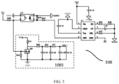
- the analytic circuit 108 in this embodiment is shown in FIG. 3 .
- the analytic circuit 108 includes a first chip U3, and the input signal of the second communication interface 105 is connected to a pin 5 of the first chip U3.
- the first chip U3 Upon the signal being a 0-10 volts signal, the first chip U3 outputs the corresponding duty cycle PWM signal at its pin 4 according to the 0-10 volts level.
- the pin 4 of the first chip U3 is connected to a terminal of an input side of a second optocoupler U2 through an eighth resistor R33, another terminal of the input side of the second optocoupler U2 is grounded, and a ninth resistor R58 is also connected between the terminal of the input side of the second optocoupler U2 and the another terminal of the input side of the second optocoupler U2.
- a terminal of an output side of the second optocoupler U2 is connected to a second conversion circuit 1081 and also pulled up at a high level of 3.3V through an eleventh resistor R30, another terminal of the output side of the second optocoupler U2 is grounded.
- the second conversion circuit 1081 converts a received PWM waveform into a level signal that can be processed by the processor 102, and the level signal is outputted by an output terminal ADC1.
- the second conversion circuit 1081 has the same structure and function as the first conversion circuit 1042.
- the second conversion circuit 1081 includes an MOS transistor Q4.
- a gate of the MOS transistor Q4 is connected to the terminal of the output side of the second optocoupler U2.
- a twelfth resistor R62 is connected between the gate of the MOS transistor Q4 and the ground.
- a source of the MOS transistor Q4 is grounded, and a drain of the MOS transistor Q4 is pulled up at a high level of 3.3V through a thirteenth resistor R59.
- a fourteenth resistor R60, a fifteenth resistor R61 and a sixteenth resistor R63 are connected in series in sequence between the drain of the MOS transistor Q4 and the output terminal ADC1 of the second conversion circuit 1081.
- a terminal of a second capacitor C55 is connected to a connection point of the fourteenth resistor R60 and the fifteenth resistor R61 and another terminal of the second capacitor C55 is grounded.
- a terminal of a third capacitor C18 isconnected to a connection point of the fifteenth resistor R61 and the sixteenth resistor R63 and another terminal of the third capacitor C18 is grounded.
- a fourth capacitor C19 and a fifth capacitor C20 are connected in parallel between the output terminal ADC1 of the second conversion circuit 1081 and the ground.
- the processor 102 in this embodiment is an MCU chip as shown in FIG. 4 .
- the PWM terminal of the detection circuit 104 is connected to a pin 32
- the output terminal ADC1 of the second conversion circuit 1081 is connected to a pin 16
- the output terminal ADC2 of the first conversion circuit 1042 is connected to a pin 14.
- the numbers of the pins may vary with the model of the MCU chip, which is not limited in the present application.
- the MCU determines that the input of the second communication interface 105 is a 0-10 volts signal, receives the signal which is transmitted from the output terminal ADC1 of the second conversion circuit 1081 to the pin 16, and converts the signal into a DALI signal.
- the MCU determines that the input of the second communication interface 105 is a PWM signal, receives the signal which is transmitted from the output terminal ADC2 of the first conversion circuit 1042 to the pin 14, and converts the signal into a DALI signal.
- the lighting system controller 1 Upon no signal being received by the second communication interface 105, the PWM terminal of the detection circuit 104 has no signal output, the lighting system controller 1, as an independent DALI controller, directly outputs the control signal to the first communication interface 106 and its subordinate lamps by the control module 103.
- the aforesaid lighting system controller 1 can be used in any form of wired lighting control system.
- the lighting system controller 1 is connected to a track 2, a sectional diagram of which is shown in FIG. 5 .
- the track 2 includes a track body 21 and a first conductive bar 22, a second conductive bar 24 and a third conductive bar 23 arranged along an extension direction of the track body 21.
- the first conductive bar 22 is configured to transmit a first control signal
- the second conductive bar 24 is configured to transmit a second control signal or a third control signal
- the third conductive bar 23 is configured for power supply.
- the lighting system controller 1 is disposed on the track body 21, the first communication interface 106 of the lighting system controller 1 is electrically connected to the first conductive bar 22, and the second communication interface 105 is electrically connected to the second conductive bar 24.
- the lighting system controller 1 is directly disposed on the track body 21.
- the lighting system controller 1 may also be disposed outside the track body 21, and wires are used to connect the first communication interface 106 and the first conductive bar 22 and connect the second communication interface 105 and the second conductive bar 24, which is not limited in the present application.
- the above track 2 and the lighting system controller 1 which have been connected, as well as at least one lighting unit 3 disposed on the track body 21 form a lighting system of a preferred embodiment of the present application, a structure block diagram of which is shown in FIG. 6 .
- the lighting unit 3 is disposed on the track body 21, the lighting unit 3 is electrically connected to the third conductive bar 23 to receive the power supply, and the lighting unit 3 is electrically connected to the first conductive bar 22 to receive the first control signal outputted by the first communication interface 106 and respond to the signal to be controlled for dimming and toning.
- the lighting system further includes a superior track 4.
- the superior track 4 includes a fourth conductive bar 42 for transmitting a second control signal or a third control signal and a fifth conductive bar 41 for power supply.
- the fourth conductive bar 42 is electrically connected to the second conductive bar 24, and the fifth conductive bar 41 is electrically connected to the third conductive bar 23.
- the first conductive bar 22 and the second conductive bar 24 transmit the first control signal and the second control signal or the third control signal respectively, and the lighting unit 3 only accepts the first control signal transmitted from the first conductive bar 22.
- the lighting system controller 1 converts the second control signal or the third control signal on the second conductive bar 24 into the first control signal, and then transmits the first control signal to the first conductive bar 22 to control the lighting unit 3.
- the first control signal is a DALI control signal
- the second control signal is a PWM control signal
- the third control signal is a 0-10 volts control signal.
- the superior track 4 may be a part of an existing track lighting system. In a case where there is a need for extension, it may be impossible to purchase a track with the same structure as the original superior track 4, or it may be impossible to purchase a lighting unit 3 that can be installed on the original superior track 4.
- the superior track 4 is a PWM control system, but most of lamps on the market are of DALI-controlled lamps at present, then by connecting to the track 2 in this embodiment, the new lighting unit 3 can be connected to the original track system.
- new DALI lamps can be installed on the track 2 provided in the present application, and can be compatible with two control modes of PWM and 0-10 volts after being connected to the superior track 4.
Landscapes
- Engineering & Computer Science (AREA)
- General Engineering & Computer Science (AREA)
- Power Engineering (AREA)
- Circuit Arrangement For Electric Light Sources In General (AREA)
Abstract
Description
- The present application claims the priority of the
Chinese Patent Application No. 202210555262.9 filed on May 20, 2022 Chinese Patent Application No. 202221220658.X filed on May 20, 2022 - The present application relates to a field of lighting technology, and in particular to a lighting system controller, a track and a lighting system.
- Digital lighting technology has features of being easy to control and maintain, etc. It meets people's needs for energy conservation and emission reduction as well as intelligent management, and has been widely valued in the fields of industrial lighting and commercial lighting. As a standard communication interface and protocol, a DALI has been widely used in the lighting engineering with the logarithmic dimming curve and the gradient adjustment effect conforming to the human visual effect and with a rich dimming instruction set. The DALI protocol is established based on the master-slave control mode, in which a master controller and a lighting apparatus are included and dimming control is performed on the lighting apparatus by the master controller.
- In most of track light products at present, a DALI controller uses a track wire as a DALI bus to dim and tone a lamp to achieve track combined adjusting. However, when the lighting system is reformed, it is necessary to dock some other existing control systems. For example, the original track system is under PWM control or 0-10 volts control, and the new track system and the old track system cannot be directly connected due to different control protocols and thus cannot be controlled in a unified way. Therefore, how to simply and efficiently expand the existing track lighting systems and realize unified control of the different track systems has become an urgent problem to be solved.
- The purpose of the application is to solve the problem that the tracks of different control protocols of the track lighting control systems cannot be jointly controlled.
- In order to achieve the above purpose, the technical scheme adopted by the application is to provide a lighting system controller, including: a power supply module, a processor, a control module, which is used for generating a first control signal or processing the first control signal, and a first communication interface, the first communication interface being connected to the control module and an external control bus, the controller further includes:
- a second communication interface, being used to receive a second control signal or a third control signal;
- a detection circuit, being connected to the second communication interface and the processor, the detection circuit outputs a determination signal to the processor according to a type of a signal received by the second communication interface; the processor performs subsequent processing according to the determination signal; if it is determined that the signal received by the second communication interface is the second control signal, then the detection circuit also converts the second control signal, and the processor receives a signal obtained after the detection circuit converting the second control signal, and then the processor converts the signal into a first control signal and transmits the first control signal to the control module; and
- an analytic circuit, being connected to the second communication interface and the processor, if it is determined that the signal received by the second communication interface is the third control signal, then the processor receives a signal obtained after the analytic circuit converting the third control signal, and then the processor converts the signal into a first control signal and transmits the first control signal to the control module;
- upon second communication interface being input with the second control signal or the third control signal, the control module transmits the first control signal transmitted from the processor to the first communication interface, or otherwise, a first control signal generated by the control module itself is transmitted to the first communication interface.
- Preferably, the second control signal is a PWM control signal, and the third control signal is a 0-10 volts control signal.
- Preferably, the detection circuit includes an isolation circuit and a first conversion circuit, the second communication interface is connected to the isolation circuit, an input signal of the second communication interface is outputted at a PWM terminal after being processed by the isolation circuit, the PWM terminal outputs the determination signal to the processor, the first conversion circuit is connected to the PWM terminal and converts a signal of the PWM terminal into a signal that can be processed by the processor, and the signal is outputted from an output terminal ADC2.
- Preferably, upon an output of the PWM terminal being a PWM waveform, it is determined that the input signal of the second communication interface is the second control signal, and upon the output of the PWM terminal being at a high level, it is determined that the input signal of the second communication interface is the third control signal.
- Preferably, the isolation circuit includes a first optocoupler, a terminal of an input side of the first optocoupler is pulled up at a supply voltage through a first resistor, and is grounded through a first voltage regulator diode, and another terminal of the input side of the first optocoupler is connected to a collector of a first triode through a second resistor, a base of the first triode is connected to the second communication interface through a third resistor, an emitter of the first triode is grounded, a terminal of an output side of the first optocoupler is connected to a base of a second triode, a fourth resistor is connected to a high level and the base of the second triode, a fifth resistor is connected to a high level and a collector of the second triode, a sixth resistor and a first capacitor are connected in parallel between the collector of the second triode and an emitter of the second triode, a seventh resistor is connected between the collector of the second triode and the PWM terminal, and another terminal of the output side of the first optocoupler and the emitter of the second triode are grounded.
- Preferably, the analytic circuit includes a first chip, the input signal of the second communication interface is inputted into the first chip and converted into a PWM signal, the first chip is connected to a terminal of an input side of a second optocoupler through an eighth resistor, another terminal of the input side of the second optocoupler is grounded, a ninth resistor is also connected between the terminal of the input side of the second optocoupler and the another terminal of the input side of the second optocoupler, a terminal of an output side of the second optocoupler is connected to a second conversion circuit and also pulled up at a high level through an eleventh resistor, another terminal of the output side of the second optocoupler is grounded, the second conversion circuit converts a received signal into a signal that can be processed by the processor, and the signal is outputted by an output terminal ADC1.
- Preferably, the first conversion circuit and the second conversion circuit have the same structure and each include an MOS transistors, a gate of the MOS transistor is connected to the PWM terminal or the terminal of the output side of the second optocoupler, a twelfth resistor is connected between the gate of the MOS transistor and the ground, a source of the MOS transistor is grounded, a drain of the MOS transistor is pulled up at a high level through a thirteenth resistor, also, a fourteenth resistor, a fifteenth resistor and a sixteenth resistor are connected in series in sequence between the drain of the MOS transistor and the output terminal ADC2 of the first conversion circuit or the output terminal ADC1 of the second conversion circuit, a terminal of a second capacitor is connected to a connection point of the fourteenth resistor and the fifteenth resistor and another terminal of the second capacitor is grounded, a terminal of a third capacitor is connected to a connection point of the fifteenth resistor and the sixteenth resistor and another terminal of the third capacitor is grounded, and a fourth capacitor and a fifth capacitor are connected in parallel between the ground and the output terminal ADC2 of the first conversion circuit or the output terminal ADC1 of the second conversion circuit.
- Preferably, the first control signal is a DALI signal.
- The present application also provides a track, the track includes a track body and a first conductive bar, a second conductive bar and a third conductive bar arranged along an extension direction of the track body, the first conductive bar is configured to transmit a first control signal, the second conductive bar is configured to transmit a second control signal and a third control signal, the third conductive bar is configured for power supply, the lighting system controller as mentioned above is connected to the track body, the first communication interface is electrically connected to the first conductive bar, and the second communication interface is electrically connected to the second conductive bar.
- Preferably, the second control signal is a PWM control signal, and the third control signal is a 0-10 volts control signal.
- Preferably, the first control signal is a DALI control signal.
- The present application also provides a lighting system, including the track as mentioned above, the lighting system controller as mentioned above and at least one lighting unit, the lighting system controller is connected to the track body, the first communication interface is electrically connected to the first conductive bar, the second communication interface is electrically connected to the second conductive bar, the lighting unit is disposed on the track body, the lighting unit is electrically connected to the third conductive bar to receive the power supply, and the lighting unit is electrically connected to the first conductive bar to receive a first control signal outputted by the first communication interface and respond to the first control signal.
- Preferably, the lighting system further includes a superior track, the superior track includes a fourth conductive bar for transmitting a second control signal or a third control signal, and the fourth conductive bar is electrically connected to the second conductive bar.
- Preferably, the second control signal is a PWM control signal, the third control signal is a 0-10 volts control signal, and the first control signal is a DALI control signal; upon the fourth conductive bar being applied with the second control signal or the third control signal, the lighting system controller converts the second control signal or the third control signal into the first control signal to control the lighting unit, or otherwise the lighting system controller directly generates the first control signal to control the lighting unit.
- The lighting system controller provided in the present application not only retains the functions of the original controller to directly control lamps such as dimming and color-tuning, but also has an additional input interface which enables the lighting system controller to be connected to an existing track lighting system. During connection, a control signal line of the existing system is connected to a second communication interface. Through identification of the input signal of the second communication interface, two control systems of PWM control and 0-10 volts control can be compatible at the same time, and the input signal is converted into a DALI control signal. Therefore, the DALI lamp which is newly connected to the system can also be used, and is controlled simultaneously with the lamp in the original system. If it is not connected to the upstream line, then the controller will control its own track. The lighting system controller provided in the present application can not only be connected to the existing track system to realize unified arrangement and operation of the tracks in the whole house, but can also be used as a controller separately, thereby meeting different needs of different customers.
- Hereinbelow, the technical solutions and other beneficial effects of the present application will be made obvious through the detailed description of the specific implementation of the present application in combination with the attached drawings.
-
FIG. 1 is a structure schematic diagram of a controller of a preferred embodiment of the present application; -
FIG. 2 is a circuit diagram of a detection circuit in a controller of a preferred embodiment of the present application; -
FIG. 3 is a circuit diagram of an analytic circuit in a controller of a preferred embodiment of the present application; -
FIG. 4 is a peripheral circuit diagram of a processor in a controller of a preferred embodiment of the present application; -
FIG. 5 is a sectional structure schematic diagram of a track of a preferred embodiment of the present application; and -
FIG. 6 is a structure block diagram of a lighting system of a preferred embodiment of the present application. - A lighting system controller, a track and a lighting system proposed in this application will be further described in detail in combination with the attached drawings and specific embodiments hereinbelow.
-
FIG. 1 shows alighting system controller 1 of a preferred embodiment of the present application, which includes apower supply module 101, aprocessor 102, acontrol module 103 and afirst communication interface 106. The above part is the same as an existing controller, where thepower supply module 101 supplies power to theprocessor 102 and thecontrol module 103, thecontrol module 103 can generate a first control signal or process the first control signal, and the first control signal is connected to an external control bus through thefirst communication interface 106 so as to control a controlled device. Lamp control generally complies with a certain protocol. Thelighting system controller 1 of the embodiment of the present application is applied to a track lighting system, so a wired protocol is adopted. In this embodiment, the first control signal is a DALI control signal, thecontrol module 103 is a DALI master, an outside of thefirst communication interface 106 is connected to a DALI bus, and thelighting system controller 1 controls DALI lamps connected to the bus. - When a user purchases the DALI lamps, because the existing lighting control system is of PWM control or 0-10 volts control, the DALI lamps cannot be integrated into the existing system to be controlled in a unified way. The above module realizes all the functions of the traditional DALI controller. The improvement of the present application is that the
lighting system controller 1 also includes asecond communication interface 105, adetection circuit 104 and ananalytic circuit 108. Thesecond communication interface 105 can receive a second control signal or a third control signal. That is, thelighting system controller 1 in the present application can be compatible with two different control signals at the same time, and upon thelighting system controller 1 being input with different signals, thedetection circuit 104 firstly determines what kind of signal is inputted. Thedetection circuit 104 is connected to thesecond communication interface 105 and theprocessor 102. Thedetection circuit 104 outputs the determination signal to theprocessor 102 according to a type of a signal received by thesecond communication interface 105, and theprocessor 102 analyzes the determination signal and then performs subsequent processing. If it is determined that the signal received by thesecond communication interface 105 is the second control signal, theprocessor 102 receives a signal obtained after thedetection circuit 104 converts the second control signal, and then converts the signal into a first control signal and transmits the first control signal to thecontrol module 103. If it is determined that the signal received by thesecond communication interface 105 is the second control signal is, theprocessor 102 receives a signal obtained after thedetection circuit 104 converting the second control signal, and then converts the signal into a first control signal and transmits the first control signal to thecontrol module 103. If it is determined that the signal received by thesecond communication interface 105 is the third control signal, then theprocessor 102 receives a signal obtained after theanalytic circuit 108 converting the third control signal, and then the processor converts the signal into a first control signal and transmits the first control signal to thecontrol module 103. Uponsecond communication interface 105 being input with the second control signal or the third control signal, thecontrol module 103 transmits the first control signal transmitted from theprocessor 102 to thefirst communication interface 106. Since thefirst communication interface 106 is connected to the DALI bus, the lamps are all those controlled according to the DALI protocol, and thelighting system controller 1 proposed in the present application realizes the control of other lamp control signals on the DALI lamps. In other preferred embodiments, it may also be converted to other wired protocols such as DMX, which is not limited in the present application. On the contrary, uponsecond communication interface 105 being input with no signal, thelighting system controller 1 is still used as an independent controller, and thefirst communication interface 106 outputs the first control signal generated by thecontrol module 103 so as to control connected lamps. - In this embodiment, the second control signal is a PWM control signal, and the third control signal is a 0-10 volts control signal. That is, the
lighting system controller 1 can also be compatible with these two control signals and convert them into DALI signals to control the DALI lamps. - The specific circuit diagram of the
detection circuit 104 in this embodiment is shown inFIG. 2 . Thedetection circuit 104 includes afirst isolation circuit 1041 and afirst conversion circuit 1042. Thesecond communication interface 105 is connected to theisolation circuit 1041, and the input signals labeled IN+ and IN- of thesecond communication interface 105 in the diagram are outputted at a PWM terminal after being processed by theisolation circuit 1041. The PWM terminal is connected to theprocessor 102 and outputs a determination signal to theprocessor 102. Thefirst conversion circuit 1042 is connected to the PWM terminal and converts a signal of the PWM terminal into a signal that can be processed by theprocessor 102, and the signal is outputted from an output terminal ADC2. - As shown in
FIG. 2 , theisolation circuit 1041 includes a first optocoupler U1. A terminal of an input side of the first optocoupler U1 is pulled up at a supply voltage VCC1 through a first resistor R302, and is grounded through a first voltage regulator diode D33, and another terminal of the input side of the first optocoupler U1 is connected to a collector of a first triode Q1 through a second resistor R309. A base of the first triode Q1 is connected to the input signals IN+ and IN- through a third resistor R303. An emitter of the first triode Q1 is grounded. The input signals IN+ and IN- are inputted by thesecond communication interface 105. A terminal of an output side of the first optocoupler U1 is connected to a base of a second triode Q2. A fourth resistor R305 is connected to a high level of 3.3V and the base of the second triode Q2. A fifth resistor R306 is connected to a high level of 3.3V and a collector of the second triode Q2. A sixth resistor R308 and a first capacitor C79 are connected in parallel between the collector of the second triode Q2 and an emitter of the second triode Q2. A seventh resistor R307 is connected between the collector of the second triode Q2 and the PWM terminal. Another terminal of the output side of the first optocoupler U1 and the emitter of the second triode Q2 are grounded. - In this embodiment, the high level is 3.3V on average. In other embodiments, the high level can be set according to the requirements of the chip. The PWM terminal is connected to the
processor 102, and theprocessor 102 determines whether it is a 0-10 volts signal or a PWM signal to confirm the input according to whether it is the high level or the PWM waveform transmitted from the PWM terminal. Uponsecond communication interface 105 being input with the third control signal, which is a 0-10 volts signal in this embodiment, the high level is outputted at the PWM terminal after isolation of the first optocoupler U1. Uponsecond communication interface 105 being input with the second control signal, which is a PWM signal in this embodiment, the PWM waveform is outputted at the PWM terminal, and thecontroller 102 determines the PWM signal according to the waveform. The PWM waveform of 3.3V outputted at the PWM terminal is converted by thefirst conversion circuit 1042 into a level waveform which can be accepted by theprocessor 102, and the level waveform is outputted from the output terminal ADC2. The level waveform is received by theprocessor 102 and then converted into a DALI signal. Then, a downstream DALI lamp is dimmed synchronously through thecontroller 103, thereby achieving the effect of converting PWM dimming to DALI dimming. - The
first conversion circuit 1042 includes an MOS transistor Q3. A gate of the MOS transistor Q3 is connected to the PWM terminal. A twelfth resistor R4 is connected between the gate of the MOS transistor Q3 and the ground. A source of the MOS transistor Q3 is grounded, and a drain of the MOS transistor Q3 is pulled up at the high level of 3.3V through a thirteenth resistor R59. Also, a fourteenth resistor R1, a fifteenth resistor R2 and a sixteenth resistor R3 are connected in series in sequence connected between the drain of the MOS transistor Q3 and the output terminal ADC2 of thefirst conversion circuit 1042. A terminal of a second capacitor C1 is connected to a connection point of the fourteenth resistor R1 and the fifteenth resistor R2 and another terminal of the second capacitor C1 is grounded. A terminal of a third capacitor C2 is connected to a connection point of the fifteenth resistor R2 and the sixteenth resistor R3 and another terminal of the third capacitor C2 is grounded. A fourth capacitor C3 and a fifth capacitor C4 are connected in parallel between the output terminal ADC2 of thefirst conversion circuit 1042 and the ground. - The
analytic circuit 108 in this embodiment is shown inFIG. 3 . Theanalytic circuit 108 includes a first chip U3, and the input signal of thesecond communication interface 105 is connected to a pin 5 of the first chip U3. Upon the signal being a 0-10 volts signal, the first chip U3 outputs the corresponding duty cycle PWM signal at itspin 4 according to the 0-10 volts level. Thepin 4 of the first chip U3 is connected to a terminal of an input side of a second optocoupler U2 through an eighth resistor R33, another terminal of the input side of the second optocoupler U2 is grounded, and a ninth resistor R58 is also connected between the terminal of the input side of the second optocoupler U2 and the another terminal of the input side of the second optocoupler U2. A terminal of an output side of the second optocoupler U2 is connected to asecond conversion circuit 1081 and also pulled up at a high level of 3.3V through an eleventh resistor R30, another terminal of the output side of the second optocoupler U2 is grounded. Thesecond conversion circuit 1081 converts a received PWM waveform into a level signal that can be processed by theprocessor 102, and the level signal is outputted by an output terminal ADC1. - In this embodiment, the
second conversion circuit 1081 has the same structure and function as thefirst conversion circuit 1042. Thesecond conversion circuit 1081 includes an MOS transistor Q4. A gate of the MOS transistor Q4 is connected to the terminal of the output side of the second optocoupler U2. A twelfth resistor R62 is connected between the gate of the MOS transistor Q4 and the ground. A source of the MOS transistor Q4 is grounded, and a drain of the MOS transistor Q4 is pulled up at a high level of 3.3V through a thirteenth resistor R59. Also, a fourteenth resistor R60, a fifteenth resistor R61 and a sixteenth resistor R63 are connected in series in sequence between the drain of the MOS transistor Q4 and the output terminal ADC1 of thesecond conversion circuit 1081. A terminal of a second capacitor C55 is connected to a connection point of the fourteenth resistor R60 and the fifteenth resistor R61 and another terminal of the second capacitor C55 is grounded. A terminal of a third capacitor C18 isconnected to a connection point of the fifteenth resistor R61 and the sixteenth resistor R63 and another terminal of the third capacitor C18 is grounded. A fourth capacitor C19 and a fifth capacitor C20 are connected in parallel between the output terminal ADC1 of thesecond conversion circuit 1081 and the ground. - The
processor 102 in this embodiment is an MCU chip as shown inFIG. 4 . The PWM terminal of thedetection circuit 104 is connected to a pin 32, the output terminal ADC1 of thesecond conversion circuit 1081 is connected to a pin 16, and the output terminal ADC2 of thefirst conversion circuit 1042 is connected to apin 14. In other preferred embodiments, the numbers of the pins may vary with the model of the MCU chip, which is not limited in the present application. Upon the PWM terminal of thedetection circuit 104 being transmitted with the high level, the MCU determines that the input of thesecond communication interface 105 is a 0-10 volts signal, receives the signal which is transmitted from the output terminal ADC1 of thesecond conversion circuit 1081 to the pin 16, and converts the signal into a DALI signal. Upon the PWM terminal of thedetection circuit 104 being transmitted with the PWM waveform, the MCU determines that the input of thesecond communication interface 105 is a PWM signal, receives the signal which is transmitted from the output terminal ADC2 of thefirst conversion circuit 1042 to thepin 14, and converts the signal into a DALI signal. Upon no signal being received by thesecond communication interface 105, the PWM terminal of thedetection circuit 104 has no signal output, thelighting system controller 1, as an independent DALI controller, directly outputs the control signal to thefirst communication interface 106 and its subordinate lamps by thecontrol module 103. - The aforesaid
lighting system controller 1 can be used in any form of wired lighting control system. In a preferred embodiment, thelighting system controller 1 is connected to atrack 2, a sectional diagram of which is shown inFIG. 5 . Thetrack 2 includes atrack body 21 and a firstconductive bar 22, a secondconductive bar 24 and a thirdconductive bar 23 arranged along an extension direction of thetrack body 21. The firstconductive bar 22 is configured to transmit a first control signal, the secondconductive bar 24 is configured to transmit a second control signal or a third control signal, and the thirdconductive bar 23 is configured for power supply. Thelighting system controller 1 is disposed on thetrack body 21, thefirst communication interface 106 of thelighting system controller 1 is electrically connected to the firstconductive bar 22, and thesecond communication interface 105 is electrically connected to the secondconductive bar 24. In this embodiment, thelighting system controller 1 is directly disposed on thetrack body 21. In other preferred embodiments, thelighting system controller 1 may also be disposed outside thetrack body 21, and wires are used to connect thefirst communication interface 106 and the firstconductive bar 22 and connect thesecond communication interface 105 and the secondconductive bar 24, which is not limited in the present application. - The
above track 2 and thelighting system controller 1 which have been connected, as well as at least onelighting unit 3 disposed on thetrack body 21 form a lighting system of a preferred embodiment of the present application, a structure block diagram of which is shown inFIG. 6 . Thelighting unit 3 is disposed on thetrack body 21, thelighting unit 3 is electrically connected to the thirdconductive bar 23 to receive the power supply, and thelighting unit 3 is electrically connected to the firstconductive bar 22 to receive the first control signal outputted by thefirst communication interface 106 and respond to the signal to be controlled for dimming and toning. - The lighting system further includes a
superior track 4. Thesuperior track 4 includes a fourthconductive bar 42 for transmitting a second control signal or a third control signal and a fifthconductive bar 41 for power supply. The fourthconductive bar 42 is electrically connected to the secondconductive bar 24, and the fifthconductive bar 41 is electrically connected to the thirdconductive bar 23. At this point, the firstconductive bar 22 and the secondconductive bar 24 transmit the first control signal and the second control signal or the third control signal respectively, and thelighting unit 3 only accepts the first control signal transmitted from the firstconductive bar 22. At this time, through transparent transmission, thelighting system controller 1 converts the second control signal or the third control signal on the secondconductive bar 24 into the first control signal, and then transmits the first control signal to the firstconductive bar 22 to control thelighting unit 3. In this embodiment, the first control signal is a DALI control signal, the second control signal is a PWM control signal, and the third control signal is a 0-10 volts control signal. - The
superior track 4 may be a part of an existing track lighting system. In a case where there is a need for extension, it may be impossible to purchase a track with the same structure as the originalsuperior track 4, or it may be impossible to purchase alighting unit 3 that can be installed on the originalsuperior track 4. For example, if thesuperior track 4 is a PWM control system, but most of lamps on the market are of DALI-controlled lamps at present, then by connecting to thetrack 2 in this embodiment, thenew lighting unit 3 can be connected to the original track system. In this embodiment, new DALI lamps can be installed on thetrack 2 provided in the present application, and can be compatible with two control modes of PWM and 0-10 volts after being connected to thesuperior track 4. No matter which of the two control modes the original system has, it can be converted into a DALI control signal through thelighting system controller 1, then the newly added DALI track lights are connected to the same master of the original system for unified dimming and toning, and new tracks are laid on the premise of not changing the original track system so as to achieve unified management. In a case where there is no need for the original track system to unifiedly control a new device, thetrack 2, thelighting system controller 1 and thelighting unit 3 in this embodiment can form a set of independently controlled lighting system, and thelighting system controller 1 can realize autonomous DALI control as the traditional track controller. - The above description of the preferred embodiments of the present application is for illustration and description, but is not intended to exhaust or limit the present application to the specific form disclosed. It is clear that, many modifications and changes may be made, and those modifications and changes may be obvious to those skilled in the art and should be included within the scope of the present application as defined by the attached claims.
Claims (14)
- A lighting system controller, comprising a power supply module, a processor, a control module, which is used for generating a first control signal or processing the first control signal, and a first communication interface, the first communication interface being connected to the control module and an external control bus, wherein the controller further comprises:a second communication interface, being used to receive a second control signal or a third control signal;a detection circuit, being connected to the second communication interface and the processor, wherein the detection circuit outputs a determination signal to the processor according to a type of a signal received by the second communication interface; the processor performs subsequent processing according to the determination signal; if it is determined that the signal received by the second communication interface is the second control signal, then the detection circuit also converts the second control signal, and the processor receives a signal obtained after the detection circuit converting the second control signal, and then the processor converts the signal into a first control signal and transmits the first control signal to the control module; andan analytic circuit, being connected to the second communication interface and the processor, wherein if it is determined that the signal received by the second communication interface is the third control signal, then the processor receives a signal obtained after the analytic circuit converting the third control signal, and then the processor converts the signal into a first control signal and transmits the first control signal to the control module;upon second communication interface being input with the second control signal or the third control signal, the control module transmits the first control signal transmitted from the processor to the first communication interface, or otherwise, a first control signal generated by the control module itself is transmitted to the first communication interface.
- The lighting system controller according to claim 1, wherein the second control signal is a PWM control signal, and the third control signal is a 0-10 volts control signal.
- The lighting system controller according to claim 2, wherein the detection circuit comprises an isolation circuit and a first conversion circuit, the second communication interface is connected to the isolation circuit, an input signal of the second communication interface is outputted at a PWM terminal after being processed by the isolation circuit, the PWM terminal outputs the determination signal to the processor, the first conversion circuit is connected to the PWM terminal and converts a signal of the PWM terminal into a signal that can be processed by the processor, and the signal is outputted from an output terminal ADC2.
- The lighting system controller according to claim 3, wherein upon an output of the PWM terminal being a PWM waveform, it is determined that the input signal of the second communication interface is the second control signal, and upon the output of the PWM terminal being at a high level, it is determined that the input signal of the second communication interface is the third control signal.
- The lighting system controller according to claim 4, wherein the isolation circuit comprises a first optocoupler, a terminal of an input side of the first optocoupler is pulled up at a supply voltage through a first resistor, and is grounded through a first voltage regulator diode, and another terminal of the input side of the first optocoupler is connected to a collector of a first triode through a second resistor, a base of the first triode is connected to the second communication interface through a third resistor, an emitter of the first triode is grounded, a terminal of an output side of the first optocoupler is connected to a base of a second triode, a fourth resistor is connected to a high level and the base of the second triode, a fifth resistor is connected to a high level and a collector of the second triode, a sixth resistor and a first capacitor are connected in parallel between the collector of the second triode and an emitter of the second triode, a seventh resistor is connected between the collector of the second triode and the PWM terminal, and another terminal of the output side of the first optocoupler and the emitter of the second triode are grounded.
- The lighting system controller according to claim 4, wherein the analytic circuit comprises a first chip, the input signal of the second communication interface is inputted into the first chip and converted into a PWM signal, the first chip is connected to a terminal of an input side of a second optocoupler through an eighth resistor, another terminal of the input side of the second optocoupler is grounded, a ninth resistor is also connected between the terminal of the input side of the second optocoupler and the another terminal of the input side of the second optocoupler, a terminal of an output side of the second optocoupler is connected to a second conversion circuit and also pulled up at a high level through an eleventh resistor, another terminal of the output side of the second optocoupler is grounded, the second conversion circuit converts a received signal into a signal that can be processed by the processor, and the signal is outputted by an output terminal ADC.
- The lighting system controller according to claim 6, wherein the first conversion circuit and the second conversion circuit have the same structure and each comprise an MOS transistors, a gate of the MOS transistor is connected to the PWM terminal or the terminal of the output side of the second optocoupler, a twelfth resistor is connected between the gate of the MOS transistor and the ground, a source of the MOS transistor is grounded, a drain of the MOS transistor is pulled up at a high level through a thirteenth resistor, also, a fourteenth resistor, a fifteenth resistor and a sixteenth resistor are connected in series in sequence between the drain of the MOS transistor and the output terminal ADC2 of the first conversion circuit or the output terminal ADC1 of the second conversion circuit, a terminal of a second capacitor is connected to a connection point of the fourteenth resistor and the fifteenth resistor and another terminal of the second capacitor is grounded, a terminal of a third capacitor is connected to a connection point of the fifteenth resistor and the sixteenth resistor and another terminal of the third capacitor is grounded, and a fourth capacitor and a fifth capacitor are connected in parallel between the ground and the output terminal ADC2 of the first conversion circuit or the output terminal ADC1 of the second conversion circuit.
- The lighting system controller according to any one of claims 1 to 7, wherein the first control signal is a DALI signal.
- A track, wherein the track comprises a track body and a first conductive bar, a second conductive bar and a third conductive bar arranged along an extension direction of the track body, the first conductive bar is configured to transmit a first control signal, the second conductive bar is configured to transmit a second control signal and a third control signal, the third conductive bar is configured for power supply, the lighting system controller according to any one of claims 1 to 8 is connected to the track body, the first communication interface is electrically connected to the first conductive bar, and the second communication interface is electrically connected to the second conductive bar.
- The track according to claim 9, wherein the second control signal is a PWM control signal, and the third control signal is a 0-10 volts control signal.
- The track according to claim 10, wherein the first control signal is a DALI control signal.
- A lighting system, comprising the track according to any one of claims 9 to 11, the lighting system controller according to any one of claims 1 to 8 and at least one lighting unit, wherein the lighting system controller is connected to the track body, the first communication interface is electrically connected to the first conductive bar, the second communication interface is electrically connected to the second conductive bar, the lighting unit is disposed on the track body, the lighting unit is electrically connected to the third conductive bar to receive the power supply, and the lighting unit is electrically connected to the first conductive bar to receive a first control signal outputted by the first communication interface and respond to the first control signal.
- The lighting system according to claim 12, wherein the lighting system further comprises a superior track, the superior track comprises a fourth conductive bar for transmitting a second control signal or a third control signal, and the fourth conductive bar is electrically connected to the second conductive bar.
- The lighting system according to claim 12, wherein the second control signal is a PWM control signal, the third control signal is a 0-10 volts control signal, and the first control signal is a DALI control signal; upon the fourth conductive bar being applied with the second control signal or the third control signal, the lighting system controller converts the second control signal or the third control signal into the first control signal to control the lighting unit, or otherwise the lighting system controller directly generates the first control signal to control the lighting unit.
Applications Claiming Priority (3)
| Application Number | Priority Date | Filing Date | Title |
|---|---|---|---|
| CN202221220658.XU CN219678739U (en) | 2022-05-20 | 2022-05-20 | Lighting system controller, track and lighting system |
| CN202210555262.9A CN115151001B (en) | 2022-05-20 | 2022-05-20 | Lighting system controller, track and lighting system |
| PCT/CN2023/094402 WO2023221957A1 (en) | 2022-05-20 | 2023-05-16 | Lighting system controller, track, and lighting system |
Publications (2)
| Publication Number | Publication Date |
|---|---|
| EP4529358A1 true EP4529358A1 (en) | 2025-03-26 |
| EP4529358A4 EP4529358A4 (en) | 2025-09-24 |
Family
ID=88834656
Family Applications (1)
| Application Number | Title | Priority Date | Filing Date |
|---|---|---|---|
| EP23806909.0A Pending EP4529358A4 (en) | 2022-05-20 | 2023-05-16 | LIGHTING SYSTEM CONTROL, TRACK AND LIGHTING SYSTEM |
Country Status (3)
| Country | Link |
|---|---|
| US (1) | US20250159782A1 (en) |
| EP (1) | EP4529358A4 (en) |
| WO (1) | WO2023221957A1 (en) |
Family Cites Families (7)
| Publication number | Priority date | Publication date | Assignee | Title |
|---|---|---|---|---|
| WO2016115642A1 (en) * | 2015-01-23 | 2016-07-28 | Led Roadway Lighting Ltd. | Dual 0-10v/dali streetlighting controller |
| GB201611511D0 (en) * | 2016-03-10 | 2016-08-17 | Gooee Ltd | Universal smart lighting gateway |
| CN106714424A (en) * | 2017-01-09 | 2017-05-24 | 杭州优特电源有限公司 | Multi-control output type DALI signal conversion device |
| EP3751964A1 (en) * | 2019-06-11 | 2020-12-16 | Viva Company | System for controlling a series of lighting fixtures |
| CN111586919A (en) * | 2020-07-07 | 2020-08-25 | 珠海雷特科技股份有限公司 | Dimming signal converter with multi-signal input |
| CN215773666U (en) * | 2021-07-23 | 2022-02-08 | 漳州立达信光电子科技有限公司 | Switching circuit, intelligent connector and lamp |
| CN115151001B (en) * | 2022-05-20 | 2025-08-15 | 欧普照明股份有限公司 | Lighting system controller, track and lighting system |
-
2023
- 2023-05-16 WO PCT/CN2023/094402 patent/WO2023221957A1/en not_active Ceased
- 2023-05-16 EP EP23806909.0A patent/EP4529358A4/en active Pending
-
2024
- 2024-11-20 US US18/953,419 patent/US20250159782A1/en active Pending
Also Published As
| Publication number | Publication date |
|---|---|
| EP4529358A4 (en) | 2025-09-24 |
| US20250159782A1 (en) | 2025-05-15 |
| WO2023221957A1 (en) | 2023-11-23 |
Similar Documents
| Publication | Publication Date | Title |
|---|---|---|
| US9578711B2 (en) | LED driver, lighting device and LED based lighting application | |
| CN107426879B (en) | A PWM-based voltage dimming LED control system | |
| CN201585178U (en) | Control device of LED lamp based on DMX512 protocol | |
| CN103079313A (en) | Multimode dimming and multipath independent constant-current driving circuit for LED (light emitting diode) illumination | |
| CN101977478A (en) | Digital dimming control method and system for two-wire fluorescent lamps | |
| CN211297065U (en) | PWM isolation dimming driving power circuit with NFC function | |
| US12490366B2 (en) | Dimming system based on power line carrier and dimming and color adjusting control method | |
| CN117676947A (en) | An LED light source and lamp compatible with both silicon-controlled dimming and intelligent dimming | |
| CN117202427A (en) | LED power supply dimming control system and control method based on single-wire communication | |
| CN219678739U (en) | Lighting system controller, track and lighting system | |
| CN115151001B (en) | Lighting system controller, track and lighting system | |
| CN106658817B (en) | A kind of dim signal processing system for LED drive power | |
| CN101383084B (en) | An Isolated Bus Power Supply Communication System | |
| US20250159782A1 (en) | Lighting system controller, track, and lighting system | |
| CN111586919A (en) | Dimming signal converter with multi-signal input | |
| CN212278509U (en) | PLC intelligent lighting control system | |
| US20180287665A1 (en) | Power line-based communication method and device | |
| CN108366467A (en) | Single firewire signal light adjusting circuit | |
| US10342106B1 (en) | Smart dimming system | |
| CN216626110U (en) | Dimming control circuit, dimmer, driving circuit and lighting device | |
| CN211457453U (en) | LED dimming circuit and lighting equipment | |
| CN206894634U (en) | Communication device configured on power line | |
| CN115151002A (en) | Lighting System Controllers, Tracks and Lighting Systems | |
| CN211702450U (en) | Interface multiplexing circuit and LED control device | |
| CN107454705A (en) | A kind of plant lamp intelligent power system and light-dimming method based on DALI agreements |
Legal Events
| Date | Code | Title | Description |
|---|---|---|---|
| STAA | Information on the status of an ep patent application or granted ep patent |
Free format text: STATUS: THE INTERNATIONAL PUBLICATION HAS BEEN MADE |
|
| PUAI | Public reference made under article 153(3) epc to a published international application that has entered the european phase |
Free format text: ORIGINAL CODE: 0009012 |
|
| STAA | Information on the status of an ep patent application or granted ep patent |
Free format text: STATUS: REQUEST FOR EXAMINATION WAS MADE |
|
| 17P | Request for examination filed |
Effective date: 20241218 |
|
| AK | Designated contracting states |
Kind code of ref document: A1 Designated state(s): AL AT BE BG CH CY CZ DE DK EE ES FI FR GB GR HR HU IE IS IT LI LT LU LV MC ME MK MT NL NO PL PT RO RS SE SI SK SM TR |
|
| DAV | Request for validation of the european patent (deleted) | ||
| DAX | Request for extension of the european patent (deleted) | ||
| A4 | Supplementary search report drawn up and despatched |
Effective date: 20250826 |
|
| RIC1 | Information provided on ipc code assigned before grant |
Ipc: H05B 47/14 20200101AFI20250820BHEP Ipc: H05B 47/18 20200101ALI20250820BHEP Ipc: F21S 8/00 20060101ALI20250820BHEP Ipc: F21V 21/35 20060101ALI20250820BHEP Ipc: F21V 23/00 20150101ALI20250820BHEP Ipc: F21V 23/04 20060101ALI20250820BHEP Ipc: F21V 23/06 20060101ALI20250820BHEP |