EP4529156A1 - Control of camera monitoring system - Google Patents
Control of camera monitoring system Download PDFInfo
- Publication number
- EP4529156A1 EP4529156A1 EP23199006.0A EP23199006A EP4529156A1 EP 4529156 A1 EP4529156 A1 EP 4529156A1 EP 23199006 A EP23199006 A EP 23199006A EP 4529156 A1 EP4529156 A1 EP 4529156A1
- Authority
- EP
- European Patent Office
- Prior art keywords
- image data
- surveillance
- image sensor
- power state
- surrounding area
- Prior art date
- Legal status (The legal status is an assumption and is not a legal conclusion. Google has not performed a legal analysis and makes no representation as to the accuracy of the status listed.)
- Pending
Links
Images



Classifications
-
- H—ELECTRICITY
- H04—ELECTRIC COMMUNICATION TECHNIQUE
- H04N—PICTORIAL COMMUNICATION, e.g. TELEVISION
- H04N7/00—Television systems
- H04N7/18—Closed-circuit television [CCTV] systems, i.e. systems in which the video signal is not broadcast
- H04N7/188—Capturing isolated or intermittent images triggered by the occurrence of a predetermined event, e.g. an object reaching a predetermined position
-
- G—PHYSICS
- G08—SIGNALLING
- G08B—SIGNALLING SYSTEMS, e.g. PERSONAL CALLING SYSTEMS; ORDER TELEGRAPHS; ALARM SYSTEMS
- G08B13/00—Burglar, theft or intruder alarms
- G08B13/18—Actuation by interference with heat, light, or radiation of shorter wavelength; Actuation by intruding sources of heat, light, or radiation of shorter wavelength
- G08B13/189—Actuation by interference with heat, light, or radiation of shorter wavelength; Actuation by intruding sources of heat, light, or radiation of shorter wavelength using passive radiation detection systems
- G08B13/194—Actuation by interference with heat, light, or radiation of shorter wavelength; Actuation by intruding sources of heat, light, or radiation of shorter wavelength using passive radiation detection systems using image scanning and comparing systems
- G08B13/196—Actuation by interference with heat, light, or radiation of shorter wavelength; Actuation by intruding sources of heat, light, or radiation of shorter wavelength using passive radiation detection systems using image scanning and comparing systems using television cameras
- G08B13/19639—Details of the system layout
- G08B13/19647—Systems specially adapted for intrusion detection in or around a vehicle
-
- H—ELECTRICITY
- H04—ELECTRIC COMMUNICATION TECHNIQUE
- H04N—PICTORIAL COMMUNICATION, e.g. TELEVISION
- H04N23/00—Cameras or camera modules comprising electronic image sensors; Control thereof
- H04N23/60—Control of cameras or camera modules
- H04N23/61—Control of cameras or camera modules based on recognised objects
- H04N23/611—Control of cameras or camera modules based on recognised objects where the recognised objects include parts of the human body
-
- H—ELECTRICITY
- H04—ELECTRIC COMMUNICATION TECHNIQUE
- H04N—PICTORIAL COMMUNICATION, e.g. TELEVISION
- H04N23/00—Cameras or camera modules comprising electronic image sensors; Control thereof
- H04N23/60—Control of cameras or camera modules
- H04N23/65—Control of camera operation in relation to power supply
- H04N23/651—Control of camera operation in relation to power supply for reducing power consumption by affecting camera operations, e.g. sleep mode, hibernation mode or power off of selective parts of the camera
-
- H—ELECTRICITY
- H04—ELECTRIC COMMUNICATION TECHNIQUE
- H04N—PICTORIAL COMMUNICATION, e.g. TELEVISION
- H04N7/00—Television systems
- H04N7/18—Closed-circuit television [CCTV] systems, i.e. systems in which the video signal is not broadcast
- H04N7/181—Closed-circuit television [CCTV] systems, i.e. systems in which the video signal is not broadcast for receiving images from a plurality of remote sources
-
- G—PHYSICS
- G08—SIGNALLING
- G08B—SIGNALLING SYSTEMS, e.g. PERSONAL CALLING SYSTEMS; ORDER TELEGRAPHS; ALARM SYSTEMS
- G08B21/00—Alarms responsive to a single specified undesired or abnormal condition and not otherwise provided for
- G08B21/02—Alarms for ensuring the safety of persons
- G08B21/0202—Child monitoring systems using a transmitter-receiver system carried by the parent and the child
- G08B21/023—Power management, e.g. system sleep and wake up provisions
Definitions
- the disclosure relates generally to control of surveillance systems.
- the disclosure relates to control of camera monitoring systems for surveillance of a vehicle.
- the disclosure can be applied to heavy-duty vehicles, such as trucks, buses, and construction equipment, among other vehicle types.
- heavy-duty vehicles such as trucks, buses, and construction equipment, among other vehicle types.
- the disclosure may be described with respect to a particular vehicle, the disclosure is not restricted to any particular vehicle.
- Surveillance systems for heavy-duty vehicles help ensure the well-being of drivers, passengers, and cargo. These systems are designed to monitor, record, and analyze activities both inside and outside the vehicle, providing real-time and valuable information and valuable insights to fleet managers and operators.
- a computer system comprising processing circuitry configured to control a surveillance system to operate at a power saving state for a predetermined sleep time of a first surveillance cycle and upon lapse of the predetermined sleep time, control the surveillance system to operate at a detection power state.
- the processing circuitry is further configured to, at the detection power state, control the surveillance system to obtain first image data of a surrounding area of a vehicle and at the detection power state, process the first image data to determine whether at least one predetermined target is in the surrounding area.
- the processing circuitry is further configured to upon determining that the predetermined target is not present in the surrounding area, control the surveillance system to operate at the power saving state for the predetermined sleep time of a second surveillance cycle following the first surveillance cycle.
- the first aspect of the disclosure may seek to reduce a risk that an electrical power system of a vehicle is depleted.
- a technical benefit may include reducing an average power consumption (e.g. current consumption) of a surveillance system while avoiding altering a degree of protection provided by the surveillance system.
- processing circuitry is further configured to, during the second surveillance cycle, upon lapse of the predetermined sleep time, control the surveillance system to operate at the detection power state and at the detection power state, control the surveillance system to obtain second image data of the surrounding area of the vehicle.
- the processing circuitry is further configured to, at the detection power state, process the second image data to determine whether at least one predetermined target is in the surrounding area, and upon determining that the predetermined target is not present in the surrounding area, control the surveillance system to operate at the power saving state for the predetermined sleep time of a third surveillance cycle following the second surveillance cycle.
- a technical benefit may include reducing an average power consumption of a surveillance system while avoiding altering a degree of protection provided by the surveillance system.
- the second image data to determine whether the at least one predetermined target is present in the surrounding area by processing the image data further comprises processing the image data by comparison of the second image data to the first image data.
- a technical benefit may include providing a low power and efficient function of determining if a predetermined target is present in the surrounding area. This further reduces an average power consumption of the surveillance system while avoiding altering a degree of protection provided by the surveillance system.
- the processing circuitry is further configured to, at the detection power state, upon determining that the second image data is substantially different from the first image data, further process the first image data by an item recognition circuitry to determine presence of the predetermined target in the surrounding area.
- a technical benefit may include providing a low power and efficient function of determining if a predetermined target is present in the surrounding area and not consume more power than required in determining if the predetermined target is present in the surrounding area. This further reduces an average power consumption of the surveillance system while avoiding altering a degree of protection provided by the surveillance system.
- the processing circuitry is further configured to, at the detection power state, obtain the first image data from the surveillance system, wherein the surveillance system comprises a plurality of image sensor systems.
- a technical benefit may include providing select first image data relevant to a current situation and/or based on historic data.
- the processing circuitry is further configured to: obtain image data from a first image sensor subset comprising at least one image sensor system of the plurality of image sensor systems at the first surveillance cycle, and obtain image data from a second image sensor subset comprising at least one image sensor system of the plurality of image sensor systems at the second surveillance cycle, wherein the first image sensor subset is different from the second image sensor subset.
- a technical benefit may include monitoring a more complete area surrounding the vehicle thereby allowing the average power consumption of the surveillance system to be decreased while avoiding altering a degree of protection provided by the surveillance system.
- the processing circuitry is further configured to upon a lapse of the predetermined sleep time of each surveillance cycle, control a subset of a plurality of image sensor systems of the surveillance system to operate at the detection power state, wherein each subset of the plurality of image sensor systems is cycled through in an order, the order being at least one of, a predetermined order, a variable order determined depending on targets detected, a random order.
- a technical benefit may include monitoring a more complete area surrounding the vehicle thereby allowing the average power consumption of the surveillance system to be decreased while avoiding altering a degree of protection provided by the surveillance system.
- the processing circuitry is further configured to: during the second surveillance cycle, upon lapse of the predetermined sleep time, control the surveillance system to operate at the detection power state; at the detection power state, control the surveillance system to obtain second image data of the surrounding area of the vehicle; at the detection power state, process the second image data to determine whether at least one predetermined target is in the surrounding area; upon determining that the predetermined target is not present in the surrounding area, control the surveillance system to operate at the power saving state for the predetermined sleep time of a third surveillance cycle following the second surveillance cycle; at the detection power state, upon determining that the predetermined target is present in the surrounding area, control the surveillance system to operate at a monitoring power state; at the detection power state, upon determining that the second image data is substantially different from the first image data, further process the first image data by an item recognition circuitry to determine presence of the predetermined target in the surrounding area; at the detection power state, obtain the first image data from the surveillance system, wherein the surveillance system comprises a plurality of image
- a vehicle comprising the computer system of the first aspect.
- the second aspect of the disclosure may seek to reduce a risk that an electrical power system of a vehicle is depleted.
- a technical benefit may include providing surveillance of the vehicle for extended periods of time with a reduced risk of depleting an electrical power system of the vehicle.
- the power saving state is entered responsive to the vehicle being parked.
- a technical benefit may include automatically providing surveillance and safety of vehicle and/or driver at parked situations with a reduced risk of depleting the electrical power system of the vehicle.
- the vehicle is a heavy-duty vehicle.
- a technical benefit may include protection of the generally expensive vehicles and any cargo hauled by the vehicle.
- a computer implemented method comprises, controlling, by processing circuitry of a computer system, surveillance system to operate at a power saving state for a predetermined sleep time of a first surveillance cycle.
- the computer implemented method further comprises, upon lapse of the predetermined sleep time, controlling, by the processing circuitry of the computer system, the surveillance system to operate at a detection power state and at the detection power state, controlling, by the processing circuitry of the computer system, the surveillance system to obtain first image data of a surrounding area of a vehicle.
- the computer implemented method comprises, at the detection power state, processing, by the processing circuitry of the computer system, the first image data to determine whether at least one predetermined target is in the surrounding area and upon determining that the predetermined target is not present in the surrounding area, controlling, by the processing circuitry of the computer system, the surveillance system to operate at the power saving state for the predetermined sleep time of a second surveillance cycle following the first surveillance cycle.
- the third aspect of the disclosure may seek to reduce a risk that an electrical power system of a vehicle is depleted.
- a technical benefit may include reducing an average power consumption of a surveillance system while avoiding altering a degree of protection provided by the surveillance system.
- a computer program product comprises program code for performing, when executed by the processing circuitry, the method of the third aspect.
- the fourth aspect of the disclosure may seek to reduce a risk that an electrical power system of a vehicle is depleted.
- a technical benefit may include reducing an average power consumption of a surveillance system while avoiding altering a degree of protection provided by the surveillance system.
- a non-transitory computer-readable storage medium comprises instructions, which when executed by the processing circuitry, cause the processing circuitry to perform the method of the third aspect.
- the fifth aspect of the disclosure may seek to reduce a risk that an electrical power system of a vehicle is depleted.
- a technical benefit may include reducing an average power consumption of a surveillance system while avoiding altering a degree of protection provided by the surveillance system.
- One purpose of surveillance systems for heavy-duty vehicles is to augment safety, security, and efficiency within the transportation sector.
- advanced technologies such as cameras, sensors, and connectivity solutions, these systems are intended to address various challenges faced by fleet operators, including accident prevention, driver monitoring, cargo protection, and/or compliance with industry regulations.
- Surveillance systems in vehicles generally comprise high-resolution cameras. These cameras are strategically installed in and around the vehicle to capture a comprehensive view of the surroundings, both within the cabin and the external environment. Some surveillance systems comprise cameras offering night vision capabilities, wide-angle lenses, and high frame rates to ensure clear and accurate footage. To complement the camera's vision, surveillance systems generally comprise various sensors. These may include proximity sensors, collision detection sensors, and tire pressure monitoring sensors, among others. These sensors provide data to the surveillance system, contributing to real-time alerts and facilitating data analysis. Surveillance systems help protect valuable cargo from theft, damage, and tampering during transportation. They act as a deterrent to potential thieves and assist in the investigation of any suspicious activities.
- the teachings of the present disclosure provide methods, systems, functions and devices that may reduce power consumption of surveillance systems.
- power consumption may be decreased.
- the selective activation may be described as punctual image monitoring and/or a periodic image monitoring.
- the image circuitry may capture one or more images, and if no suspicious person or object is detected in these images, the image circuitry may go to sleep for a predetermined time before it wakes up again and captures one or more additional imaged.
- the frame rate may be increased if a suspicious person or object is detected in the captured images.
- FIG. 1 is an exemplary schematic side view of a heavy-duty vehicle 10 (hereinafter referred to as vehicle 10 ).
- vehicle 10 comprises a tractor unit 10a which is arranged to tow a trailer unit 10b.
- other vehicles may be employed, e.g., trucks, buses, and construction equipment.
- the vehicle 10 comprises all vehicle units and associated functionality to operate as expected, such as a powertrain, chassis, and various control systems.
- the vehicle 10 comprises one or more propulsion sources 12.
- the propulsion source 12 may be any suitable propulsion source 12 exemplified by, but not limited to, one or more or a combination of an electrical motor, a combustion engine such as a diesel, gas or gasoline powered engine.
- the vehicle 10 further comprises an energy source 14 suitable for providing energy for the propulsion source 12.
- the vehicle 10 further comprises sensor circuitry 16 arranged to detect, measure, sense or otherwise obtain data relevant for operation of the vehicle 10.
- the sensor circuit 16 may comprise one or more of an accelerometer, a gyroscope, a wheel Speed Sensor, an ABS sensor, a throttle position sensor, a fuel level sensor, a temperature Sensor, a pressure sensor, a rain sensor, a light sensor, proximity sensor, a lane departure warning sensor, a blind spot detection sensor, a TPMS sensor etc.
- Operational data relevant for operation of the vehicle 10 may include, but is not limited to, one or more of a speed of the vehicle 10, a weight of the vehicle 10, an inclination of the vehicle 10, a status of the energy source 14 of the vehicle 10 (state of charge, fuel level etc.), a current speed limit of a current road travelled by the vehicle 10, etc.
- the vehicle 10 may further comprise communications circuitry 18 configured to receive and/or send communication.
- the communications circuitry 18 may be configured to enable the vehicle 10 to communicate with one or more external devices or systems such as a cloud server 40.
- the communication with the external devices or systems may be directly or via a communications interface such as a cellular communications interface 30, such as a radio base station.
- the cloud server 40 may be any suitable cloud server exemplified by, but not limited to, Amazon Web Services (AWS), Microsoft Azure, Google Cloud Platform (GCP), IBM Cloud, Oracle Cloud Infrastructure (OCI), DigitalOcean, Vultr, Linode, Facebook Cloud, Rackspace etc.
- the communications interface may be a wireless communications interface exemplified by, but not limited to, Wi-Fi, Bluetooth, Zigbee, Z-Wave, LoRa, Sigfox, 2G (GSM, CDMA), 3G (UMTS, CDMA2000), 4G (LTE), 5G (NR) etc.
- the communication circuitry 18 may, additionally or alternatively, be configured to enable the vehicle 10 to be operatively connected to a Global Navigation Satellite System (GNSS) 20 exemplified by, but not limited to, global positioning system (GPS), Globalnaya Navigatsionnaya Sputnikovaya Sistema (GLONASS), Galileo, BeiDou Navigation Satellite System, Navigation with Indian Constellation (NavIC) etc.
- GNSS Global Navigation Satellite System
- GPS Globalnaya Navigatsionnaya Sputnikovaya
- Galileo BeiDou Navigation Satellite System
- NavIC Navigation with Indian Constellation
- the vehicle 10 in FIG. 1 further comprises a surveillance system 200 and a computer system 100.
- the computer system 100 may be operatively connected to the surveillance system 200, the communications circuitry 18, the sensor circuitry 16, the energy source 14 and/or the propulsion source 12 of the vehicle 10.
- the computer system 100 comprises processing circuitry 110.
- the computer system 100 may comprise a storage device 120, advantageously a non-volatile storage device such as a hard disk drives (HDDs), solid-state drives (SSDs) etc.
- the storage device 120 is operatively connected to the computer system 100.
- the surveillance system 200 may comprise surveillance system processing circuitry 210, the surveillance system processing circuitry 210 may be part of the processing circuitry 110 of the computer system 100.
- the surveillance system 200 may comprise one or more image sensor systems 220.
- An image sensor system 220 comprises one or more image sensors configured to sense, detect, measure or otherwise obtain image data of an inside or outside of the vehicle 10.
- the image sensor system 220 may be referred to as a camera monitoring system.
- the image sensor system 220 may be configured to capture still image data (still images) or a series of images forming video image data (video images).
- Still images are static visual representations captured using cameras or other imaging devices. Still images capture a single moment in time and do not have any motion or movement.
- a still image is a single frame, a snapshot frozen in time, capturing a specific scene or subject at a particular instance.
- a still image represents a single perspective or viewpoint.
- Still image data may be provided in any suitable format, exemplified by, but not limited to JPEG, PNG, GIF, or RAW.
- a video image is a series of still images played in rapid succession, creating the illusion of motion. It is substantially a sequence of continuous frames captured over time, resulting in a moving visual representation.
- Video images consist of multiple frames played one after another at a high speed, typically at 15, 24, 30, or 60 frames per second (FPS) although higher and lower frame rates may very well be considered. This creates the perception of motion, allowing viewers to see events unfolding over time.
- Video image data may be provided in any suitable format, exemplified by, but not limited to MP4, AVI, MOV, or MKV.
- FIG. 2 a top view of an exemplary vehicle 10 is shown.
- the vehicle 10 comprises a surveillance system 200 configured to monitor a surrounding area 205 of the vehicle 10.
- the surveillance system 200 comprises a plurality of image sensor systems 220, i.e. a front view image sensor system 221, a rear view image sensor system 224, a right view image sensor system 222, a left view image sensor system 223 and a birds view image sensor system 225.
- the front view image sensor system 221 is configured to monitor an area in front of the vehicle 10, in FIG. 2 delimited by front view delimiters 221'.
- the rear view image sensor system 224 is configured to monitor an area behind the vehicle 10, in FIG. 2 delimited by rear view delimiters 224'.
- the right view image sensor system 222 is configured to monitor an area to the right of the vehicle 10 (curb view camera in countries with right hand traffic), in FIG. 2 delimited by right view delimiters 222'.
- the left view image sensor system 223 is configured to monitor an area to the left of the vehicle 10 (curb view camera in countries with left hand traffic), in FIG. 2 delimited by left view delimiters 223'.
- the birds view image sensor system 225 is configured to monitor an area around vehicle 10, in FIG. 2 delimited by a bird view delimiter 225'. It should me mentioned that the location and field of views of the image sensor systems 221, 222, 223, 224, 225 in FIG. 2 are exemplary. In some examples, one or more of the image sensor systems 221, 222, 223, 224, 225 are configured with a 360° field of vies provide by e.g. one or more fishbowl lenses.
- the image sensor systems 221, 222, 223, 224, 225 are all mounted on the vehicle 10. This is one example, in other examples, one, some or all image sensor systems 220 are remote from the vehicle 10. This may be the case when the vehicle 10, by the communication circuitry 18, is operatively connected to image sensor systems 220 in e.g. parking garages etc. Further to this, in some examples, the vehicle 10 may comprise further image sensor systems 220 monitoring additional or overlapping areas around the vehicle 10.
- Two or more image sensor systems 220 may very well monitor substantially the same area around the vehicle 10, such configurations may be provided when one image sensor system 220 is an image sensor system configured for IR wavelength (a thermal system) and another image sensor system is a an image sensor system 220 configured for wavelengths seen by a human eye.
- a vehicle 10 according to the present disclosure may comprise any number of image sensor systems 220 and any combination of the image sensor systems 221, 222, 223, 224, 225 exemplified in FIG. 2 .
- the surveillance system 200 is configured to detect suspicious activity.
- the suspicious activity may comprise a predetermined target 50 being present in the surrounding area 205 of the vehicle 10.
- the predetermined target 50 is exemplified by a burglar running away, but this is for illustrative purposes only.
- the predetermined target 50 may be any type of object or person in the surrounding area 205 of the vehicle 10.
- Predetermined targets 50 may be persons or vehicles present in the surrounding area 205 of the vehicle 10.
- the predetermined targets 50 may be defined by a movement speed or movement pattern of persons or vehicles present in the surrounding area 205 of the vehicle 10.
- a person approaching the vehicle 10 and stopping in the surrounding area 205 of the vehicle 10 may be considered a predetermined target 50, while a person walking at a steady pace towards the vehicle 10 passing the vehicle 10 may not be considered a predetermined target 50.
- More advanced classifications where a stance of a person may be considered in defining what constitutes a predetermined target 50.
- FIG. 3 a block diagram of an architecture of a surveillance system manager 300 is shown.
- the computer system 100 and/or the surveillance system processing circuitry 210 may be configured to provide the functions and features of the surveillance system manager 300.
- the surveillance system manager 300 comprises a wakeup controller 310.
- the wakeup controller 310 is configured to wake the surveillance system manager 300 from a low power state.
- the wakeup controller 310 may be configured to wake the surveillance system manager 300 upon lapse of a predetermined sleep time 312.
- the wakeup controller 310 may be configured as a watchdog timer configured to generate an interrupt or other data upon lapse of the predetermined sleep time 312.
- the predetermined sleep time 312 is a configurable sleep time controlled by the surveillance system manager 300.
- the predetermined sleep time 312 is a fixed sleep time of 30 s or less.
- the predetermined sleep time 312 is a fixed sleep time of 15 s or less.
- the predetermined sleep time 312 is a fixed sleep time of 5 s or less. In some examples, the predetermined sleep time 312 is a random sleep time below a maximum sleep time. The maximum sleep time may be 30 s or less. A minimum value accepted for the predetermined sleep time 312 may be determined by hardware constraints of the system 100, 200 implementing the wakeup controller 310 such as a system clock frequency etc.
- the surveillance system manager 300 further comprises a low frame rate image obtainer 320, image obtainer 320 for short.
- the low frame rate image obtainer 320 is configured to obtain low frame rate image data 323, image data 323 for short, from one or more image sensor systems 220 of the surveillance system 200.
- the low frame rate image data 323 may be zero frame rate image data, i.e. still images.
- the low frame rate image obtainer 320 may be configured to obtain low frame rate image data 323 from any image sensor system 220 of the surveillance system 200.
- each time the low frame rate image obtainer 320 is activated it may be configured to obtain low frame rate image data 323 from an image sensor systems 220 that is different from an image sensor systems 220 from which image data 323 was obtained at a previous activation of the low frame rate image obtainer 320.
- the image obtainer 320 may be configured to, temporarily or persistently, store historic low frame rate image data 323 as previous low frame rate image data 323b, or a second low frame rate image data 323b.
- Current, or latest image data 323 may sometimes be referred to as current low frame image data 323a or first low frame rate image data 323a.
- the previous low frame rate image data 323b is stored in the storage device 120.
- the low frame rate image data 323 may be configured to cycle through the image sensor systems 221, 222, 223, 224, 225 by activating different image sensor systems 221, 222, 223, 224, 225 each time the low frame rate image obtainer 320 is activated.
- the low frame rate image obtainer 320 may be configured to obtain low frame rate image data 323 from the front view image sensor system 221 at a first activation, and to obtain low frame rate image data 323 from the rear view image sensor system 224 at a second activation, and so on cycling through the image sensor systems 221, 222, 223, 224, 225.
- the low frame rate image obtainer 320 may be configured to obtain low frame rate image data 323 from a subset of the image sensor systems 221, 222, 223, 224, 225 each time the low frame rate image obtainer 320 is activated.
- a first subset may comprise the front view image sensor system 221 and the right side image sensor system 223.
- a second subset may comprise the rear view image sensor system 224 and the right side image sensor system 223.
- a third subset may comprise the left view image sensor system 224, the rear view image sensor system 224 and the front view image sensor system 221.
- a fourth subset may comprise the birds view image sensor system 225.
- the same image sensor systems 221, 222, 223, 224, 225 may form part of different subsets and each subset may comprise just one image sensor systems 221, 222, 223, 224, 225 or a plurality of image sensor systems 221, 222, 223, 224, 225.
- An order of how the image sensor systems 221, 222, 223, 224, 225 or the subsets of image sensor systems 221, 222, 223, 224, 225 are cycled through may be a predetermined order, a variable order determined depending on the low frame rate image data 323, or a random order.
- the low frame rate image obtainer 320 may be configured to store the low frame rate image data 323 on a storage device, e.g. the storage device 120 of the computer system 100.
- the surveillance system manager 300 further comprises an image processor 330.
- the image processor 330 is configured to process the low frame rate image data 323 obtained by the low framerate image obtainer 320 to determine presence of at least one predetermined target 50 in the low frame rate image data 323.
- the image processor 321 may comprise a difference detector 321 configured to compare the low frame rate image data 323a to the previous low frame rate image data 323b obtained from the same image sensor system 220. If there is a difference between the two sets of low frame rate image data 323, the image processor 330 may be configured to provide a target indicator 329 indicating that the predetermined target 50 is preset in the low frame rate image data 323. Determining if there is a difference between the current low frame rate image data 323a and the previous low frame rate image data 323b may be done in one or more different ways such as pixel-wise comparison, mean squared error (MSE), structural similarity index (SSI), histogram comparison etc.
- MSE mean squared error
- SSI structural similarity index
- Pixel-wise comparison involves directly comparing the pixel values of corresponding pixels in the two sets of low frame rate image data 323.
- An absolute or squared difference between the pixel values can be calculated to quantify the dissimilarity.
- MSE is a metric used to measure the average squared difference between the pixel values of two images where a lower MSE values indicate greater similarity between the two sets of low frame rate image data 323.
- SSI is a metric that takes into account not only pixel-wise differences but also the structural information of the two sets of low frame rate image data 323. SSI is designed to provide a more accurate assessment of perceived image quality.
- Histograms of pixel intensities may be computed for both sets of low frame rate image data 323, and their differences may be quantified using various metrics like histogram intersection, Bhattacharyya distance, or Earth Mover's Distance, etc. Detecting a difference between the two sets of low frame rate image data 323 is a simple, low power and fast way of determining presence of the predetermined target 50 in the low frame rate image data 323.
- the difference between the two sets of low frame rate image data 323 may have to be greater than a difference threshold 322 in order to provide a target indicator 329 indicating that the predetermined target 50 is preset in the low frame rate image data 323.
- the difference threshold 322 may be a percentage difference indicating a number of pixels being different between the two sets of low frame rate image data 323.
- the previous low frame rate image data 323b may be provided as an average of a plurality of sets of previous low frame rate image data 323b.
- the image processor 330 may comprise an item recognizer 324.
- the item recognizer 324 may be configured to recognize features in the low frame rate image data 323. Feature recognition may involve extracting distinctive features from the low frame rate image data 323, such as edges, corners or descriptors, and then matching. The feature recognition of the item recognizer 324 may be paired with the difference detector 321 such that a target indicator 329 indicating that the predetermined target 50 is preset in the low frame rate image data 323 is provided if new and/or changed features are present in the low frame rate image data 323.
- the item recognizer 324 may be configured to perform object recognition in the low frame rate image data 323.
- Object recognition may be performed in numerous ways and generally involves computer vision techniques and machine learning algorithms to identify and classify objects within the low frame rate image data 323.
- Object recognition may comprise preprocessing of the low frame rate image data 323 e.g. resizing, normalization, converting the low frame rate image data 323 etc.
- the reprocessed low frame rate image data 323 is subjected to feature extraction wherein meaningful features are extracted from the low frame rate image data 323 that may represent the objects present in it.
- Features may be simple, such as the above exemplified edges, corners, and descriptors or more complex, like deep learning-based features extracted from convolutional neural networks (CNNs).
- CNNs convolutional neural networks
- the extracted features may be represented in a format that is suitable for further analysis. This may involve flattening the features into a vector or using more advanced techniques like feature histograms etc.
- a labeled dataset is provided to train the item recognizer 324. This dataset comprises images along with corresponding class labels, which indicate the objects present in the images.
- a machine learning algorithm may be trained to learn patterns and relationships between the extracted features and the corresponding object labels.
- Common machine learning algorithms for object recognition comprise support vector machines (SVMs), random forests, and deep learning-based methods like CNNs.
- the item recognizer 324 may be configured to provide post-processing to improve the object recognition results.
- the post-processing may comprise non-maximum suppression to eliminate duplicate detections, and thresholding may be applied to filter out low-confidence predictions.
- the item recognizer 324 is generally computationally heavier than the difference detector 321. To this end, in some examples, the item recognizer 324 is only executed responsive to the difference detector 321 detecting a difference between the two sets of low frame rate image data 323.
- the surveillance system manager 300 may further comprises a high frame rate image obtainer 340, video obtainer 340 for short.
- the high frame rate image obtainer 340 is configured to obtain high frame rate image data 343, video data 343 for short, from one or more image sensor systems 220 of the surveillance system 200.
- the high frame rate image data 343 may have any frame rate being higher than the frame of the low frame rate image data 323.
- the frame rate of the high frame rate image data 343 may be 5-20 fps, such as 15 fps.
- the frame rate of the high frame rate image data 343 may be 20-40 fps, such as 30 fps. In order to capture fast moving objects and/or fine details, the frame rate of the high frame rate image data 343 may be 40-100 fps, such as 60 fps.
- the high frame rate image obtainer 340 may be configured to obtain high frame rate image data 343 from any or all image sensor system 220 of the surveillance system 200.
- the high frame rate image obtainer 340 may be configured to obtain high frame rate image data 343 correspondingly to how the low frame rate image obtainer 320 may be configured to obtain low frame rate image data 323 as exemplified above.
- the surveillance system 200 may be controlled to obtain low frame rate image data 323, i.e. image data 323, of the surrounding area 205 of the vehicle 10.
- the low frame rate image data 323 may be obtained by controlling one or more image sensor systems 210 to obtain the low frame rate image data 323 as exemplified in reference to FIG. 3 and the image obtainer 320. Any image sensor system 210 activated in order to obtain the low frame rate image data 323 may be deactivated immediately after the low frame rate image data 323 have been obtained. This reduces power consumption of the surveillance system 200 further.
- the surveillance system 200 is configured to obtain high frame rate image data 343 from at least one image sensor system 210.
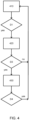
- the monitoring power state 430 may correspond to the functionality exemplified with reference to FIG. 3 and the video obtainer 440. If, at a fourth decision point D4, it is determined that there is no longer a need to remain at the monitoring power state 430, the surveillance system 200 is once more controlled to enter the power saving state 410 for the predetermined sleep time 312.
- the surveillance system 200 may be controlled to enter the power saving state 410 for the predetermined sleep time 312 responsive to an external reset such as an operator of vehicle 10 or surveillance personnel providing a reset for the surveillance system 200 in e.g.
- the surveillance system 200 may be controlled to enter the monitoring power state 430 responsive to reception of other triggers.
- Other triggers may be provided by sensor circuitry 16 such as PIR detectors etc.
- Other triggers may be provided via a user interface of the alarm system 200 where an operator of vehicle 10 may indicate distress.
- Other triggers may be provided via the communications circuitry 18 of the vehicle 10 where an remote operator of the vehicle 10 or the alarm system may indicate increased awareness.
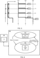
- FIG. 5 an exemplary state chart with associated current consumption i of a surveillance system 200 controlled according to the flowchart presented in FIG. 4 .
- the current consumption i is proportional to a power consumption of the surveillance system 200.
- the state chart and the current consumption i are shown along common time axis t.
- the surveillance system 200 enters a first surveillance cycle s1.
- the surveillance system 200 is controlled to operate at the power saving state 410 for the predetermined sleep time 312.
- the surveillance system 200 Upon lapse of the predetermined sleep time 312, the surveillance system 200 is controlled to enter the detection power state 420.
- first low frame rate image data 323 1 is obtained and presence of the predetermined target 50 in the surrounding area 205 is determined. Presence of the predetermined target 50 in the surrounding area 205 may be determined based on comparing the first low frame rate image data 323 1 to initial first low frame rate image data 323 0 . In FIG. 5 , it is, during the first surveillance cycle s1 , determined that the predetermined target 50 is not present in the surrounding area 205 and the surveillance system 200 is controlled to operate at the power saving state 410 for the predetermined sleep time 312 at a second surveillance cycle s2 following the first surveillance cycle s1 , this occurs at a second point in time T2.
- the surveillance system 200 is controlled to enter the detection power state 420.
- a second low frame rate image data 323 2 is obtained and presence of the predetermined target 50 in the surrounding area 205 is determined. Presence of the predetermined target 50 in the surrounding area 205 may be determined based on comparing the second low frame rate image data 323 2 to the first low frame rate image data 323 1 .
- the surveillance system 200 is controlled to operate at the power saving state 410 for the predetermined sleep time 312 at a third surveillance cycle s3 following the second surveillance cycle s2, this occurs at a third point in time T3.
- the surveillance system 200 is controlled to enter the detection power state 420.
- a third low frame rate image data 323 3 is obtained and presence of the predetermined target 50 in the surrounding area 205 is determined.
- Presence of the predetermined target 50 in the surrounding area 205 may be determined based on comparing the third low frame rate image data 323 3 to the first and/or the second low frame rate image data 323 1 , 323 2 . In FIG. 5 , it is, during the third surveillance cycle s3, determined that the predetermined target 50 is present in the surrounding area 205 and the surveillance system 200 is controlled to operate at the monitoring saving state 430.
- the current consumption i is significantly lower at the power saving state 410 compared to the detection power state 420 and the monitoring power state 430.
- the current consumption i shown in FIG. 5 is exemplary and it may be that configurations and specifications of the image sensor systems 220 is such that a peak current consumption, i.e. a peak power consumption, during the detection power state 420 may be substantially the same as a peak current consumption during the monitoring power state 430.
- average current consumptions, i.e. average power consumptions, of surveillance cycles s1 , s2 wherein the monitoring power state 430 is not entered is significantly lower than an average power consumption of the surveillance cycle s3 wherein the monitoring power state 430 is entered. Controlling the surveillance system 200 as presented by the present disclosure may significantly decrease an average power consumption of the surveillance system 200.
- FIG. 6 an exemplary block diagram of a surveillance system 200 controlled by the computer system 100 is shown.
- the computer system 100 comprises processing circuitry 110 configured to control the surveillance system 200 to operate at the power saving state 410 for the predetermined sleep time 312 of a first surveillance cycle s1.
- the processing circuitry 110 is configured to control the surveillance system 200 to operate at a detection power state 420.
- the processing circuitry 110 is configured to control the surveillance system 200 to obtain first image data 323 of a surrounding area 205 of a vehicle 10.
- the processing circuitry 110 is further configured to, at the detection power state 420, process the first image data 323 to determine whether at least one predetermined target 50 is in the surrounding area 205.
- the processing circuitry 110 Upon determining that the predetermined target 50 is not present in the surrounding area 205, the processing circuitry 110 is configured to control the surveillance system 200 to operate at the power saving state 410 for the predetermined sleep time 312 of a second surveillance cycle s2 following the first surveillance cycle s1.
- FIG. 7 an exemplary method 500 for controlling a surveillance system 200 is shown.
- the method 500 shown in FIG. 7 may be expanded and/or modified to comprise any suitable feature or function presented herein although not specifically mentioned in reference to FIG. 7 .
- the method 500 may comprise all or some of the actions, functions and features described with reference to FIG. 3 , FIG. 4 , FIG. 5 , and/or FIG. 6 .
- the method 500 may be a computer implemented method and may be performed by the processing circuitry 110 of the computer system 100 and/or the processing circuitry 210 of the surveillance system 200.
- the method 500 comprises controlling 510 the surveillance system 200 to operate at the power saving state 410 for the predetermined sleep time 312 of the first surveillance cycle s1.
- the method 500 further comprises, upon lapse of the predetermined sleep time 312, controlling 520 the surveillance system 200 to operate at the detection power state 420.
- the method 500 further comprises, at the detection power state 420, controlling 530 the surveillance system 200 to obtain first image data 323 of the surrounding area 205 of the vehicle 10.
- the method 500 further comprises, at the detection power state 420, processing 540 the first image data 323 to determine 550 whether at least one predetermined target 50 is in the surrounding area 205.
- the method 500 further comprises, upon determining 550 that the predetermined target 50 is not present in the surrounding area 205, controlling 560 the surveillance system 200 to operate at the power saving state 410 for the predetermined sleep time 312 of a second surveillance cycle s2 following the first surveillance cycle s1 .
- the computer program product 6 00 comprises a computer program 800 and a non-transitory computer readable medium 700.
- the computer program 800 may be stored on the computer readable medium 700.
- the computer readable medium 700 is, in FIG. 8 , exemplified as a vintage 5,25" floppy disc, but may be embodied as any suitable non-transitory computer readable medium such as, but not limited to, hard disk drives (HDDs), solid-state drives (SSDs), optical discs (e.g., CD-ROM, DVD-ROM, CD-RW, DVD-RW), USB flash drives, magnetic tapes, memory cards, Read-Only Memories (ROM), network-attached storage (NAS), cloud storage etc.
- HDDs hard disk drives
- SSDs solid-state drives
- optical discs e.g., CD-ROM, DVD-ROM, CD-RW, DVD-RW
- USB flash drives magnetic tapes
- memory cards Read-Only Memories (ROM), network-attached storage (NAS
- the computer program 800 comprises instruction 810 e.g. program instruction, software code, that, when executed by processing circuitry cause the processing circuitry to perform the method 500 introduced with reference to FIG. 7 .
- instruction 810 e.g. program instruction, software code
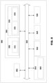
- FIG. 9 is a schematic diagram of a computer system 900 for implementing examples disclosed herein.
- the computer system 900 may be the computer system 100 introduced with reference to FIG. 1 .
- the computer system 900 is adapted to execute instructions from a computer-readable medium to perform these and/or any of the functions or processing described herein.
- the computer system 900 may be connected (e.g., networked) to other machines in a LAN, an intranet, an extranet, or the Internet. While only a single device is illustrated, the computer system 900 may include any collection of devices that individually or jointly execute a set (or multiple sets) of instructions to perform any one or more of the methodologies discussed herein.
- any reference in the disclosure and/or claims to a computer system, computing system, computer device, computing device, control system, control unit, electronic control unit (ECU), processor device, processing circuitry, etc. includes reference to one or more such devices to individually or jointly execute a set (or multiple sets) of instructions to perform any one or more of the methodologies discussed herein.
- control system may include a single control unit or a plurality of control units connected or otherwise communicatively coupled to each other, such that any performed function may be distributed between the control units as desired.
- such devices may communicate with each other or other devices by various system architectures, such as directly or via a Controller Area Network (CAN) bus, etc.
- CAN Controller Area Network
- the computer system 900 may comprise at least one computing device or electronic device capable of including firmware, hardware, and/or executing software instructions to implement the functionality described herein.
- the computer system 900 may include processing circuitry 902 (e.g., processing circuitry including one or more processor devices or control units), a memory 904, and a system bus 906.
- the processing circuitry 902 may comprise the processing circuitry 110 of the computer system 100 and/or the processing circuitry 210 of the surveillance system 200 introduced with reference to FIG. 1 .
- the computer system 900 may include at least one computing device having the processing circuitry 902.
- the system bus 906 provides an interface for system components including, but not limited to, the memory 904 and the processing circuitry 902.
- the processing circuitry 902 may include any number of hardware components for conducting data or signal processing or for executing computer code stored in memory 904.
- the processing circuitry 902 may, for example, include a general-purpose processor, an application specific processor, a Digital Signal Processor (DSP), an Application Specific Integrated Circuit (ASIC), a Field Programmable Gate Array (FPGA), a circuit containing processing components, a group of distributed processing components, a group of distributed computers configured for processing, or other programmable logic device, discrete gate or transistor logic, discrete hardware components, or any combination thereof designed to perform the functions described herein.
- the processing circuitry 902 may further include computer executable code that controls operation of the programmable device.
- the system bus 906 may be any of several types of bus structures that may further interconnect to a memory bus (with or without a memory controller), a peripheral bus, and/or a local bus using any of a variety of bus architectures.
- the memory 904 may be one or more devices for storing data and/or computer code for completing or facilitating methods described herein.
- the memory 904 may include database components, object code components, script components, or other types of information structure for supporting the various activities herein. Any distributed or local memory device may be utilized with the systems and methods of this description.
- the memory 904 may be communicably connected to the processing circuitry 902 (e.g., via a circuit or any other wired, wireless, or network connection) and may include computer code for executing one or more processes described herein.
- the memory 904 may include non-volatile memory 908 (e.g., read-only memory (ROM), erasable programmable read-only memory (EPROM), electrically erasable programmable read-only memory (EEPROM), etc.), and volatile memory 910 (e.g., random-access memory (RAM)), or any other medium which can be used to carry or store desired program code in the form of machine-executable instructions or data structures and which can be accessed by a computer or other machine with processing circuitry 902.
- a basic input/output system (BIOS) 912 may be stored in the non-volatile memory 908 and can include the basic routines that help to transfer information between elements within the computer system 900.
- BIOS basic input/output system
- the computer system 900 may further include or be coupled to a non-transitory computer-readable storage medium such as the storage device 914, which may comprise, for example, an internal or external hard disk drive (HDD) (e.g., enhanced integrated drive electronics (EIDE) or serial advanced technology attachment (SATA)), HDD (e.g., EIDE or SATA) for storage, flash memory, or the like.
- HDD enhanced integrated drive electronics
- SATA serial advanced technology attachment
- the storage device 914 and other drives associated with computer-readable media and computer-usable media may provide non-volatile storage of data, data structures, computer-executable instructions, and the like.
- Computer-code which is hard or soft coded may be provided in the form of one or more modules.
- the module(s) can be implemented as software and/or hard-coded in circuitry to implement the functionality described herein in whole or in part.
- the modules may be stored in the storage device 914 and/or in the volatile memory 910, which may include an operating system 916 and/or one or more program modules 918.
- All or a portion of the examples disclosed herein may be implemented as a computer program 920 stored on a transitory or non-transitory computer-usable or computer-readable storage medium (e.g., single medium or multiple media), such as the storage device 914, which includes complex programming instructions (e.g., complex computer-readable program code) to cause the processing circuitry 902 to carry out actions described herein.
- the computer-readable program code of the computer program 920 can comprise software instructions for implementing the functionality of the examples described herein when executed by the processing circuitry 902.
- the storage device 914 may be a computer program product (e.g., readable storage medium) storing the computer program 920 thereon, where at least a portion of a computer program 920 may be loadable (e.g., into a processor) for implementing the functionality of the examples described herein when executed by the processing circuitry 902.
- the processing circuitry 902 may serve as a controller or control system for the computer system 900 that is to implement the functionality described herein.
- the computer system 900 may include an input device interface 922 configured to receive input and selections to be communicated to the computer system 900 when executing instructions, such as from a keyboard, mouse, touch-sensitive surface, etc. Such input devices may be connected to the processing circuitry 902 through the input device interface 922 coupled to the system bus 906 but can be connected through other interfaces, such as a parallel port, an Institute of Electrical and Electronic Engineers (IEEE) 1394 serial port, a Universal Serial Bus (USB) port, an IR interface, and the like.
- the computer system 900 may include an output device interface 924 configured to forward output, such as to a display, a video display unit (e.g., a liquid crystal display (LCD) or a cathode ray tube (CRT)).
- the computer system 900 may include a communications interface 926 suitable for communicating with a network as appropriate or desired.
- Example 3 The computer system 100 of example 1 or 2, wherein the processing circuitry 110 is further configured to: at the detection power state 420, upon determining that the predetermined target 50 is present in the surrounding area 205, control the surveillance system 200 to operate at a monitoring power state 430.
- Example 4 The computer system 100 of example 2 or 3, wherein processing the second image data 323 2 to determine whether the at least one predetermined target 50 is present in the surrounding area 205 by processing the image data 323 further comprises processing the image data 323 by comparison of the second image data 323 2 to the first image data 323 1 .
- Example 5 The computer system 100 of example 4, wherein the processing circuitry 110 is further configured to, at the detection power state 420: upon determining that the second image data 323 2 is substantially different from the first image data 323 1 , further process the first image data 323 1 by an item recognition circuitry 324 to determine presence of the predetermined target 50 in the surrounding area 205.
- Example 6 The computer system 100 of any one of examples 1 to 5, wherein the processing circuitry 110 is further configured to, at the detection power state 420: obtain the first image data 323 1 from the surveillance system 200, wherein the surveillance system 200 comprises a plurality of image sensor systems 220.
- Example 7 The computer system 100 of example 6, wherein the plurality of image sensor systems 220 comprises two or more of a front view image sensor system 220, a rear view image sensor system 220, a right view image sensor system 220, a left view image sensor system 220 or a birds view image sensor system 220.
- Example 8 The computer system 100 of example 6 or 7, wherein the processing circuitry 110 is further configured to: obtain image data 323 from a first image sensor subset comprising at least one image sensor system 220 of the plurality of image sensor systems 220 at the first surveillance cycle s1 , and obtain image data 323 from a second image sensor subset comprising at least one image sensor system 220 of the plurality of image sensor systems 220 at the second surveillance cycle s2, wherein the first image sensor subset is different from the second image sensor subset.
- Example 9 The computer system 100 of any one of examples 6 to 8, wherein the processing circuitry 110 is further configured to: upon a lapse of the predetermined sleep time 312 of each surveillance cycle, control a subset of a plurality of image sensor systems 220 of the surveillance system 200 to operate at the detection power state, wherein each subset of the plurality of image sensor systems 220 is cycled through in an order, the order being at least one of, a predetermined order, a variable order determined depending on targets detected, a random order.
- Example 10 The computer system 100 of any one of examples 1 to 9, wherein the processing circuitry 110 is further configured to: at the detection power state 420, obtain first image data 323 1 as a single still image.
- Example 11 The computer system 100 of any one of examples 3 to 10, wherein the processing circuitry 110 is further configured to: at the monitoring power state 430, obtain monitoring image data 323 with a higher framerate than the first image data 323 1 .
- Example 12 The computer system 100 of any one of examples 1 to 11, wherein the predetermined sleep time 312 is 30 s or less.
- Example 13 The computer system 100 of any one of examples 1 to 12, wherein the processing circuitry 110 is further configured to: upon obtaining sensor data, from sensor circuitry 16 of the vehicle 10, indicating movement at the surrounding area 205 of a vehicle 10, wake up from the power saving state 410 to the detection power state 420.
- Example 14 The computer system 100 of any one of examples 1 to 13, wherein the predetermined target 50 is a person and/or a suspicious object.
- Example 15 The computer system 100 of any one of examples 1 to 14, wherein the detection power state 420 consumes more power than the power saving state 410 and the monitoring power state 430 consumes more power than the detection power state 420.
- Example 16 The computer system 100 of example 1, wherein the processing circuitry 110 is further configured to: during the second surveillance cycle s2: upon lapse of the predetermined sleep time 312, control the surveillance system 200 to operate at the detection power state 420; at the detection power state 420, control the surveillance system 200 to obtain second image data 323 2 of the surrounding area 205 of the vehicle 10; at the detection power state 420, process the second image data 323 2 to determine whether at least one predetermined target 50 is in the surrounding area 205; upon determining that the predetermined target 50 is not present in the surrounding area 205, control the surveillance system 200 to operate at the power saving state 410 for the predetermined sleep time of a third surveillance cycle s 3 following the second surveillance cycle s2; upon determining that the predetermined target 50 is present in the surrounding area 205, control the surveillance system 200 to operate at a monitoring power state 430; wherein processing the second image data 323 2 to determine whether the at least one predetermined target 50 is present in the surrounding area 205 by processing the image data 323 further comprises processing the image
- Example 17 A vehicle 10 comprising the computer system 100 of any one of examples 1 to 16.
- Example 18 The vehicle 10 of example 17, wherein the power saving state 410 is entered responsive to the vehicle 10 being parked.
- Example 19 The vehicle 10 of example 17 or 18, wherein the vehicle 10 is a heavy-duty vehicle.
- Example 20 A computer implemented method 500 comprising: controlling 510, by processing circuitry 110 of a computer system 100, surveillance system 200 to operate at a power saving state 410 for a predetermined sleep time 312 of a first surveillance cycle s1 ; upon lapse of the predetermined sleep time 312, controlling 520, by the processing circuitry 110 of the computer system 100, the surveillance system 200 to operate at a detection power state 420; at the detection power state 420, controlling 530, by the processing circuitry 110 of the computer system 100, the surveillance system 200 to obtain first image data 323 1 of a surrounding area 205 of a vehicle 10; at the detection power state 420, processing 540, by the processing circuitry 110 of the computer system 100, the first image data 323 1 to determine 550 whether at least one predetermined target 50 is in the surrounding area 205; upon determining 550 that the predetermined target 50 is not present in the surrounding area 205, controlling 560, by the processing circuitry 110 of the computer system 100, the surveillance system 200 to operate at the power saving state 410 for the pre
- Example 21 The computer implemented method 500 of example 20, further comprising: upon lapse of the predetermined sleep time 312, controlling, by the processing circuitry 110 of the computer system 100, the surveillance system 200 to operate at the detection power state 420; at the detection power state 420, controlling, by the processing circuitry 110 of the computer system 100, the surveillance system 200 to obtain second image data 323 2 of the surrounding area 205 of the vehicle 10; at the detection power state 420, processing, by the processing circuitry 110 of the computer system 100, the second image data 323 2 to determine whether at least one predetermined target 50 is in the surrounding area 205; upon determining that the predetermined target 50 is not present in the surrounding area 205, controlling, by the processing circuitry 110 of the computer system 100, the surveillance system 200 to operate at the power saving state 410 for the predetermined sleep time of a third surveillance cycle s 3 following the second surveillance cycle s2.
- Example 22 The computer implemented method 500 of example 20 or 21, further comprising: at the detection power state 420, upon determining that the predetermined target 50 is present in the surrounding area 205, controlling, by the processing circuitry 110 of the computer system 100, the surveillance system 200 to operate at a monitoring power state 430.
- Example 23 The computer implemented method 500 of example 21 or 22, wherein processing the second image data 323 2 to determine whether the at least one predetermined target 50 is present in the surrounding area 205 by processing, by the processing circuitry 110 of the computer system 100, the image data 323 further comprises processing the image data 323 by comparison of the second image data 323 2 to the first image data 323 1 .
- Example 24 The computer implemented method 500 of example 23, further comprising: upon determining that the second image data 323 2 is substantially different from the first image data 323 1 , further processing, by the processing circuitry 110 of the computer system 100, the first image data 323 1 by an item recognition circuitry 324 to determine presence of the predetermined target 50 in the surrounding area 205.
- Example 25 The computer implemented method 500 of any one of examples 20 to 24, further comprising: obtaining, by the processing circuitry 110 of the computer system 100, the first image data 323 1 from the surveillance system 200, wherein the surveillance system 200 comprises a plurality of image sensor systems 220.
- Example 26 The computer implemented method 500 of example 24 or 25, further comprising: obtaining, by the processing circuitry 110 of the computer system 100, image data 323 from a first image sensor subset comprising at least one image sensor system 220 of a plurality of image sensor systems 220 of the surveillance system 200 at the first surveillance cycle s1 , and obtaining, by the processing circuitry 110 of the computer system 100, image data 323 from a second image sensor subset comprising at least one image sensor system 220 of the plurality of image sensor systems 220 at the second surveillance cycle s2, wherein the first image sensor subset is different from the second image sensor subset.
- Example 27 The computer implemented method 500 of any one of examples 24 to 26, further comprising: upon a lapse of the predetermined sleep time 312 of each surveillance cycle, controlling, by the processing circuitry 110 of the computer system 100, a subset of a plurality of image sensor systems 220 of the surveillance system 200 to operate at the detection power state, wherein each subset of the plurality of image sensor systems 220 is cycled through in an order, the order being at least one of, a predetermined order, a variable order determined depending on targets detected, a random order.
- Example 28 The computer implemented method 500 of any one of examples 20 to 27, further comprising: at the detection power state 420, obtaining, by the processing circuitry 110 of the computer system 100, first image data 323 1 as a single still image.
- Example 29 The computer implemented method 500 of any one of examples 20 to 28, further comprising: at the monitoring power state 430, obtaining, by the processing circuitry 110 of the computer system 100, monitoring image data 323 with a higher framerate than the first image data 323 1 .
- Example 30 The computer implemented method 500 of any one of examples 20 to 29, further comprising: upon obtaining, by the processing circuitry 110 of the computer system 100, sensor data, from sensor circuitry 16 of the vehicle 10, indicating movement at the surrounding area 205 of a vehicle 10, waking up, by the processing circuitry 110 of the computer system 100, from the power saving state 410 to the detection power state 420.
- Example 31 A computer program product comprising program code for performing, when executed by the processing circuitry, the method of any of examples 20 to 30.
- Example 32 A non-transitory computer-readable storage medium comprising instructions, which when executed by the processing circuitry, cause the processing circuitry to perform the method of any of examples 20 to 30.
- Relative terms such as “below” or “above” or “upper” or “lower” or “horizontal” or “vertical” may be used herein to describe a relationship of one element to another element as illustrated in the Figures. It will be understood that these terms and those discussed above are intended to encompass different orientations of the device in addition to the orientation depicted in the Figures. It will be understood that when an element is referred to as being “connected” or “coupled” to another element, it can be directly connected or coupled to the other element, or intervening elements may be present. In contrast, when an element is referred to as being “directly connected” or “directly coupled” to another element, there are no intervening elements present.
Landscapes
- Engineering & Computer Science (AREA)
- Multimedia (AREA)
- Signal Processing (AREA)
- Physics & Mathematics (AREA)
- General Physics & Mathematics (AREA)
- Alarm Systems (AREA)
Abstract
A computer system (100) is presented. The computer system (100) comprises processing circuitry (110) configured to control a surveillance system (200) to operate at a power saving state (410) for a predetermined sleep time (312) of a first surveillance cycle. The processing circuitry (110) is further configured to, upon lapse of the predetermined sleep time (312), control the surveillance system (200) to operate at a detection power state (420) and at the detection power state (420), control the surveillance system (200) to obtain first image data (3231) of a surrounding area (205) of a vehicle (10). The processing circuitry (110) is further configured to, at the detection power state (420), process the first image data (3231) to determine whether at least one predetermined target (50) is in the surrounding area (205) and upon determining that the predetermined target (50) is not present in the surrounding area (205), control the surveillance system (200) to operate at the power saving state (410) for the predetermined sleep time of a second surveillance cycle following the first surveillance cycle.
Description
- The disclosure relates generally to control of surveillance systems. In particular aspects, the disclosure relates to control of camera monitoring systems for surveillance of a vehicle. The disclosure can be applied to heavy-duty vehicles, such as trucks, buses, and construction equipment, among other vehicle types. Although the disclosure may be described with respect to a particular vehicle, the disclosure is not restricted to any particular vehicle.
- Significant advancements are being made to enhance vehicle safety and security. Surveillance systems for heavy-duty vehicles help ensure the well-being of drivers, passengers, and cargo. These systems are designed to monitor, record, and analyze activities both inside and outside the vehicle, providing real-time and valuable information and valuable insights to fleet managers and operators.
- According to a first aspect of the disclosure, a computer system is presented. The computer system comprises processing circuitry configured to control a surveillance system to operate at a power saving state for a predetermined sleep time of a first surveillance cycle and upon lapse of the predetermined sleep time, control the surveillance system to operate at a detection power state. The processing circuitry is further configured to, at the detection power state, control the surveillance system to obtain first image data of a surrounding area of a vehicle and at the detection power state, process the first image data to determine whether at least one predetermined target is in the surrounding area. The processing circuitry is further configured to upon determining that the predetermined target is not present in the surrounding area, control the surveillance system to operate at the power saving state for the predetermined sleep time of a second surveillance cycle following the first surveillance cycle. The first aspect of the disclosure may seek to reduce a risk that an electrical power system of a vehicle is depleted. A technical benefit may include reducing an average power consumption (e.g. current consumption) of a surveillance system while avoiding altering a degree of protection provided by the surveillance system.
- Optionally in some examples, including in at least one preferred example, processing circuitry is further configured to, during the second surveillance cycle, upon lapse of the predetermined sleep time, control the surveillance system to operate at the detection power state and at the detection power state, control the surveillance system to obtain second image data of the surrounding area of the vehicle. The processing circuitry is further configured to, at the detection power state, process the second image data to determine whether at least one predetermined target is in the surrounding area, and upon determining that the predetermined target is not present in the surrounding area, control the surveillance system to operate at the power saving state for the predetermined sleep time of a third surveillance cycle following the second surveillance cycle. A technical benefit may include reducing an average power consumption of a surveillance system while avoiding altering a degree of protection provided by the surveillance system.
- Optionally in some examples, including in at least one preferred example, the processing circuitry is further configured to, at the detection power state, upon determining that the predetermined target is present in the surrounding area, control the surveillance system to operate at a monitoring power state. A technical benefit may include allowing the surveillance system to consume more power when a predetermined target is present in the surrounding area which reduces a risk that the degree of protection provided by the surveillance system is reduced.
- Optionally in some examples, including in at least one preferred example, the second image data to determine whether the at least one predetermined target is present in the surrounding area by processing the image data further comprises processing the image data by comparison of the second image data to the first image data. A technical benefit may include providing a low power and efficient function of determining if a predetermined target is present in the surrounding area. This further reduces an average power consumption of the surveillance system while avoiding altering a degree of protection provided by the surveillance system.
- Optionally in some examples, including in at least one preferred example, the processing circuitry is further configured to, at the detection power state, upon determining that the second image data is substantially different from the first image data, further process the first image data by an item recognition circuitry to determine presence of the predetermined target in the surrounding area. A technical benefit may include providing a low power and efficient function of determining if a predetermined target is present in the surrounding area and not consume more power than required in determining if the predetermined target is present in the surrounding area. This further reduces an average power consumption of the surveillance system while avoiding altering a degree of protection provided by the surveillance system.
- Optionally in some examples, including in at least one preferred example, the processing circuitry is further configured to, at the detection power state, obtain the first image data from the surveillance system, wherein the surveillance system comprises a plurality of image sensor systems. A technical benefit may include providing select first image data relevant to a current situation and/or based on historic data.
- Optionally in some examples, including in at least one preferred example, the processing circuitry is further configured to: obtain image data from a first image sensor subset comprising at least one image sensor system of the plurality of image sensor systems at the first surveillance cycle, and obtain image data from a second image sensor subset comprising at least one image sensor system of the plurality of image sensor systems at the second surveillance cycle, wherein the first image sensor subset is different from the second image sensor subset. A technical benefit may include monitoring a more complete area surrounding the vehicle thereby allowing the average power consumption of the surveillance system to be decreased while avoiding altering a degree of protection provided by the surveillance system.
- Optionally in some examples, including in at least one preferred example, the processing circuitry is further configured to upon a lapse of the predetermined sleep time of each surveillance cycle, control a subset of a plurality of image sensor systems of the surveillance system to operate at the detection power state, wherein each subset of the plurality of image sensor systems is cycled through in an order, the order being at least one of, a predetermined order, a variable order determined depending on targets detected, a random order. A technical benefit may include monitoring a more complete area surrounding the vehicle thereby allowing the average power consumption of the surveillance system to be decreased while avoiding altering a degree of protection provided by the surveillance system.
- Optionally in some examples, including in at least one preferred example, the processing circuitry is further configured to: during the second surveillance cycle, upon lapse of the predetermined sleep time, control the surveillance system to operate at the detection power state; at the detection power state, control the surveillance system to obtain second image data of the surrounding area of the vehicle; at the detection power state, process the second image data to determine whether at least one predetermined target is in the surrounding area; upon determining that the predetermined target is not present in the surrounding area, control the surveillance system to operate at the power saving state for the predetermined sleep time of a third surveillance cycle following the second surveillance cycle; at the detection power state, upon determining that the predetermined target is present in the surrounding area, control the surveillance system to operate at a monitoring power state; at the detection power state, upon determining that the second image data is substantially different from the first image data, further process the first image data by an item recognition circuitry to determine presence of the predetermined target in the surrounding area; at the detection power state, obtain the first image data from the surveillance system, wherein the surveillance system comprises a plurality of image sensor systems; obtain image data from a first image sensor subset comprising at least one image sensor system of the plurality of image sensor systems at the first surveillance cycle, and obtain image data from a second image sensor subset comprising at least one image sensor system of the plurality of image sensor systems at the second surveillance cycle, wherein the first image sensor subset is different from the second image sensor subset; and upon a lapse of the predetermined sleep time of each surveillance cycle, control a subset of a plurality of image sensor systems of the surveillance system to operate at the detection power state, wherein each subset of the plurality of image sensor systems is cycled through in an order, the order being at least one of, a predetermined order, a variable order determined depending on targets detected, a random order, wherein processing the second image data to determine whether the at least one predetermined target is present in the surrounding area by processing the image data further comprises processing the image data by comparison of the second image data to the first image data. A technical benefit may include any of the benefits mention in reference to the previous examples.
- According to a second aspect of the disclosure, a vehicle comprising the computer system of the first aspect is presented. The second aspect of the disclosure may seek to reduce a risk that an electrical power system of a vehicle is depleted. A technical benefit may include providing surveillance of the vehicle for extended periods of time with a reduced risk of depleting an electrical power system of the vehicle.
- Optionally in some examples, including in at least one preferred example, the power saving state is entered responsive to the vehicle being parked. A technical benefit may include automatically providing surveillance and safety of vehicle and/or driver at parked situations with a reduced risk of depleting the electrical power system of the vehicle.
- Optionally in some examples, including in at least one preferred example, the vehicle is a heavy-duty vehicle. A technical benefit may include protection of the generally expensive vehicles and any cargo hauled by the vehicle.
- According to a third aspect of the disclosure, a computer implemented method is presented. The computer implemented method comprises, controlling, by processing circuitry of a computer system, surveillance system to operate at a power saving state for a predetermined sleep time of a first surveillance cycle. The computer implemented method further comprises, upon lapse of the predetermined sleep time, controlling, by the processing circuitry of the computer system, the surveillance system to operate at a detection power state and at the detection power state, controlling, by the processing circuitry of the computer system, the surveillance system to obtain first image data of a surrounding area of a vehicle. computer implemented method comprises, at the detection power state, processing, by the processing circuitry of the computer system, the first image data to determine whether at least one predetermined target is in the surrounding area and upon determining that the predetermined target is not present in the surrounding area, controlling, by the processing circuitry of the computer system, the surveillance system to operate at the power saving state for the predetermined sleep time of a second surveillance cycle following the first surveillance cycle. The third aspect of the disclosure may seek to reduce a risk that an electrical power system of a vehicle is depleted. A technical benefit may include reducing an average power consumption of a surveillance system while avoiding altering a degree of protection provided by the surveillance system.
- According to a fourth aspect of the disclosure, a computer program product is presented. The computer program product comprises program code for performing, when executed by the processing circuitry, the method of the third aspect. The fourth aspect of the disclosure may seek to reduce a risk that an electrical power system of a vehicle is depleted. A technical benefit may include reducing an average power consumption of a surveillance system while avoiding altering a degree of protection provided by the surveillance system.
- According to a fifth aspect of the disclosure, a non-transitory computer-readable storage medium is presented. The non-transitory computer-readable storage medium comprises instructions, which when executed by the processing circuitry, cause the processing circuitry to perform the method of the third aspect. The fifth aspect of the disclosure may seek to reduce a risk that an electrical power system of a vehicle is depleted. A technical benefit may include reducing an average power consumption of a surveillance system while avoiding altering a degree of protection provided by the surveillance system.
- The disclosed aspects, examples (including any preferred examples), and/or accompanying claims may be suitably combined with each other as would be apparent to anyone of ordinary skill in the art. Additional features and advantages are disclosed in the following description, claims, and drawings, and in part will be readily apparent therefrom to those skilled in the art or recognized by practicing the disclosure as described herein.
- There are also disclosed herein computer systems, control units, code modules, computer-implemented methods, computer readable media, and computer program products associated with the above discussed technical benefits.
- Examples are described in more detail below with reference to the appended drawings.
-
FIG. 1 is an exemplary network diagram of a vehicle and surveillance according to an example. -
FIG. 2 is an exemplary top view of a vehicle and surveillance system according to an example. -
FIG. 3 is a schematic view of a surveillance system manager according to an example. -
FIG. 4 is a flow chart for controlling a surveillance system according to an example. -
FIG. 5 is a state change diagram of a surveillance system according to an example. -
FIG. 6 is a schematic view of a computer system controlling a surveillance system according to an example. -
FIG. 7 is a block diagram of a method for controlling a surveillance system according to an example. -
FIG. 8 is a schematic view of a computer program product according to an example. -
FIG. 9 is a schematic diagram of an exemplary computer system for implementing examples disclosed herein, according to an example. - The detailed description set forth below provides information and examples of the disclosed technology with sufficient detail to enable those skilled in the art to practice the disclosure.
- One purpose of surveillance systems for heavy-duty vehicles is to augment safety, security, and efficiency within the transportation sector. By utilizing advanced technologies such as cameras, sensors, and connectivity solutions, these systems are intended to address various challenges faced by fleet operators, including accident prevention, driver monitoring, cargo protection, and/or compliance with industry regulations.
- Surveillance systems in vehicles generally comprise high-resolution cameras. These cameras are strategically installed in and around the vehicle to capture a comprehensive view of the surroundings, both within the cabin and the external environment. Some surveillance systems comprise cameras offering night vision capabilities, wide-angle lenses, and high frame rates to ensure clear and accurate footage. To complement the camera's vision, surveillance systems generally comprise various sensors. These may include proximity sensors, collision detection sensors, and tire pressure monitoring sensors, among others. These sensors provide data to the surveillance system, contributing to real-time alerts and facilitating data analysis. Surveillance systems help protect valuable cargo from theft, damage, and tampering during transportation. They act as a deterrent to potential thieves and assist in the investigation of any suspicious activities.
- However, generally, the more advanced the surveillance system, the higher the power consumption of the surveillance system. This may become an issue for parked vehicles when surveillance systems may have to be powered from an on-board battery of the vehicle.
- The teachings of the present disclosure provide methods, systems, functions and devices that may reduce power consumption of surveillance systems. By providing a selective activation of an image circuitry of a surveillance system, power consumption may be decreased. The selective activation may be described as punctual image monitoring and/or a periodic image monitoring. The image circuitry may capture one or more images, and if no suspicious person or object is detected in these images, the image circuitry may go to sleep for a predetermined time before it wakes up again and captures one or more additional imaged. The frame rate may be increased if a suspicious person or object is detected in the captured images.
-
FIG. 1 is an exemplary schematic side view of a heavy-duty vehicle 10 (hereinafter referred to as vehicle 10). Thevehicle 10 comprises atractor unit 10a which is arranged to tow atrailer unit 10b. In other examples, other vehicles may be employed, e.g., trucks, buses, and construction equipment. Thevehicle 10 comprises all vehicle units and associated functionality to operate as expected, such as a powertrain, chassis, and various control systems. Thevehicle 10 comprises one ormore propulsion sources 12. Thepropulsion source 12 may be anysuitable propulsion source 12 exemplified by, but not limited to, one or more or a combination of an electrical motor, a combustion engine such as a diesel, gas or gasoline powered engine. Thevehicle 10 further comprises anenergy source 14 suitable for providing energy for thepropulsion source 12. That is to say, if thepropulsion source 12 is an electrical motor, asuitable energy source 14 would be a battery or a fuel cell. Thevehicle 10 further comprisessensor circuitry 16 arranged to detect, measure, sense or otherwise obtain data relevant for operation of thevehicle 10. Thesensor circuit 16 may comprise one or more of an accelerometer, a gyroscope, a wheel Speed Sensor, an ABS sensor, a throttle position sensor, a fuel level sensor, a temperature Sensor, a pressure sensor, a rain sensor, a light sensor, proximity sensor, a lane departure warning sensor, a blind spot detection sensor, a TPMS sensor etc. Operational data relevant for operation of thevehicle 10 may include, but is not limited to, one or more of a speed of thevehicle 10, a weight of thevehicle 10, an inclination of thevehicle 10, a status of theenergy source 14 of the vehicle 10 (state of charge, fuel level etc.), a current speed limit of a current road travelled by thevehicle 10, etc. Thevehicle 10 may further comprisecommunications circuitry 18 configured to receive and/or send communication. Thecommunications circuitry 18 may be configured to enable thevehicle 10 to communicate with one or more external devices or systems such as acloud server 40. The communication with the external devices or systems may be directly or via a communications interface such as acellular communications interface 30, such as a radio base station. Thecloud server 40 may be any suitable cloud server exemplified by, but not limited to, Amazon Web Services (AWS), Microsoft Azure, Google Cloud Platform (GCP), IBM Cloud, Oracle Cloud Infrastructure (OCI), DigitalOcean, Vultr, Linode, Alibaba Cloud, Rackspace etc. The communications interface may be a wireless communications interface exemplified by, but not limited to, Wi-Fi, Bluetooth, Zigbee, Z-Wave, LoRa, Sigfox, 2G (GSM, CDMA), 3G (UMTS, CDMA2000), 4G (LTE), 5G (NR) etc. Thecommunication circuitry 18 may, additionally or alternatively, be configured to enable thevehicle 10 to be operatively connected to a Global Navigation Satellite System (GNSS) 20 exemplified by, but not limited to, global positioning system (GPS), Globalnaya Navigatsionnaya Sputnikovaya Sistema (GLONASS), Galileo, BeiDou Navigation Satellite System, Navigation with Indian Constellation (NavIC) etc. Thevehicle 10 may be configured to utilize data obtain from theGNSS 20 to determine a geographical location of thevehicle 10. - The
vehicle 10 inFIG. 1 further comprises asurveillance system 200 and acomputer system 100. Thecomputer system 100 may be operatively connected to thesurveillance system 200, thecommunications circuitry 18, thesensor circuitry 16, theenergy source 14 and/or thepropulsion source 12 of thevehicle 10. Thecomputer system 100 comprisesprocessing circuitry 110. Thecomputer system 100 may comprise astorage device 120, advantageously a non-volatile storage device such as a hard disk drives (HDDs), solid-state drives (SSDs) etc. In some examples, thestorage device 120 is operatively connected to thecomputer system 100. Thesurveillance system 200 may comprise surveillancesystem processing circuitry 210, the surveillancesystem processing circuitry 210 may be part of theprocessing circuitry 110 of thecomputer system 100. Thesurveillance system 200 may comprise one or moreimage sensor systems 220. Animage sensor system 220 comprises one or more image sensors configured to sense, detect, measure or otherwise obtain image data of an inside or outside of thevehicle 10. Theimage sensor system 220 may be referred to as a camera monitoring system. Theimage sensor system 220 may be configured to capture still image data (still images) or a series of images forming video image data (video images). Still images are static visual representations captured using cameras or other imaging devices. Still images capture a single moment in time and do not have any motion or movement. A still image is a single frame, a snapshot frozen in time, capturing a specific scene or subject at a particular instance. A still image represents a single perspective or viewpoint. Still image data may be provided in any suitable format, exemplified by, but not limited to JPEG, PNG, GIF, or RAW. A video image is a series of still images played in rapid succession, creating the illusion of motion. It is substantially a sequence of continuous frames captured over time, resulting in a moving visual representation. Video images consist of multiple frames played one after another at a high speed, typically at 15, 24, 30, or 60 frames per second (FPS) although higher and lower frame rates may very well be considered. This creates the perception of motion, allowing viewers to see events unfolding over time. Video image data may be provided in any suitable format, exemplified by, but not limited to MP4, AVI, MOV, or MKV. - In
FIG. 2 , a top view of anexemplary vehicle 10 is shown. Thevehicle 10 comprises asurveillance system 200 configured to monitor a surroundingarea 205 of thevehicle 10. InFIG. 2 , thesurveillance system 200 comprises a plurality ofimage sensor systems 220, i.e. a front viewimage sensor system 221, a rear viewimage sensor system 224, a right viewimage sensor system 222, a left viewimage sensor system 223 and a birds viewimage sensor system 225. The front viewimage sensor system 221 is configured to monitor an area in front of thevehicle 10, inFIG. 2 delimited by front view delimiters 221'. The rear viewimage sensor system 224 is configured to monitor an area behind thevehicle 10, inFIG. 2 delimited by rear view delimiters 224'. The right viewimage sensor system 222 is configured to monitor an area to the right of the vehicle 10 (curb view camera in countries with right hand traffic), inFIG. 2 delimited by right view delimiters 222'. The left viewimage sensor system 223 is configured to monitor an area to the left of the vehicle 10 (curb view camera in countries with left hand traffic), inFIG. 2 delimited by left view delimiters 223'. The birds viewimage sensor system 225 is configured to monitor an area aroundvehicle 10, inFIG. 2 delimited by a bird view delimiter 225'. It should me mentioned that the location and field of views of theimage sensor systems FIG. 2 are exemplary. In some examples, one or more of theimage sensor systems - In
FIG. 2 , theimage sensor systems vehicle 10. This is one example, in other examples, one, some or allimage sensor systems 220 are remote from thevehicle 10. This may be the case when thevehicle 10, by thecommunication circuitry 18, is operatively connected to imagesensor systems 220 in e.g. parking garages etc. Further to this, in some examples, thevehicle 10 may comprise furtherimage sensor systems 220 monitoring additional or overlapping areas around thevehicle 10. Two or moreimage sensor systems 220 may very well monitor substantially the same area around thevehicle 10, such configurations may be provided when oneimage sensor system 220 is an image sensor system configured for IR wavelength (a thermal system) and another image sensor system is a animage sensor system 220 configured for wavelengths seen by a human eye. Avehicle 10 according to the present disclosure may comprise any number ofimage sensor systems 220 and any combination of theimage sensor systems FIG. 2 . - The
surveillance system 200 is configured to detect suspicious activity. The suspicious activity may comprise apredetermined target 50 being present in the surroundingarea 205 of thevehicle 10. InFIG. 2 , thepredetermined target 50 is exemplified by a burglar running away, but this is for illustrative purposes only. Thepredetermined target 50 may be any type of object or person in the surroundingarea 205 of thevehicle 10.Predetermined targets 50 may be persons or vehicles present in the surroundingarea 205 of thevehicle 10. The predetermined targets 50 may be defined by a movement speed or movement pattern of persons or vehicles present in the surroundingarea 205 of thevehicle 10. For instance, a person approaching thevehicle 10 and stopping in the surroundingarea 205 of thevehicle 10 may be considered apredetermined target 50, while a person walking at a steady pace towards thevehicle 10 passing thevehicle 10 may not be considered apredetermined target 50. More advanced classifications where a stance of a person (crouching, crawling etc.) may be considered in defining what constitutes apredetermined target 50. - In
FIG. 3 , a block diagram of an architecture of asurveillance system manager 300 is shown. Thecomputer system 100 and/or the surveillancesystem processing circuitry 210 may be configured to provide the functions and features of thesurveillance system manager 300. - The
surveillance system manager 300 comprises awakeup controller 310. Thewakeup controller 310 is configured to wake thesurveillance system manager 300 from a low power state. Thewakeup controller 310 may be configured to wake thesurveillance system manager 300 upon lapse of apredetermined sleep time 312. Thewakeup controller 310 may be configured as a watchdog timer configured to generate an interrupt or other data upon lapse of thepredetermined sleep time 312. In some examples thepredetermined sleep time 312 is a configurable sleep time controlled by thesurveillance system manager 300. In some examples, thepredetermined sleep time 312 is a fixed sleep time of 30 s or less. In some examples, thepredetermined sleep time 312 is a fixed sleep time of 15 s or less. In some examples, thepredetermined sleep time 312 is a fixed sleep time of 5 s or less. In some examples, thepredetermined sleep time 312 is a random sleep time below a maximum sleep time. The maximum sleep time may be 30 s or less. A minimum value accepted for thepredetermined sleep time 312 may be determined by hardware constraints of thesystem wakeup controller 310 such as a system clock frequency etc. - The
surveillance system manager 300 further comprises a low framerate image obtainer 320,image obtainer 320 for short. The low framerate image obtainer 320 is configured to obtain low framerate image data 323,image data 323 for short, from one or moreimage sensor systems 220 of thesurveillance system 200. The low framerate image data 323 may be zero frame rate image data, i.e. still images. The low framerate image obtainer 320 may be configured to obtain low framerate image data 323 from anyimage sensor system 220 of thesurveillance system 200. In some examples, each time the low framerate image obtainer 320 is activated, it may be configured to obtain low framerate image data 323 from animage sensor systems 220 that is different from animage sensor systems 220 from whichimage data 323 was obtained at a previous activation of the low framerate image obtainer 320. In some examples, theimage obtainer 320 may be configured to, temporarily or persistently, store historic low framerate image data 323 as previous low frame rate image data 323b, or a second low frame rate image data 323b. Current, orlatest image data 323 may sometimes be referred to as current lowframe image data 323a or first low framerate image data 323a. In some examples, the previous low frame rate image data 323b is stored in thestorage device 120. - To exemplify, assume the
image sensor systems FIG. 2 . The low framerate image data 323 may be configured to cycle through theimage sensor systems image sensor systems rate image obtainer 320 is activated. For instance, the low framerate image obtainer 320 may be configured to obtain low framerate image data 323 from the front viewimage sensor system 221 at a first activation, and to obtain low framerate image data 323 from the rear viewimage sensor system 224 at a second activation, and so on cycling through theimage sensor systems rate image obtainer 320 may be configured to obtain low framerate image data 323 from a subset of theimage sensor systems rate image obtainer 320 is activated. A first subset may comprise the front viewimage sensor system 221 and the right sideimage sensor system 223. A second subset may comprise the rear viewimage sensor system 224 and the right sideimage sensor system 223. A third subset may comprise the left viewimage sensor system 224, the rear viewimage sensor system 224 and the front viewimage sensor system 221. A fourth subset may comprise the birds viewimage sensor system 225. As seen from this example ,the sameimage sensor systems image sensor systems image sensor systems image sensor systems image sensor systems rate image data 323, or a random order. - The low frame
rate image obtainer 320 may be configured to store the low framerate image data 323 on a storage device, e.g. thestorage device 120 of thecomputer system 100. - The
surveillance system manager 300 further comprises animage processor 330. Theimage processor 330 is configured to process the low framerate image data 323 obtained by the lowframerate image obtainer 320 to determine presence of at least onepredetermined target 50 in the low framerate image data 323. - The
image processor 321 may comprise adifference detector 321 configured to compare the low framerate image data 323a to the previous low frame rate image data 323b obtained from the sameimage sensor system 220. If there is a difference between the two sets of low framerate image data 323, theimage processor 330 may be configured to provide atarget indicator 329 indicating that thepredetermined target 50 is preset in the low framerate image data 323. Determining if there is a difference between the current low framerate image data 323a and the previous low frame rate image data 323b may be done in one or more different ways such as pixel-wise comparison, mean squared error (MSE), structural similarity index (SSI), histogram comparison etc. Pixel-wise comparison involves directly comparing the pixel values of corresponding pixels in the two sets of low framerate image data 323. An absolute or squared difference between the pixel values can be calculated to quantify the dissimilarity. MSE is a metric used to measure the average squared difference between the pixel values of two images where a lower MSE values indicate greater similarity between the two sets of low framerate image data 323. SSI is a metric that takes into account not only pixel-wise differences but also the structural information of the two sets of low framerate image data 323. SSI is designed to provide a more accurate assessment of perceived image quality. Histograms of pixel intensities may be computed for both sets of low framerate image data 323, and their differences may be quantified using various metrics like histogram intersection, Bhattacharyya distance, or Earth Mover's Distance, etc. Detecting a difference between the two sets of low framerate image data 323 is a simple, low power and fast way of determining presence of thepredetermined target 50 in the low framerate image data 323. In order to ensure that minor shift in the low framerate image data 323 does not provide atarget indicator 329 indicating that thepredetermined target 50 is preset in the low framerate image data 323, the difference between the two sets of low framerate image data 323 may have to be greater than adifference threshold 322 in order to provide atarget indicator 329 indicating that thepredetermined target 50 is preset in the low framerate image data 323. Thedifference threshold 322 may be a percentage difference indicating a number of pixels being different between the two sets of low framerate image data 323. The previous low frame rate image data 323b may be provided as an average of a plurality of sets of previous low frame rate image data 323b. - As an alternative to, or in addition to, the
difference detector 321, theimage processor 330 may comprise anitem recognizer 324. Theitem recognizer 324 may be configured to recognize features in the low framerate image data 323. Feature recognition may involve extracting distinctive features from the low framerate image data 323, such as edges, corners or descriptors, and then matching. The feature recognition of theitem recognizer 324 may be paired with thedifference detector 321 such that atarget indicator 329 indicating that thepredetermined target 50 is preset in the low framerate image data 323 is provided if new and/or changed features are present in the low framerate image data 323. - In some examples, the
item recognizer 324 may be configured to perform object recognition in the low framerate image data 323. Object recognition may performed in numerous ways and generally involves computer vision techniques and machine learning algorithms to identify and classify objects within the low framerate image data 323. Object recognition may comprise preprocessing of the low framerate image data 323 e.g. resizing, normalization, converting the low framerate image data 323 etc. The reprocessed low framerate image data 323 is subjected to feature extraction wherein meaningful features are extracted from the low framerate image data 323 that may represent the objects present in it. Features may be simple, such as the above exemplified edges, corners, and descriptors or more complex, like deep learning-based features extracted from convolutional neural networks (CNNs). The extracted features may be represented in a format that is suitable for further analysis. This may involve flattening the features into a vector or using more advanced techniques like feature histograms etc. In supervised machine learning, a labeled dataset is provided to train theitem recognizer 324. This dataset comprises images along with corresponding class labels, which indicate the objects present in the images. Using the labeled dataset, a machine learning algorithm may be trained to learn patterns and relationships between the extracted features and the corresponding object labels. Common machine learning algorithms for object recognition comprise support vector machines (SVMs), random forests, and deep learning-based methods like CNNs. Once the model is trained, the model may be used to classify new, unseen images. The image is first preprocessed and features are extracted, just like in the training phase. Then, the trained model predicts the class label of the object(s) in the image based on the extracted features. Theitem recognizer 324 may be configured to provide post-processing to improve the object recognition results. The post-processing may comprise non-maximum suppression to eliminate duplicate detections, and thresholding may be applied to filter out low-confidence predictions. - The
item recognizer 324 is generally computationally heavier than thedifference detector 321. To this end, in some examples, theitem recognizer 324 is only executed responsive to thedifference detector 321 detecting a difference between the two sets of low framerate image data 323. - The
surveillance system manager 300 may further comprises a high framerate image obtainer 340,video obtainer 340 for short. The high framerate image obtainer 340 is configured to obtain high framerate image data 343,video data 343 for short, from one or moreimage sensor systems 220 of thesurveillance system 200. The high framerate image data 343 may have any frame rate being higher than the frame of the low framerate image data 323. In order to limit an amount of data storage needed (if the high framerate image data 343 is stored at e.g. thestorage device 120 of the computer system 100), the frame rate of the high framerate image data 343 may be 5-20 fps, such as 15 fps. To increase smoothness of motions, the frame rate of the high framerate image data 343 may be 20-40 fps, such as 30 fps. In order to capture fast moving objects and/or fine details, the frame rate of the high framerate image data 343 may be 40-100 fps, such as 60 fps. - The high frame
rate image obtainer 340 may be configured to obtain high framerate image data 343 from any or allimage sensor system 220 of thesurveillance system 200. The high framerate image obtainer 340 may be configured to obtain high framerate image data 343 correspondingly to how the low framerate image obtainer 320 may be configured to obtain low framerate image data 323 as exemplified above. - The high frame
rate image obtainer 340 may be configured to store the high framerate image data 343 on a storage device such as thestorage device 120 of thecomputer system 100. Additionally, or alternatively, the high framerate image obtainer 340 may be configured to provide the high framerate image data 343 to a display device of thesurveillance system 200. - The
processing circuitry 110 of thecomputer system 100, theprocessing circuitry 210 of thesurveillance system 200 and/or thesurveillance system manager 300 may be configured to control thesurveillance system 200 as shown in the flowchart ofFIG. 4 . Thesurveillance system 200 is controlled to enter afirst state 410, apower saving state 410 or low power state for thepredetermined sleep time 312. At a first decision point D1 it is determined if thepredetermined sleep time 312 has lapsed. If thepredetermined sleep time 312 has not lapsed, thesurveillance system 200 remains at thepower saving state 410. If, at the first decision point D1 it is determined that thepredetermined sleep time 312 has lapses, the surveillance system is controlled to enter asecond state 420, adetection power state 420 or medium power state. InFIG. 4 , the control of thesurveillance system 200 at thepower saving state 410 is indicated to be a polling process, but this is for illustrative purposes and thesurveillance system 200 may be controlled at thepower saving state 410 as exemplified with reference toFIG. 3 and thewakeup controller 310. - At the
power saving state 410, a minimum of features of thesurveillance system 200 are activated. Thepower saving state 410 is the lowest power state of thesurveillance system 200 and allimage sensor systems 220 may be powered off. To avoid leakage currents, at thepower saving state 410, all, or at least most, functionality except for that required by thewakeup controller 310, may be powered down. Thewakeup controller 310 may be realized as an extremely low power counter or timer provided with a low power clock (RC clock etc.) that generates an interrupt and wakes further processingcircuitry predetermined sleep time 312. A maximum instantaneous power consumption of the surveillance system at thepower saving state 410 may be as low as a few µA, and an average power consumption is about the same. - Upon entering the
detection power state 420, further features of thesurveillance system 200 are activated. At thedetection power state 420, thesurveillance system 200 may be controlled to obtain low framerate image data 323, i.e.image data 323, of the surroundingarea 205 of thevehicle 10. The low framerate image data 323 may be obtained by controlling one or moreimage sensor systems 210 to obtain the low framerate image data 323 as exemplified in reference toFIG. 3 and theimage obtainer 320. Anyimage sensor system 210 activated in order to obtain the low framerate image data 323 may be deactivated immediately after the low framerate image data 323 have been obtained. This reduces power consumption of thesurveillance system 200 further. The obtained low framerate image data 323 is processed to determine presence of thepredetermined target 50 in the surroundingarea 205. The low framerate image data 323 may be processed as exemplified with reference toFIG. 3 and theimage processor 330. At a second decision point D2 it is determined, by e.g. theimage processor 330, if thepredetermined target 50 is present in the surroundingarea 205. This may be provided by referencing thetarget indicator 329. If, at a third decision point D3, it is determined that thepredetermined target 50 is not present in the surroundingarea 205, thesurveillance system 200 is once more controlled to enter thepower saving state 410 for thepredetermined sleep time 312. If, at the third decision point D3, it is determined that thepredetermined target 50 is present in the surroundingarea 205, thesurveillance system 200 may be controlled to enter athird state 430, amonitoring power state 430, or high power state. - At the
detection power state 420, at least oneimage sensor system 210 is activated to obtain the low framerate image data 323. This consumes significantly more power than thepower saving state 410. The difference in power consumption will depend on specifications of the activatedimage sensor system 210 and configuration of the low framerate image data 323 obtained. The processing of the low framerate image data 323 may be comparably low energy by configuring specific hardware circuitry and/or software functions for determining presence of thepredetermined target 50 in the surroundingarea 205. Further, by processing in more than one step by e.g. as exemplified starting by determining difference in the obtained low framerate image data 323a compared to previous low frame rate image data 323b prior to performing more complex processing of the low framerate image data 323. - At the
monitoring power state 430, thesurveillance system 200 is configured to obtain high framerate image data 343 from at least oneimage sensor system 210. Themonitoring power state 430 may correspond to the functionality exemplified with reference toFIG. 3 and the video obtainer 440. If, at a fourth decision point D4, it is determined that there is no longer a need to remain at themonitoring power state 430, thesurveillance system 200 is once more controlled to enter thepower saving state 410 for thepredetermined sleep time 312. Thesurveillance system 200 may be controlled to enter thepower saving state 410 for thepredetermined sleep time 312 responsive to an external reset such as an operator ofvehicle 10 or surveillance personnel providing a reset for thesurveillance system 200 in e.g. response to visual confirmation (of the surroundingarea 205 and/or the high frame rate image data 343) that thepredetermined target 50 in not present in the surroundingarea 205. Additionally, or alternatively, thesurveillance system 200 may be controlled to enter thepower saving state 410 for thepredetermined sleep time 312 responsive to processing, by theprocessing circuitry 110 of thecomputer system 100, theprocessing circuitry 210 of thesurveillance system 200 and/or thesurveillance system manager 300, of the high framerate image data 343 indicating that thepredetermined target 50 in not present in the surroundingarea 205. - At the
monitoring power state 430, at least oneimage sensor system 210 is substantially continuously activated in order to provide the high framerate image data 343. This consumes significantly more power that thedetection power state 420. - Although not seen in
FIG. 4 , thesurveillance system 200 may be controlled to enter themonitoring power state 430 responsive to reception of other triggers. Other triggers may be provided bysensor circuitry 16 such as PIR detectors etc. Other triggers may be provided via a user interface of thealarm system 200 where an operator ofvehicle 10 may indicate distress. Other triggers may be provided via thecommunications circuitry 18 of thevehicle 10 where an remote operator of thevehicle 10 or the alarm system may indicate increased awareness. - In
FIG. 5 , an exemplary state chart with associated current consumption i of asurveillance system 200 controlled according to the flowchart presented inFIG. 4 . The current consumption i is proportional to a power consumption of thesurveillance system 200. The state chart and the current consumption i are shown along common time axis t. At a first point in time T1, thesurveillance system 200 enters a first surveillance cycle s1. At the first point in time T1, thesurveillance system 200 is controlled to operate at thepower saving state 410 for thepredetermined sleep time 312. Upon lapse of thepredetermined sleep time 312, thesurveillance system 200 is controlled to enter thedetection power state 420. At thedetection power state 420, first low framerate image data 3231 is obtained and presence of thepredetermined target 50 in the surroundingarea 205 is determined. Presence of thepredetermined target 50 in the surroundingarea 205 may be determined based on comparing the first low framerate image data 3231 to initial first low framerate image data 3230 . InFIG. 5 , it is, during the first surveillance cycle s1, determined that thepredetermined target 50 is not present in the surroundingarea 205 and thesurveillance system 200 is controlled to operate at thepower saving state 410 for thepredetermined sleep time 312 at a second surveillance cycle s2 following the first surveillance cycle s1, this occurs at a second point in time T2. During the second surveillance cycle s2, upon lapse of thepredetermined sleep time 312, thesurveillance system 200 is controlled to enter thedetection power state 420. At thedetection power state 420, a second low framerate image data 3232 is obtained and presence of thepredetermined target 50 in the surroundingarea 205 is determined. Presence of thepredetermined target 50 in the surroundingarea 205 may be determined based on comparing the second low framerate image data 3232 to the first low framerate image data 3231 . InFIG. 5 , it is, during the second surveillance cycle s2, determined that thepredetermined target 50 is not present in the surroundingarea 205 and thesurveillance system 200 is controlled to operate at thepower saving state 410 for thepredetermined sleep time 312 at a third surveillance cycle s3 following the second surveillance cycle s2, this occurs at a third point in time T3. During the third surveillance cycle s3, upon lapse of thepredetermined sleep time 312, thesurveillance system 200 is controlled to enter thedetection power state 420. At thedetection power state 420, a third low framerate image data 3233 is obtained and presence of thepredetermined target 50 in the surroundingarea 205 is determined. Presence of thepredetermined target 50 in the surroundingarea 205 may be determined based on comparing the third low framerate image data 3233 to the first and/or the second low framerate image data FIG. 5 , it is, during the third surveillance cycle s3, determined that thepredetermined target 50 is present in the surroundingarea 205 and thesurveillance system 200 is controlled to operate at themonitoring saving state 430. - As seen in
FIG. 5 , the current consumption i is significantly lower at thepower saving state 410 compared to thedetection power state 420 and themonitoring power state 430. The current consumption i shown inFIG. 5 is exemplary and it may be that configurations and specifications of theimage sensor systems 220 is such that a peak current consumption, i.e. a peak power consumption, during thedetection power state 420 may be substantially the same as a peak current consumption during themonitoring power state 430. However, as seen inFIG. 5 , average current consumptions, i.e. average power consumptions, of surveillance cycles s1, s2 wherein themonitoring power state 430 is not entered, is significantly lower than an average power consumption of the surveillance cycle s3 wherein themonitoring power state 430 is entered. Controlling thesurveillance system 200 as presented by the present disclosure may significantly decrease an average power consumption of thesurveillance system 200. - In
FIG. 6 an exemplary block diagram of asurveillance system 200 controlled by thecomputer system 100 is shown. Thecomputer system 100 comprisesprocessing circuitry 110 configured to control thesurveillance system 200 to operate at thepower saving state 410 for thepredetermined sleep time 312 of a first surveillance cycle s1. Upon lapse of thepredetermined sleep time 312, theprocessing circuitry 110 is configured to control thesurveillance system 200 to operate at adetection power state 420. At thedetection power state 420, theprocessing circuitry 110 is configured to control thesurveillance system 200 to obtainfirst image data 323 of a surroundingarea 205 of avehicle 10. Theprocessing circuitry 110 is further configured to, at thedetection power state 420, process thefirst image data 323 to determine whether at least onepredetermined target 50 is in the surroundingarea 205. Upon determining that thepredetermined target 50 is not present in the surroundingarea 205, theprocessing circuitry 110 is configured to control thesurveillance system 200 to operate at thepower saving state 410 for thepredetermined sleep time 312 of a second surveillance cycle s2 following the first surveillance cycle s1. - In
FIG. 7 , anexemplary method 500 for controlling asurveillance system 200 is shown. Themethod 500 shown inFIG. 7 may be expanded and/or modified to comprise any suitable feature or function presented herein although not specifically mentioned in reference toFIG. 7 . For instance, themethod 500 may comprise all or some of the actions, functions and features described with reference toFIG. 3 ,FIG. 4 ,FIG. 5 , and/orFIG. 6 . Themethod 500 may be a computer implemented method and may be performed by theprocessing circuitry 110 of thecomputer system 100 and/or theprocessing circuitry 210 of thesurveillance system 200. - The
method 500 comprises controlling 510 thesurveillance system 200 to operate at thepower saving state 410 for thepredetermined sleep time 312 of the first surveillance cycle s1. Themethod 500 further comprises, upon lapse of thepredetermined sleep time 312, controlling 520 thesurveillance system 200 to operate at thedetection power state 420. Themethod 500 further comprises, at thedetection power state 420, controlling 530 thesurveillance system 200 to obtainfirst image data 323 of the surroundingarea 205 of thevehicle 10. Themethod 500 further comprises, at thedetection power state 420, processing 540 thefirst image data 323 to determine 550 whether at least onepredetermined target 50 is in the surroundingarea 205. Themethod 500 further comprises, upon determining 550 that thepredetermined target 50 is not present in the surroundingarea 205, controlling 560 thesurveillance system 200 to operate at thepower saving state 410 for thepredetermined sleep time 312 of a second surveillance cycle s2 following the first surveillance cycle s1. - In
FIG. 8 acomputer program product 600 is shown. Thecomputer program product 600 comprises acomputer program 800 and a non-transitory computerreadable medium 700. Thecomputer program 800 may be stored on the computerreadable medium 700. The computerreadable medium 700 is, inFIG. 8 , exemplified as a vintage 5,25" floppy disc, but may be embodied as any suitable non-transitory computer readable medium such as, but not limited to, hard disk drives (HDDs), solid-state drives (SSDs), optical discs (e.g., CD-ROM, DVD-ROM, CD-RW, DVD-RW), USB flash drives, magnetic tapes, memory cards, Read-Only Memories (ROM), network-attached storage (NAS), cloud storage etc. - The
computer program 800 comprisesinstruction 810 e.g. program instruction, software code, that, when executed by processing circuitry cause the processing circuitry to perform themethod 500 introduced with reference toFIG. 7 . -
FIG. 9 is a schematic diagram of acomputer system 900 for implementing examples disclosed herein. Thecomputer system 900 may be thecomputer system 100 introduced with reference toFIG. 1 . Thecomputer system 900 is adapted to execute instructions from a computer-readable medium to perform these and/or any of the functions or processing described herein. Thecomputer system 900 may be connected (e.g., networked) to other machines in a LAN, an intranet, an extranet, or the Internet. While only a single device is illustrated, thecomputer system 900 may include any collection of devices that individually or jointly execute a set (or multiple sets) of instructions to perform any one or more of the methodologies discussed herein. Accordingly, any reference in the disclosure and/or claims to a computer system, computing system, computer device, computing device, control system, control unit, electronic control unit (ECU), processor device, processing circuitry, etc., includes reference to one or more such devices to individually or jointly execute a set (or multiple sets) of instructions to perform any one or more of the methodologies discussed herein. For example, control system may include a single control unit or a plurality of control units connected or otherwise communicatively coupled to each other, such that any performed function may be distributed between the control units as desired. Further, such devices may communicate with each other or other devices by various system architectures, such as directly or via a Controller Area Network (CAN) bus, etc. - The
computer system 900 may comprise at least one computing device or electronic device capable of including firmware, hardware, and/or executing software instructions to implement the functionality described herein. Thecomputer system 900 may include processing circuitry 902 (e.g., processing circuitry including one or more processor devices or control units), amemory 904, and asystem bus 906. Theprocessing circuitry 902 may comprise theprocessing circuitry 110 of thecomputer system 100 and/or theprocessing circuitry 210 of thesurveillance system 200 introduced with reference toFIG. 1 . Thecomputer system 900 may include at least one computing device having theprocessing circuitry 902. Thesystem bus 906 provides an interface for system components including, but not limited to, thememory 904 and theprocessing circuitry 902. Theprocessing circuitry 902 may include any number of hardware components for conducting data or signal processing or for executing computer code stored inmemory 904. Theprocessing circuitry 902 may, for example, include a general-purpose processor, an application specific processor, a Digital Signal Processor (DSP), an Application Specific Integrated Circuit (ASIC), a Field Programmable Gate Array (FPGA), a circuit containing processing components, a group of distributed processing components, a group of distributed computers configured for processing, or other programmable logic device, discrete gate or transistor logic, discrete hardware components, or any combination thereof designed to perform the functions described herein. Theprocessing circuitry 902 may further include computer executable code that controls operation of the programmable device. - The
system bus 906 may be any of several types of bus structures that may further interconnect to a memory bus (with or without a memory controller), a peripheral bus, and/or a local bus using any of a variety of bus architectures. Thememory 904 may be one or more devices for storing data and/or computer code for completing or facilitating methods described herein. Thememory 904 may include database components, object code components, script components, or other types of information structure for supporting the various activities herein. Any distributed or local memory device may be utilized with the systems and methods of this description. Thememory 904 may be communicably connected to the processing circuitry 902 (e.g., via a circuit or any other wired, wireless, or network connection) and may include computer code for executing one or more processes described herein. Thememory 904 may include non-volatile memory 908 (e.g., read-only memory (ROM), erasable programmable read-only memory (EPROM), electrically erasable programmable read-only memory (EEPROM), etc.), and volatile memory 910 (e.g., random-access memory (RAM)), or any other medium which can be used to carry or store desired program code in the form of machine-executable instructions or data structures and which can be accessed by a computer or other machine withprocessing circuitry 902. A basic input/output system (BIOS) 912 may be stored in thenon-volatile memory 908 and can include the basic routines that help to transfer information between elements within thecomputer system 900. - The
computer system 900 may further include or be coupled to a non-transitory computer-readable storage medium such as thestorage device 914, which may comprise, for example, an internal or external hard disk drive (HDD) (e.g., enhanced integrated drive electronics (EIDE) or serial advanced technology attachment (SATA)), HDD (e.g., EIDE or SATA) for storage, flash memory, or the like. Thestorage device 914 and other drives associated with computer-readable media and computer-usable media may provide non-volatile storage of data, data structures, computer-executable instructions, and the like. - Computer-code which is hard or soft coded may be provided in the form of one or more modules. The module(s) can be implemented as software and/or hard-coded in circuitry to implement the functionality described herein in whole or in part. The modules may be stored in the
storage device 914 and/or in thevolatile memory 910, which may include anoperating system 916 and/or one ormore program modules 918. All or a portion of the examples disclosed herein may be implemented as acomputer program 920 stored on a transitory or non-transitory computer-usable or computer-readable storage medium (e.g., single medium or multiple media), such as thestorage device 914, which includes complex programming instructions (e.g., complex computer-readable program code) to cause theprocessing circuitry 902 to carry out actions described herein. Thus, the computer-readable program code of thecomputer program 920 can comprise software instructions for implementing the functionality of the examples described herein when executed by theprocessing circuitry 902. In some examples, thestorage device 914 may be a computer program product (e.g., readable storage medium) storing thecomputer program 920 thereon, where at least a portion of acomputer program 920 may be loadable (e.g., into a processor) for implementing the functionality of the examples described herein when executed by theprocessing circuitry 902. Theprocessing circuitry 902 may serve as a controller or control system for thecomputer system 900 that is to implement the functionality described herein. - The
computer system 900 may include aninput device interface 922 configured to receive input and selections to be communicated to thecomputer system 900 when executing instructions, such as from a keyboard, mouse, touch-sensitive surface, etc. Such input devices may be connected to theprocessing circuitry 902 through the input device
interface 922 coupled to thesystem bus 906 but can be connected through other interfaces, such as a parallel port, an Institute of Electrical and Electronic Engineers (IEEE) 1394 serial port, a Universal Serial Bus (USB) port, an IR interface, and the like. Thecomputer system 900 may include anoutput device interface 924 configured to forward output, such as to a display, a video display unit (e.g., a liquid crystal display (LCD) or a cathode ray tube (CRT)). Thecomputer system 900 may include acommunications interface 926 suitable for communicating with a network as appropriate or desired. - The operational actions described in any of the exemplary aspects herein are described to provide examples and discussion. The actions may be performed by hardware components, may be embodied in machine-executable instructions to cause a processor to perform the actions, or may be performed by a combination of hardware and software. Although a specific order of method actions may be shown or described, the order of the actions may differ. In addition, two or more actions may be performed concurrently or with partial concurrence.
- Example 1. A
computer system 100 comprisingprocessing circuitry 110 configured to: control asurveillance system 200 to operate at apower saving state 410 for apredetermined sleep time 312 of a first surveillance cycle s1; upon lapse of thepredetermined sleep time 312, control thesurveillance system 200 to operate at adetection power state 420; at thedetection power state 420, control thesurveillance system 200 to obtainfirst image data 3231 of a surroundingarea 205 of avehicle 10; at thedetection power state 420, process thefirst image data 3231 to determine whether at least onepredetermined target 50 is in the surroundingarea 205; upon determining that thepredetermined target 50 is not present in the surroundingarea 205, control thesurveillance system 200 to operate at thepower saving state 410 for the predetermined sleep time of a second surveillance cycle s2 following the first surveillance cycle s1. - Example 2. The
computer system 100 of example 1, wherein theprocessing circuitry 110 is further configured to, during the second surveillance cycle s2: upon lapse of thepredetermined sleep time 312, control thesurveillance system 200 to operate at thedetection power state 420; at thedetection power state 420, control thesurveillance system 200 to obtainsecond image data 3232 of the surroundingarea 205 of thevehicle 10; at thedetection power state 420, process thesecond image data 3232 to determine whether at least onepredetermined target 50 is in the surroundingarea 205; upon determining that thepredetermined target 50 is not present in the surroundingarea 205, control thesurveillance system 200 to operate at thepower saving state 410 for the predetermined sleep time of a third surveillance cycle s3 following the second surveillance cycle s2. - Example 3. The
computer system 100 of example 1 or 2, wherein theprocessing circuitry 110 is further configured to: at thedetection power state 420, upon determining that thepredetermined target 50 is present in the surroundingarea 205, control thesurveillance system 200 to operate at amonitoring power state 430. - Example 4. The
computer system 100 of example 2 or 3, wherein processing thesecond image data 3232 to determine whether the at least onepredetermined target 50 is present in the surroundingarea 205 by processing theimage data 323 further comprises processing theimage data 323 by comparison of thesecond image data 3232 to thefirst image data 3231 . - Example 5. The
computer system 100 of example 4, wherein theprocessing circuitry 110 is further configured to, at the detection power state 420: upon determining that thesecond image data 3232 is substantially different from thefirst image data 3231, further process thefirst image data 3231 by anitem recognition circuitry 324 to determine presence of thepredetermined target 50 in the surroundingarea 205. - Example 6. The
computer system 100 of any one of examples 1 to 5, wherein theprocessing circuitry 110 is further configured to, at the detection power state 420: obtain thefirst image data 3231 from thesurveillance system 200, wherein thesurveillance system 200 comprises a plurality ofimage sensor systems 220. - Example 7. The
computer system 100 of example 6, wherein the plurality ofimage sensor systems 220 comprises two or more of a front viewimage sensor system 220, a rear viewimage sensor system 220, a right viewimage sensor system 220, a left viewimage sensor system 220 or a birds viewimage sensor system 220. - Example 8. The
computer system 100 of example 6 or 7, wherein theprocessing circuitry 110 is further configured to: obtainimage data 323 from a first image sensor subset comprising at least oneimage sensor system 220 of the plurality ofimage sensor systems 220 at the first surveillance cycle s1, and obtainimage data 323 from a second image sensor subset comprising at least oneimage sensor system 220 of the plurality ofimage sensor systems 220 at the second surveillance cycle s2, wherein the first image sensor subset is different from the second image sensor subset. - Example 9. The
computer system 100 of any one of examples 6 to 8, wherein theprocessing circuitry 110 is further configured to: upon a lapse of thepredetermined sleep time 312 of each surveillance cycle, control a subset of a plurality ofimage sensor systems 220 of thesurveillance system 200 to operate at the detection power state, wherein each subset of the plurality ofimage sensor systems 220 is cycled through in an order, the order being at least one of, a predetermined order, a variable order determined depending on targets detected, a random order. - Example 10. The
computer system 100 of any one of examples 1 to 9, wherein theprocessing circuitry 110 is further configured to: at thedetection power state 420, obtainfirst image data 3231 as a single still image. - Example 11. The
computer system 100 of any one of examples 3 to 10, wherein theprocessing circuitry 110 is further configured to: at themonitoring power state 430, obtain monitoringimage data 323 with a higher framerate than thefirst image data 3231 . - Example 12. The
computer system 100 of any one of examples 1 to 11, wherein thepredetermined sleep time 312 is 30 s or less. - Example 13. The
computer system 100 of any one of examples 1 to 12, wherein theprocessing circuitry 110 is further configured to: upon obtaining sensor data, fromsensor circuitry 16 of thevehicle 10, indicating movement at the surroundingarea 205 of avehicle 10, wake up from thepower saving state 410 to thedetection power state 420. - Example 14. The
computer system 100 of any one of examples 1 to 13, wherein thepredetermined target 50 is a person and/or a suspicious object. - Example 15. The
computer system 100 of any one of examples 1 to 14, wherein thedetection power state 420 consumes more power than thepower saving state 410 and themonitoring power state 430 consumes more power than thedetection power state 420. - Example 16. The computer system 100 of example 1, wherein the processing circuitry 110 is further configured to: during the second surveillance cycle s2: upon lapse of the predetermined sleep time 312, control the surveillance system 200 to operate at the detection power state 420; at the detection power state 420, control the surveillance system 200 to obtain second image data 3232 of the surrounding area 205 of the vehicle 10; at the detection power state 420, process the second image data 3232 to determine whether at least one predetermined target 50 is in the surrounding area 205; upon determining that the predetermined target 50 is not present in the surrounding area 205, control the surveillance system 200 to operate at the power saving state 410 for the predetermined sleep time of a third surveillance cycle s3 following the second surveillance cycle s2; upon determining that the predetermined target 50 is present in the surrounding area 205, control the surveillance system 200 to operate at a monitoring power state 430; wherein processing the second image data 3232 to determine whether the at least one predetermined target 50 is present in the surrounding area 205 by processing the image data 323 further comprises processing the image data 323 by comparison of the second image data 3232 to the first image data 3231 ; wherein the processing circuitry 110 is further configured to, at the detection power state 420: upon determining that the second image data 3232 is substantially different from the first image data 3231, further process the first image data 3231 by an item recognition circuitry 324 to determine presence of the predetermined target 50 in the surrounding area 205; at the detection power state 420: obtain the first image data 3231 from the surveillance system 200, wherein the surveillance system 200 comprises a plurality of image sensor systems 220; wherein the plurality of image sensor systems 220 comprises two or more of a front view image sensor system 220, a rear view image sensor system 220, a right view image sensor system 220, a left view image sensor system 220 or a birds view image sensor system 220; obtain image data 323 from a first image sensor subset comprising at least one image sensor system 220 of the plurality of image sensor systems 220 at the first surveillance cycle s1, and obtain image data 323 from a second image sensor subset comprising at least one image sensor system 220 of the plurality of image sensor systems 220 at the second surveillance cycle s2, wherein the first image sensor subset is different from the second image sensor subset; upon a lapse of the predetermined sleep time 312 of each surveillance cycle, control a subset of a plurality of image sensor systems 220 of the surveillance system 200 to operate at the detection power state, wherein each subset of the plurality of image sensor systems 220 is cycled through in an order, the order being at least one of, a predetermined order, a variable order determined depending on targets detected, a random order; at the detection power state 420, obtain first image data 3231 as a single still image; and, at the monitoring power state 430, obtain monitoring image data 323 with a higher framerate than the first image data 3231 ; wherein the predetermined sleep time 312 is 30 s or less; wherein the processing circuitry 110 is further configured to: upon obtaining sensor data, from sensor circuitry 16 of the vehicle 10, indicating movement at the surrounding area 205 of a vehicle 10, wake up from the power saving state 410 to the detection power state 420; wherein the predetermined target 50 is a person and/or a suspicious object; wherein the detection power state 420 consumes more power than the power saving state 410 and the monitoring power state 430 consumes more power than the detection power state 420.
- Example 17. A
vehicle 10 comprising thecomputer system 100 of any one of examples 1 to 16. - Example 18. The
vehicle 10 of example 17, wherein thepower saving state 410 is entered responsive to thevehicle 10 being parked. - Example 19. The
vehicle 10 of example 17 or 18, wherein thevehicle 10 is a heavy-duty vehicle. - Example 20. A computer implemented
method 500 comprising: controlling 510, by processingcircuitry 110 of acomputer system 100,surveillance system 200 to operate at apower saving state 410 for apredetermined sleep time 312 of a first surveillance cycle s1; upon lapse of thepredetermined sleep time 312, controlling 520, by theprocessing circuitry 110 of thecomputer system 100, thesurveillance system 200 to operate at adetection power state 420; at thedetection power state 420, controlling 530, by theprocessing circuitry 110 of thecomputer system 100, thesurveillance system 200 to obtainfirst image data 3231 of a surroundingarea 205 of avehicle 10; at thedetection power state 420, processing 540, by theprocessing circuitry 110 of thecomputer system 100, thefirst image data 3231 to determine 550 whether at least onepredetermined target 50 is in the surroundingarea 205; upon determining 550 that thepredetermined target 50 is not present in the surroundingarea 205, controlling 560, by theprocessing circuitry 110 of thecomputer system 100, thesurveillance system 200 to operate at thepower saving state 410 for the predetermined sleep time of a second surveillance cycle s2 following the first surveillance cycle s1. - Example 21. The computer implemented
method 500 of example 20, further comprising: upon lapse of thepredetermined sleep time 312, controlling, by theprocessing circuitry 110 of thecomputer system 100, thesurveillance system 200 to operate at thedetection power state 420; at thedetection power state 420, controlling, by theprocessing circuitry 110 of thecomputer system 100, thesurveillance system 200 to obtainsecond image data 3232 of the surroundingarea 205 of thevehicle 10; at thedetection power state 420, processing, by theprocessing circuitry 110 of thecomputer system 100, thesecond image data 3232 to determine whether at least onepredetermined target 50 is in the surroundingarea 205; upon determining that thepredetermined target 50 is not present in the surroundingarea 205, controlling, by theprocessing circuitry 110 of thecomputer system 100, thesurveillance system 200 to operate at thepower saving state 410 for the predetermined sleep time of a third surveillance cycle s3 following the second surveillance cycle s2. - Example 22. The computer implemented
method 500 of example 20 or 21, further comprising: at thedetection power state 420, upon determining that thepredetermined target 50 is present in the surroundingarea 205, controlling, by theprocessing circuitry 110 of thecomputer system 100, thesurveillance system 200 to operate at amonitoring power state 430. - Example 23. The computer implemented
method 500 of example 21 or 22, wherein processing thesecond image data 3232 to determine whether the at least onepredetermined target 50 is present in the surroundingarea 205 by processing, by theprocessing circuitry 110 of thecomputer system 100, theimage data 323 further comprises processing theimage data 323 by comparison of thesecond image data 3232 to thefirst image data 3231 . - Example 24. The computer implemented
method 500 of example 23, further comprising: upon determining that thesecond image data 3232 is substantially different from thefirst image data 3231, further processing, by theprocessing circuitry 110 of thecomputer system 100, thefirst image data 3231 by anitem recognition circuitry 324 to determine presence of thepredetermined target 50 in the surroundingarea 205. - Example 25. The computer implemented
method 500 of any one of examples 20 to 24, further comprising: obtaining, by theprocessing circuitry 110 of thecomputer system 100, thefirst image data 3231 from thesurveillance system 200, wherein thesurveillance system 200 comprises a plurality ofimage sensor systems 220. - Example 26. The computer implemented
method 500 of example 24 or 25, further comprising: obtaining, by theprocessing circuitry 110 of thecomputer system 100,image data 323 from a first image sensor subset comprising at least oneimage sensor system 220 of a plurality ofimage sensor systems 220 of thesurveillance system 200 at the first surveillance cycle s1, and obtaining, by theprocessing circuitry 110 of thecomputer system 100,image data 323 from a second image sensor subset comprising at least oneimage sensor system 220 of the plurality ofimage sensor systems 220 at the second surveillance cycle s2, wherein the first image sensor subset is different from the second image sensor subset. - Example 27. The computer implemented
method 500 of any one of examples 24 to 26, further comprising: upon a lapse of thepredetermined sleep time 312 of each surveillance cycle, controlling, by theprocessing circuitry 110 of thecomputer system 100, a subset of a plurality ofimage sensor systems 220 of thesurveillance system 200 to operate at the detection power state, wherein each subset of the plurality ofimage sensor systems 220 is cycled through in an order, the order being at least one of, a predetermined order, a variable order determined depending on targets detected, a random order. - Example 28. The computer implemented
method 500 of any one of examples 20 to 27, further comprising: at thedetection power state 420, obtaining, by theprocessing circuitry 110 of thecomputer system 100,first image data 3231 as a single still image. - Example 29. The computer implemented
method 500 of any one of examples 20 to 28, further comprising: at themonitoring power state 430, obtaining, by theprocessing circuitry 110 of thecomputer system 100, monitoringimage data 323 with a higher framerate than thefirst image data 3231 . - Example 30. The computer implemented
method 500 of any one of examples 20 to 29, further comprising: upon obtaining, by theprocessing circuitry 110 of thecomputer system 100, sensor data, fromsensor circuitry 16 of thevehicle 10, indicating movement at the surroundingarea 205 of avehicle 10, waking up, by theprocessing circuitry 110 of thecomputer system 100, from thepower saving state 410 to thedetection power state 420. - Example 31.A computer program product comprising program code for performing, when executed by the processing circuitry, the method of any of examples 20 to 30.
- Example 32. A non-transitory computer-readable storage medium comprising instructions, which when executed by the processing circuitry, cause the processing circuitry to perform the method of any of examples 20 to 30.
- The terminology used herein is for the purpose of describing particular aspects only and is not intended to be limiting of the disclosure. As used herein, the singular forms "a," "an," and "the" are intended to include the plural forms as well, unless the context clearly indicates otherwise. As used herein, the term "and/or" includes any and all combinations of one or more of the associated listed items. It will be further understood that the terms "comprises," "comprising," "includes," and/or "including" when used herein specify the presence of stated features, integers, actions, steps, operations, elements, and/or components, but do not preclude the presence or addition of one or more other features, integers, actions, steps, operations, elements, components, and/or groups thereof.
- It will be understood that, although the terms first, second, etc., may be used herein to describe various elements, these elements should not be limited by these terms. These terms are only used to distinguish one element from another. For example, a first element could be termed a second element, and, similarly, a second element could be termed a first element without departing from the scope of the present disclosure.
- Relative terms such as "below" or "above" or "upper" or "lower" or "horizontal" or "vertical" may be used herein to describe a relationship of one element to another element as illustrated in the Figures. It will be understood that these terms and those discussed above are intended to encompass different orientations of the device in addition to the orientation depicted in the Figures. It will be understood that when an element is referred to as being "connected" or "coupled" to another element, it can be directly connected or coupled to the other element, or intervening elements may be present. In contrast, when an element is referred to as being "directly connected" or "directly coupled" to another element, there are no intervening elements present.
- Unless otherwise defined, all terms (including technical and scientific terms) used herein have the same meaning as commonly understood by one of ordinary skill in the art to which this disclosure belongs. It will be further understood that terms used herein should be interpreted as having a meaning consistent with their meaning in the context of this specification and the relevant art and will not be interpreted in an idealized or overly formal sense unless expressly so defined herein.
- It is to be understood that the present disclosure is not limited to the aspects described above and illustrated in the drawings; rather, the skilled person will recognize that many changes and modifications may be made within the scope of the present disclosure and appended claims. In the drawings and specification, there have been disclosed aspects for purposes of illustration only and not for purposes of limitation, the scope of the disclosure being set forth in the following claims.
Claims (15)
- A computer system (100) comprising processing circuitry (110) configured to:control a surveillance system (200) to operate at a power saving state (410) for a predetermined sleep time (312) of a first surveillance cycle (s1);upon lapse of the predetermined sleep time (312), control the surveillance system (200) to operate at a detection power state (420);at the detection power state (420), control the surveillance system (200) to obtain first image data (3231) of a surrounding area (205) of a vehicle (10);at the detection power state (420), process the first image data (3231) to determine whether at least one predetermined target (50) is in the surrounding area (205);upon determining that the predetermined target (50) is not present in the surrounding area (205), control the surveillance system (200) to operate at the power saving state (410) for the predetermined sleep time of a second surveillance cycle (s2) following the first surveillance cycle (s1).
- The computer system (100) of claim 1, wherein the processing circuitry (110) is further configured to, during the second surveillance cycle (s2):upon lapse of the predetermined sleep time (312), control the surveillance system (200) to operate at the detection power state (420);at the detection power state (420), control the surveillance system (200) to obtain second image data (3232) of the surrounding area (205) of the vehicle (10);at the detection power state (420), process the second image data (3232) to determine whether at least one predetermined target (50) is in the surrounding area (205);upon determining that the predetermined target (50) is not present in the surrounding area (205), control the surveillance system (200) to operate at the power saving state (410) for the predetermined sleep time of a third surveillance cycle (s3) following the second surveillance cycle (s2).
- The computer system (100) of claim 1 or 2, wherein the processing circuitry (110) is further configured to:
at the detection power state (420), upon determining that the predetermined target (50) is present in the surrounding area (205), control the surveillance system (200) to operate at a monitoring power state (430). - The computer system (100) of claim 2 or 3, wherein processing the second image data (3232) to determine whether the at least one predetermined target (50) is present in the surrounding area (205) by processing the image data (323) further comprises processing the image data (323) by comparison of the second image data (3232) to the first image data (3231).
- The computer system (100) of claim 4, wherein the processing circuitry (110) is further configured to, at the detection power state (420):
upon determining that the second image data (3232) is substantially different from the first image data (3231), further process the first image data (3231) by an item recognition circuitry (324) to determine presence of the predetermined target (50) in the surrounding area (205). - The computer system (100) of any one of claims 1 to 5, wherein the processing circuitry (110) is further configured to, at the detection power state (420):
obtain the first image data (3231) from the surveillance system (200), wherein the surveillance system (200) comprises a plurality of image sensor systems (220). - The computer system (100) of claim 6, wherein the processing circuitry (110) is further configured to:
obtain image data (323) from a first image sensor subset comprising at least one image sensor system (220) of the plurality of image sensor systems (220) at the first surveillance cycle (s1), and obtain image data (323) from a second image sensor subset comprising at least one image sensor system (220) of the plurality of image sensor systems (220) at the second surveillance cycle (s2), wherein the first image sensor subset is different from the second image sensor subset. - The computer system (100) of claim 6 or 7, wherein the processing circuitry (110) is further configured to:upon a lapse of the predetermined sleep time (312) of each surveillance cycle, control a subset of a plurality of image sensor systems (220) of the surveillance system (200) to operate at the detection power state,wherein each subset of the plurality of image sensor systems (220) is cycled through in an order, the order being at least one of, a predetermined order, a variable order determined depending on targets detected, a random order.
- The computer system (100) of claim 1, wherein the processing circuitry (110) is further configured to:during the second surveillance cycle (s2), upon lapse of the predetermined sleep time (312), control the surveillance system (200) to operate at the detection power state (420); at the detection power state (420), control the surveillance system (200) to obtain second image data (3232) of the surrounding area (205) of the vehicle (10); at the detection power state (420), process the second image data (3232) to determine whether at least one predetermined target (50) is in the surrounding area (205); upon determining that the predetermined target (50) is not present in the surrounding area (205), control the surveillance system (200) to operate at the power saving state (410) for the predetermined sleep time of a third surveillance cycle (s3) following the second surveillance cycle (s2);at the detection power state (420), upon determining that the predetermined target (50) is present in the surrounding area (205), control the surveillance system (200) to operate at a monitoring power state (430);at the detection power state (420), upon determining that the second image data (3232) is substantially different from the first image data (3231), further process the first image data (3231) by an item recognition circuitry (324) to determine presence of the predetermined target (50) in the surrounding area (205);at the detection power state (420), obtain the first image data (3231) from the surveillance system (200), wherein the surveillance system (200) comprises a plurality of image sensor systems (220);obtain image data (323) from a first image sensor subset comprising at least one image sensor system (220) of the plurality of image sensor systems (220) at the first surveillance cycle (s1), and obtain image data (323) from a second image sensor subset comprising at least one image sensor system (220) of the plurality of image sensor systems (220) at the second surveillance cycle (s2), wherein the first image sensor subset is different from the second image sensor subset; andupon a lapse of the predetermined sleep time (312) of each surveillance cycle, control a subset of a plurality of image sensor systems (220) of the surveillance system (200) to operate at the detection power state, wherein each subset of the plurality of image sensor systems (220) is cycled through in an order, the order being at least one of, a predetermined order, a variable order determined depending on targets detected, a random order.wherein processing the second image data (3232) to determine whether the at least one predetermined target (50) is present in the surrounding area (205) by processing the image data (323) further comprises processing the image data (323) by comparison of the second image data (3232) to the first image data (3231).
- A vehicle (10) comprising the computer system (100) of any one of claims 1 to 9.
- The vehicle (10) of claim 10, wherein the power saving state (410) is entered responsive to the vehicle (10) being parked.
- The vehicle (10) of claim 10 or 11, wherein the vehicle (10) is a heavy-duty vehicle.
- A computer implemented method (500) comprising:controlling (510), by processing circuitry (110) of a computer system (100), surveillance system (200) to operate at a power saving state (410) for a predetermined sleep time (312) of a first surveillance cycle (s1);upon lapse of the predetermined sleep time (312), controlling (520), by the processing circuitry (110) of the computer system (100), the surveillance system (200) to operate at a detection power state (420);at the detection power state (420), controlling (530), by the processing circuitry (110) of the computer system (100), the surveillance system (200) to obtain first image data (3231) of a surrounding area (205) of a vehicle (10);at the detection power state (420), processing (540), by the processing circuitry (110) of the computer system (100), the first image data (3231) to determine (550) whether at least one predetermined target (50) is in the surrounding area (205);upon determining (550) that the predetermined target (50) is not present in the surrounding area (205), controlling (560), by the processing circuitry (110) of the computer system (100), the surveillance system (200) to operate at the power saving state (410) for the predetermined sleep time of a second surveillance cycle (s2) following the first surveillance cycle (s1).
- A computer program product (600) comprising program code (810) for performing, when executed by the processing circuitry (110), the method of claim 13.
- A non-transitory computer-readable storage medium (700) comprising instructions (810), which when executed by the processing circuitry (110), cause the processing circuitry (110) to perform the method of clam 13.
Priority Applications (2)
| Application Number | Priority Date | Filing Date | Title |
|---|---|---|---|
| EP23199006.0A EP4529156A1 (en) | 2023-09-22 | 2023-09-22 | Control of camera monitoring system |
| US18/829,687 US20250106365A1 (en) | 2023-09-22 | 2024-09-10 | Control of camera monitoring system |
Applications Claiming Priority (1)
| Application Number | Priority Date | Filing Date | Title |
|---|---|---|---|
| EP23199006.0A EP4529156A1 (en) | 2023-09-22 | 2023-09-22 | Control of camera monitoring system |
Publications (1)
| Publication Number | Publication Date |
|---|---|
| EP4529156A1 true EP4529156A1 (en) | 2025-03-26 |
Family
ID=88192186
Family Applications (1)
| Application Number | Title | Priority Date | Filing Date |
|---|---|---|---|
| EP23199006.0A Pending EP4529156A1 (en) | 2023-09-22 | 2023-09-22 | Control of camera monitoring system |
Country Status (2)
| Country | Link |
|---|---|
| US (1) | US20250106365A1 (en) |
| EP (1) | EP4529156A1 (en) |
Citations (2)
| Publication number | Priority date | Publication date | Assignee | Title |
|---|---|---|---|---|
| US20200137355A1 (en) * | 2013-02-04 | 2020-04-30 | Magna Electronics Inc. | Vehicular security system that limits vehicle access responsive to signal jamming detection |
| US11616932B1 (en) * | 2020-12-15 | 2023-03-28 | Ambarella International Lp | Car security camera triggering mechanism |
-
2023
- 2023-09-22 EP EP23199006.0A patent/EP4529156A1/en active Pending
-
2024
- 2024-09-10 US US18/829,687 patent/US20250106365A1/en active Pending
Patent Citations (2)
| Publication number | Priority date | Publication date | Assignee | Title |
|---|---|---|---|---|
| US20200137355A1 (en) * | 2013-02-04 | 2020-04-30 | Magna Electronics Inc. | Vehicular security system that limits vehicle access responsive to signal jamming detection |
| US11616932B1 (en) * | 2020-12-15 | 2023-03-28 | Ambarella International Lp | Car security camera triggering mechanism |
Also Published As
| Publication number | Publication date |
|---|---|
| US20250106365A1 (en) | 2025-03-27 |
Similar Documents
| Publication | Publication Date | Title |
|---|---|---|
| US11012668B2 (en) | Vehicular security system that limits vehicle access responsive to signal jamming detection | |
| US20230083504A1 (en) | Systems and methods for capturing images around vehicle for insurance claim processing | |
| US10417911B2 (en) | Inter-vehicle cooperation for physical exterior damage detection | |
| US8379924B2 (en) | Real time environment model generation system | |
| CN111422057B (en) | Method and system for monitoring oil stealing of truck oil tank | |
| TWI532620B (en) | Vehicle occupancy number monitor and vehicle occupancy monitoring method and computer readable record media | |
| CN115743031A (en) | System and method for deterrence of intruders | |
| US20150161796A1 (en) | Method and device for recognizing pedestrian and vehicle supporting the same | |
| WO2019178851A1 (en) | Deep learning-based manhole cover loss detection system and method | |
| EP2896029B1 (en) | Backward movement indicator apparatus for a vehicle | |
| Rasheed et al. | Manhole cover monitoring system over IOT | |
| US12264920B2 (en) | Techniques for detecting a tracking vehicle | |
| CN111516605A (en) | Multi-sensor monitoring equipment and monitoring method | |
| US20250106365A1 (en) | Control of camera monitoring system | |
| Pawar et al. | Driver assistance system based on Raspberry Pi | |
| CN116246251A (en) | Vehicle bottom safety detection method and system | |
| Cai et al. | Embedded vision based automotive interior intrusion detection system | |
| US20110242318A1 (en) | System and method for monitoring blind spots of vehicles | |
| Kumarasamy et al. | Rider assistance system with an active safety mechanism | |
| Gao et al. | Perceiving driving hazards in a data-fusion way using multi-modal net and semantic driving trajectory | |
| JP2019175372A (en) | Danger prediction device, method for predicting dangers, and program | |
| CN115743104A (en) | Safety warning system for electric bicycle and signal control method | |
| CN115810026A (en) | Systems and methods for protective cable tracking | |
| CN112519801A (en) | Safety protection system and method for running vehicle | |
| CN118991782A (en) | Vehicle control method, device and system and electronic equipment |
Legal Events
| Date | Code | Title | Description |
|---|---|---|---|
| PUAI | Public reference made under article 153(3) epc to a published international application that has entered the european phase |
Free format text: ORIGINAL CODE: 0009012 |
|
| STAA | Information on the status of an ep patent application or granted ep patent |
Free format text: STATUS: THE APPLICATION HAS BEEN PUBLISHED |
|
| AK | Designated contracting states |
Kind code of ref document: A1 Designated state(s): AL AT BE BG CH CY CZ DE DK EE ES FI FR GB GR HR HU IE IS IT LI LT LU LV MC ME MK MT NL NO PL PT RO RS SE SI SK SM TR |
|
| STAA | Information on the status of an ep patent application or granted ep patent |
Free format text: STATUS: REQUEST FOR EXAMINATION WAS MADE |
|
| 17P | Request for examination filed |
Effective date: 20250523 |