EP4529144A1 - Screen decorating member and electronic device - Google Patents
Screen decorating member and electronic device Download PDFInfo
- Publication number
- EP4529144A1 EP4529144A1 EP23905287.1A EP23905287A EP4529144A1 EP 4529144 A1 EP4529144 A1 EP 4529144A1 EP 23905287 A EP23905287 A EP 23905287A EP 4529144 A1 EP4529144 A1 EP 4529144A1
- Authority
- EP
- European Patent Office
- Prior art keywords
- decorating
- screen
- section
- end portion
- notch
- Prior art date
- Legal status (The legal status is an assumption and is not a legal conclusion. Google has not performed a legal analysis and makes no representation as to the accuracy of the status listed.)
- Pending
Links
Images







Classifications
-
- H—ELECTRICITY
- H04—ELECTRIC COMMUNICATION TECHNIQUE
- H04M—TELEPHONIC COMMUNICATION
- H04M1/00—Substation equipment, e.g. for use by subscribers
- H04M1/02—Constructional features of telephone sets
- H04M1/0202—Portable telephone sets, e.g. cordless phones, mobile phones or bar type handsets
- H04M1/026—Details of the structure or mounting of specific components
- H04M1/0266—Details of the structure or mounting of specific components for a display module assembly
-
- H—ELECTRICITY
- H05—ELECTRIC TECHNIQUES NOT OTHERWISE PROVIDED FOR
- H05K—PRINTED CIRCUITS; CASINGS OR CONSTRUCTIONAL DETAILS OF ELECTRIC APPARATUS; MANUFACTURE OF ASSEMBLAGES OF ELECTRICAL COMPONENTS
- H05K5/00—Casings, cabinets or drawers for electric apparatus
- H05K5/02—Details
- H05K5/0217—Mechanical details of casings
-
- H—ELECTRICITY
- H04—ELECTRIC COMMUNICATION TECHNIQUE
- H04M—TELEPHONIC COMMUNICATION
- H04M1/00—Substation equipment, e.g. for use by subscribers
- H04M1/02—Constructional features of telephone sets
- H04M1/0202—Portable telephone sets, e.g. cordless phones, mobile phones or bar type handsets
- H04M1/0279—Improving the user comfort or ergonomics
- H04M1/0283—Improving the user comfort or ergonomics for providing a decorative aspect, e.g. customization of casings, exchangeable faceplate
-
- H—ELECTRICITY
- H04—ELECTRIC COMMUNICATION TECHNIQUE
- H04M—TELEPHONIC COMMUNICATION
- H04M1/00—Substation equipment, e.g. for use by subscribers
- H04M1/02—Constructional features of telephone sets
- H04M1/18—Telephone sets specially adapted for use in ships, mines, or other places exposed to adverse environment
- H04M1/185—Improving the shock resistance of the housing, e.g. by increasing the rigidity
-
- H—ELECTRICITY
- H04—ELECTRIC COMMUNICATION TECHNIQUE
- H04M—TELEPHONIC COMMUNICATION
- H04M1/00—Substation equipment, e.g. for use by subscribers
- H04M1/02—Constructional features of telephone sets
- H04M1/0202—Portable telephone sets, e.g. cordless phones, mobile phones or bar type handsets
- H04M1/0206—Portable telephones comprising a plurality of mechanically joined movable body parts, e.g. hinged housings
- H04M1/0208—Portable telephones comprising a plurality of mechanically joined movable body parts, e.g. hinged housings characterized by the relative motions of the body parts
- H04M1/0214—Foldable telephones, i.e. with body parts pivoting to an open position around an axis parallel to the plane they define in closed position
-
- H—ELECTRICITY
- H04—ELECTRIC COMMUNICATION TECHNIQUE
- H04M—TELEPHONIC COMMUNICATION
- H04M1/00—Substation equipment, e.g. for use by subscribers
- H04M1/02—Constructional features of telephone sets
- H04M1/0202—Portable telephone sets, e.g. cordless phones, mobile phones or bar type handsets
- H04M1/026—Details of the structure or mounting of specific components
- H04M1/0266—Details of the structure or mounting of specific components for a display module assembly
- H04M1/0268—Details of the structure or mounting of specific components for a display module assembly including a flexible display panel
Definitions
- This application relates to the technical field of electronic devices, and in particular, to a screen decorating member and an electronic device.
- foldable terminals for example, foldable mobile phones
- a foldable terminal can obtain a large display area in an unfolded state to improve a visual effect, can obtain a small volume in a folded state to facilitate carrying by a user, and therefore becomes popular among an increasing number of users.
- a structure for implementing display of a foldable terminal is a flexible display.
- the flexible display has a problem of being vulnerable to damage due to impact from other structures of the foldable terminal.
- this application provides a screen decorating member and an electronic device, to avoid a problem of the flexible display being vulnerable to damage due to impact from other structures of the foldable terminal.
- inventions of this application provide a screen decorating member in an electronic device.
- the electronic device includes a screen body.
- the screen decorating member includes a first decorating section, a second decorating section, and a bent section, and the second decorating section includes a first end portion and a second end portion.
- the first decorating section is connected to the first end portion of the second decorating section by the bent section, the second end portion is located on a side of the first end portion away from the bent section, and the first decorating section, the second decorating section, and the bent section are configured for being disposed around at least part of a circumference of the screen body.
- the bent section and/or the second end portion are/is provided with a stress buffer structure.
- the stress buffer structure is disposed at the bent section and/or the second end portion to implement the protection of the screen body, to avoid a case that when the electronic device falls, the screen body and/or the screen decoration vibrates or displaces under the action of impact and the bent section and/or the second end portion of the screen decorating member cause/causes damage to the screen body.
- the screen body is a flexible display.
- the stress buffer structure is disposed at the second end portion to implement the protection of a bent display section of the flexible display, to avoid a case that when the foldable terminal falls in a folded state, the second end portion of the second decorating section of the screen decorating member punctures the bent display section of the flexible display under the action of impact to cause damage to the flexible display, and avoid a case that when the foldable mobile phone falls in an unfolded state, the bent section collides with an edge of the flexible display to cause damage to the flexible display.
- the frequency of an impact sound of a middle frame when the foldable terminal is closed is reduced, and the timbre is deeper and steadier.
- the screen body when the electronic device is a foldable terminal, the screen body is a flexible display.
- the screen body when the electronic device is a bar-type terminal, the screen body is a display.
- two second decorating sections are provided, two bent sections are provided, the first decorating section is located between the two second decorating sections, one bent section is connected to the first decorating section and one of the second decorating sections, the other bent section is connected to the first decorating section and the other second decorating section, the two second decorating sections extend in a same direction, and an extension direction of the first decorating section is different from an extension direction of the second decorating section, for example, the extension direction of the first decorating section is perpendicular to the extension direction of the second decorating section.
- a position provided with the stress buffer structure is, but not limited to, the bent section and/or the second end portion, and any screen decorating member provided with a stress buffer structure in a region that may cause damage to the screen body falls within the scope of protection of this application.
- the electronic device further includes a housing, the screen body is disposed on a side of the housing, and the screen decorating member includes a first decorating surface and a second decorating surface that are opposite to each other in a first direction, where the first direction is a thickness direction of the screen decorating member; the second decorating surface is locally recessed in the first direction toward an edge of the screen body to form a notch; a part corresponding to the notch in the screen decorating member in the first direction is a blocking portion, and the blocking portion is configured for blocking the edge of the screen body; and another part other than the blocking portion in the screen decorating member is a fixing portion, and the fixing portion is configured for being fixed at a circumference of the housing.
- the structure of the screen decorating member is simple.
- the housing is a body in the embodiments, is specifically a middle frame, and is more specifically an exterior member of the middle frame.
- the second decorating section further includes a main body portion located between the first end portion and the second end portion; the second end portion includes a first notch, and the main body portion includes a second notch; a width of the first notch is greater than a width of the second notch, the width of the notch is a size of the notch in a second direction, and the second direction is a direction of the blocking portion pointing to the fixing portion; and the first notch includes a first part and a second part that are adjacent in the second direction, the first part is a part that is in the first notch and that has a same width as the second notch, and the stress buffer structure includes the second part.
- the size of the notch of the second end portion is increased, and a width of the fixing portion of the second end portion is reduced, to reduce the strength of the second end portion.
- the second end portion with reduced strength releases partial stress after impacting the bent display section of the flexible display, thereby achieving the objective of protecting the flexible display.
- the size of the notch is increased, the appearance effect of the second end portion is not affected, the structure is simple, the process steps are simple, and the costs are low.
- a width of the second part gradually decreases in a third direction, and the width of the fixing portion of the second end portion gradually increases, where the third direction is a direction of the second end portion pointing to the main body portion.
- a soft structure is disposed at the second part, and the stress buffer structure further includes the soft structure.
- the soft structure is disposed at the second part of the second end portion, i.e., the width of the fixing portion is still an equal-width design (only a material in a partial region at the second end portion is different).
- the stress buffer structure further includes the soft structure
- a width of the soft structure gradually increments on a gradient in the third direction, where the width of the soft structure is a size of the soft structure in the second direction.
- the blocking portion includes a blocking surface facing the screen body; the blocking surface and a side wall of the fixing portion define the notch, and at least one groove is opened in the blocking surface at the second end portion; and the stress buffer structure includes the groove.
- a volume of the groove gradually decreases in a unit area of the blocking surface in a third direction, and the third direction is a direction of the second end portion pointing to the first end portion.
- a plurality of grooves are provided, and a distance between two adjacent grooves gradually increases in the third direction.
- the density of the grooves is reduced, so that while the overall strength of the screen decorating member is ensured, the second end portion can further release partial stress through the soft structure after impacting the bent display section of the flexible display, thereby protecting the flexible display.
- a plurality of grooves are provided, and volumes of the plurality of grooves gradually decrease in the third direction.
- the size of the groove is reduced, so that while the overall strength of the screen decorating member is ensured, the second end portion can further release partial stress through the soft structure after impacting the bent display section of the flexible display, thereby protecting the flexible display.
- the width of the groove is a size of the groove in the third direction, and the third direction is a direction of the second end portion pointing to a main body portion;
- the width of the groove is a size of the groove in a second direction, and the second direction is a direction of the blocking portion pointing to the fixing portion;
- the depth of the groove is a size of the groove in the first direction.
- the second decorating section further includes a main body portion located between the first end portion and the second end portion; and a hardness of the blocking portion at the second end portion is less than a hardness of the blocking portion at the main body portion; and the stress buffer structure includes the blocking portion at the second end portion. Because the blocking portion at the second end portion is soft, when the foldable terminal falls in a folded state, the soft blocking portion has an instantaneous deformation under the action of impact to release stress, thereby achieving the objective of protecting the flexible display.
- a material of the blocking portion at the second end portion is different from a material of the blocking portion at the main body portion, making the hardness of the blocking portion at the second end portion less than the hardness of the blocking portion at the main body portion.
- the stress buffer structure includes the blocking portion at the second end portion
- the first decorating surface is exposed from an outer side
- a protective layer is disposed on the first decorating surface and is configured for blocking the first decorating surface, to avoid poor appearance of the screen decorating member when the material of the blocking portion at the second end portion is different from the material of the blocking portion at the main body portion.
- a length of the second end portion is greater than or equal to 0.5 mm and is less than or equal to 10 mm; and the length of the second end portion is a size of the second end portion in a third direction, and the third direction is a direction of the second end portion pointing to the first end portion.
- the length of the second end portion is set between 0.5 mm and 10 mm, so that while good strength is ensured, stress can be released, to avoid a case that when the foldable terminal falls in a folded state, the second end portion of the second decorating section of the screen decorating member punctures the bent display section of the flexible display under the action of impact to cause damage to the flexible display.
- the length of the second end portion includes 0.5 mm, 1 mm, 1.5 mm, 2 mm, 2.5 mm, 3 mm, 3.5 mm, 4 mm, 4.5 mm, 5 mm, 5.5 mm, 6 mm, 6.5 mm, 7 mm, 7.5 mm, 8 mm, 8.5 mm, 9 mm, 9.5 mm, 10 mm, or the like.
- the bent section includes a third notch, the first end portion includes a fourth notch, and the first decorating section includes a fifth notch; a width of the third notch is greater than widths/a width of the fourth notch and/or the fifth notch, the width of the notch is a size of the notch in a second direction, and the second direction is a direction of the blocking portion pointing to the fixing portion; and the third notch includes a third part and a fourth part that are adjacent in the second direction, the third part is a part that is in the third notch and that has a same width as the fourth notch and/or the fifth notch, and the stress buffer structure includes the fourth part.
- the size of the notch at the bent section is increased, and the width of the fixing portion at the bent section is reduced, to avoid a case that when the electronic device falls (for example, the foldable terminal falls in an unfolded state), a corner position of the screen body collides with the fixing portion located at the bent section under the action of impact to cause damage to the screen body.
- the size of the notch is increased, the structure is simple, the process steps are simple, and the costs are low.
- the bent section includes a first edge and a second edge, the first edge is in contact with the first end portion, and the second edge is in contact with the first decorating section; and a width of the fourth part gradually decreases from a preset position of the bent section to the first edge and/or the second edge, and a width of the fixing portion gradually increases.
- a soft structure is disposed at the fourth part; and the stress buffer structure further includes the soft structure.
- the soft structure is disposed at the fourth part of the bent section, i.e., the width of the fixing portion is still an equal-width design (only a material in a partial region at the bent section is different).
- the stress buffer structure further includes the soft structure
- the width of the notch gradually decreases from the preset position of the bent section to the first edge and/or the second edge
- a width of the soft structure gradually increases from the preset position of the bent section to the first edge and/or the second edge
- the width of the soft structure is a size of the soft structure in the second direction.
- the screen decorating member includes the fixing portion and the blocking portion
- at least one groove is opened in a side wall on a side of the fixing portion facing the notch; and the stress buffer structure includes the groove.
- the bent section includes a first edge and a second edge, the first edge is in contact with the first end portion, and the second edge is in contact with the first decorating member; and a volume of the groove gradually decreases in a unit area of the side wall from a preset position of the bent section to the first edge and/or the second edge.
- a plurality of grooves are provided, and a distance between two adjacent grooves gradually increases from the preset position of the bent section to the first edge and/or the second edge.
- the density of the grooves is reduced, so that while the overall strength of the screen decorating member is ensured, when the electronic device falls (for example, the foldable terminal falls in an unfolded state), the corner position of the screen body can be further kept from colliding with the fixing portion located at the bent section under the action of impact to avoid causing damage to the screen body.
- a plurality of grooves are provided, and volumes of the plurality of grooves gradually decrease from the preset position of the bent section to the first edge and/or the second edge.
- the size of the groove is reduced, so that while the overall strength of the screen decorating member is ensured, when the electronic device falls (for example, the foldable terminal falls in an unfolded state), the corner position of the screen body can be further kept from colliding with the fixing portion located at the bent section under the action of impact to avoid causing damage to the screen body.
- a volume of the groove gradually decreases in a unit area of the blocking surface, lengths, widths, and/or depths of the plurality of grooves gradually decrease from the preset position of the bent section to the first edge and/or the second edge;
- the width of the groove is a size of the groove from the preset position of the bent section to the first edge and/or the second edge;
- the depth of the groove is a size of the groove in a second direction, and the second direction is a direction of the blocking portion pointing to the fixing portion;
- the length of the groove is a size of the groove in the first direction.
- a hardness of the fixing portion at the bent section is less than a hardness of the fixing portion at the first decorating section and a hardness of the fixing portion at the second decorating section; and the stress buffer structure includes the fixing portion of the bent section.
- embodiments of this application provide an electronic device, including the screen decorating member according to the first aspect and a screen body, and having the same beneficial effects as the first aspect.
- the electronic device includes a foldable terminal, and the foldable terminal further includes a rotating shaft structure and two bodies;
- the screen body includes a flexible display, and two screen decorating members are provided;
- the two bodies include a first body and a second body, and the two screen decorating members include a first screen decorating member and a second screen decorating member; one end of the rotating shaft structure is connected to the first body, and the other end is connected to the second body;
- the flexible display is located on a side of the rotating shaft structure, the first body, and the second body;
- the flexible display includes a bent display section and a first flat display section and a second flat display section that are located on two sides of the bent display section;
- the screen decorating members are located on a side of the flexible display away from the first body and the second body; and
- the first screen decorating member is configured for blocking a gap between an edge of the first flat display section and the first body
- the second screen decorating member is configured for blocking a gap between an edge of the second flat display section and the second body.
- the foldable terminal further includes at least two attraction structures, the at least two attraction structures include a first attraction structure located in the first body and a second attraction structure located in the second body; when the foldable terminal is changed from an unfolded state to a folded state, an attractive force between the first attraction structure and the second attraction structure keeps the foldable terminal in a folded state; the attraction structures are disposed at a first end portion of a second decorating member or at a first decorating section; and the first end portion of the second decorating member or the first decorating section at which the attraction structures are disposed is provided with a stress buffer structure.
- a and/or B may represent the following three cases: Only A exists, both A and B exist, and only B exists.
- first the terms “first”, “second”, and the like are intended to distinguish between different objects but do not indicate a specific order of the objects.
- a first target object, a second target object, and the like are intended to distinguish between different target objects, but are not intended to describe a specific order of the target objects.
- plurality means two or more unless otherwise described.
- a plurality of processing units are two or more processing units.
- a plurality of systems are two or more systems.
- a foldable terminal further includes a body supporting the flexible display.
- a screen decorating member is generally disposed at a position of the gap between the flexible display and the body, so that the gap formed between the flexible display and the body is blocked by the screen decorating member, an edge of the flexible display is protected, and the like.
- a hardness of the screen decorating member is high. It is found through research that when the foldable terminal falls, the hard screen decorating member impacts the flexible display under the action of impact, causing damage to the flexible display.
- the electronic device may be a foldable terminal or may be a bar-type terminal.
- the electronic device provided in the embodiments of this application may be a mobile phone, a tablet computer, a personal digital assistant (personal digital assistant, PDA for short), an in-vehicle computer, a television, a smart wearable device, a smart home device, or the like.
- a specific form of the electronic device is not specially limited in the embodiments of this application.
- the following uses an example in which the electronic device is a mobile phone and the mobile phone is a foldable mobile phone for description.
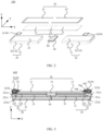
- FIG. 1 is a schematic diagram of a structure of a foldable terminal according to an embodiment of this application.
- FIG. 2 is an exploded view of the foldable terminal in FIG. 1 .
- a foldable mobile phone 100 includes a flexible display (also referred to as a foldable screen or a flexible screen) 10.
- the flexible display 10 includes, for example, an organic light-emitting diode (Organic Light Emitting Diode, OLED) display.
- OLED Organic Light Emitting Diode
- a backlight module is not required in the OLED display, and a base substrate in the OLED display may be, for example, a flexible resin material, for example, polyethylene terephthalate (Polyethylene terephthalate, PET), so that the OLED display has a bendable characteristic.
- a type of the flexible display 10 includes, but is not limited to, an OLED display. Any display that can be bent falls within the scope of protection of this application, for example, may be a liquid crystal display (Liquid Crystal Display, LCD), an LED display (including, for example, a Micro-LED display and a Mini-LED display), or the like.
- a positional relationship of the structures in the foldable mobile phone 100 is specified by using an X-axis direction, a Y-axis direction, and a Z-axis direction.
- the X-axis direction is a width direction of the foldable mobile phone 100 after being unfolded
- the Y-axis direction is a length direction of the foldable mobile phone 100 after being unfolded
- the Z-axis direction (also referred to as a first direction) is a thickness direction of the foldable mobile phone 100 after being unfolded.
- the foldable mobile phone 100 further includes structural components.
- the structural components include a first body 20, a second body 30, and a rotating shaft structure 40.
- the first body 20 and the second body 30 are located on two sides of the rotating shaft structure 40, and the rotating shaft structure 40 is connected to the first body 20 and the second body 30.
- the first body 20, the rotating shaft structure 40, and the second body 30 may be configured for carrying the flexible display 10.
- the first body 20 and the second body 30 may respectively rotate around an axis S0 of the rotating shaft structure 40, to implement a folded state, an unfolded state, or the like of the flexible display 10, i.e., to implement a folded state, an unfolded state, or the like of the foldable mobile phone 100.
- the first body 20 and the second body 30 are symmetrically distributed about the axis S0.
- a part of the flexible display 10 that is bent is a bent display section 12.
- parts of the flexible display 10 located on two sides of the bent display section 12 are respectively a first flat display section 11 and a second flat display section 13.
- an angle between a plane in which the first flat display section 11 is located and a plane in which the second flat display section 13 is located changes with the bending of the bent display section 12, for example, changes from 180° to 0°.
- first body 20 and the second body 30 may be folded in a light-emitting direction of the flexible display 10, or may be folded in a direction opposite to the light-emitting direction of the flexible display 10. This is not limited in the embodiments of this application.
- the foldable mobile phone 100 can be folded at a plurality of positions.
- the structural components may include a plurality of rotating shaft structures 40 and a plurality of bodies.
- two rotating shaft structures 40 and three bodies may be included, and two adjacent bodies are connected by one rotating shaft structure 40.
- the foldable mobile phone 100 has two folding positions.
- the structural components include at least one rotating shaft structure 40 and at least two bodies, and two adjacent bodies are connected by one rotating shaft structure 40.
- the embodiments of this application are all described by using an example in which the structural components include one rotating shaft structure 40 and two bodies (i.e., the first body 20 and the second body 30).
- the foldable mobile phone 100 is folded in a longitudinal direction (i.e., the Y-axis direction), i.e., the foldable mobile phone 100 forms a left screen and a right screen when being folded, is used for description, which does not constitute a limitation on this application.
- the foldable mobile phone 100 may be further folded in a transverse direction (i.e., the X-axis direction), i.e., the foldable mobile phone 100 forms an upper screen and a lower screen when being folded.
- a transverse direction i.e., the X-axis direction
- FIG. 3 is a cross-sectional view of the foldable terminal in FIG. 1 in an AA' direction.
- the first body 20 includes a first housing 21 and a first middle frame 22.
- the second body 30 includes a second housing 31 and a second middle frame 32.
- the first housing 21 may be a rear cover (also referred to as a battery cover) of the foldable mobile phone 100, or may be a display (for example, an LCD display, an OLED display, an LED display, among other types) configured for display, which is not limited in the embodiments of this application.
- the second housing 31 may be a rear cover (also referred to as a battery cover) of the foldable mobile phone, or may be a display configured for display, which is not limited in the embodiments of this application.
- the first middle frame 22 includes a first exterior member (a structure of the first middle frame 22 exposed from an outer side) 221 and a first support member 222 fixedly connected to the first exterior member.
- the first exterior member 221 and the first support member 222 may be integrally formed, or may be separately formed and then fixed together by welding, bonding, or the like.
- the second middle frame 32 includes a second exterior member (a structure of the second middle frame 32 exposed from an outer side) 321 and a second support member 322 fixedly connected to the second exterior member 321.
- the second exterior member 321 and the second support member 322 may be integrally formed, or may be separately formed and then fixed together by welding, bonding, or the like.
- the first exterior member 221 includes a first outer surface 221a, a first upper side wall 221b, a first inner surface 221c, and a first lower side wall 221d that are sequentially connected.
- the first upper side wall 221b and the first lower side wall 221d are disposed opposite to each other in the Z-axis direction.
- the first outer surface 221a and the first inner surface 221c are connected to the first upper side wall 221b and the first lower side wall 221d, and are disposed opposite to each other.
- the first support member 222 is disposed on the first inner surface 221c, and is located between the flexible display 10 and the first housing 21.
- the second exterior member 321 includes a second outer surface 321a, a second upper side wall 321b, a second inner surface 321c, and a second lower side wall 321d that are sequentially connected.
- the second upper side wall 321b and the second lower side wall 321d are disposed opposite to each other in the Z-axis direction.
- the second outer surface 321a and the second inner surface 321c are connected to the second upper side wall 321b and the second lower side wall 321d, and are disposed opposite to each other.
- the second support member 222 is disposed on the second inner surface 321c, and is located between the flexible display 10 and the second housing 31.
- the flexible display 10, the first inner surface 221c of the first exterior member 221, and the first housing 21 define a first accommodation cavity 23, and the flexible display 10, the second inner surface 321c of the second exterior member 321, and the second housing 31 define a second accommodation cavity 33.
- Structures such as a printed circuit board, a flexible circuit board, a functional device, and a battery are disposed in the first accommodation cavity 23 and the second accommodation cavity 33.
- the functional device includes, for example, a display driver module, a camera, or the like.
- the flexible display 10 and some structures in the accommodation cavities are supported by the first support member 222 of the first middle frame 22 and the second support member 322 of the second middle frame 32.
- rotating shaft structure 40 in the embodiments of this application are simplified schematic diagrams of structures.
- a specific structure of the rotating shaft structure 40 is not limited in the embodiments of this application, as long as the rotation of the first body 20 and the second body 30 can be implemented to implement a folded state, an unfolded state, or the like of the foldable mobile phone 100.
- the rotating shaft structure 40 includes structures known to a person skilled in the art, for example, a shaft cover, a synchronization mechanism, two door plates, and a damping mechanism.
- a shaft cover for example, a shaft cover, a synchronization mechanism, two door plates, and a damping mechanism.
- the foldable mobile phone 100 further includes an attraction structure 60.
- the two attraction structures 60 include a first attraction structure 61 and a second attraction structure 62.
- the first attraction structure 61 is located in the first accommodation cavity 23, and the second attraction structure 62 is located in the second accommodation cavity 33.
- the specific types of the first attraction structure 61 and the second attraction structure 62 are not limited in the embodiments of this application, as long as the foldable mobile phone 100 is kept in a folded state through the attractive force between the first attraction structure 61 and the second attraction structure 62.
- the first attraction structure 61 and the second attraction structure 62 are magnetic components.
- the foldable mobile phone 100 further includes a screen decorating member 50, located on a side of the flexible display 10 away from the bodies, and configured for blocking a gap between the flexible display 10 and the exterior members, that is, configured for blocking a gap between the first inner surface 221c of the first exterior member 221 and an edge of the flexible display 10 and blocking a gap between the second inner surface 321c of the second exterior member 321 and the edge of the flexible display 10.
- a screen decorating member 50 located on a side of the flexible display 10 away from the bodies, and configured for blocking a gap between the flexible display 10 and the exterior members, that is, configured for blocking a gap between the first inner surface 221c of the first exterior member 221 and an edge of the flexible display 10 and blocking a gap between the second inner surface 321c of the second exterior member 321 and the edge of the flexible display 10.
- the screen decorating member 50 has a large hardness and strength, for example, a hardness greater than or equal to 95°.
- the material of the screen decorating member 50 is not limited in the embodiments of this application, and may be selected by a person skilled in the art according to an actual case.
- the material of the screen decorating member 50 includes, for example, a thermoplastic polyurethane elastomer (Thermoplastic polyurethanes, TPU), polycarbonate (Polycarbonate, PC), poly(ether-ether-ketone) (poly(ether-ether-ketone), PEEK), and the like.
- carbon fiber or glass fiber with a volume ratio of less than 70% may be mixed in all the foregoing materials to further increase the strength of the screen decorating member 50.
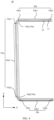
- FIG. 4 is a schematic diagram of a front structure of a screen decorating member according to an embodiment of this application.
- the screen decorating member 50 has a non-closed annular structure.
- a shape of the screen decorating member 50 is, for example, a "C" shape, i.e., a shape of a projection of the screen decorating member 50 onto a plane formed by an X axis and a Y axis when the flexible display 10 is in an unfolded state is a "C" shape.
- the screen decorating member 50 includes a first decorating section 50a and two second decorating sections 50b.
- the first decorating section 50a includes a first end portion 50a1, a second end portion 50a2, and a main body portion 50a3 located between the first end portion 50a1 and the second end portion 50a2.
- the second decorating section 50b includes a first end portion 50b1, a second end portion 50b2, and a main body portion 50b3 located between the first end portion 50b1 and the second end portion 50b2.
- the two second decorating sections 50b extend in a same direction, for example, both extend in the X-axis direction.
- An extension direction of the first decorating section 50a is different from an extension direction of the second decorating section 50b.
- the extension direction of the first decorating section 50a is the Y-axis direction.
- the two second decorating sections 50b are disposed opposite to each other in the Y-axis direction, and the first decorating section 50a is located between the two second decorating sections 50b.
- the first end portion 50b1 of one of the second decorating sections 50b is adjacent to the first end portion 50a1 of the first decorating section 50a
- the first end portion 50b1 of the other second decorating section 50b is adjacent to the second end portion 50a2 of the first decorating section 50a.
- the screen decorating member 50 further includes two bent sections 50d.
- the two bent sections 50d are respectively a first bent section 50d1 and a second bent section 50d2.
- the first bent section 50d1 is configured for connecting the first end portion 50a1 of the first decorating section 50a to the first end portion 50b1 of one of the second decorating sections 50b, so that the first decorating section 50a is connected to the second decorating section 50b by a smooth transition.
- the second bent section 50d2 is configured for connecting the second end portion 50a2 of the first decorating section 50a to the first end portion 50b1 of the other second decorating section 50b, so that the first decorating section 50a is connected to the second decorating section 50b by a smooth transition.
- the one second decorating section 50b, the first bent section 50d1, the first decorating section 50a, the second bent section 50d2, and the other second decorating section 50b may be integrally formed, or may be separately formed and then fixedly connected by welding, bonding, or the like.
- two screen decorating members 50 are provided, and the two screen decorating members 50 are a first screen decorating member 53 and a second screen decorating member 54.
- the first screen decorating member 53 is located on a side of the first upper side wall 221b away from the first lower side wall 221d, and is configured for blocking a gap between the first inner surface 221c of the first exterior member 221 and an edge of the first flat display section 11 of the flexible display 10.
- the second screen decorating member 54 is located on a side of the second upper side wall 321b away from the second lower side wall 221d, and the second screen decorating member 54 is configured for blocking a gap between the second inner surface 321c of the second exterior member 321 and an edge of the second flat display section 13 of the flexible display 10.
- the first screen decorating member 53 and the second screen decorating member 54 are symmetrically distributed about the axis S0.
- each of the first screen decorating member 53 and the second screen decorating member 54 includes a fixing portion 51 and a blocking portion 52.
- the blocking portion 52 and the fixing portion 51 are both non-closed annular structures, and the fixing portion 51 is disposed around the blocking portion 52.
- shapes of the blocking portion 52 and the fixing portion 51 are, for example, both "C" shapes.
- the blocking portion 52 and the fixing portion 51 may be integrally formed and fixedly connected. Certainly, the blocking portion 52 and the fixing portion 51 may alternatively be separately formed and fixed together by welding, bonding, or the like.
- the fixing portion 51 of the first screen decorating member 53 is configured for fixing the first screen decorating member 53 on the first exterior member 221, so that the blocking portion 52 of the first screen decorating member 53 blocks the gap between the first inner surface 221c of the first exterior member 221 and the edge of the flexible display 10.
- the fixing portion 51 of the second screen decorating member 54 is configured for fixing the second screen decorating member 54 on the second exterior member 321, so that the blocking portion 52 of the second screen decorating member 54 blocks the gap between the second inner surface 321c of the second exterior member 321 and the edge of the flexible display 10.
- each of the first screen decorating member 53 and the second screen decorating member 54 includes a first decorating surface 50f and a second decorating surface 50g that are opposite to each other.
- the first decorating surface 50f of the first screen decorating member 53 is located on a side of the second decorating surface 50g away from the first upper side wall 221b of the first exterior member 221
- the first decorating surface 50f of the second screen decorating member 54 is located on a side of the second decorating surface 50g away from the first upper side wall 221b of the second exterior member 321.
- FIG. 5 is a schematic diagram of a rear structure of a screen decorating member according to an embodiment of this application.
- the second decorating surface 50g of the screen decorating member 50 is locally recessed toward the edge of the flexible display 10 in the Z-axis direction to form a non-closed annular notch 50h.
- a part of the screen decorating member 50 corresponding to the annular notch 50h is the blocking portion 52.
- an orthographic projection of the annular notch 50h onto the plane formed by the X axis and the Y axis coincides with an orthographic projection of the blocking portion 52 onto the plane formed by the X axis and the Y axis, and another part of the screen decorating member 50 other than the blocking portion 52 is the fixing portion 51.
- the annular notch 50h is provided, so that a thickness of the blocking portion 52 is less than a thickness of the fixing portion 51 in the Z-axis direction. In this way, the edge of the flexible display 10 may extend into the annular notch 50h, to block a gap between the edge of the flexible display 10 and an inner surface of an exterior member by using the blocking portion 52, and protect the edge of the flexible display 10.
- the second decorating surface 50g of the fixing portion 51 locally protrudes in the Z-axis direction to form at least one protruding portion 511.
- a side wall of the exterior member is locally recessed to form a recessed portion matching the protruding portion 511.
- the protruding portion 511 is embedded in the recessed portion, so that the fixing portion 51 of the screen decorating member 50 is fixed on the exterior member.
- the first upper side wall 221b of the first exterior member 221 is locally recessed to form a recessed portion matching the protruding portion 511 corresponding to the fixing portion 51 of the first screen decorating member 53.
- the protruding portion 511 is embedded in the recessed portion, so that the fixing portion 51 of the first screen decorating member 53 is fixed to the first exterior member 221.
- the fixing portion 51 may be fixed to the first exterior member 221 by an interference fit between the protruding portion 511 and the recessed portion, or the fixing portion 51 of the first screen decorating member 53 may be fixed to the first exterior member 221 by bonding (glue or another viscous material).
- the second upper side wall 321b of the second exterior member 321 is locally recessed to form a recessed portion matching the protruding portion 511 corresponding to the fixing portion 51 of the second screen decorating member 54.
- the protruding portion 511 is embedded in the recessed portion, so that the fixing portion 51 of the second screen decorating member 54 is fixed to the second exterior member 321.
- the fixing portion 51 may be fixed to the second exterior member 321 by an interference fit between the protruding portion 511 and the recessed portion, or the fixing portion 51 of the second screen decorating member 54 may be fixed to the second exterior member 321 by bonding (glue or another viscous material).
- one protruding portion 511 may be provided, and the protruding portion 511 may be a semi-closed annular protruding portion 511.
- a plurality of protruding portions 511 may be provided, and the plurality of protruding portions 511 may be evenly distributed on the second decorating surface 50g, so that the fixing portion 51 of the screen decorating member 50 is fixed to the exterior member more stably.
- FIG. 6 is a schematic diagram of a structure of a foldable terminal in a folded state according to an embodiment of this application.
- the first screen decorating member 53 only blocks the gap between the first inner surface 221c of the first exterior member 221 and the edge of the first flat display section 11 of the flexible display 10
- the second screen decorating member 54 only blocks the gap between the second inner surface 321c of the second exterior member 321 and the edge of the second flat display section 13 of the flexible display 10, and does not block an edge of the bent display section 12 of the flexible display 10. Therefore, during folding, a position (for example, a DD region in FIG. 1 and FIG.
- the foldable mobile phone 100 falls in a folded state (the angle between the plane in which the first flat display section 11 is located and the plane in which the second flat display section 13 is located is greater than or equal to 0° and less than 180°), the foldable mobile phone 100 is subjected to an impact force of the ground or another object. Under the action of the impact force, the flexible display 10 and the screen decorating member 50 displace and/or vibrate, so that the flexible display 10 is in contact with the screen decorating member 50. An area of the second end portion 50b2 is small.
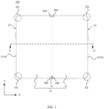
- the fixing portion 51 at the first bent section 50d1, the fixing portion 51 at the second bent section 50d2 of the first screen decorating member 53, the fixing portion 51 at the first bent section 50d1, and the fixing portion 51 at the second bent section 50d2 of the second screen decorating member 54 may collide with four corners (for example, EE regions in FIG. 1 ) of the flexible display 10, resulting in damage to the flexible display 10.
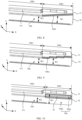
- FIG. 7 is an enlarged view of a BB region of the screen decorating member in FIG. 5 according to an embodiment of this application.
- a width W1 of the notch 50h located at the second end portion 50b2 is greater than a width W2 of the notch 50h located at the main body portion 50b3.
- a size of the notch 50h of the second end portion 50b2 is increased, i.e., a width of the fixing portion 51 of the second end portion 50b2 is reduced.
- the second end portion 50b2 With such an arrangement, strength of the second end portion 50b2 can be reduced.
- the second end portion 50b2 with reduced strength releases partial stress after impacting the bent display section 12 of the flexible display 10, thereby achieving the objective of protecting the flexible display 10.
- the structure is simple, the process steps are simple, and the costs are low.
- a width of the notch 50h is a size of the notch 50h in a direction (also referred to as a second direction) of the fixing portion 51 pointing to the blocking portion 52.
- a direction also referred to as a second direction
- FIG. 8 is a schematic diagram of a partial structure of a screen decorating member according to an embodiment of this application.
- the width of the notch 50h decrements on a gradient in a direction (also referred to as a third direction) of the second end portion 50b2 pointing to the main body portion 50b3.
- the second end portion 50b2 can further release partial stress after impacting the bent display section 12 of the flexible display 10, thereby protecting the flexible display 10.
- FIG. 9 is a schematic diagram of a partial structure of a screen decorating member according to an embodiment of this application. As shown in FIG. 9 , the side wall 50h1 of the notch 50h may alternatively be a stepped surface.
- the second decorating surface 50g of the fixing portion 51 locally protrudes in the Z-axis direction to form at least one protruding portion 511.
- a side wall of the exterior member is locally recessed to form a recessed portion matching the protruding portion 511.
- the protruding portion 511 is embedded in the recessed portion, so that the fixing portion 51 of the screen decorating member 50 is fixed on the exterior member.
- a size (i.e., a thickness) of the protruding portion 511 at the second end portion 50b2 in the Z-axis direction is less than a size (i.e., a thickness) of the protruding portion 511 at the main body portion 50b3 in the Z-axis direction.
- the following accompanying drawings are also described by using an example in which the size of the protruding portion 511 at the second end portion 50b2 in the Z-axis direction is less than the size of the protruding portion 511 at the main body portion 50b3 in the Z-axis direction.
- FIG. 10 is a schematic diagram of a partial structure of another screen decorating member according to an embodiment of this application.
- the width W1 of the notch 50h (also referred to as a first notch) located at the second end portion 50b2 is greater than the width W2 of the notch 50h (also referred to as a second notch) located at the main body portion 50b3.
- the notch 50h of the second end portion 50b2 includes a first part 50h2 and a second part 50h3.
- the first part 50h2 is a portion with a same width as the notch 50h of the main body portion 50b3, and the second part 50h3 is a remaining part of the notch 50h of the second end portion 50b2 other than the first part 50h2.
- a soft structure 55 is disposed at the second part 50h3 of the second end portion 50b2. To be specific, the soft structure 55 is disposed in a part of the notch in the notch 50h of the second end portion 50b2 that has a larger width than the width W2 of the notch 50h of the main body portion 50b3.
- a hardness of the soft structure 55 is less than a hardness of the screen decorating member 50.
- the hardness of the soft structure 55 is greater than or equal to 60° and less than or equal to 65°.
- the material of the soft structure 55 is not limited in the embodiments of this application, may be selected by a person skilled in the art according to an actual case, and may be, for example, plastic, soft glue, or the like.
- the soft structure 55 is disposed at the second part 50h3 of the second end portion 50b2, i.e., the width of the fixing portion 51 is still an equal-width design (only a material in a partial region at the second end portion 50b2 is different). With such an arrangement, a common material is still kept at the appearance of the screen decorating member 50 to keep the appearance effect and the overall strength of the screen decorating member 50. In addition, when the foldable mobile phone 100 falls in a folded state, the soft structure 55 has an instantaneous deformation to release stress, thereby achieving the objective of protecting the flexible display 10.
- the width of the notch 50h is a size of the notch 50h in the direction of the fixing portion 51 pointing to the blocking portion 52.
- the width of the fixing portion 51 is a size of the fixing portion 51 in the direction of the fixing portion 51 pointing to the blocking portion 52.
- FIG. 11 is a schematic diagram of a partial structure of another screen decorating member according to an embodiment of this application.
- the width W3 of the soft structure 55 decrementing on a gradient may be that a surface of the soft structure 55 in contact with the side wall 50h1 of the notch 50h is an inclined surface.
- the surface of the soft structure 55 in contact with the side wall 50h1 of the notch 50h is an inclined surface
- the surface of the soft structure 55 in contact with the side wall 50h1 of the notch 50h may alternatively be a stepped surface (not shown in the figure).
- FIG. 12 is a schematic diagram of a partial structure of another screen decorating member according to an embodiment of this application.
- the blocking portion 52 includes a blocking surface facing the flexible display 10.
- the blocking surface and the side wall of the fixing portion 51 protruding from the blocking portion 52 define the notch 50h, and at least one groove is opened in the blocking surface at the second end portion 50b2.
- the strength of the second end portion 50b2 can be reduced.
- the second end portion 50b2 with reduced strength releases partial stress through the groove 56 after impacting the bent display section 12 of the flexible display 10, thereby achieving the objective of protecting the flexible display 10.
- an opening of the groove 56 is located at the second decorating surface 50g instead of being located at the first decorating surface 50h. Therefore, the appearance effect of the second end portion 50b2 is not affected, the structure is simple, the process steps are simple, and the costs are low.
- FIG. 13 is a schematic diagram of a partial structure of another screen decorating member according to an embodiment of this application. As shown in FIG.
- the shape of the orthographic projection of the groove 56 onto the plane formed by the X axis and the Y axis may alternatively be an elliptical shape, a circular shape (not shown in the figure), a square shape (not shown in the figure), a triangular shape (not shown in the figure), or the like.
- the shape of the orthographic projection of the groove 56 onto the plane formed by the X axis and the Y axis is an elliptical shape, a circular shape, or the like, the groove 56 can be kept from being damaged due to stress concentration at corners of the groove, to avoid causing damage to the blocking portion 52.
- FIG. 14 is a schematic diagram of a partial structure of another screen decorating member according to an embodiment of this application. As shown in FIG. 14 , a plurality of rows of grooves 56 may alternatively be provided.
- the shape of the orthographic projection of the groove 56 onto the plane formed by the X axis and the Y axis is a rectangular shape and one row of grooves 56 are provided is used for description, and a quantity of the grooves 56 in the following example is also merely an example.
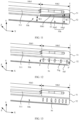
- FIG. 15 is a schematic diagram of a partial structure of another screen decorating member according to an embodiment of this application.
- a volume of the groove 56 in the second end portion 50b2 gradually decreases in a unit area of the blocking surface.
- the unit area of the blocking surface is an area parallel to the plane formed by the X axis and the Y axis.
- a volume of the groove 56 in a unit area S0 of the blocking surface at an edge of the second end portion 50b2 away from the main body portion 50b3 is greater than a total volume of the groove 56 in the unit area S0 of the blocking surface at an edge of the second end portion 50b2 in contact with the main body portion 50b3.
- the volume of the groove 56 is a sum of adding of volumes of all the grooves 56 in the unit area of the blocking surface. For example, when one groove 56 is provided in the unit area of the blocking surface, a volume of the groove 56 is a volume of the groove 56. When a plurality of grooves 56 are provided in the unit area of the blocking surface, a volume of the grooves 56 is a sum of volumes of the grooves 56.
- a volume of the groove 56 in the second end portion 50b2 gradually decreases in a unit area of the blocking surface in a plurality of manners.
- a plurality of grooves 56 are provided. A distance between two adjacent grooves 56 gradually increases in the direction of the second end portion 50b2 pointing to the main body portion 50b3.
- the six grooves 56 include a first groove 561, a second groove 562, a third groove 563, a fourth groove 564, a fifth groove 565, and a sixth groove 566.
- a distance between the first groove 561 and the second groove 562 is L1
- a distance between the second groove 562 and the third groove 563 is L2
- a distance between the third groove 563 and the fourth groove 564 is L3
- a distance between the fourth groove 564 and the fifth groove 565 is L4
- a distance between the fifth groove 565 and the sixth groove 566 is L5, and L5 > L4 > L3 > L2 > L1.
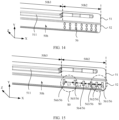
- FIG. 16 is a schematic diagram of a partial structure of another screen decorating member according to an embodiment of this application. As shown in FIG. 16 , a plurality of grooves 56 are provided. Volumes of the plurality of grooves 56 gradually decrease in the direction of the second end portion 50b2 pointing to the main body portion 50b3.
- the five grooves 56 include a first groove 561, a second groove 562, a third groove 563, a fourth groove 564, and a fifth groove 565.
- a volume of the first groove 561 is V1
- a volume of the second groove 562 is V2
- a volume of the third groove 563 is V3
- a volume of the fourth groove 564 is V4
- a volume of the fifth groove 565 is V5, and V1 > V2 > V3 > V4 > V5.
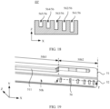
- lengths (as shown in FIG. 16 ), widths (as shown in FIG. 17 ), and/or depths (as shown in FIG. 18 ) of the first groove 561, the second groove 562, the third groove 563, the fourth groove 564, and the fifth groove 565 may gradually decrease, so that the volumes of the plurality of grooves 56 gradually decrease in the direction of the second end portion 50b2 pointing to the main body portion 50b3.
- a length of the groove 56 is a size of the groove 56 in the direction (i.e., the X-axis direction shown in FIG. 15 ) of the second end portion 50b2 pointing to the main body portion 50b3.
- a width of the groove 56 is a size of the groove 56 in the direction (i.e., the Y-axis direction shown in FIG. 15 ) of the fixing portion 51 pointing to the blocking portion 52.
- a depth of the groove 56 is a size of the groove 56 in the Z-axis direction shown in FIG. 15 .
- FIG. 19 is a schematic diagram of a partial structure of another screen decorating member according to an embodiment of this application.
- FIG. 19 is a schematic diagram of a partial structure of another screen decorating member according to an embodiment of this application.
- FIG. 20 is a cross-sectional view of the screen decorating member in FIG. 19 in an II' direction. As shown in FIG. 19 and FIG. 20 , the distance between two adjacent grooves 56 gradually increases in the direction of the second end portion 50b2 pointing to the main body portion 50b3, and the depths of the plurality of grooves 56 gradually decrease.
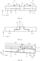
- FIG. 21 is a schematic diagram of a partial structure of another screen decorating member according to an embodiment of this application.
- FIG. 22 is a cross-sectional view of the screen decorating member in FIG. 21 in a JJ' direction.
- a hardness of a material of the blocking portion 52 at the second end portion 50b2 is less than a hardness of a material of the blocking portion 52 at the main body portion 50b3.
- the material of the blocking portion 52 at the second end portion 50b2 is different from the material of the blocking portion 52 at the main body portion 50b3.
- the material of the blocking portion 52 at the second end portion 50b2 is, for example, rubber, which may be specifically referred to as, for example, a thermoplastic polyurethane elastomer (Thermoplastic polyurethanes, TPU).
- TPU thermoplastic polyurethanes
- the blocking portion 52 at the second end portion 50b2 is soft, when the foldable mobile phone 100 falls in a folded state, the soft blocking portion 52 has an instantaneous deformation under the action of impact to release stress, thereby achieving the objective of protecting the flexible display 10.
- FIG. 23 is another cross-sectional view of the screen decorating member in FIG. 21 in a JJ' direction. As shown in FIG. 23 , a protective layer 57 is disposed on the first decorating surface 50f of the screen decorating member 50.
- the protective layer 57 blocks the entire first decorating surface 50f of the screen decorating member 50, to block a gap or seam trace at a connection between the blocking portion 52 of the second end portion 50b2 and the blocking portion 52 of the main body portion 50b3 caused by splicing, so that the screen decorating member 50 has a consistent appearance.
- a specific structure of the second end portion 52b2 is described above.
- a soft material is disposed (i.e., a change in material) or a groove is provided (i.e., a change in structure) at the second end portion 52b to implement the protection of the bent display section 12 of the flexible display 10, to avoid a case that when the foldable mobile phone 100 falls in a folded state, the second end portion 50b2 of the second decorating section 50b of the screen decorating member 50 punctures the bent display section 12 of the flexible display 10 under the action of impact, causing damage to the flexible display 10.
- FIG. 24 is a schematic diagram of a partial structure of another screen decorating member according to an embodiment of this application. As shown in FIG. 24 , in the second decorating section 50b, the width W1 of the notch 50h located at the second end portion 50b2 is greater than the width W2 of the notch 50h located at the main body portion 50b3, and at least one groove 56 is opened in the blocking portion 52 located at the second end portion 50b2.
- the width of the groove 56 may alternatively extend, i.e., extend into a part of the notch in the notch 50h of the second end portion 50b2 that has a larger width than the width W2 of the notch 50h of the main body portion 50b3, as shown in FIG. 25 .
- the length of the second end portion 52b2 in the X-axis direction is not limited in the embodiments of this application, and may be set by a person skilled in the art according to an actual case.
- the length of the second end portion 52b2 is greater than or equal to 0.5 mm and less than or equal to 10 mm. In this way, the overall strength of the screen decorating member 50 is not affected due to an excessively large length of the second end portion 52b2, and the effect of stress release is kept from failing due to an excessively small length of the second end portion 52b2.
- the length of the second end portion 52b is set between 0.5 mm and 10 mm, so that while good strength is ensured, stress can be released, to avoid a case that when the foldable mobile phone 100 falls in a folded state, the second end portion 50b2 of the second decorating section 50b of the screen decorating member 50 punctures the bent display section 12 of the flexible display 10 under the action of impact to cause damage to the flexible display 10.
- the first screen decorating member 53 only blocks the gap between the first inner surface 221c of the first exterior member 221 and the edge of the first flat display section 11 of the flexible display 10
- the second screen decorating member 54 only blocks the gap between the second inner surface 321c of the second exterior member 321 and the edge of the second flat display section 13 of the flexible display 10, and does not block the edge of the bent display section 12 of the flexible display 10 (i.e., a gap exists between the second end portion 50b2 of the second decorating section 50b of the first screen decorating member 53 and the second end portion 50b2 of the second decorating section 50b of the second screen decorating member 54 in the X-axis direction), affecting the appearance.
- FIG. 26 is a diagram of a position relationship among a first screen decorating member, a second screen decorating member, and a blocking member according to an embodiment of this application.
- FIG. 27 is a cross-sectional view of the first screen decorating member, the second screen decorating member, and the blocking member in FIG. 26 in an LL' direction.
- a blocking member 70 is disposed between the second end portion 50b2 of the second decorating section 50b in the first screen decorating member 53 and the second end portion 50b2 of the second decorating section 50b in the second screen decorating member 54 in the X-axis direction.
- the blocking member 70 includes a first section 71, a second section 73, and a third section 72 connecting the first section 71 and the second section 73.
- FIG. 28 is a schematic diagram of a partial structure of a screen decorating member and a blocking member according to an embodiment of this application.
- the third section 72 is located, for example, at the notch 50h of the second end portion 50b2.
- the blocking portion 52, the edge of the flexible display 10, and the third section 72 are sequentially disposed in the Z-axis direction.
- the third section 72 may be located only in the first part 50h2 (as shown in FIG. 29 ).
- the first part 50h2 is a part of the notch 50h of the second end portion 50b2 having a same width as the notch 50h of the main body portion 50b3 (as shown in FIG. 7 ), or may be located at the first part 50h2 and the second part 50h3 (as shown in FIG. 28 ).
- the second part 50h3 is a remaining part of the notch 50h of the second end portion 50b2 other than the first part 50h2 (as shown in FIG. 7 ). It may be understood that, when the third section 72 is located at the first part 50h2 and the second part 50h3 (shown in FIG.
- a width of the second part 50h3 may be further increased to meet a requirement of reducing the strength of the second end portion 50b2 when the foldable terminal includes the blocking member 70 and the third section 72 is located at the first part 50h2 and the second part 50h3.
- a width of the soft structure 55 is also correspondingly reduced (i.e., the soft structure does not fill up the entire second part 50h3), to avoid the third section 72 of the blocking member 70.
- FIG. 30 is a partial enlarged view of a CC region in the screen decorating member in FIG. 5 .
- a width W4 of the notch 50h located at the bent section 50d is greater than a width W2 of the notch 50h located at the first end portion 50b1 and a width W5 of the notch 50h located at the first decorating section 50a.
- the size of the notch 50h at the bent section 50d increases, i.e., the width of the fixing portion 51 at the bent section 50d decreases.
- the width W2 of the notch 50h located at the first end portion 50b1 is, for example, the same as the width W5 of the notch 50h located at the first decorating section 50a.
- the bent section 50d includes a first edge 50d1 and a second edge 50d2, the first edge 50d1 is in contact with the first end portion 50b1 of the second decorating member 50b, and the second edge 50d2 is in contact with the first decorating member 50a.
- the width of the notch 50h gradually decreases from a preset position of the bent section 50d to the first edge 50d1 thereof, the width of the notch 50h gradually decreases from the preset position of the bent section 50d to the second edge 50d2, and the side wall 50h1 (i.e., the side wall of the fixing portion 51 at the bent section 50d) of the notch 50h is a smooth curved surface.
- a specific position of the preset position in the bent section 50d is not limited in the embodiments of this application, and may be set by a person skilled in the art according to an actual case.
- the preset position is a position that is in the bent section 50d and that has a distance to the first edge 50d1 equal to a distance to the second edge 50d2.
- the preset position is a position that is in the bent section 50d and that has a distance to the first edge 50d1 greater than a distance to the second edge 50d2.
- the preset position is a position that is in the bent section 50d and that has a distance to the first edge 50d1 less than a distance to the second edge 50d2.
- the preset position is the position that is in the bent section 50d and that has the distance to the first edge 50d1 equal to the distance to the second edge 50d2.
- the width of the notch 50h gradually decreases from the preset position to the edge (the first edge 50d1 or the second edge 50d2)
- a corner position of the flexible display 10 collides with the fixing portion 51 located at the bent section 50d to cause damage to the flexible display 10 can be avoided, and the overall strength of the screen decorating member 50 can be ensured.
- FIG. 31 is a schematic top view of a structure of a bent section according to an embodiment of this application.
- the width W4 of the notch 50h located at the bent section 50d is greater than the width W2 of the notch 50h located at the first end portion 50b1 and the width W5 of the notch 50h located at the first decorating section 50a.
- the notch 50h (also referred to as a third notch) of the bent section 50d includes a third part 50h4 and a fourth part 50h5.
- the third part 50h4 is a part having a same width as the notch 50h (also referred to as a fourth notch) of the first end portion 50b1 and/or having a same width as the notch 50h (also referred to as a fifth notch) of the first decorating section 50a.
- the fourth part 50h5 is a remaining part other than the third part 50h4 in the notch 50h of the bent section 50d.
- a soft structure 65 is disposed at the fourth part 50h5. To be specific, in the notch 50h of the bent section 50d, the soft structure 65 is disposed in the part of notch having a larger width than the notch 50h of the first end portion 50b1 and/or having a larger width than the notch 50h of the first decorating section 50a.
- a hardness and a material of the soft structure 65 are the same as those in the foregoing examples. For details, refer to the foregoing examples, and details are not described herein again.
- the soft structure 65 is disposed at the fourth part 50h5, i.e., the width of the fixing portion 51 at the bent section 50d is still an equal-width design (only a material in a partial region is different). With such an arrangement, the overall strength of the screen decorating member 50 can be kept. In addition, when the foldable mobile phone 100 falls in an unfolded state, the soft structure 65 has an instantaneous deformation to release stress, thereby achieving the objective of protecting the edge of the flexible display 10.
- the width of the notch 50h gradually decreases from the preset position of the bent section 50d to the first edge 50d1 thereof, and the width of the notch 50h gradually decreases from the preset position of the bent section 50d to the second edge 50d2 (as shown in FIG. 30 ). Therefore, when the soft structure 65 is disposed, a width W6 of the soft structure 65 gradually decreases from the preset position of the bent section 50d to the second edge 50d2, and the width W6 of the soft structure 65 gradually decreases from the preset position of the bent section 50d to the first edge 50d1.
- a shape of a projection of the soft structure 65 onto the plane formed by the X axis and the Y axis is, for example, a "crescent" shape.
- FIG. 32 is a schematic diagram of a structure of a fixing portion at a bent section according to an embodiment of this application, specifically, a part of the fixing portion 51 higher than the blocking portion 52 (in the Z-axis direction) at the bent section 50d.
- at least one groove 66 is opened in a side wall (i.e., the side wall 50h1 of the notch 50h) of the fixing portion 51.
- the groove 66 is a structure formed by the side wall 50h1 being locally recessed in a direction of the blocking portion 52 pointing to the fixing portion 51.
- the structure is simple, the process steps are simple, and the costs are low.
- FIG. 33 is a schematic diagram of a structure of another fixing portion at a bent section according to an embodiment of this application. As shown in FIG.
- the shape of the orthographic projection of the groove 66 onto the plane formed by the X axis and the Y axis may alternatively be an elliptical shape, a circular shape (not shown in the figure), a square shape (not shown in the figure), a triangular shape (not shown in the figure), or the like.
- the shape of the orthographic projection of the groove 66 onto the plane formed by the X axis and the Y axis is an elliptical shape, a circular shape, or the like, the groove 66 can be kept from being damaged due to stress concentration at corners of the groove 66, to avoid causing damage to the fixing portion 51.
- FIG. 34 is a schematic diagram of a structure of another fixing portion at a bent section according to an embodiment of this application.
- the total volume of the grooves 66 gradually decreases in a unit area of the side wall 50h1 from the preset position of the bent section 50d to an edge (the first edge 50d1 or the second edge 50d2) thereof.
- the total volume of the grooves 66 is the same as that in the foregoing examples. For details, refer to the foregoing examples, and details are not described herein again.
- the total volume of the grooves 66 gradually decreases from the preset position of the bent section 50d to the edge (the first edge 50d1 and/or the second edge 50d2) thereof, so that while the flexible display 10 is protected, the strength of the screen decorating member 50 can be kept to the greatest extent.
- the total volume of the grooves 66 gradually decreases in a unit area of the side wall 50h1 from the preset position of the bent section 50d to an edge thereof in the unit area of the blocking surface in a plurality of manners.
- a plurality of grooves 66 are provided. A distance between two adjacent grooves 66 gradually increases from the preset position of the bent section 50d to an edge thereof.
- the five grooves 66 include a first groove 661, a second groove 662, a third groove 663, a fourth groove 664, and a fifth groove 665.
- the second groove 662, the third groove 663, and the fourth groove 664 are located between the first groove 661 and the fifth groove 665.
- the third groove 663 is located between the second groove 662 and the fourth groove 664.
- a distance between the first groove 661 and the second groove 662 is L6, a distance between the second groove 662 and the third groove 663 is L7, a distance between the third groove 663 and the fourth groove 664 is L7, a distance between the fourth groove 664 and the fifth groove 665 is L6, and L6 > L7.
- FIG. 35 is a schematic diagram of a structure of another fixing portion at a bent section according to an embodiment of this application. As shown in FIG. 35 , a plurality of grooves 66 are provided. Volumes of the plurality of grooves 66 gradually decrease from the preset position of the bent section 50d to an edge thereof.
- the five grooves 66 include a first groove 661, a second groove 662, a third groove 663, a fourth groove 664, and a fifth groove 665.
- the second groove 662, the third groove 663, and the fourth groove 664 are located between the first groove 661 and the fifth groove 665.
- the third groove 663 is located between the second groove 662 and the fourth groove 664.
- a volume of the first groove 561 is V6
- a volume of the second groove 562 is V7
- a volume of the third groove 563 is V8
- a volume of the fourth groove 564 is V7
- a volume of the fifth groove 565 is V6, and V8 > V7 > V6.
- lengths (as shown in FIG. 35 ), widths (as shown in FIG. 36 ), and/or depths (as shown in FIG. 37 ) of the first groove 661, the second groove 662, the third groove 663, the fourth groove 664, and the fifth groove 665 may gradually decrease, so that the volumes of the plurality of grooves 66 gradually decrease from the preset position of the bent section 50d to an edge thereof.
- a length of the groove 66 is a size of the groove 66 in the Z-axis direction.
- a width of the groove 66 is a size of the groove 66 in a direction from the preset position of the bent section 50d to an edge thereof.
- a depth of the groove 66 is a size of the groove 66 in the direction of the blocking portion 52 pointing to the fixing portion 51.
- the density gradually changes and the sizes gradually changes separately, so that a total volume of the grooves 66 in the bent section 50d gradually changes in a unit area from the preset position of the bent section 50d to an edge thereof.
- the density of the grooves 66 may gradually change and at the same time the sizes of the grooves 66 also gradually change, so that a total volume of the grooves 66 in the bent section 50d gradually changes in a unit area from the preset position of the bent section 50d to an edge thereof.
- a material of the fixing portion 51 at the bent section 50d is different from a material of the fixing portion 51 at the first decorating section 50a.
- a hardness of the material of the fixing portion 51 at the bent section 50d is less than a hardness of the material of the fixing portion 51 at the first decorating section 50a.
- the strength of the fixing portion 51 at the bent section 50d can be reduced. Partial stress is released through the fixing portion 51 after a corner of the flexible display 10 collides with the fixing portion 51, thereby achieving the objective of protecting the flexible display 10.
- a specific structure of the second end portion 50b2 at the second decorating member 50b and a specific structure of the bent section 50d are described above. Through the second end portion 50b2 and the bent section 50d, an effect of protecting the flexible display 10 can be achieved. In addition, strength of a partial region of the screen decorating member 50 is reduced. Therefore, through the foregoing arrangement, when the foldable mobile phone 100 is closed (folded), the frequency of an impact sound of the first decorating member 53 and the second decorating member 54 is reduced, and the timbre is deeper and steadier.
- positions at which the first decorating member 53 and the second decorating member 54 generate the largest impact sound are generally positions at which the attraction structures are disposed.
- the attraction structures are disposed in two manners.
- the attraction structures are disposed at the bent section 50d.
- the first attraction structure 61 is disposed at the bent section 50d of the first decorating member 53
- the second attraction structure 61 is disposed at the bent section 50d of the second decorating member 54.
- the attraction structures are disposed at the first decorating section 50a or the second decorating section 50b.
- the first attraction structure 61 is disposed at the first decorating section 50a or the second decorating section 50b
- the second attraction structure 62 is disposed at the first decorating section 50a or the second decorating section 50b of the second decorating member 54.
- the attraction structure is disposed at the first decorating section 50a or the second decorating section 50b, for example, disposed at the first end portion 50a1 or the second end portion 50a2 of the first decorating section 50a, or at the first end portion 50b of the second decorating section 50b.
- a distance from an edge of a side of the first end portion 50a1 of the first decorating section 50a away from the first bent section 50d1 to the first bent section 50d1 is greater than 0 mm and less than or equal to 70 mm.
- a distance from an edge of a side of the second end portion 50a2 of the first decorating section 50a away from the second bent section 50d2 to the second bent section 50d2 is greater than 0 and less than or equal to 70 mm.
- a distance from an edge of a side of the first end portion 50b of the second decorating section 50b away from the bent section 50d to the bent section 50b is greater than 0 mm and less than or equal to 30 mm.
- the attraction structure is disposed at the first end portion 50a1 of the first decorating section 50a, and a distance from the attraction structure to a second decorating section 50b closest to the attraction structure ranges from 0 mm to 70 mm, and is, for example, 20 mm, 30 mm, 40 mm, 50 mm, 60 mm, or 70 mm.
- the attraction structure is disposed at the second end portion 50a2 of the first decorating section 50a, and a distance from the attraction structure to a second decorating section 50b closest to the attraction structure ranges from 0 mm to 70 mm, and is, for example, 20 mm, 30 mm, 40 mm, 50 mm, 60 mm, or 70 mm.
- the attraction structure is disposed at the first end portion 50b of the second decorating section 50b, and a distance from the attraction structure to the bent section 50d ranges from 0 mm to 30 mm, and is, for example, 10 mm, 20 mm, or 30 mm.
- That the first attraction structure 61 is disposed at the bent section 50d of the first decorating member 53 may be that a projection of the first decorating member 53 onto the plane formed by the X axis and the Y axis overlaps a projection of the bent section 50d of the first decorating member 53 onto the plane formed by the X axis and the Y axis, or may be that a projection of the first decorating member 53 onto the plane formed by the X axis and the Y axis is closest to a projection of the bent section 50d of the first decorating member 53 onto the plane formed by the X axis and the Y axis.
- That the first attraction structure 61 is disposed at the first decorating section 50a or the second decorating section 50b may be that a projection of the first attraction structure 61 onto the plane formed by the X axis and the Y axis overlaps a projection of the first decorating section 50a or the second decorating section 50b onto the plane formed by the X axis and the Y axis, or may be that a projection of the first attraction structure 61 onto the plane formed by the X axis and the Y axis is closest to a projection of the first decorating section 50a or the second decorating section 50b onto the plane formed by the X axis and the Y axis.
- the frequency of an impact sound of the first decorating member 53 and the second decorating member 54 can be reduced, and the timbre is deeper and steadier.
- the fixing portion 51 at the position may use a grooving design (i.e., a plurality of grooves are provided at the position), a size of the notch 50h here may be increased, a soft structure may be disposed at the notch 50h, or the like.
- a specific arrangement manner thereof is similar to that of the bent section 50d.
Landscapes
- Engineering & Computer Science (AREA)
- Signal Processing (AREA)
- Microelectronics & Electronic Packaging (AREA)
- Telephone Set Structure (AREA)
- Casings For Electric Apparatus (AREA)
- Devices For Indicating Variable Information By Combining Individual Elements (AREA)
Abstract
Description
- This application claims priority to
Chinese Patent Application No. 202211633795.0, entitled "SCREEN DECORATING MEMBER AND ELECTRONIC DEVICE" filed with the China National Intellectual Property Administration on December 19, 2022 - This application relates to the technical field of electronic devices, and in particular, to a screen decorating member and an electronic device.
- With continuous development of display technologies, foldable terminals (for example, foldable mobile phones) gradually become a development trend of future mobile electronic products. A foldable terminal can obtain a large display area in an unfolded state to improve a visual effect, can obtain a small volume in a folded state to facilitate carrying by a user, and therefore becomes popular among an increasing number of users.
- A structure for implementing display of a foldable terminal is a flexible display. However, during falling of the foldable terminal, the flexible display has a problem of being vulnerable to damage due to impact from other structures of the foldable terminal.
- To resolve the foregoing technical problem, this application provides a screen decorating member and an electronic device, to avoid a problem of the flexible display being vulnerable to damage due to impact from other structures of the foldable terminal.
- According to a first aspect, embodiments of this application provide a screen decorating member in an electronic device. The electronic device includes a screen body. The screen decorating member includes a first decorating section, a second decorating section, and a bent section, and the second decorating section includes a first end portion and a second end portion. The first decorating section is connected to the first end portion of the second decorating section by the bent section, the second end portion is located on a side of the first end portion away from the bent section, and the first decorating section, the second decorating section, and the bent section are configured for being disposed around at least part of a circumference of the screen body. The bent section and/or the second end portion are/is provided with a stress buffer structure.
- The stress buffer structure is disposed at the bent section and/or the second end portion to implement the protection of the screen body, to avoid a case that when the electronic device falls, the screen body and/or the screen decoration vibrates or displaces under the action of impact and the bent section and/or the second end portion of the screen decorating member cause/causes damage to the screen body.
- For example, when the electronic device is a foldable terminal, the screen body is a flexible display. The stress buffer structure is disposed at the second end portion to implement the protection of a bent display section of the flexible display, to avoid a case that when the foldable terminal falls in a folded state, the second end portion of the second decorating section of the screen decorating member punctures the bent display section of the flexible display under the action of impact to cause damage to the flexible display, and avoid a case that when the foldable mobile phone falls in an unfolded state, the bent section collides with an edge of the flexible display to cause damage to the flexible display. In addition, with the arrangement of the stress buffer structure, the frequency of an impact sound of a middle frame when the foldable terminal is closed is reduced, and the timbre is deeper and steadier.
- For example, when the electronic device is a foldable terminal, the screen body is a flexible display. When the electronic device is a bar-type terminal, the screen body is a display.
- For example, two second decorating sections are provided, two bent sections are provided, the first decorating section is located between the two second decorating sections, one bent section is connected to the first decorating section and one of the second decorating sections, the other bent section is connected to the first decorating section and the other second decorating section, the two second decorating sections extend in a same direction, and an extension direction of the first decorating section is different from an extension direction of the second decorating section, for example, the extension direction of the first decorating section is perpendicular to the extension direction of the second decorating section.
- It should be noted that a position provided with the stress buffer structure is, but not limited to, the bent section and/or the second end portion, and any screen decorating member provided with a stress buffer structure in a region that may cause damage to the screen body falls within the scope of protection of this application.
- In some possible implementations, the electronic device further includes a housing, the screen body is disposed on a side of the housing, and the screen decorating member includes a first decorating surface and a second decorating surface that are opposite to each other in a first direction, where the first direction is a thickness direction of the screen decorating member; the second decorating surface is locally recessed in the first direction toward an edge of the screen body to form a notch; a part corresponding to the notch in the screen decorating member in the first direction is a blocking portion, and the blocking portion is configured for blocking the edge of the screen body; and another part other than the blocking portion in the screen decorating member is a fixing portion, and the fixing portion is configured for being fixed at a circumference of the housing. The structure of the screen decorating member is simple.
- For example, the housing is a body in the embodiments, is specifically a middle frame, and is more specifically an exterior member of the middle frame.
- In some possible implementations, based on that the screen decorating member includes the fixing portion and the blocking portion, the second decorating section further includes a main body portion located between the first end portion and the second end portion; the second end portion includes a first notch, and the main body portion includes a second notch; a width of the first notch is greater than a width of the second notch, the width of the notch is a size of the notch in a second direction, and the second direction is a direction of the blocking portion pointing to the fixing portion; and the first notch includes a first part and a second part that are adjacent in the second direction, the first part is a part that is in the first notch and that has a same width as the second notch, and the stress buffer structure includes the second part. To be specific, the size of the notch of the second end portion is increased, and a width of the fixing portion of the second end portion is reduced, to reduce the strength of the second end portion. The second end portion with reduced strength releases partial stress after impacting the bent display section of the flexible display, thereby achieving the objective of protecting the flexible display. In addition, because only the size of the notch is increased, the appearance effect of the second end portion is not affected, the structure is simple, the process steps are simple, and the costs are low.
- In some possible implementations, a width of the second part gradually decreases in a third direction, and the width of the fixing portion of the second end portion gradually increases, where the third direction is a direction of the second end portion pointing to the main body portion. With such an arrangement, while the overall strength of the screen decorating member is ensured, the second end portion can further release partial stress after impacting the bent display section of the flexible display, thereby protecting the flexible display.
- In some possible implementations, based on that the stress buffer structure includes the second part, a soft structure is disposed at the second part, and the stress buffer structure further includes the soft structure. The soft structure is disposed at the second part of the second end portion, i.e., the width of the fixing portion is still an equal-width design (only a material in a partial region at the second end portion is different). With such an arrangement, a common material is still kept at the appearance of the screen decorating member to keep the appearance effect and the overall strength of the screen decorating member. In addition, when the foldable terminal falls in a folded state, the soft structure has an instantaneous deformation to release stress, thereby achieving the objective of protecting the flexible display.
- In some possible implementations, based on that the stress buffer structure further includes the soft structure, when the width of the second part gradually decreases in the third direction, a width of the soft structure gradually increments on a gradient in the third direction, where the width of the soft structure is a size of the soft structure in the second direction. With such an arrangement, while the overall strength of the screen decorating member is ensured, the second end portion can further release partial stress through the soft structure after impacting the bent display section of the flexible display, thereby protecting the flexible display.
- In some possible implementations, based on that the screen decorating member includes the fixing portion and the blocking portion, the blocking portion includes a blocking surface facing the screen body; the blocking surface and a side wall of the fixing portion define the notch, and at least one groove is opened in the blocking surface at the second end portion; and the stress buffer structure includes the groove. With such an arrangement, the strength of the second end portion can be reduced. The second end portion with reduced strength releases partial stress through the groove after impacting the bent display section of the flexible display, thereby achieving the objective of protecting the flexible display. In addition, an opening of the groove is located at the second decorating surface instead of being located at the first decorating surface. Therefore, the appearance effect of the second end portion is not affected, the structure is simple, the process steps are simple, and the costs are low.
- In some possible implementations, based on that the stress buffer structure includes the groove, a volume of the groove gradually decreases in a unit area of the blocking surface in a third direction, and the third direction is a direction of the second end portion pointing to the first end portion. With such an arrangement, while the overall strength of the screen decorating member is ensured, the second end portion can further release partial stress through the soft structure after impacting the bent display section of the flexible display, thereby protecting the flexible display.
- In some possible implementations, based on that the volume of the groove gradually decreases, a plurality of grooves are provided, and a distance between two adjacent grooves gradually increases in the third direction. To be specific, the density of the grooves is reduced, so that while the overall strength of the screen decorating member is ensured, the second end portion can further release partial stress through the soft structure after impacting the bent display section of the flexible display, thereby protecting the flexible display.
- In some possible implementations, based on that the volume of the groove gradually decreases, a plurality of grooves are provided, and volumes of the plurality of grooves gradually decrease in the third direction. To be specific, the size of the groove is reduced, so that while the overall strength of the screen decorating member is ensured, the second end portion can further release partial stress through the soft structure after impacting the bent display section of the flexible display, thereby protecting the flexible display.
- In some possible implementations, based on that the volume of the groove gradually decreases, lengths, widths, and/or depths of the plurality of grooves gradually decrease in the third direction; the width of the groove is a size of the groove in the third direction, and the third direction is a direction of the second end portion pointing to a main body portion; the width of the groove is a size of the groove in a second direction, and the second direction is a direction of the blocking portion pointing to the fixing portion; and the depth of the groove is a size of the groove in the first direction.
- In some possible implementations, based on that the screen decorating member includes the fixing portion and the blocking portion, the second decorating section further includes a main body portion located between the first end portion and the second end portion; and a hardness of the blocking portion at the second end portion is less than a hardness of the blocking portion at the main body portion; and the stress buffer structure includes the blocking portion at the second end portion. Because the blocking portion at the second end portion is soft, when the foldable terminal falls in a folded state, the soft blocking portion has an instantaneous deformation under the action of impact to release stress, thereby achieving the objective of protecting the flexible display.
- For example, a material of the blocking portion at the second end portion is different from a material of the blocking portion at the main body portion, making the hardness of the blocking portion at the second end portion less than the hardness of the blocking portion at the main body portion.
- In some possible implementations, based on that the stress buffer structure includes the blocking portion at the second end portion, the first decorating surface is exposed from an outer side, and a protective layer is disposed on the first decorating surface and is configured for blocking the first decorating surface, to avoid poor appearance of the screen decorating member when the material of the blocking portion at the second end portion is different from the material of the blocking portion at the main body portion.
- In some possible implementations, a length of the second end portion is greater than or equal to 0.5 mm and is less than or equal to 10 mm; and the length of the second end portion is a size of the second end portion in a third direction, and the third direction is a direction of the second end portion pointing to the first end portion. In this way, the overall strength of the screen decorating member is not affected due to an excessively large length of the second end portion, and the effect of stress release is kept from failing due to an excessively small length of the second end portion. Therefore, in the embodiments of this application, the length of the second end portion is set between 0.5 mm and 10 mm, so that while good strength is ensured, stress can be released, to avoid a case that when the foldable terminal falls in a folded state, the second end portion of the second decorating section of the screen decorating member punctures the bent display section of the flexible display under the action of impact to cause damage to the flexible display.
- For example, the length of the second end portion includes 0.5 mm, 1 mm, 1.5 mm, 2 mm, 2.5 mm, 3 mm, 3.5 mm, 4 mm, 4.5 mm, 5 mm, 5.5 mm, 6 mm, 6.5 mm, 7 mm, 7.5 mm, 8 mm, 8.5 mm, 9 mm, 9.5 mm, 10 mm, or the like.
- In some possible implementations, based on that the screen decorating member includes the fixing portion and the blocking portion, the bent section includes a third notch, the first end portion includes a fourth notch, and the first decorating section includes a fifth notch; a width of the third notch is greater than widths/a width of the fourth notch and/or the fifth notch, the width of the notch is a size of the notch in a second direction, and the second direction is a direction of the blocking portion pointing to the fixing portion; and the third notch includes a third part and a fourth part that are adjacent in the second direction, the third part is a part that is in the third notch and that has a same width as the fourth notch and/or the fifth notch, and the stress buffer structure includes the fourth part. To be specific, the size of the notch at the bent section is increased, and the width of the fixing portion at the bent section is reduced, to avoid a case that when the electronic device falls (for example, the foldable terminal falls in an unfolded state), a corner position of the screen body collides with the fixing portion located at the bent section under the action of impact to cause damage to the screen body. In addition, because the size of the notch is increased, the structure is simple, the process steps are simple, and the costs are low.
- In some possible implementations, based on that the stress buffer structure includes the fourth part, the bent section includes a first edge and a second edge, the first edge is in contact with the first end portion, and the second edge is in contact with the first decorating section; and a width of the fourth part gradually decreases from a preset position of the bent section to the first edge and/or the second edge, and a width of the fixing portion gradually increases. With such an arrangement, while the overall strength of the screen decorating member is ensured, the corner position of the screen body can be further kept from colliding with the fixing portion located at the bent section to avoid causing damage to the screen body, thereby protecting the screen body.
- In some possible implementations, based on that the stress buffer structure includes the fourth part, a soft structure is disposed at the fourth part; and the stress buffer structure further includes the soft structure. The soft structure is disposed at the fourth part of the bent section, i.e., the width of the fixing portion is still an equal-width design (only a material in a partial region at the bent section is different). With such an arrangement, a common material is still kept at the appearance of the screen decorating member to keep the appearance effect and the overall strength of the screen decorating member and avoid a case that when the electronic device falls (for example, the foldable terminal falls in an unfolded state), the corner position of the screen body collides with the fixing portion located at the bent section to cause damage to the screen body.
- In some possible implementations, based on that the stress buffer structure further includes the soft structure, when the width of the notch gradually decreases from the preset position of the bent section to the first edge and/or the second edge, a width of the soft structure gradually increases from the preset position of the bent section to the first edge and/or the second edge, and the width of the soft structure is a size of the soft structure in the second direction. With such an arrangement, while the overall strength of the screen decorating member is ensured, when the electronic device falls (for example, the foldable terminal falls in an unfolded state), the corner position of the screen body can be further kept from colliding with the fixing portion located at the bent section under the action of impact to avoid causing damage to the screen body.
- In some possible implementations, based on that the screen decorating member includes the fixing portion and the blocking portion, at least one groove is opened in a side wall on a side of the fixing portion facing the notch; and the stress buffer structure includes the groove. With such an arrangement, the strength of the fixing portion can be reduced. The fixing portion with reduced strength releases partial stress through the groove after impacting the flexible screen body, thereby achieving the objective of protecting the screen body. In addition, an opening of the groove is located at the side wall of the fixing portion instead of being located on the surface exposed from the outer side. Therefore, the appearance effect of the bent section is not affected, the structure is simple, the process steps are simple, and the costs are low.
- In some possible implementations, based on that the stress buffer structure includes the groove, the bent section includes a first edge and a second edge, the first edge is in contact with the first end portion, and the second edge is in contact with the first decorating member; and a volume of the groove gradually decreases in a unit area of the side wall from a preset position of the bent section to the first edge and/or the second edge. With such an arrangement, while the overall strength of the screen decorating member is ensured, when the electronic device falls (for example, the foldable terminal falls in an unfolded state), the corner position of the screen body can be further kept from colliding with the fixing portion located at the bent section under the action of impact to avoid causing damage to the screen body.
- In some possible implementations, based on that the volume of the groove gradually decreases in the unit area of the blocking surface, a plurality of grooves are provided, and a distance between two adjacent grooves gradually increases from the preset position of the bent section to the first edge and/or the second edge. To be specific, the density of the grooves is reduced, so that while the overall strength of the screen decorating member is ensured, when the electronic device falls (for example, the foldable terminal falls in an unfolded state), the corner position of the screen body can be further kept from colliding with the fixing portion located at the bent section under the action of impact to avoid causing damage to the screen body.
- Based on that the volume of the groove gradually decreases in the unit area of the blocking surface, a plurality of grooves are provided, and volumes of the plurality of grooves gradually decrease from the preset position of the bent section to the first edge and/or the second edge. To be specific, the size of the groove is reduced, so that while the overall strength of the screen decorating member is ensured, when the electronic device falls (for example, the foldable terminal falls in an unfolded state), the corner position of the screen body can be further kept from colliding with the fixing portion located at the bent section under the action of impact to avoid causing damage to the screen body.
- Based on that a volume of the groove gradually decreases in a unit area of the blocking surface, lengths, widths, and/or depths of the plurality of grooves gradually decrease from the preset position of the bent section to the first edge and/or the second edge; the width of the groove is a size of the groove from the preset position of the bent section to the first edge and/or the second edge; the depth of the groove is a size of the groove in a second direction, and the second direction is a direction of the blocking portion pointing to the fixing portion; and the length of the groove is a size of the groove in the first direction.
- In some possible implementations, based on that the screen decorating member includes the fixing portion and the blocking portion, a hardness of the fixing portion at the bent section is less than a hardness of the fixing portion at the first decorating section and a hardness of the fixing portion at the second decorating section; and the stress buffer structure includes the fixing portion of the bent section.
- According to a second aspect, embodiments of this application provide an electronic device, including the screen decorating member according to the first aspect and a screen body, and having the same beneficial effects as the first aspect.
- In some possible implementations, the electronic device includes a foldable terminal, and the foldable terminal further includes a rotating shaft structure and two bodies; the screen body includes a flexible display, and two screen decorating members are provided; the two bodies include a first body and a second body, and the two screen decorating members include a first screen decorating member and a second screen decorating member; one end of the rotating shaft structure is connected to the first body, and the other end is connected to the second body; the flexible display is located on a side of the rotating shaft structure, the first body, and the second body; the flexible display includes a bent display section and a first flat display section and a second flat display section that are located on two sides of the bent display section; the screen decorating members are located on a side of the flexible display away from the first body and the second body; and the first screen decorating member is configured for blocking a gap between an edge of the first flat display section and the first body, and the second screen decorating member is configured for blocking a gap between an edge of the second flat display section and the second body.
- In some possible implementations, based on that the electronic device includes a foldable terminal, the foldable terminal further includes at least two attraction structures, the at least two attraction structures include a first attraction structure located in the first body and a second attraction structure located in the second body; when the foldable terminal is changed from an unfolded state to a folded state, an attractive force between the first attraction structure and the second attraction structure keeps the foldable terminal in a folded state; the attraction structures are disposed at a first end portion of a second decorating member or at a first decorating section; and the first end portion of the second decorating member or the first decorating section at which the attraction structures are disposed is provided with a stress buffer structure. The benefits that the frequency of an impact sound of a middle frame when the foldable terminal is closed is reduced and the timbre is deeper and steadier are clearer.
-
-
FIG. 1 is a schematic diagram of a structure of a foldable terminal according to an embodiment of this application; -
FIG. 2 is an exploded view of the foldable terminal inFIG. 1 ; -
FIG. 3 is a cross-sectional view of the foldable terminal inFIG. 1 in an AA' direction; -
FIG. 4 is a schematic diagram of a front structure of a screen decorating member according to an embodiment of this application; -
FIG. 5 is a schematic diagram of a rear structure of a screen decorating member according to an embodiment of this application; -
FIG. 6 is a schematic diagram of a structure of a foldable terminal in a folded state according to an embodiment of this application; -
FIG. 7 is a partial enlarged view of a BB region in the screen decorating member inFIG. 5 ; -
FIG. 8 is a schematic diagram of a partial structure of a screen decorating member according to an embodiment of this application; -
FIG. 9 is a schematic diagram of a partial structure of another screen decorating member according to an embodiment of this application; -
FIG. 10 is a schematic diagram of a partial structure of another screen decorating member according to an embodiment of this application; -
FIG. 11 is a schematic diagram of a partial structure of another screen decorating member according to an embodiment of this application; -
FIG. 12 is a schematic diagram of a partial structure of another screen decorating member according to an embodiment of this application; -
FIG. 13 is a schematic diagram of a partial structure of another screen decorating member according to an embodiment of this application; -
FIG. 14 is a schematic diagram of a partial structure of another screen decorating member according to an embodiment of this application; -
FIG. 15 is a schematic diagram of a partial structure of another screen decorating member according to an embodiment of this application; -
FIG. 16 is a schematic diagram of a partial structure of another screen decorating member according to an embodiment of this application; -
FIG. 17 is a schematic diagram of a partial structure of another screen decorating member according to an embodiment of this application; -
FIG. 18 is a cross-sectional view of the screen decorating member inFIG. 12 in an FF' direction; -
FIG. 19 is a schematic diagram of a partial structure of another screen decorating member according to an embodiment of this application; -
FIG. 20 is a cross-sectional view of the screen decorating member inFIG. 19 in an II' direction; -
FIG. 21 is a schematic diagram of a partial structure of another screen decorating member according to an embodiment of this application; -
FIG. 22 is a cross-sectional view of the screen decorating member inFIG. 21 in a JJ' direction; -
FIG. 23 is another cross-sectional view of the screen decorating member inFIG. 21 in a JJ' direction; -
FIG. 24 is a schematic diagram of a partial structure of another screen decorating member according to an embodiment of this application; -
FIG. 25 is a schematic diagram of a partial structure of another screen decorating member according to an embodiment of this application; -
FIG. 26 is a diagram of a position relationship among a first screen decorating member, a second screen decorating member, and a blocking member according to an embodiment of this application; -
FIG. 27 is a cross-sectional view of the first screen decorating member, the second screen decorating member, and the blocking member inFIG. 26 in an LL' direction; -
FIG. 28 is a schematic diagram of a partial structure of a screen decorating member and a blocking member according to an embodiment of this application; -
FIG. 29 is a schematic diagram of another partial structure of a screen decorating member and a blocking member according to an embodiment of this application; -
FIG. 30 is a partial enlarged view of a CC region in the screen decorating member inFIG. 5 ; -
FIG. 31 is a schematic top view of a structure of a bent section according to an embodiment of this application; -
FIG. 32 is a schematic diagram of a structure of a fixing portion at a bent section according to an embodiment of this application; -
FIG. 33 is a schematic diagram of a structure of another fixing portion at a bent section according to an embodiment of this application; -
FIG. 34 is a schematic diagram of a structure of another fixing portion at a bent section according to an embodiment of this application; -
FIG. 35 is a schematic diagram of a structure of another fixing portion at a bent section according to an embodiment of this application; -
FIG. 36 is a schematic diagram of a structure of another fixing portion at a bent section according to an embodiment of this application; and -
FIG. 37 is a cross-sectional view of the screen decorating member inFIG. 32 in a KK' direction. - Technical solutions in embodiments of this application are described clearly and completely below with reference to the accompanying drawings in the embodiments of this application. Apparently, the described embodiments are a part rather than all of the embodiments of this application. All other embodiments obtained by a person of ordinary skill in the art based on the embodiments of this application without creative efforts shall fall within the scope of protection of this application.
- The term "and/or" used in this specification describes only an association relationship for describing associated objects and represents that three relationships may exist. For example, A and/or B may represent the following three cases: Only A exists, both A and B exist, and only B exists.
- In the specification and claims of the embodiments of this application, the terms "first", "second", and the like are intended to distinguish between different objects but do not indicate a specific order of the objects. For example, a first target object, a second target object, and the like are intended to distinguish between different target objects, but are not intended to describe a specific order of the target objects.
- In embodiments of this application, terms such as "illustrative" and "for example" are used for presenting an example, an instance, or an illustration. Any embodiment or design scheme described as an "exemplary" or "for example" in the embodiments of this application should not be explained as being more preferred or having more advantages than another embodiment or design scheme. In particular, the terms such as "exemplary" and "example" as used herein are intended to present the related concepts in a specific manner.
- In the description of the embodiments of this application, "plurality" means two or more unless otherwise described. For example, a plurality of processing units are two or more processing units. A plurality of systems are two or more systems.
- With rapid development of foldable terminals, an increasing number of foldable terminals are provided with flexible displays. In addition to a flexible display, a foldable terminal further includes a body supporting the flexible display. To keep a gap between the flexible display and the body from affecting the aesthetics of the foldable terminal, a screen decorating member is generally disposed at a position of the gap between the flexible display and the body, so that the gap formed between the flexible display and the body is blocked by the screen decorating member, an edge of the flexible display is protected, and the like. However, because the screen decorating member is exposed from an outer side of the foldable terminal, a hardness of the screen decorating member is high. It is found through research that when the foldable terminal falls, the hard screen decorating member impacts the flexible display under the action of impact, causing damage to the flexible display.
- Based on this, embodiments of this application provide an electronic device. The electronic device may be a foldable terminal or may be a bar-type terminal. The electronic device provided in the embodiments of this application may be a mobile phone, a tablet computer, a personal digital assistant (personal digital assistant, PDA for short), an in-vehicle computer, a television, a smart wearable device, a smart home device, or the like. A specific form of the electronic device is not specially limited in the embodiments of this application. For ease of description, the following uses an example in which the electronic device is a mobile phone and the mobile phone is a foldable mobile phone for description.
-
FIG. 1 is a schematic diagram of a structure of a foldable terminal according to an embodiment of this application.FIG. 2 is an exploded view of the foldable terminal inFIG. 1 . As shown inFIG. 1 andFIG. 2 , a foldablemobile phone 100 includes a flexible display (also referred to as a foldable screen or a flexible screen) 10. - The
flexible display 10 includes, for example, an organic light-emitting diode (Organic Light Emitting Diode, OLED) display. A backlight module is not required in the OLED display, and a base substrate in the OLED display may be, for example, a flexible resin material, for example, polyethylene terephthalate (Polyethylene terephthalate, PET), so that the OLED display has a bendable characteristic. Certainly, a type of theflexible display 10 includes, but is not limited to, an OLED display. Any display that can be bent falls within the scope of protection of this application, for example, may be a liquid crystal display (Liquid Crystal Display, LCD), an LED display (including, for example, a Micro-LED display and a Mini-LED display), or the like. - It should be noted that, for ease of clearly describing subsequent structural features and positional relationships of the structural features, a positional relationship of the structures in the foldable
mobile phone 100 is specified by using an X-axis direction, a Y-axis direction, and a Z-axis direction. The X-axis direction is a width direction of the foldablemobile phone 100 after being unfolded, the Y-axis direction is a length direction of the foldablemobile phone 100 after being unfolded, and the Z-axis direction (also referred to as a first direction) is a thickness direction of the foldablemobile phone 100 after being unfolded. - Still referring to
FIG. 1 andFIG. 2 , the foldablemobile phone 100 further includes structural components. The structural components include afirst body 20, asecond body 30, and arotating shaft structure 40. In the X-axis direction, thefirst body 20 and thesecond body 30 are located on two sides of therotating shaft structure 40, and therotating shaft structure 40 is connected to thefirst body 20 and thesecond body 30. Thefirst body 20, therotating shaft structure 40, and thesecond body 30 may be configured for carrying theflexible display 10. Thefirst body 20 and thesecond body 30 may respectively rotate around an axis S0 of therotating shaft structure 40, to implement a folded state, an unfolded state, or the like of theflexible display 10, i.e., to implement a folded state, an unfolded state, or the like of the foldablemobile phone 100. In some embodiments, thefirst body 20 and thesecond body 30 are symmetrically distributed about the axis S0. - During folding, a part of the
flexible display 10 that is bent is abent display section 12. In the X-axis direction, parts of theflexible display 10 located on two sides of thebent display section 12 are respectively a firstflat display section 11 and a secondflat display section 13. During the folding of the foldablemobile phone 100 from an unfolded state to a folded state, an angle between a plane in which the firstflat display section 11 is located and a plane in which the secondflat display section 13 is located changes with the bending of thebent display section 12, for example, changes from 180° to 0°. - It should be noted that, the
first body 20 and thesecond body 30 may be folded in a light-emitting direction of theflexible display 10, or may be folded in a direction opposite to the light-emitting direction of theflexible display 10. This is not limited in the embodiments of this application. - It should be noted that the foldable
mobile phone 100 can be folded at a plurality of positions. Correspondingly, the structural components may include a plurality ofrotating shaft structures 40 and a plurality of bodies. For example, tworotating shaft structures 40 and three bodies may be included, and two adjacent bodies are connected by one rotatingshaft structure 40. In this way, the foldablemobile phone 100 has two folding positions. It can be seen that the structural components include at least onerotating shaft structure 40 and at least two bodies, and two adjacent bodies are connected by one rotatingshaft structure 40. For ease of description, the embodiments of this application are all described by using an example in which the structural components include one rotatingshaft structure 40 and two bodies (i.e., thefirst body 20 and the second body 30). - It should be further noted that, in
FIG. 1 andFIG. 2 , an example in which the foldablemobile phone 100 is folded in a longitudinal direction (i.e., the Y-axis direction), i.e., the foldablemobile phone 100 forms a left screen and a right screen when being folded, is used for description, which does not constitute a limitation on this application. In another optional embodiment of this application, the foldablemobile phone 100 may be further folded in a transverse direction (i.e., the X-axis direction), i.e., the foldablemobile phone 100 forms an upper screen and a lower screen when being folded. The following content is described by using an example in which the foldablemobile phone 100 is folded in the longitudinal direction. -
FIG. 3 is a cross-sectional view of the foldable terminal inFIG. 1 in an AA' direction. As shown inFIG. 2 and FIG. 3 , thefirst body 20 includes afirst housing 21 and a firstmiddle frame 22. Thesecond body 30 includes asecond housing 31 and a secondmiddle frame 32. - The
first housing 21 may be a rear cover (also referred to as a battery cover) of the foldablemobile phone 100, or may be a display (for example, an LCD display, an OLED display, an LED display, among other types) configured for display, which is not limited in the embodiments of this application. Thesecond housing 31 may be a rear cover (also referred to as a battery cover) of the foldable mobile phone, or may be a display configured for display, which is not limited in the embodiments of this application. - The first
middle frame 22 includes a first exterior member (a structure of the firstmiddle frame 22 exposed from an outer side) 221 and afirst support member 222 fixedly connected to the first exterior member. Thefirst exterior member 221 and thefirst support member 222 may be integrally formed, or may be separately formed and then fixed together by welding, bonding, or the like. The secondmiddle frame 32 includes a second exterior member (a structure of the secondmiddle frame 32 exposed from an outer side) 321 and asecond support member 322 fixedly connected to thesecond exterior member 321. Thesecond exterior member 321 and thesecond support member 322 may be integrally formed, or may be separately formed and then fixed together by welding, bonding, or the like. - The
first exterior member 221 includes a firstouter surface 221a, a firstupper side wall 221b, a firstinner surface 221c, and a firstlower side wall 221d that are sequentially connected. The firstupper side wall 221b and the firstlower side wall 221d are disposed opposite to each other in the Z-axis direction. The firstouter surface 221a and the firstinner surface 221c are connected to the firstupper side wall 221b and the firstlower side wall 221d, and are disposed opposite to each other. Thefirst support member 222 is disposed on the firstinner surface 221c, and is located between theflexible display 10 and thefirst housing 21. Thesecond exterior member 321 includes a secondouter surface 321a, a secondupper side wall 321b, a secondinner surface 321c, and a secondlower side wall 321d that are sequentially connected. The secondupper side wall 321b and the secondlower side wall 321d are disposed opposite to each other in the Z-axis direction. The secondouter surface 321a and the secondinner surface 321c are connected to the secondupper side wall 321b and the secondlower side wall 321d, and are disposed opposite to each other. Thesecond support member 222 is disposed on the secondinner surface 321c, and is located between theflexible display 10 and thesecond housing 31. - The
flexible display 10, the firstinner surface 221c of thefirst exterior member 221, and thefirst housing 21 define afirst accommodation cavity 23, and theflexible display 10, the secondinner surface 321c of thesecond exterior member 321, and thesecond housing 31 define asecond accommodation cavity 33. Structures (not shown in the figure) such as a printed circuit board, a flexible circuit board, a functional device, and a battery are disposed in thefirst accommodation cavity 23 and thesecond accommodation cavity 33. The functional device includes, for example, a display driver module, a camera, or the like. Theflexible display 10 and some structures in the accommodation cavities are supported by thefirst support member 222 of the firstmiddle frame 22 and thesecond support member 322 of the secondmiddle frame 32. - It should be noted that, related drawings of the
rotating shaft structure 40 in the embodiments of this application are simplified schematic diagrams of structures. A specific structure of therotating shaft structure 40 is not limited in the embodiments of this application, as long as the rotation of thefirst body 20 and thesecond body 30 can be implemented to implement a folded state, an unfolded state, or the like of the foldablemobile phone 100. For example, therotating shaft structure 40 includes structures known to a person skilled in the art, for example, a shaft cover, a synchronization mechanism, two door plates, and a damping mechanism. For specific structures and corresponding relationships, refer to existing technologies. Details are not described herein again. - Still referring to
FIG. 2 , the foldablemobile phone 100 further includes an attraction structure 60. For example, two attraction structures 60 are provided, and the two attraction structures 60 include a first attraction structure 61 and a second attraction structure 62. The first attraction structure 61 is located in thefirst accommodation cavity 23, and the second attraction structure 62 is located in thesecond accommodation cavity 33. When the foldablemobile phone 100 is changed from an unfolded state to a folded state, an attractive force between the first attraction structure 61 and the second attraction structure 62 keeps the foldablemobile phone 100 in a folded state. - For specific types of the first attraction structure 61 and the second attraction structure 62, the specific types of the first attraction structure 61 and the second attraction structure 62 are not limited in the embodiments of this application, as long as the foldable
mobile phone 100 is kept in a folded state through the attractive force between the first attraction structure 61 and the second attraction structure 62. For example, the first attraction structure 61 and the second attraction structure 62 are magnetic components. - Still referring to
FIG. 2 and FIG. 3 , the foldablemobile phone 100 further includes ascreen decorating member 50, located on a side of theflexible display 10 away from the bodies, and configured for blocking a gap between theflexible display 10 and the exterior members, that is, configured for blocking a gap between the firstinner surface 221c of thefirst exterior member 221 and an edge of theflexible display 10 and blocking a gap between the secondinner surface 321c of thesecond exterior member 321 and the edge of theflexible display 10. - Because the
screen decorating member 50 is exposed from an outer side of the foldablemobile phone 100, thescreen decorating member 50 has a large hardness and strength, for example, a hardness greater than or equal to 95°. For a material of thescreen decorating member 50, the material of thescreen decorating member 50 is not limited in the embodiments of this application, and may be selected by a person skilled in the art according to an actual case. For example, the material of thescreen decorating member 50 includes, for example, a thermoplastic polyurethane elastomer (Thermoplastic polyurethanes, TPU), polycarbonate (Polycarbonate, PC), poly(ether-ether-ketone) (poly(ether-ether-ketone), PEEK), and the like. Optionally, carbon fiber or glass fiber with a volume ratio of less than 70% may be mixed in all the foregoing materials to further increase the strength of thescreen decorating member 50. -
FIG. 4 is a schematic diagram of a front structure of a screen decorating member according to an embodiment of this application. As shown inFIG. 3 andFIG. 4 , thescreen decorating member 50 has a non-closed annular structure. For example, a shape of thescreen decorating member 50 is, for example, a "C" shape, i.e., a shape of a projection of thescreen decorating member 50 onto a plane formed by an X axis and a Y axis when theflexible display 10 is in an unfolded state is a "C" shape. - For example, the
screen decorating member 50 includes afirst decorating section 50a and twosecond decorating sections 50b. Thefirst decorating section 50a includes a first end portion 50a1, a second end portion 50a2, and a main body portion 50a3 located between the first end portion 50a1 and the second end portion 50a2. Thesecond decorating section 50b includes a first end portion 50b1, a second end portion 50b2, and a main body portion 50b3 located between the first end portion 50b1 and the second end portion 50b2. The twosecond decorating sections 50b extend in a same direction, for example, both extend in the X-axis direction. An extension direction of thefirst decorating section 50a is different from an extension direction of thesecond decorating section 50b. For example, the extension direction of thefirst decorating section 50a is the Y-axis direction. The twosecond decorating sections 50b are disposed opposite to each other in the Y-axis direction, and thefirst decorating section 50a is located between the twosecond decorating sections 50b. The first end portion 50b1 of one of thesecond decorating sections 50b is adjacent to the first end portion 50a1 of thefirst decorating section 50a, and the first end portion 50b1 of the othersecond decorating section 50b is adjacent to the second end portion 50a2 of thefirst decorating section 50a. Thescreen decorating member 50 further includes twobent sections 50d. The twobent sections 50d are respectively a first bent section 50d1 and a second bent section 50d2. The first bent section 50d1 is configured for connecting the first end portion 50a1 of thefirst decorating section 50a to the first end portion 50b1 of one of thesecond decorating sections 50b, so that thefirst decorating section 50a is connected to thesecond decorating section 50b by a smooth transition. The second bent section 50d2 is configured for connecting the second end portion 50a2 of thefirst decorating section 50a to the first end portion 50b1 of the othersecond decorating section 50b, so that thefirst decorating section 50a is connected to thesecond decorating section 50b by a smooth transition. - The one
second decorating section 50b, the first bent section 50d1, thefirst decorating section 50a, the second bent section 50d2, and the othersecond decorating section 50b may be integrally formed, or may be separately formed and then fixedly connected by welding, bonding, or the like. - For example, two
screen decorating members 50 are provided, and the twoscreen decorating members 50 are a firstscreen decorating member 53 and a secondscreen decorating member 54. In the Z-axis direction, the firstscreen decorating member 53 is located on a side of the firstupper side wall 221b away from the firstlower side wall 221d, and is configured for blocking a gap between the firstinner surface 221c of thefirst exterior member 221 and an edge of the firstflat display section 11 of theflexible display 10. In the Z-axis direction, the secondscreen decorating member 54 is located on a side of the secondupper side wall 321b away from the secondlower side wall 221d, and the secondscreen decorating member 54 is configured for blocking a gap between the secondinner surface 321c of thesecond exterior member 321 and an edge of the secondflat display section 13 of theflexible display 10. In some embodiments, the firstscreen decorating member 53 and the secondscreen decorating member 54 are symmetrically distributed about the axis S0. - For example, each of the first
screen decorating member 53 and the secondscreen decorating member 54 includes a fixingportion 51 and a blockingportion 52. The blockingportion 52 and the fixingportion 51 are both non-closed annular structures, and the fixingportion 51 is disposed around the blockingportion 52. For example, shapes of the blockingportion 52 and the fixingportion 51 are, for example, both "C" shapes. The blockingportion 52 and the fixingportion 51 may be integrally formed and fixedly connected. Certainly, the blockingportion 52 and the fixingportion 51 may alternatively be separately formed and fixed together by welding, bonding, or the like. The fixingportion 51 of the firstscreen decorating member 53 is configured for fixing the firstscreen decorating member 53 on thefirst exterior member 221, so that the blockingportion 52 of the firstscreen decorating member 53 blocks the gap between the firstinner surface 221c of thefirst exterior member 221 and the edge of theflexible display 10. The fixingportion 51 of the secondscreen decorating member 54 is configured for fixing the secondscreen decorating member 54 on thesecond exterior member 321, so that the blockingportion 52 of the secondscreen decorating member 54 blocks the gap between the secondinner surface 321c of thesecond exterior member 321 and the edge of theflexible display 10. - In the Z-axis direction, each of the first
screen decorating member 53 and the secondscreen decorating member 54 includes afirst decorating surface 50f and asecond decorating surface 50g that are opposite to each other. Thefirst decorating surface 50f of the firstscreen decorating member 53 is located on a side of thesecond decorating surface 50g away from the firstupper side wall 221b of thefirst exterior member 221, and thefirst decorating surface 50f of the secondscreen decorating member 54 is located on a side of thesecond decorating surface 50g away from the firstupper side wall 221b of thesecond exterior member 321. -
FIG. 5 is a schematic diagram of a rear structure of a screen decorating member according to an embodiment of this application. As shown inFIG. 3 andFIG. 5 , thesecond decorating surface 50g of thescreen decorating member 50 is locally recessed toward the edge of theflexible display 10 in the Z-axis direction to form a non-closedannular notch 50h. A part of thescreen decorating member 50 corresponding to theannular notch 50h is the blockingportion 52. To be specific, in the Z-axis direction, an orthographic projection of theannular notch 50h onto the plane formed by the X axis and the Y axis coincides with an orthographic projection of the blockingportion 52 onto the plane formed by the X axis and the Y axis, and another part of thescreen decorating member 50 other than the blockingportion 52 is the fixingportion 51. Theannular notch 50h is provided, so that a thickness of the blockingportion 52 is less than a thickness of the fixingportion 51 in the Z-axis direction. In this way, the edge of theflexible display 10 may extend into theannular notch 50h, to block a gap between the edge of theflexible display 10 and an inner surface of an exterior member by using the blockingportion 52, and protect the edge of theflexible display 10. - Still referring to
FIG. 3 andFIG. 5 , in some embodiments, thesecond decorating surface 50g of the fixingportion 51 locally protrudes in the Z-axis direction to form at least one protrudingportion 511. Correspondingly, a side wall of the exterior member is locally recessed to form a recessed portion matching the protrudingportion 511. The protrudingportion 511 is embedded in the recessed portion, so that the fixingportion 51 of thescreen decorating member 50 is fixed on the exterior member. For example, the firstupper side wall 221b of thefirst exterior member 221 is locally recessed to form a recessed portion matching the protrudingportion 511 corresponding to the fixingportion 51 of the firstscreen decorating member 53. The protrudingportion 511 is embedded in the recessed portion, so that the fixingportion 51 of the firstscreen decorating member 53 is fixed to thefirst exterior member 221. For example, the fixingportion 51 may be fixed to thefirst exterior member 221 by an interference fit between the protrudingportion 511 and the recessed portion, or the fixingportion 51 of the firstscreen decorating member 53 may be fixed to thefirst exterior member 221 by bonding (glue or another viscous material). Similarly, the secondupper side wall 321b of thesecond exterior member 321 is locally recessed to form a recessed portion matching the protrudingportion 511 corresponding to the fixingportion 51 of the secondscreen decorating member 54. The protrudingportion 511 is embedded in the recessed portion, so that the fixingportion 51 of the secondscreen decorating member 54 is fixed to thesecond exterior member 321. For example, the fixingportion 51 may be fixed to thesecond exterior member 321 by an interference fit between the protrudingportion 511 and the recessed portion, or the fixingportion 51 of the secondscreen decorating member 54 may be fixed to thesecond exterior member 321 by bonding (glue or another viscous material). - It should be noted that one protruding
portion 511 may be provided, and the protrudingportion 511 may be a semi-closed annular protrudingportion 511. Certainly, a plurality of protrudingportions 511 may be provided, and the plurality of protrudingportions 511 may be evenly distributed on thesecond decorating surface 50g, so that the fixingportion 51 of thescreen decorating member 50 is fixed to the exterior member more stably. - It is found through research that
FIG. 6 is a schematic diagram of a structure of a foldable terminal in a folded state according to an embodiment of this application. As shown inFIG. 1 ,FIG. 4 , andFIG. 6 , the firstscreen decorating member 53 only blocks the gap between the firstinner surface 221c of thefirst exterior member 221 and the edge of the firstflat display section 11 of theflexible display 10, and the secondscreen decorating member 54 only blocks the gap between the secondinner surface 321c of thesecond exterior member 321 and the edge of the secondflat display section 13 of theflexible display 10, and does not block an edge of thebent display section 12 of theflexible display 10. Therefore, during folding, a position (for example, a DD region inFIG. 1 andFIG. 6 ) of the second end portion 50b2 of thesecond decorating section 50b of the firstscreen decorating member 53 may come into contact with thebent display section 12 of theflexible display 10. When the foldablemobile phone 100 falls in a folded state (the angle between the plane in which the firstflat display section 11 is located and the plane in which the secondflat display section 13 is located is greater than or equal to 0° and less than 180°), the foldablemobile phone 100 is subjected to an impact force of the ground or another object. Under the action of the impact force, theflexible display 10 and thescreen decorating member 50 displace and/or vibrate, so that theflexible display 10 is in contact with thescreen decorating member 50. An area of the second end portion 50b2 is small. Therefore, when the second end portion 50b2 is in contact with theflexible display 10, pressure increases, and as a result a position of the second end portion 50b2 of thesecond decorating section 50b of the screen decorating member 50 (for example, a position of a sharp corner of the blocking portion 52) may puncture thebent display section 12 of theflexible display 10 to cause damage to theflexible display 10. In addition, when the foldablemobile phone 100 falls in an unfolded state, under the action of an impact force, theflexible display 10 and thescreen decorating member 50 displace and/or vibrate. The fixingportion 51 at the first bent section 50d1, the fixingportion 51 at the second bent section 50d2 of the firstscreen decorating member 53, the fixingportion 51 at the first bent section 50d1, and the fixingportion 51 at the second bent section 50d2 of the secondscreen decorating member 54 may collide with four corners (for example, EE regions inFIG. 1 ) of theflexible display 10, resulting in damage to theflexible display 10. - When the foldable
mobile phone 100 falls in a folded state, to keep the second end portion 50b2 of thesecond decorating section 50b from puncturing thebent display section 12 of theflexible display 10 to avoid causing damage to theflexible display 10, - In an example,
FIG. 7 is an enlarged view of a BB region of the screen decorating member inFIG. 5 according to an embodiment of this application. As shown inFIG. 5 andFIG. 7 , in thesecond decorating section 50b, a width W1 of thenotch 50h located at the second end portion 50b2 is greater than a width W2 of thenotch 50h located at the main body portion 50b3. To be specific, a size of thenotch 50h of the second end portion 50b2 is increased, i.e., a width of the fixingportion 51 of the second end portion 50b2 is reduced. - With such an arrangement, strength of the second end portion 50b2 can be reduced. The second end portion 50b2 with reduced strength releases partial stress after impacting the
bent display section 12 of theflexible display 10, thereby achieving the objective of protecting theflexible display 10. In addition, because only the size of thenotch 50h is increased, the appearance effect of the second end portion 50b2 is not affected, the structure is simple, the process steps are simple, and the costs are low. - It should be noted that, a width of the
notch 50h is a size of thenotch 50h in a direction (also referred to as a second direction) of the fixingportion 51 pointing to the blockingportion 52. The following embodiments are the same, and details are not described below again. - In this case,
FIG. 8 is a schematic diagram of a partial structure of a screen decorating member according to an embodiment of this application. As shown inFIG. 8 , in the second end portion 50b2, the width of thenotch 50h decrements on a gradient in a direction (also referred to as a third direction) of the second end portion 50b2 pointing to the main body portion 50b3. With such an arrangement, while the overall strength of thescreen decorating member 50 is ensured, the second end portion 50b2 can further release partial stress after impacting thebent display section 12 of theflexible display 10, thereby protecting theflexible display 10. - It should be noted that, as shown in
FIG. 8 , that the width of thenotch 50h decrements on a gradient may be that a side wall 50h1 (i.e., a side wall of the fixingportion 51 protruding from the blocking portion 52) of thenotch 50h is an inclined surface.FIG. 9 is a schematic diagram of a partial structure of a screen decorating member according to an embodiment of this application. As shown inFIG. 9 , the side wall 50h1 of thenotch 50h may alternatively be a stepped surface. - As can be learned from the foregoing content, in some embodiments, the
second decorating surface 50g of the fixingportion 51 locally protrudes in the Z-axis direction to form at least one protrudingportion 511. Correspondingly, a side wall of the exterior member is locally recessed to form a recessed portion matching the protrudingportion 511. The protrudingportion 511 is embedded in the recessed portion, so that the fixingportion 51 of thescreen decorating member 50 is fixed on the exterior member. To avoid some structures (for example, a shaft cover) of therotating shaft structure 40, still referring toFIG. 7 , a size (i.e., a thickness) of the protrudingportion 511 at the second end portion 50b2 in the Z-axis direction is less than a size (i.e., a thickness) of the protrudingportion 511 at the main body portion 50b3 in the Z-axis direction. The following accompanying drawings are also described by using an example in which the size of the protrudingportion 511 at the second end portion 50b2 in the Z-axis direction is less than the size of the protrudingportion 511 at the main body portion 50b3 in the Z-axis direction. - In another example,
FIG. 10 is a schematic diagram of a partial structure of another screen decorating member according to an embodiment of this application. As shown inFIG. 10 , in thesecond decorating section 50b, the width W1 of thenotch 50h (also referred to as a first notch) located at the second end portion 50b2 is greater than the width W2 of thenotch 50h (also referred to as a second notch) located at the main body portion 50b3. Thenotch 50h of the second end portion 50b2 includes a first part 50h2 and a second part 50h3. The first part 50h2 is a portion with a same width as thenotch 50h of the main body portion 50b3, and the second part 50h3 is a remaining part of thenotch 50h of the second end portion 50b2 other than the first part 50h2. Asoft structure 55 is disposed at the second part 50h3 of the second end portion 50b2. To be specific, thesoft structure 55 is disposed in a part of the notch in thenotch 50h of the second end portion 50b2 that has a larger width than the width W2 of thenotch 50h of the main body portion 50b3. - A hardness of the
soft structure 55 is less than a hardness of thescreen decorating member 50. For example, the hardness of thesoft structure 55 is greater than or equal to 60° and less than or equal to 65°. For a material of thesoft structure 55, the material of thesoft structure 55 is not limited in the embodiments of this application, may be selected by a person skilled in the art according to an actual case, and may be, for example, plastic, soft glue, or the like. - The
soft structure 55 is disposed at the second part 50h3 of the second end portion 50b2, i.e., the width of the fixingportion 51 is still an equal-width design (only a material in a partial region at the second end portion 50b2 is different). With such an arrangement, a common material is still kept at the appearance of thescreen decorating member 50 to keep the appearance effect and the overall strength of thescreen decorating member 50. In addition, when the foldablemobile phone 100 falls in a folded state, thesoft structure 55 has an instantaneous deformation to release stress, thereby achieving the objective of protecting theflexible display 10. - It should be noted that, the width of the
notch 50h is a size of thenotch 50h in the direction of the fixingportion 51 pointing to the blockingportion 52. The width of the fixingportion 51 is a size of the fixingportion 51 in the direction of the fixingportion 51 pointing to the blockingportion 52. - It can be learned from the foregoing example that, in the second end portion 50b2, the width of the
notch 50h decrements on a gradient of the second end portion 50b2 pointing to the main body portion 50b3 (as shown inFIG. 8 and FIG. 9 ). Therefore, when thesoft structure 55 is disposed, a width W3 thereof may gradually increment on a gradient. For example,FIG. 11 is a schematic diagram of a partial structure of another screen decorating member according to an embodiment of this application. As shown inFIG. 11 , the width W3 of thesoft structure 55 decrementing on a gradient may be that a surface of thesoft structure 55 in contact with the side wall 50h1 of thenotch 50h is an inclined surface. It should be noted that, inFIG. 10 , an example in which the surface of thesoft structure 55 in contact with the side wall 50h1 of thenotch 50h is an inclined surface is used for description, but does not constitute a limitation on this application. In another optional embodiment of this application, the surface of thesoft structure 55 in contact with the side wall 50h1 of thenotch 50h may alternatively be a stepped surface (not shown in the figure). With such an arrangement, while the overall strength of thescreen decorating member 50 is ensured, the second end portion 50b2 can further release partial stress through thesoft structure 55 after impacting thebent display section 12 of theflexible display 10, thereby protecting theflexible display 10. - In still another example,
FIG. 12 is a schematic diagram of a partial structure of another screen decorating member according to an embodiment of this application. As shown inFIG. 12 , the blockingportion 52 includes a blocking surface facing theflexible display 10. The blocking surface and the side wall of the fixingportion 51 protruding from the blockingportion 52 define thenotch 50h, and at least one groove is opened in the blocking surface at the second end portion 50b2. - With such an arrangement, the strength of the second end portion 50b2 can be reduced. The second end portion 50b2 with reduced strength releases partial stress through the
groove 56 after impacting thebent display section 12 of theflexible display 10, thereby achieving the objective of protecting theflexible display 10. In addition, an opening of thegroove 56 is located at thesecond decorating surface 50g instead of being located at thefirst decorating surface 50h. Therefore, the appearance effect of the second end portion 50b2 is not affected, the structure is simple, the process steps are simple, and the costs are low. - It should be noted that, in the embodiments of this application, a shape and a quantity of the
grooves 56 are not limited, and may be set by a person skilled in the art according to an actual case. In the foregoing example, only an example in which each of orthographic projections of fivegrooves 56 onto the plane formed by the X axis and the Y axis has a rectangular shape as an example for description. In another optional embodiment,FIG. 13 is a schematic diagram of a partial structure of another screen decorating member according to an embodiment of this application. As shown inFIG. 13 , the shape of the orthographic projection of thegroove 56 onto the plane formed by the X axis and the Y axis may alternatively be an elliptical shape, a circular shape (not shown in the figure), a square shape (not shown in the figure), a triangular shape (not shown in the figure), or the like. When the shape of the orthographic projection of thegroove 56 onto the plane formed by the X axis and the Y axis is an elliptical shape, a circular shape, or the like, thegroove 56 can be kept from being damaged due to stress concentration at corners of the groove, to avoid causing damage to the blockingportion 52. In addition, the foregoing examples are all described by using an example in which one row (parallel to the direction of the second end portion 50b2 pointing to the main body portion 50b3) ofgrooves 56 are provided. In another optional embodiment,FIG. 14 is a schematic diagram of a partial structure of another screen decorating member according to an embodiment of this application. As shown inFIG. 14 , a plurality of rows ofgrooves 56 may alternatively be provided. In the following content, an example in which the shape of the orthographic projection of thegroove 56 onto the plane formed by the X axis and the Y axis is a rectangular shape and one row ofgrooves 56 are provided is used for description, and a quantity of thegrooves 56 in the following example is also merely an example. - In this case, to maximally keep the strength of the
screen decorating member 50,FIG. 15 is a schematic diagram of a partial structure of another screen decorating member according to an embodiment of this application. As shown inFIG. 15 , in the direction of the second end portion 50b2 pointing to the main body portion 50b3, a volume of thegroove 56 in the second end portion 50b2 gradually decreases in a unit area of the blocking surface. The unit area of the blocking surface is an area parallel to the plane formed by the X axis and the Y axis. As shown inFIG. 15 , for example, a volume of thegroove 56 in a unit area S0 of the blocking surface at an edge of the second end portion 50b2 away from the main body portion 50b3 is greater than a total volume of thegroove 56 in the unit area S0 of the blocking surface at an edge of the second end portion 50b2 in contact with the main body portion 50b3. - The volume of the
groove 56 is a sum of adding of volumes of all thegrooves 56 in the unit area of the blocking surface. For example, when onegroove 56 is provided in the unit area of the blocking surface, a volume of thegroove 56 is a volume of thegroove 56. When a plurality ofgrooves 56 are provided in the unit area of the blocking surface, a volume of thegrooves 56 is a sum of volumes of thegrooves 56. - In the direction of the second end portion 50b2 pointing to the main body portion 50b3, a volume of the
groove 56 in the second end portion 50b2 gradually decreases in a unit area of the blocking surface in a plurality of manners. Several feasible manners are described below. The following description does not constitute a limitation on this application. - In a possible implementation, still referring to
FIG. 15 , a plurality ofgrooves 56 are provided. A distance between twoadjacent grooves 56 gradually increases in the direction of the second end portion 50b2 pointing to the main body portion 50b3. - For example, six
grooves 56 are provided, and the sixgrooves 56 include a first groove 561, a second groove 562, a third groove 563, a fourth groove 564, a fifth groove 565, and a sixth groove 566. A distance between the first groove 561 and the second groove 562 is L1, a distance between the second groove 562 and the third groove 563 is L2, a distance between the third groove 563 and the fourth groove 564 is L3, a distance between the fourth groove 564 and the fifth groove 565 is L4, a distance between the fifth groove 565 and the sixth groove 566 is L5, and L5 > L4 > L3 > L2 > L1. - In another possible implementation,
FIG. 16 is a schematic diagram of a partial structure of another screen decorating member according to an embodiment of this application. As shown inFIG. 16 , a plurality ofgrooves 56 are provided. Volumes of the plurality ofgrooves 56 gradually decrease in the direction of the second end portion 50b2 pointing to the main body portion 50b3. - For example, five
grooves 56 are provided. The fivegrooves 56 include a first groove 561, a second groove 562, a third groove 563, a fourth groove 564, and a fifth groove 565. A volume of the first groove 561 is V1, a volume of the second groove 562 is V2, a volume of the third groove 563 is V3, a volume of the fourth groove 564 is V4, a volume of the fifth groove 565 is V5, and V1 > V2 > V3 > V4 > V5. - In this case, lengths (as shown in
FIG. 16 ), widths (as shown inFIG. 17 ), and/or depths (as shown inFIG. 18 ) of the first groove 561, the second groove 562, the third groove 563, the fourth groove 564, and the fifth groove 565 may gradually decrease, so that the volumes of the plurality ofgrooves 56 gradually decrease in the direction of the second end portion 50b2 pointing to the main body portion 50b3. - It should be noted that a length of the
groove 56 is a size of thegroove 56 in the direction (i.e., the X-axis direction shown inFIG. 15 ) of the second end portion 50b2 pointing to the main body portion 50b3. A width of thegroove 56 is a size of thegroove 56 in the direction (i.e., the Y-axis direction shown inFIG. 15 ) of the fixingportion 51 pointing to the blockingportion 52. A depth of thegroove 56 is a size of thegroove 56 in the Z-axis direction shown inFIG. 15 . - In other words, for the
grooves 56, the density gradually changes and the sizes gradually changes separately, so that in the direction of the second end portion 50b2 pointing to the main body portion 50b3, the total volume of thegroove 56 in the second end portion 50b2 gradually changes in a unit area of the blocking surface. Certainly, the density of thegrooves 56 may gradually change and at the same time the sizes of thegrooves 56 also gradually change, so that in the direction of the second end portion 50b2 pointing to the main body portion 50b3, the total volume of thegroove 56 in the second end portion 50b2 gradually changes in a unit area of the blocking surface. For example,FIG. 19 is a schematic diagram of a partial structure of another screen decorating member according to an embodiment of this application.FIG. 20 is a cross-sectional view of the screen decorating member inFIG. 19 in an II' direction. As shown inFIG. 19 andFIG. 20 , the distance between twoadjacent grooves 56 gradually increases in the direction of the second end portion 50b2 pointing to the main body portion 50b3, and the depths of the plurality ofgrooves 56 gradually decrease. - In still another example,
FIG. 21 is a schematic diagram of a partial structure of another screen decorating member according to an embodiment of this application. -
FIG. 22 is a cross-sectional view of the screen decorating member inFIG. 21 in a JJ' direction. As shown inFIG. 21 and FIG. 22 , in thesecond decorating section 50b, a hardness of a material of the blockingportion 52 at the second end portion 50b2 is less than a hardness of a material of the blockingportion 52 at the main body portion 50b3. For example, the material of the blockingportion 52 at the second end portion 50b2 is different from the material of the blockingportion 52 at the main body portion 50b3. For example, the material of the blockingportion 52 at the second end portion 50b2 is, for example, rubber, which may be specifically referred to as, for example, a thermoplastic polyurethane elastomer (Thermoplastic polyurethanes, TPU). - Because the blocking
portion 52 at the second end portion 50b2 is soft, when the foldablemobile phone 100 falls in a folded state, thesoft blocking portion 52 has an instantaneous deformation under the action of impact to release stress, thereby achieving the objective of protecting theflexible display 10. - In this case, it is considered that, when the materials are different, the colors of different regions of the
screen decorating member 50 may be different. Even if the colors are the same, due to splicing, seam or joint traces may exist, affecting the appearance of thescreen decorating member 50. Therefore,FIG. 23 is another cross-sectional view of the screen decorating member inFIG. 21 in a JJ' direction. As shown inFIG. 23 , aprotective layer 57 is disposed on thefirst decorating surface 50f of thescreen decorating member 50. Theprotective layer 57 blocks the entirefirst decorating surface 50f of thescreen decorating member 50, to block a gap or seam trace at a connection between the blockingportion 52 of the second end portion 50b2 and the blockingportion 52 of the main body portion 50b3 caused by splicing, so that thescreen decorating member 50 has a consistent appearance. - A specific structure of the second end portion 52b2 is described above. A soft material is disposed (i.e., a change in material) or a groove is provided (i.e., a change in structure) at the second end portion 52b to implement the protection of the
bent display section 12 of theflexible display 10, to avoid a case that when the foldablemobile phone 100 falls in a folded state, the second end portion 50b2 of thesecond decorating section 50b of thescreen decorating member 50 punctures thebent display section 12 of theflexible display 10 under the action of impact, causing damage to theflexible display 10. - It should be noted that the foregoing four examples may be combined with each other without causing contradictions. For example,
FIG. 24 is a schematic diagram of a partial structure of another screen decorating member according to an embodiment of this application. As shown inFIG. 24 , in thesecond decorating section 50b, the width W1 of thenotch 50h located at the second end portion 50b2 is greater than the width W2 of thenotch 50h located at the main body portion 50b3, and at least onegroove 56 is opened in the blockingportion 52 located at the second end portion 50b2. - It may be understood that, when the width of the
notch 50h located at the second end portion 50b2 increases, the width of thegroove 56 may alternatively extend, i.e., extend into a part of the notch in thenotch 50h of the second end portion 50b2 that has a larger width than the width W2 of thenotch 50h of the main body portion 50b3, as shown inFIG. 25 . - It should be noted that the length of the second end portion 52b2 in the X-axis direction is not limited in the embodiments of this application, and may be set by a person skilled in the art according to an actual case. For example, in the X-axis direction, the length of the second end portion 52b2 is greater than or equal to 0.5 mm and less than or equal to 10 mm. In this way, the overall strength of the
screen decorating member 50 is not affected due to an excessively large length of the second end portion 52b2, and the effect of stress release is kept from failing due to an excessively small length of the second end portion 52b2. Therefore, in the embodiments of this application, the length of the second end portion 52b is set between 0.5 mm and 10 mm, so that while good strength is ensured, stress can be released, to avoid a case that when the foldablemobile phone 100 falls in a folded state, the second end portion 50b2 of thesecond decorating section 50b of thescreen decorating member 50 punctures thebent display section 12 of theflexible display 10 under the action of impact to cause damage to theflexible display 10. - It should be further noted that, as can be learned from the foregoing content, the first
screen decorating member 53 only blocks the gap between the firstinner surface 221c of thefirst exterior member 221 and the edge of the firstflat display section 11 of theflexible display 10, and the secondscreen decorating member 54 only blocks the gap between the secondinner surface 321c of thesecond exterior member 321 and the edge of the secondflat display section 13 of theflexible display 10, and does not block the edge of thebent display section 12 of the flexible display 10 (i.e., a gap exists between the second end portion 50b2 of thesecond decorating section 50b of the firstscreen decorating member 53 and the second end portion 50b2 of thesecond decorating section 50b of the secondscreen decorating member 54 in the X-axis direction), affecting the appearance. To improve the appearance effect of the foldablemobile phone 100, in some embodiments,FIG. 26 is a diagram of a position relationship among a first screen decorating member, a second screen decorating member, and a blocking member according to an embodiment of this application.FIG. 27 is a cross-sectional view of the first screen decorating member, the second screen decorating member, and the blocking member inFIG. 26 in an LL' direction. As shown inFIG. 26 and FIG. 27 , to block the edge of a bent portion, in the X-axis direction, a blockingmember 70 is disposed between the second end portion 50b2 of thesecond decorating section 50b in the firstscreen decorating member 53 and the second end portion 50b2 of thesecond decorating section 50b in the secondscreen decorating member 54 in the X-axis direction. In the Z-axis direction, the blockingmember 70 includes afirst section 71, asecond section 73, and athird section 72 connecting thefirst section 71 and thesecond section 73.FIG. 28 is a schematic diagram of a partial structure of a screen decorating member and a blocking member according to an embodiment of this application. As shown inFIG. 28 , in the Z-axis direction, thethird section 72 is located, for example, at thenotch 50h of the second end portion 50b2. To be specific, in the Z-axis direction, the blockingportion 52, the edge of theflexible display 10, and thethird section 72 are sequentially disposed in the Z-axis direction. Thethird section 72 may be located only in the first part 50h2 (as shown inFIG. 29 ). The first part 50h2 is a part of thenotch 50h of the second end portion 50b2 having a same width as thenotch 50h of the main body portion 50b3 (as shown inFIG. 7 ), or may be located at the first part 50h2 and the second part 50h3 (as shown inFIG. 28 ). The second part 50h3 is a remaining part of thenotch 50h of the second end portion 50b2 other than the first part 50h2 (as shown inFIG. 7 ). It may be understood that, when thethird section 72 is located at the first part 50h2 and the second part 50h3 (shown inFIG. 28 ), to further reduce the strength of the second end portion 50b2, a width of the second part 50h3 may be further increased to meet a requirement of reducing the strength of the second end portion 50b2 when the foldable terminal includes the blockingmember 70 and thethird section 72 is located at the first part 50h2 and the second part 50h3. Correspondingly, if thesoft structure 55 is disposed in the second part 50h3, a width of thesoft structure 55 is also correspondingly reduced (i.e., the soft structure does not fill up the entire second part 50h3), to avoid thethird section 72 of the blockingmember 70. - When the foldable
mobile phone 100 falls in an unfolded state, to keep thebent section 50d from colliding with an edge of theflexible display 10 to avoid causing damage to theflexible display 10, - In an example,
FIG. 30 is a partial enlarged view of a CC region in the screen decorating member inFIG. 5 . As shown inFIG. 30 , a width W4 of thenotch 50h located at thebent section 50d is greater than a width W2 of thenotch 50h located at the first end portion 50b1 and a width W5 of thenotch 50h located at thefirst decorating section 50a. To be specific, the size of thenotch 50h at thebent section 50d increases, i.e., the width of the fixingportion 51 at thebent section 50d decreases. The width W2 of thenotch 50h located at the first end portion 50b1 is, for example, the same as the width W5 of thenotch 50h located at thefirst decorating section 50a. - With such an arrangement, a case that when the foldable
mobile phone 100 falls in an unfolded state, a corner position of theflexible display 10 collides with the fixingportion 51 located at thebent section 50d under the action of impact to cause damage to theflexible display 10 can be avoided. In addition, because the size of thenotch 50h is increased, the structure is simple, the process steps are simple, and the costs are low. - In this case, still referring to
FIG. 25 , thebent section 50d includes a first edge 50d1 and a second edge 50d2, the first edge 50d1 is in contact with the first end portion 50b1 of thesecond decorating member 50b, and the second edge 50d2 is in contact with thefirst decorating member 50a. The width of thenotch 50h gradually decreases from a preset position of thebent section 50d to the first edge 50d1 thereof, the width of thenotch 50h gradually decreases from the preset position of thebent section 50d to the second edge 50d2, and the side wall 50h1 (i.e., the side wall of the fixingportion 51 at thebent section 50d) of thenotch 50h is a smooth curved surface. A specific position of the preset position in thebent section 50d is not limited in the embodiments of this application, and may be set by a person skilled in the art according to an actual case. For example, the preset position is a position that is in thebent section 50d and that has a distance to the first edge 50d1 equal to a distance to the second edge 50d2. Alternatively, the preset position is a position that is in thebent section 50d and that has a distance to the first edge 50d1 greater than a distance to the second edge 50d2. Alternatively, the preset position is a position that is in thebent section 50d and that has a distance to the first edge 50d1 less than a distance to the second edge 50d2. In the embodiments of this application, the preset position is the position that is in thebent section 50d and that has the distance to the first edge 50d1 equal to the distance to the second edge 50d2. - In the
bent section 50d, when the width of thenotch 50h gradually decreases from the preset position to the edge (the first edge 50d1 or the second edge 50d2), a case that when the foldablemobile phone 100 falls in an unfolded state, a corner position of theflexible display 10 collides with the fixingportion 51 located at thebent section 50d to cause damage to theflexible display 10 can be avoided, and the overall strength of thescreen decorating member 50 can be ensured. - In another example,
FIG. 31 is a schematic top view of a structure of a bent section according to an embodiment of this application. As shown inFIG. 31 , the width W4 of thenotch 50h located at thebent section 50d is greater than the width W2 of thenotch 50h located at the first end portion 50b1 and the width W5 of thenotch 50h located at thefirst decorating section 50a. Thenotch 50h (also referred to as a third notch) of thebent section 50d includes a third part 50h4 and a fourth part 50h5. The third part 50h4 is a part having a same width as thenotch 50h (also referred to as a fourth notch) of the first end portion 50b1 and/or having a same width as thenotch 50h (also referred to as a fifth notch) of thefirst decorating section 50a. The fourth part 50h5 is a remaining part other than the third part 50h4 in thenotch 50h of thebent section 50d. Asoft structure 65 is disposed at the fourth part 50h5. To be specific, in thenotch 50h of thebent section 50d, thesoft structure 65 is disposed in the part of notch having a larger width than thenotch 50h of the first end portion 50b1 and/or having a larger width than thenotch 50h of thefirst decorating section 50a. - A hardness and a material of the
soft structure 65 are the same as those in the foregoing examples. For details, refer to the foregoing examples, and details are not described herein again. - The
soft structure 65 is disposed at the fourth part 50h5, i.e., the width of the fixingportion 51 at thebent section 50d is still an equal-width design (only a material in a partial region is different). With such an arrangement, the overall strength of thescreen decorating member 50 can be kept. In addition, when the foldablemobile phone 100 falls in an unfolded state, thesoft structure 65 has an instantaneous deformation to release stress, thereby achieving the objective of protecting the edge of theflexible display 10. - It can be learned from the foregoing example that, the width of the
notch 50h gradually decreases from the preset position of thebent section 50d to the first edge 50d1 thereof, and the width of thenotch 50h gradually decreases from the preset position of thebent section 50d to the second edge 50d2 (as shown inFIG. 30 ). Therefore, when thesoft structure 65 is disposed, a width W6 of thesoft structure 65 gradually decreases from the preset position of thebent section 50d to the second edge 50d2, and the width W6 of thesoft structure 65 gradually decreases from the preset position of thebent section 50d to the first edge 50d1. For example, a shape of a projection of thesoft structure 65 onto the plane formed by the X axis and the Y axis is, for example, a "crescent" shape. - In still another example,
FIG. 32 is a schematic diagram of a structure of a fixing portion at a bent section according to an embodiment of this application, specifically, a part of the fixingportion 51 higher than the blocking portion 52 (in the Z-axis direction) at thebent section 50d. As shown inFIG. 32 , in thebent section 50d, at least onegroove 66 is opened in a side wall (i.e., the side wall 50h1 of thenotch 50h) of the fixingportion 51. Thegroove 66 is a structure formed by the side wall 50h1 being locally recessed in a direction of the blockingportion 52 pointing to the fixingportion 51. - With the arrangement of the
groove 66, strength of the fixingportion 51 at thebent section 50d can be reduced. The fixingportion 51 with reduced strength releases partial stress through thegroove 66 after impacting a corner of theflexible display 10, thereby achieving the objective of protecting theflexible display 10. In addition, the structure is simple, the process steps are simple, and the costs are low. - It should be noted that, in the embodiments of this application, a shape and a quantity of the
grooves 66 are not limited, and may be set by a person skilled in the art according to an actual case. In the foregoing example, only an example in which each of orthographic projections of fivegrooves 66 onto a reference plane (a plane perpendicular to the direction of the blockingportion 52 pointing to the fixing portion 51) has a rectangular shape as an example for description. In another optional embodiment,FIG. 33 is a schematic diagram of a structure of another fixing portion at a bent section according to an embodiment of this application. As shown inFIG. 33 , the shape of the orthographic projection of thegroove 66 onto the plane formed by the X axis and the Y axis may alternatively be an elliptical shape, a circular shape (not shown in the figure), a square shape (not shown in the figure), a triangular shape (not shown in the figure), or the like. When the shape of the orthographic projection of thegroove 66 onto the plane formed by the X axis and the Y axis is an elliptical shape, a circular shape, or the like, thegroove 66 can be kept from being damaged due to stress concentration at corners of thegroove 66, to avoid causing damage to the fixingportion 51. In addition, the foregoing examples are all described by using an example in which one row (parallel to a direction of the preset position of thebent section 50d pointing to the first edge 50d1) ofgrooves 66 are provided. In another optional embodiment, a plurality of rows of grooves 66 (not shown in the figure) may alternatively be provided. In the following content, an example in which the shape of the orthographic projection of thegroove 66 onto the reference plane is a rectangular shape and one row ofgrooves 56 are provided is used for description, and a quantity of thegrooves 66 in the following example is also merely an example. - In this case, to maximally keep the strength of the
screen decorating member 50,FIG. 34 is a schematic diagram of a structure of another fixing portion at a bent section according to an embodiment of this application. As shown inFIG. 34 , the total volume of thegrooves 66 gradually decreases in a unit area of the side wall 50h1 from the preset position of thebent section 50d to an edge (the first edge 50d1 or the second edge 50d2) thereof. The total volume of thegrooves 66 is the same as that in the foregoing examples. For details, refer to the foregoing examples, and details are not described herein again. - The reason is that when the foldable
mobile phone 100 falls in an unfolded state, a corner of theflexible display 10 is most likely to collide with the preset position. Therefore, strength of a region that is in the fixingportion 51 and that is most likely to collide with the corner of theflexible display 10 is reduced to release stress. However, if all regions of the fixingportion 51 at thebent section 50d are weakened (i.e., the groove having the same volume as the preset position is provided), the strength of thescreen decorating member 50 here (at thebent section 50d) may be reduced, affecting the function of thescreen decorating member 50. Therefore, in the embodiments of this application, it is set that the total volume of thegrooves 66 gradually decreases from the preset position of thebent section 50d to the edge (the first edge 50d1 and/or the second edge 50d2) thereof, so that while theflexible display 10 is protected, the strength of thescreen decorating member 50 can be kept to the greatest extent. - The total volume of the
grooves 66 gradually decreases in a unit area of the side wall 50h1 from the preset position of thebent section 50d to an edge thereof in the unit area of the blocking surface in a plurality of manners. Several feasible manners are described below. The following description does not constitute a limitation on this application. - In a possible implementation, still referring to
FIG. 34 , a plurality ofgrooves 66 are provided. A distance between twoadjacent grooves 66 gradually increases from the preset position of thebent section 50d to an edge thereof. - For example, five
grooves 66 are provided. The fivegrooves 66 include a first groove 661, a second groove 662, a third groove 663, a fourth groove 664, and a fifth groove 665. The second groove 662, the third groove 663, and the fourth groove 664 are located between the first groove 661 and the fifth groove 665. The third groove 663 is located between the second groove 662 and the fourth groove 664. A distance between the first groove 661 and the second groove 662 is L6, a distance between the second groove 662 and the third groove 663 is L7, a distance between the third groove 663 and the fourth groove 664 is L7, a distance between the fourth groove 664 and the fifth groove 665 is L6, and L6 > L7. - In another possible implementation,
FIG. 35 is a schematic diagram of a structure of another fixing portion at a bent section according to an embodiment of this application. As shown inFIG. 35 , a plurality ofgrooves 66 are provided. Volumes of the plurality ofgrooves 66 gradually decrease from the preset position of thebent section 50d to an edge thereof. - For example, five
grooves 66 are provided. The fivegrooves 66 include a first groove 661, a second groove 662, a third groove 663, a fourth groove 664, and a fifth groove 665. The second groove 662, the third groove 663, and the fourth groove 664 are located between the first groove 661 and the fifth groove 665. The third groove 663 is located between the second groove 662 and the fourth groove 664. A volume of the first groove 561 is V6, a volume of the second groove 562 is V7, a volume of the third groove 563 is V8, a volume of the fourth groove 564 is V7, a volume of the fifth groove 565 is V6, and V8 > V7 > V6. - In this case, lengths (as shown in
FIG. 35 ), widths (as shown inFIG. 36 ), and/or depths (as shown inFIG. 37 ) of the first groove 661, the second groove 662, the third groove 663, the fourth groove 664, and the fifth groove 665 may gradually decrease, so that the volumes of the plurality ofgrooves 66 gradually decrease from the preset position of thebent section 50d to an edge thereof. - It should be noted that, a length of the
groove 66 is a size of thegroove 66 in the Z-axis direction. A width of thegroove 66 is a size of thegroove 66 in a direction from the preset position of thebent section 50d to an edge thereof. A depth of thegroove 66 is a size of thegroove 66 in the direction of the blockingportion 52 pointing to the fixingportion 51. - In other words, for the
grooves 66, the density gradually changes and the sizes gradually changes separately, so that a total volume of thegrooves 66 in thebent section 50d gradually changes in a unit area from the preset position of thebent section 50d to an edge thereof. Certainly, the density of thegrooves 66 may gradually change and at the same time the sizes of thegrooves 66 also gradually change, so that a total volume of thegrooves 66 in thebent section 50d gradually changes in a unit area from the preset position of thebent section 50d to an edge thereof. - In still another example, a material of the fixing
portion 51 at thebent section 50d is different from a material of the fixingportion 51 at thefirst decorating section 50a. For example, a hardness of the material of the fixingportion 51 at thebent section 50d is less than a hardness of the material of the fixingportion 51 at thefirst decorating section 50a. - When the fixing
portion 51 at thebent section 50d is soft, the strength of the fixingportion 51 at thebent section 50d can be reduced. Partial stress is released through the fixingportion 51 after a corner of theflexible display 10 collides with the fixingportion 51, thereby achieving the objective of protecting theflexible display 10. - A specific structure of the second end portion 50b2 at the
second decorating member 50b and a specific structure of thebent section 50d are described above. Through the second end portion 50b2 and thebent section 50d, an effect of protecting theflexible display 10 can be achieved. In addition, strength of a partial region of thescreen decorating member 50 is reduced. Therefore, through the foregoing arrangement, when the foldablemobile phone 100 is closed (folded), the frequency of an impact sound of thefirst decorating member 53 and thesecond decorating member 54 is reduced, and the timbre is deeper and steadier. - When the foldable
mobile phone 100 is closed (folded), positions at which thefirst decorating member 53 and thesecond decorating member 54 generate the largest impact sound are generally positions at which the attraction structures are disposed. - Generally, the attraction structures are disposed in two manners. In one arrangement manner, the attraction structures are disposed at the
bent section 50d. To be specific, the first attraction structure 61 is disposed at thebent section 50d of thefirst decorating member 53, and the second attraction structure 61 is disposed at thebent section 50d of thesecond decorating member 54. In the other arrangement manner, the attraction structures are disposed at thefirst decorating section 50a or thesecond decorating section 50b. To be specific, the first attraction structure 61 is disposed at thefirst decorating section 50a or thesecond decorating section 50b, and the second attraction structure 62 is disposed at thefirst decorating section 50a or thesecond decorating section 50b of thesecond decorating member 54. - When the attraction structure is disposed at the
first decorating section 50a or thesecond decorating section 50b, for example, disposed at the first end portion 50a1 or the second end portion 50a2 of thefirst decorating section 50a, or at thefirst end portion 50b of thesecond decorating section 50b. A distance from an edge of a side of the first end portion 50a1 of thefirst decorating section 50a away from the first bent section 50d1 to the first bent section 50d1 is greater than 0 mm and less than or equal to 70 mm. A distance from an edge of a side of the second end portion 50a2 of thefirst decorating section 50a away from the second bent section 50d2 to the second bent section 50d2 is greater than 0 and less than or equal to 70 mm. A distance from an edge of a side of thefirst end portion 50b of thesecond decorating section 50b away from thebent section 50d to thebent section 50b is greater than 0 mm and less than or equal to 30 mm. For example, the attraction structure is disposed at the first end portion 50a1 of thefirst decorating section 50a, and a distance from the attraction structure to asecond decorating section 50b closest to the attraction structure ranges from 0 mm to 70 mm, and is, for example, 20 mm, 30 mm, 40 mm, 50 mm, 60 mm, or 70 mm. For example, the attraction structure is disposed at the second end portion 50a2 of thefirst decorating section 50a, and a distance from the attraction structure to asecond decorating section 50b closest to the attraction structure ranges from 0 mm to 70 mm, and is, for example, 20 mm, 30 mm, 40 mm, 50 mm, 60 mm, or 70 mm. For example, the attraction structure is disposed at thefirst end portion 50b of thesecond decorating section 50b, and a distance from the attraction structure to thebent section 50d ranges from 0 mm to 30 mm, and is, for example, 10 mm, 20 mm, or 30 mm. - That the first attraction structure 61 is disposed at the
bent section 50d of thefirst decorating member 53 may be that a projection of thefirst decorating member 53 onto the plane formed by the X axis and the Y axis overlaps a projection of thebent section 50d of thefirst decorating member 53 onto the plane formed by the X axis and the Y axis, or may be that a projection of thefirst decorating member 53 onto the plane formed by the X axis and the Y axis is closest to a projection of thebent section 50d of thefirst decorating member 53 onto the plane formed by the X axis and the Y axis. - That the second attraction structure 62 is disposed at the
bent section 50d of thesecond decorating member 54 may be that a projection of the second attraction structure 62 onto the plane formed by the X axis and the Y axis overlaps a projection of thebent section 50d of thesecond decorating member 54 onto the plane formed by the X axis and the Y axis, or may be that a projection of the second attraction structure 62 onto the plane formed by the X axis and the Y axis is closest to a projection of thebent section 50d of thesecond decorating member 54 onto the plane formed by the X axis and the Y axis. - That the first attraction structure 61 is disposed at the
first decorating section 50a or thesecond decorating section 50b may be that a projection of the first attraction structure 61 onto the plane formed by the X axis and the Y axis overlaps a projection of thefirst decorating section 50a or thesecond decorating section 50b onto the plane formed by the X axis and the Y axis, or may be that a projection of the first attraction structure 61 onto the plane formed by the X axis and the Y axis is closest to a projection of thefirst decorating section 50a or thesecond decorating section 50b onto the plane formed by the X axis and the Y axis. - That the second attraction structure 62 is disposed at the
first decorating section 50a or thesecond decorating section 50b may be that a projection of the second attraction structure 62 onto the plane formed by the X axis and the Y axis overlaps a projection of thefirst decorating section 50a or thesecond decorating section 50b onto the plane formed by the X axis and the Y axis, or may be that a projection of the second attraction structure 62 onto the plane formed by the X axis and the Y axis is closest to a projection of thefirst decorating section 50a or thesecond decorating section 50b onto the plane formed by the X axis and the Y axis. - When the attraction structure is disposed at the
bent section 50d, through thebent section 50d (the embodiments corresponding toFIG. 26 to FIG. 33 ), the frequency of an impact sound of thefirst decorating member 53 and thesecond decorating member 54 can be reduced, and the timbre is deeper and steadier. - When the attraction structure is disposed at the
first decorating section 50a or thesecond decorating section 50b, to reduce the frequency of an impact sound of thefirst decorating member 53 and thesecond decorating member 54 and make the timbre deeper and steadier, the fixingportion 51 at the position may use a grooving design (i.e., a plurality of grooves are provided at the position), a size of thenotch 50h here may be increased, a soft structure may be disposed at thenotch 50h, or the like. A specific arrangement manner thereof is similar to that of thebent section 50d. For details, refer to the foregoing content, and details are not described herein again. - Because the strength of the
screen decorating member 50 at this position is reduced, damage caused by a collision between an edge of theflexible display 10 and this position can also be avoided. - In summary, the foregoing embodiments are merely intended for describing the technical solutions of this application, but not for limiting this application. Although this application is described in detail with reference to the foregoing embodiments, a person of ordinary skill in the art should understand that modifications may still be made to the technical solutions described in the foregoing embodiments or make equivalent replacements to some technical features thereof, without departing from the scope of the technical solutions of embodiments of this application.
Claims (27)
- A screen decorating member, used in an electronic device, the electronic device comprising a screen body, wherein the screen decorating member comprises a first decorating section, a second decorating section, and a bent section, and the second decorating section comprises a first end portion and a second end portion;the first decorating section is connected to the first end portion of the second decorating section by the bent section, the second end portion is located on a side of the first end portion away from the bent section, and the first decorating section, the second decorating section, and the bent section are configured for being disposed around at least part of a circumference of the screen body; andthe bent section and/or the second end portion are/is provided with a stress buffer structure.
- The screen decorating member according to claim 1, wherein the electronic device further comprises a housing, the screen body is disposed on a side of the housing, and the screen decorating member comprises a first decorating surface and a second decorating surface that are opposite to each other in a first direction;the second decorating surface is locally recessed in the first direction toward an edge of the screen body to form a notch;a part corresponding to the notch in the screen decorating member in the first direction is a blocking portion, and the blocking portion is configured for blocking the edge of the screen body; andanother part other than the blocking portion in the screen decorating member is a fixing portion, and the fixing portion is configured for being fixed at a circumference of the housing.
- The screen decorating member according to claim 2, wherein the second decorating section further comprises a main body portion located between the first end portion and the second end portion;the second end portion comprises a first notch, and the main body portion comprises a second notch;a width of the first notch is greater than a width of the second notch, the width of the notch is a size of the notch in a second direction, and the second direction is a direction of the blocking portion pointing to the fixing portion; andthe first notch comprises a first part and a second part that are adjacent in the second direction, the first part is a part that is in the first notch and that has a same width as the second notch, and the stress buffer structure comprises the second part.
- The screen decorating member according to claim 3, wherein a width of the second part gradually decreases in a third direction, and the third direction is a direction of the second end portion pointing to the main body portion.
- The screen decorating member according to claim 3 or 4, wherein a soft structure is disposed at the second part; and
the stress buffer structure further comprises the soft structure. - The screen decorating member according to claim 5, wherein when the width of the second part gradually decreases in the third direction, a width of the soft structure gradually increments on a gradient in the third direction, wherein
the width of the soft structure is a size of the soft structure in the second direction. - The screen decorating member according to claim 2, wherein the blocking portion comprises a blocking surface facing the screen body; the blocking surface and a side wall of the fixing portion define the notch, and at least one groove is opened in the blocking surface at the second end portion; and
the stress buffer structure comprises the groove. - The screen decorating member according to claim 7, wherein a volume of the groove gradually decreases in a unit area of the blocking surface in a third direction, and the third direction is a direction of the second end portion pointing to the first end portion.
- The screen decorating member according to claim 8, wherein a plurality of grooves are provided, and a distance between two adjacent grooves gradually increases in the third direction.
- The screen decorating member according to claim 8, wherein a plurality of grooves are provided, and volumes of the plurality of grooves gradually decrease in the third direction.
- The screen decorating member according to claim 10, wherein lengths, widths, and/or depths of the plurality of grooves gradually decrease in the third direction;the width of the groove is a size of the groove in the third direction, and the third direction is a direction of the second end portion pointing to a main body portion;the width of the groove is a size of the groove in a second direction, and the second direction is a direction of the blocking portion pointing to the fixing portion; andthe depth of the groove is a size of the groove in the first direction.
- The screen decorating member according to claim 2, wherein the second decorating section further comprises a main body portion located between the first end portion and the second end portion; and a hardness of the blocking portion at the second end portion is less than a hardness of the blocking portion at the main body portion; and
the stress buffer structure comprises the blocking portion at the second end portion. - The screen decorating member according to claim 12, wherein the first decorating surface is exposed from an outer side, and a protective layer is disposed on the first decorating surface and is configured for blocking the first decorating surface.
- The screen decorating member according to any one of claims 1 or 13, wherein a length of the second end portion is greater than or equal to 0.5 mm and is less than or equal to 10 mm; and
the length of the second end portion is a size of the second end portion in a third direction, and the third direction is a direction of the second end portion pointing to the first end portion. - The screen decorating member according to claim 2, wherein the bent section comprises a third notch, the first end portion comprises a fourth notch, and the first decorating section comprises a fifth notch;a width of the third notch is greater than widths/a width of the fourth notch and/or the fifth notch, the width of the notch is a size of the notch in a second direction, and the second direction is a direction of the blocking portion pointing to the fixing portion; andthe third notch comprises a third part and a fourth part that are adjacent in the second direction, the third part is a part that is in the third notch and that has a same width as the fourth notch and/or the fifth notch, and the stress buffer structure comprises the fourth part.
- The screen decorating member according to claim 15, wherein the bent section comprises a first edge and a second edge, the first edge is in contact with the first end portion, and the second edge is in contact with the first decorating section; and
a width of the fourth part gradually decreases from a preset position of the bent section to the first edge and/or the second edge. - The screen decorating member according to claim 15 or 16, wherein a soft structure is disposed at the fourth part; and
the stress buffer structure further comprises the soft structure. - The screen decorating member according to claim 17, wherein when the width of the notch gradually decreases from the preset position of the bent section to the first edge and/or the second edge, a width of the soft structure gradually increases from the preset position of the bent section to the first edge and/or the second edge, and the width of the soft structure is a size of the soft structure in the second direction.
- The screen decorating member according to claim 2, wherein at least one groove is opened in a side wall on a side of the fixing portion facing the notch; and
the stress buffer structure comprises the groove. - The screen decorating member according to claim 19, wherein the bent section comprises a first edge and a second edge, the first edge is in contact with the first end portion, and the second edge is in contact with the first decorating member; and
a volume of the groove gradually decreases in a unit area of the side wall from a preset position of the bent section to the first edge and/or the second edge. - The screen decorating member according to claim 20, wherein a plurality of grooves are provided, and a distance between two adjacent grooves gradually increases from the preset position of the bent section to the first edge and/or the second edge.
- The screen decorating member according to claim 20, where a plurality of grooves are provided, and volumes of the plurality of grooves gradually decrease from the preset position of the bent section to the first edge and/or the second edge.
- The screen decorating member according to claim 22, wherein lengths, widths, and/or depths of the plurality of grooves gradually decrease from the preset position of the bent section to the first edge and/or the second edge;the width of the groove is a size of the groove from the preset position of the bent section to the first edge and/or the second edge;the depth of the groove is a size of the groove in a second direction, and the second direction is a direction of the blocking portion pointing to the fixing portion; andthe length of the groove is a size of the groove in the first direction.
- The screen decorating member according to claim 2, wherein a hardness of the fixing portion at the bent section is less than a hardness of the fixing portion at the first decorating section and a hardness of the fixing portion at the second decorating section; and
the stress buffer structure comprises the fixing portion of the bent section. - An electronic device, comprising the screen decorating member according to any one of claims 1 to 24 and a screen body.
- The electronic device according to claim 25, wherein the electronic device comprises a foldable terminal, and the foldable terminal further comprises a rotating shaft structure and two bodies; the screen body comprises a flexible display, and two screen decorating members are provided; the two bodies comprise a first body and a second body, and the two screen decorating members comprise a first screen decorating member and a second screen decorating member;one end of the rotating shaft structure is connected to the first body, and the other end is connected to the second body;the flexible display is located on a side of the rotating shaft structure, the first body, and the second body;the flexible display comprises a bent display section and a first flat display section and a second flat display section that are located on two sides of the bent display section;the screen decorating members are located on a side of the flexible display away from the first body and the second body; andthe first screen decorating member is configured for blocking a gap between an edge of the first flat display section and the first body, and the second screen decorating member is configured for blocking a gap between an edge of the second flat display section and the second body.
- The electronic device according to claim 26, wherein the foldable terminal further comprises at least two attraction structures, the at least two attraction structures comprise a first attraction structure located in the first body and a second attraction structure located in the second body;when the foldable terminal is changed from an unfolded state to a folded state, an attractive force between the first attraction structure and the second attraction structure keeps the foldable terminal in a folded state;the attraction structures are disposed at a first end portion of a second decorating member or at a first decorating section; andthe first end portion of the second decorating member or the first decorating section at which the attraction structures are disposed is provided with a stress buffer structure.
Applications Claiming Priority (2)
| Application Number | Priority Date | Filing Date | Title |
|---|---|---|---|
| CN202211633795.0A CN118233547A (en) | 2022-12-19 | 2022-12-19 | Screen decoration and electronic equipment |
| PCT/CN2023/114240 WO2024131108A1 (en) | 2022-12-19 | 2023-08-22 | Screen decorating member and electronic device |
Publications (2)
| Publication Number | Publication Date |
|---|---|
| EP4529144A1 true EP4529144A1 (en) | 2025-03-26 |
| EP4529144A4 EP4529144A4 (en) | 2025-10-22 |
Family
ID=91507972
Family Applications (1)
| Application Number | Title | Priority Date | Filing Date |
|---|---|---|---|
| EP23905287.1A Pending EP4529144A4 (en) | 2022-12-19 | 2023-08-22 | SCREEN DECORATION ELEMENT AND ELECTRONIC DEVICE |
Country Status (4)
| Country | Link |
|---|---|
| US (1) | US20260006729A1 (en) |
| EP (1) | EP4529144A4 (en) |
| CN (2) | CN118233547A (en) |
| WO (1) | WO2024131108A1 (en) |
Family Cites Families (10)
| Publication number | Priority date | Publication date | Assignee | Title |
|---|---|---|---|---|
| US8774882B2 (en) * | 2012-06-08 | 2014-07-08 | A.G. Findings & Mfg. Co. | Mobile device case with removably insertable corners |
| US9264090B2 (en) * | 2014-01-07 | 2016-02-16 | Otter Products, Llc | Metallic protective case for electronic device |
| CN110086897B (en) * | 2018-01-25 | 2024-05-10 | Oppo广东移动通信有限公司 | Mobile terminal and shell and middle frame structure thereof |
| CN209914239U (en) * | 2019-02-20 | 2020-01-07 | Oppo广东移动通信有限公司 | Electronic equipment |
| CN111503453B (en) * | 2020-04-20 | 2022-01-14 | Oppo广东移动通信有限公司 | Folding screen decoration assembly and electronic equipment |
| KR20220079396A (en) * | 2020-12-04 | 2022-06-13 | 삼성전자주식회사 | Electronic device including protection member |
| CN213846735U (en) * | 2021-01-28 | 2021-07-30 | 维沃移动通信有限公司 | Electronic equipment |
| CN216795041U (en) * | 2021-11-18 | 2022-06-21 | 荣耀终端有限公司 | Foldable electronic equipment, electronic equipment module and shielding piece |
| CN116665538B (en) * | 2022-04-08 | 2024-05-24 | 荣耀终端有限公司 | Electronic equipment |
| CN115376413B (en) * | 2022-08-29 | 2024-06-07 | Oppo广东移动通信有限公司 | Folding screen assembly and electronic equipment |
-
2022
- 2022-12-19 CN CN202211633795.0A patent/CN118233547A/en active Pending
-
2023
- 2023-08-22 CN CN202380059714.7A patent/CN119678476A/en active Pending
- 2023-08-22 US US18/880,673 patent/US20260006729A1/en active Pending
- 2023-08-22 EP EP23905287.1A patent/EP4529144A4/en active Pending
- 2023-08-22 WO PCT/CN2023/114240 patent/WO2024131108A1/en not_active Ceased
Also Published As
| Publication number | Publication date |
|---|---|
| WO2024131108A9 (en) | 2024-08-22 |
| EP4529144A4 (en) | 2025-10-22 |
| CN119678476A (en) | 2025-03-21 |
| WO2024131108A1 (en) | 2024-06-27 |
| CN118233547A (en) | 2024-06-21 |
| US20260006729A1 (en) | 2026-01-01 |
Similar Documents
| Publication | Publication Date | Title |
|---|---|---|
| EP3683786B1 (en) | Foldable device | |
| EP2860025B1 (en) | Window member in a curved display device, method of manufacturing a window member of a curved display device, and curved display device having the same | |
| EP3067775B1 (en) | Display apparatus and portable terminal | |
| TWI700678B (en) | Display apparatus and portable terminal | |
| KR102145388B1 (en) | Window for display device, display device comprising the same and manufacturing method thereof | |
| JP2014161009A (en) | Flexible portable terminal | |
| US9214640B2 (en) | Flexible display device having flexible display substrate with bending area between display area and peripheral circuit area | |
| US12439540B2 (en) | Electronic device including display support structure | |
| US11997226B2 (en) | Cover plate, display panel, and display terminal | |
| KR20080091458A (en) | Assembling the indicator retaining parts, portable electronics and indicator retaining parts | |
| EP4373061B1 (en) | Electronic device comprising flexible display | |
| CN106843388A (en) | Display screen component and its assemble method and electronic installation | |
| EP3369336A1 (en) | Protective case for portable electronic device | |
| EP4293995A1 (en) | Display assembly and foldable electronic device | |
| US20260006729A1 (en) | Screen decorating member and electronic device | |
| CN106254607A (en) | A mobile terminal casing, a mobile terminal | |
| CN115019641B (en) | Flexible display panel, display screen and electronic equipment | |
| US20250211665A1 (en) | Electronic device comprising flexible display | |
| CN115346434A (en) | Light-transmitting cover plate, flexible display panel, display screen and electronic equipment | |
| CN222619355U (en) | Display device | |
| US20240032228A1 (en) | Electronic device including flexible display | |
| CN110445896B (en) | Electronic devices and display components | |
| CN222232826U (en) | Screen modules and electronic devices | |
| CN116055592B (en) | A housing component and electronic equipment | |
| EP4560436A1 (en) | Electronic device comprising flexible display |
Legal Events
| Date | Code | Title | Description |
|---|---|---|---|
| STAA | Information on the status of an ep patent application or granted ep patent |
Free format text: STATUS: THE INTERNATIONAL PUBLICATION HAS BEEN MADE |
|
| PUAI | Public reference made under article 153(3) epc to a published international application that has entered the european phase |
Free format text: ORIGINAL CODE: 0009012 |
|
| STAA | Information on the status of an ep patent application or granted ep patent |
Free format text: STATUS: REQUEST FOR EXAMINATION WAS MADE |
|
| 17P | Request for examination filed |
Effective date: 20241218 |
|
| AK | Designated contracting states |
Kind code of ref document: A1 Designated state(s): AL AT BE BG CH CY CZ DE DK EE ES FI FR GB GR HR HU IE IS IT LI LT LU LV MC ME MK MT NL NO PL PT RO RS SE SI SK SM TR |
|
| A4 | Supplementary search report drawn up and despatched |
Effective date: 20250922 |
|
| RIC1 | Information provided on ipc code assigned before grant |
Ipc: H04M 1/02 20060101AFI20250916BHEP Ipc: H04M 1/18 20060101ALI20250916BHEP |
|
| STAA | Information on the status of an ep patent application or granted ep patent |
Free format text: STATUS: EXAMINATION IS IN PROGRESS |
|
| DAV | Request for validation of the european patent (deleted) | ||
| DAX | Request for extension of the european patent (deleted) | ||
| 17Q | First examination report despatched |
Effective date: 20260316 |