EP4528988A1 - Stator and rotating electric machine - Google Patents
Stator and rotating electric machine Download PDFInfo
- Publication number
- EP4528988A1 EP4528988A1 EP23807616.0A EP23807616A EP4528988A1 EP 4528988 A1 EP4528988 A1 EP 4528988A1 EP 23807616 A EP23807616 A EP 23807616A EP 4528988 A1 EP4528988 A1 EP 4528988A1
- Authority
- EP
- European Patent Office
- Prior art keywords
- stator
- core
- axial end
- coil
- teeth
- Prior art date
- Legal status (The legal status is an assumption and is not a legal conclusion. Google has not performed a legal analysis and makes no representation as to the accuracy of the status listed.)
- Pending
Links
Images



Classifications
-
- H—ELECTRICITY
- H02—GENERATION; CONVERSION OR DISTRIBUTION OF ELECTRIC POWER
- H02K—DYNAMO-ELECTRIC MACHINES
- H02K3/00—Details of windings
- H02K3/46—Fastening of windings on the stator or rotor structure
- H02K3/52—Fastening salient pole windings or connections thereto
- H02K3/521—Fastening salient pole windings or connections thereto applicable to stators only
- H02K3/522—Fastening salient pole windings or connections thereto applicable to stators only for generally annular cores with salient poles
-
- H—ELECTRICITY
- H02—GENERATION; CONVERSION OR DISTRIBUTION OF ELECTRIC POWER
- H02K—DYNAMO-ELECTRIC MACHINES
- H02K1/00—Details of the magnetic circuit
- H02K1/06—Details of the magnetic circuit characterised by the shape, form or construction
- H02K1/12—Stationary parts of the magnetic circuit
- H02K1/14—Stator cores with salient poles
- H02K1/146—Stator cores with salient poles consisting of a generally annular yoke with salient poles
- H02K1/148—Sectional cores
-
- H—ELECTRICITY
- H02—GENERATION; CONVERSION OR DISTRIBUTION OF ELECTRIC POWER
- H02K—DYNAMO-ELECTRIC MACHINES
- H02K1/00—Details of the magnetic circuit
- H02K1/06—Details of the magnetic circuit characterised by the shape, form or construction
- H02K1/12—Stationary parts of the magnetic circuit
- H02K1/18—Means for mounting or fastening magnetic stationary parts on to, or to, the stator structures
-
- H—ELECTRICITY
- H02—GENERATION; CONVERSION OR DISTRIBUTION OF ELECTRIC POWER
- H02K—DYNAMO-ELECTRIC MACHINES
- H02K3/00—Details of windings
- H02K3/32—Windings characterised by the shape, form or construction of the insulation
- H02K3/325—Windings characterised by the shape, form or construction of the insulation for windings on salient poles, such as claw-shaped poles
-
- H—ELECTRICITY
- H02—GENERATION; CONVERSION OR DISTRIBUTION OF ELECTRIC POWER
- H02K—DYNAMO-ELECTRIC MACHINES
- H02K3/00—Details of windings
- H02K3/44—Protection against moisture or chemical attack; Windings specially adapted for operation in liquid or gas
-
- H—ELECTRICITY
- H02—GENERATION; CONVERSION OR DISTRIBUTION OF ELECTRIC POWER
- H02K—DYNAMO-ELECTRIC MACHINES
- H02K2203/00—Specific aspects not provided for in the other groups of this subclass relating to the windings
- H02K2203/12—Machines characterised by the bobbins for supporting the windings
Definitions
- the present disclosure relates to a stator and a rotating electric machine.
- the stator described in Patent Document 1 includes a stator core formed of a plurality of core sheets stacked in an axial direction.
- the stator core has an annular yoke portion and teeth extending radially inward from the yoke portion. Coils are wound around the teeth.
- the stator core is accommodated in a housing with an outer peripheral surface of the yoke portion in contact with an inner peripheral surface of the housing.
- Patent Document 1 JP 2010-288424 A
- stator for example, there is a risk that a portion of the core sheet that constitutes the yoke portion may buckle due to a force that the yoke portion receives from the housing.
- An object of the present disclosure is to provide a stator and a rotating electric machine capable of suppressing buckling of a core sheet.
- a stator is formed of a plurality of core sheets stacked in an axial direction, and includes a stator core having an annular yoke portion and teeth extending inward from the yoke portion, a bobbin covering the teeth, a coil wound around the bobbin, and a pressing member having an abutting part abutting an axial end surface of the yoke portion.
- a rotating electric machine in a second aspect of the present disclosure, includes a stator and a rotor facing the stator, and the stator is formed of a plurality of core sheets stacked in an axial direction, and includes a stator core having an annular yoke portion and teeth extending inward from the yoke portion, a bobbin covering the teeth, a coil wound around the bobbin, and a pressing member having an abutting part abutting an axial end surface of the yoke portion.
- the pressing member having the abutting part that abuts against the axial end surface of the yoke portion makes it possible to suppress buckling of a portion of the core sheet that constitutes the yoke portion.
- a rotating electric machine 10 includes a stator 11 and a rotor 12 facing the stator 11.
- the stator 11 has an annular shape.
- the rotor 12 is disposed inside the stator 11.
- the rotor 12 has a rotating shaft 13.
- the rotor 12 faces the stator 11 in a radial direction.
- the stator 11 is accommodated in a cylindrical housing 14.
- the stator 11 is accommodated in the housing 14 by, for example, shrink fitting.
- the stator 11 includes a stator core 20, a bobbin 30, a coil 40, and a resin molded portion 50 serving as a pressing member.
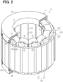
- FIG. 2 shows a part of the resin molded portion 50 in cross section.
- the stator core 20 has a plurality of split cores 21 arranged in an annular shape along a circumferential direction of the stator 11. For example, twelve split cores 21 are provided.
- the stator core 20 has, for example, twelve split cores 21.
- Each split core 21 is made of, for example, a magnetic metal material.
- a circumferential direction of the stator 11, a radial direction of the stator 11, and an axial direction of the stator 11 may be simply referred to as the "circumferential direction,” the "radial direction,” and the "axial direction,” respectively.
- Each split core 21 has a core back 22 and teeth 23 extending in the radial direction from the core back 22.
- the multiple split cores 21 are arranged in the circumferential direction such that the core backs 22 as a whole form an annular shape.
- Each of the teeth 23 extends in the radial direction.
- the teeth 23 protrude, for example, radially inward from an inner surface of the core back 22.
- the tips of the teeth 23 face an axis L1 of the stator 11.
- the base ends of the teeth 23 are the radially outer ends of the teeth 23.
- each split core 21 is formed of a plurality of core sheets 24 stacked in the axial direction.
- Each core sheet 24 is made of, for example, an electromagnetic steel plate.
- the core sheets 24 are fixed to one another by, for example, adhesion.
- each core back 22 of the split cores 21 are arranged in an annular shape along the circumferential direction.
- Each core back 22 constitutes an annular yoke portion 25.
- Each core back 22 is in contact with the adjacent core backs 22 on both sides in the circumferential direction.
- a radially outer surface of each core back 22 forms an outer peripheral surface of a yoke portion 25.
- the outer peripheral surface of the yoke portion 25, i.e., a radially outer surface of each core back 22, is in contact with an inner peripheral surface of the housing 14.
- Each tooth 23 extends radially inward from the yoke portion 25.
- each core back 22 forms an axial end surface 25a of the yoke portion 25.
- the axial end surfaces of each core back 22 are located, for example, on the same plane perpendicular to the axis L1. That is, the axial end surfaces 25a on both axial sides of the yoke portion 25 are flat and perpendicular to the axis L1.
- Each split core 21 is provided with a bobbin 30.
- a plurality of bobbins 30 are provided corresponding to the plurality of split cores 21, respectively.
- the bobbin 30 has a tooth covering portion 31 that covers the tooth 23.
- the coil 40 is wound around each tooth covering portion 31. That is, the tooth covering portion 31 of the bobbin 30 is interposed between the split core 21 and the coil 40.
- the bobbin 30 provides electrical insulation between the split core 21 and the coil 40.
- Each of the split core 21, the bobbin 30, and the coil 40 constitutes a single integrated part.
- the bobbin 30 is made of an insulating material such as synthetic resin.
- the bobbin 30 may be made of a material such as epoxy resin.
- the bobbin 30 is, for example, molded to the split core 21. That is, it is formed integrally with the split core 21. This allows the bobbin 30 to be in close contact with the split core 21.
- the resin molded portion 50 collectively covers, for example, the multiple coils 40.
- the coil 40 has a first end 41 as one axial end and a second end 42 as the other axial end.
- the resin molded portion 50 has a first covering portion 51 that covers the first end 41 of the coil 40, and a second covering portion 52 that covers the second end 42 of the coil 40.
- the first covering portion 51 covers the axial outside of the first end 41 of the coil 40 and both radial sides of the first end 41.
- the second covering portion 52 covers the axially outer side of the second end 42 of the coil 40 and both radially opposite sides of the second end 42.
- the resin molded portion 50 has a connecting portion 53 that passes between the teeth 23 adjacent to each other in the circumferential direction and connects the first covering portion 51 and the second covering portion 52.
- the connecting portions 53 are filled between each of the teeth 23.
- the first covering portion 51 and the second covering portion 52 are connected to each other by a plurality of connecting portions 53.
- the resin molded portion 50 is formed of, for example, a resin having a higher thermal conductivity than the bobbin 30.
- the resin molded portion 50 may be made of, for example, a material obtained by mixing alumina powder with epoxy resin or unsaturated polyester resin.
- the thermal conductivity of the bobbin 30 is set to, for example, 1.0 (W/m ⁇ K).
- the thermal conductivity of the resin molded portion 50 is preferably set to, for example, 2.0 (W/m ⁇ K) or more.
- the resin molded portion 50 has a structure with a large spring constant.
- the spring constant of the resin molded portion 50 is large, it is possible to keep the volume of the resin molded portion 50 necessary for suppressing the buckling of the yoke portion 25 small. As a result, the weight of the resin molded portion 50 can be reduced.
- each of the first covering portion 51 and the second covering portion 52 has an abutting part 54 that abuts against the axial end surface 25a of the yoke portion 25.
- the abutting part 54 of the first covering portion 51 abuts in the axial direction against the axial end surface 25a on one axial side.
- the abutting part 54 of the second covering portion 52 abuts in the axial direction against the axial end surface 25a on the other axial side. That is, the abutting parts 54 of the first covering portion 51 and the second covering portion 52 are provided so as to sandwich the yoke portion 25 in the axial direction.
- the abutting part 54 has a continuous annular shape along the circumferential direction.
- the abutting part 54 contacts each axial end surface 25a over the entire circumferential direction of the yoke portion 25. That is, as shown in FIG. 4 , the abutting part 54 contacts the axial end surface 25a at a boundary portion 22x where the core backs 22 adjacent in the circumferential direction are in contact with each other. Further, the abutting part 54 contacts the axial end surface 25a at the circumferential center portion 22y of each core back 22.
- the yoke portion 25 of the stator core 20 receives a radially inward force from the housing 14.
- the yoke portion 25 receives a radially inward force from the housing 14 more significantly.
- a force is generated in each of the core backs 22 constituting the yoke portion 25 in a direction in which they approach each other in the circumferential direction. Therefore, when no measures are taken, there is a risk that the core sheet 24 in each core back 22 constituting the yoke portion 25 may buckle due to stress during shrink fitting, for example.
- the abutting part 54 of the resin molded portion 50 abuts against the axial end surface 25a of the yoke portion 25.
- the abutting part 54 presses the axial end surface 25a of the yoke portion 25, thereby suppressing buckling of the portion of the core sheet 24 that constitutes the core back 22.
- the force that tends to buckle the yoke portion 25 acts in a direction expanding to both sides in the axial direction, and this force is received by each of the abutting part 54 of the first covering portion 51 and the second covering portion 52.
- the first covering portion 51 and the second covering portion 52 are connected by the connecting portion 53, the force exerted by the yoke portion 25 to buckle can be preferably received by each abutting part 54 of the first covering portion 51 and the second covering portion 52.
- the rotor 12 rotates due to interaction with a rotating magnetic field generated in the stator 11 by energizing each coil 40.
- the coil 40 generates heat by energizing.
- a part of the heat of the coil 40 is dissipated to the outside via the resin molded portion 50.
- An example of the heat dissipation path is a heat dissipation path that transmits from the coil 40 through the resin molded portion 50 to the stator core 20.
- the resin molded portion 50 from a material having a higher thermal conductivity than the bobbin 30, it is possible to further improve heat dissipation properties.
- the abutting part 54 suppresses buckling of the core sheets 24, crimping for fixing the core sheets 24 to each other is not required, or the number of crimping points can be minimized. This makes it possible to reduce iron loss caused by crimping in the flow of magnetic flux inside the core sheet 24. As a result, this can contribute to increasing the output of the rotating electric machine 10.
- the abutting part 54 prevents the core sheet 24 from buckling, no adhesive is required to fix the core sheets 24 to each other. In other words, it is possible to have a structure in which the core sheets 24 are not fixed to each other. In this case, since no adhesive is used to bond the core sheets 24 together, it is possible to achieve a configuration with excellent heat resistance.
- the stator core 20 is made up of a plurality of split cores 21 arranged in the circumferential direction.
- Each of the multiple split cores 21 has the core back 22 that constitutes the yoke portion 25 and the teeth 23 extending from the core back 22.
- the yoke portion 25 is formed by the core backs 22 of the respective split cores 21. Therefore, each divided core back 22 is more likely to buckle due to the force received from the housing 14. Therefore, the buckling suppression effect of the abutting part 54 can be more significantly obtained.
- the abutting part 54 abuts against the axial end surface 25a of the yoke portion 25 over the entire circumferential direction. According to this configuration, in each core back 22, it is possible for the abutting part 54 to press both the boundary portion 22x and the circumferential center portion 22y, where buckling is likely to occur. Therefore, the abutting part 54 can more effectively suppress buckling of the yoke portion 25.
- the resin molded portion 50 covers the coil 40.
- the coil 40 has the first end 41 as one axial end and the second end 42 as the other axial end.
- the resin molded portion 50 has the first covering portion 51 covering the first end 41 of the coil 40, the second covering portion 52 covering the second end 42 of the coil 40, and the connecting portion 53 passing between circumferentially adjacent coils 40 and connecting the first covering portion 51 and the second covering portion 52.
- the abutting part 54 is included in each of the first covering portion 51 and the second covering portion 52. According to this configuration, the abutting part 54 of the first covering portion 51 and the abutting part 54 of the second covering portion 52 sandwich the yoke portion 25 in the axial direction. Further, the first covering portion 51 and the second covering portion 52 are connected to each other by the connecting portion 53. Therefore, the abutting parts 54 can more effectively suppress buckling of the yoke portion 25 on both axial sides of the yoke portion 25.
- the stator core 20 has a plurality of teeth 23 arranged in the circumferential direction.
- a plurality of coils 40 are provided corresponding to the plurality of teeth 23, respectively.
- the resin molded portion 50 covers the multiple coils 40 collectively. It is possible to improve the heat dissipation properties of the coil 40 via the resin molded portion 50. As a result, this can contribute to increasing the output of the rotating electric machine 10.
- the resin molded portion 50 is made of a material having a higher thermal conductivity than the bobbin 30. It is possible to further improve the heat dissipation properties of the coil 40 via the resin molded portion 50.
- the abutting part 54 may be configured to partially contact the axial end surface 25a of the yoke portion 25 in the circumferential direction.
- the volume of the resin molded portion 50 can be reduced. As a result, this can contribute to reducing the weight of the stator 11.
- the abutting parts 54 contact the axial end surfaces 25a at the boundary portions 22x where the core backs 22 adjacent in the circumferential direction are in contact with each other. According to such a configuration, it is possible to reduce the weight of the resin molded portion 50 while suppressing buckling of the boundary portions 22x of the core back 22, which is prone to buckling.
- the resin molded portion 50 including the abutting parts 54 may be configured to be scattered in the circumferential direction. Also, as shown in FIG. 5 , the resin molded portion 50 may not cover the axially outer side of the coil 40.
- the abutting parts 54 contact the axial end surface 25a at the circumferential center portion 22y of each core back 22.
- the resin molded portion 50 may be formed of a material having the same thermal conductivity as the bobbin 30 or a material having a lower thermal conductivity than the bobbin 30.
- Each core sheet 24 may be fixed to each other by, for example, crimping. Additionally, each core sheet 24 may be fixed to each other by, for example, caulking or adhesive. Additionally, each core sheet 24 may be fixed to one another by welding, such as laser welding.
- An adhesive may be used to temporarily fix the core sheets 24 together until the resin molded portion 50 is formed.
- the adhesive strength is sufficient if it is strong enough to form the resin molded portion 50, so there are few restrictions on the selection of the adhesive material.
- the stator core 20 does not need to be formed by the plurality of split cores 21, and may be formed as an integrated part. Even in this configuration, the abutting part 54 can suppress buckling of the portion of the core sheet 24 that constitutes the yoke portion 25.
- the bobbin 30 is molded to the stator core 20.
- the present disclosure is not limited to this configuration.
- a configuration in which a separately manufactured bobbin is attached to the stator core 20 may be used.
- the number of split cores 21 and the number of teeth 23 are not limited to those in the above embodiment and may be changed as appropriate depending on the configuration.
- the rotating electric machine 10 in the above embodiment is an inner rotor type rotating electric machine in which the rotor 12 is arranged on the inner side of the stator 11, but it may also be applied to, for example, an outer rotor type rotating electric machine in which the rotor is arranged on the outer side of the stator.
Landscapes
- Engineering & Computer Science (AREA)
- Power Engineering (AREA)
- Iron Core Of Rotating Electric Machines (AREA)
- Insulation, Fastening Of Motor, Generator Windings (AREA)
Abstract
Description
- This application is based on
Japanese Application No. 2022-080006 filed on May 16, 2022 - The present disclosure relates to a stator and a rotating electric machine.
- For example, the stator described in
Patent Document 1 includes a stator core formed of a plurality of core sheets stacked in an axial direction. The stator core has an annular yoke portion and teeth extending radially inward from the yoke portion. Coils are wound around the teeth. The stator core is accommodated in a housing with an outer peripheral surface of the yoke portion in contact with an inner peripheral surface of the housing. - Patent Document 1:
JP 2010-288424 A - In the above-described stator, for example, there is a risk that a portion of the core sheet that constitutes the yoke portion may buckle due to a force that the yoke portion receives from the housing.
- An object of the present disclosure is to provide a stator and a rotating electric machine capable of suppressing buckling of a core sheet.
- In a first aspect of the present disclosure, a stator is formed of a plurality of core sheets stacked in an axial direction, and includes a stator core having an annular yoke portion and teeth extending inward from the yoke portion, a bobbin covering the teeth, a coil wound around the bobbin, and a pressing member having an abutting part abutting an axial end surface of the yoke portion.
- In a second aspect of the present disclosure, a rotating electric machine includes a stator and a rotor facing the stator, and the stator is formed of a plurality of core sheets stacked in an axial direction, and includes a stator core having an annular yoke portion and teeth extending inward from the yoke portion, a bobbin covering the teeth, a coil wound around the bobbin, and a pressing member having an abutting part abutting an axial end surface of the yoke portion.
- According to the above-described stator and rotating electric machine, the pressing member having the abutting part that abuts against the axial end surface of the yoke portion makes it possible to suppress buckling of a portion of the core sheet that constitutes the yoke portion.
- The above and other objects, features and advantages of the present disclosure will become more apparent from the following detailed description made with reference to the accompanying drawings.
- In the drawings,
-
FIG. 1 is a schematic diagram of a rotating electric machine according to an embodiment; -
FIG. 2 is a perspective view showing a stator of the same embodiment, partially in section; -
FIG. 3 is a schematic cross-sectional view of a stator of the same embodiment; -
FIG. 4 is a schematic side view of a stator of the same embodiment; -
FIG. 5 is a schematic side view of a stator according to a modified example; and -
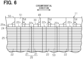
FIG. 6 is a schematic side view of a stator according to a modified example. - Hereinafter, an embodiment of a stator and a rotating electric machine will be described with reference to the drawings. In the drawings, a part of the configuration may be exaggerated or simplified for convenience of description. Furthermore, the dimensional ratios of each component may differ between the drawings.
- As shown in
FIG. 1 , a rotatingelectric machine 10 includes astator 11 and arotor 12 facing thestator 11. Thestator 11 has an annular shape. Therotor 12 is disposed inside thestator 11. Therotor 12 has a rotatingshaft 13. Therotor 12 faces thestator 11 in a radial direction. Thestator 11 is accommodated in acylindrical housing 14. Thestator 11 is accommodated in thehousing 14 by, for example, shrink fitting. - As shown in
FIGS. 1 and2 , thestator 11 includes astator core 20, abobbin 30, acoil 40, and a resin moldedportion 50 serving as a pressing member. In addition,FIG. 2 shows a part of the resin moldedportion 50 in cross section. - The
stator core 20 has a plurality ofsplit cores 21 arranged in an annular shape along a circumferential direction of thestator 11. For example, twelvesplit cores 21 are provided. Thestator core 20 has, for example, twelvesplit cores 21. Each splitcore 21 is made of, for example, a magnetic metal material. In the following description, a circumferential direction of thestator 11, a radial direction of thestator 11, and an axial direction of thestator 11 may be simply referred to as the "circumferential direction," the "radial direction," and the "axial direction," respectively. - Each
split core 21 has acore back 22 andteeth 23 extending in the radial direction from thecore back 22. Themultiple split cores 21 are arranged in the circumferential direction such that thecore backs 22 as a whole form an annular shape. Each of theteeth 23 extends in the radial direction. - In each split
core 21, theteeth 23 protrude, for example, radially inward from an inner surface of thecore back 22. The tips of theteeth 23 face an axis L1 of thestator 11. The base ends of theteeth 23 are the radially outer ends of theteeth 23. - As shown in
FIG. 3 , each splitcore 21 is formed of a plurality ofcore sheets 24 stacked in the axial direction. Eachcore sheet 24 is made of, for example, an electromagnetic steel plate. Thecore sheets 24 are fixed to one another by, for example, adhesion. - As shown in
Figs. 1 and2 , in a state in which thesplit cores 21 are arranged in an annular shape in the circumferential direction, thecore backs 22 of thesplit cores 21 are arranged in an annular shape along the circumferential direction. Eachcore back 22 constitutes anannular yoke portion 25. Eachcore back 22 is in contact with theadjacent core backs 22 on both sides in the circumferential direction. A radially outer surface of eachcore back 22 forms an outer peripheral surface of ayoke portion 25. The outer peripheral surface of theyoke portion 25, i.e., a radially outer surface of eachcore back 22, is in contact with an inner peripheral surface of thehousing 14. Eachtooth 23 extends radially inward from theyoke portion 25. - As shown in
FIG. 3 , on each of both axial sides of thestator core 20, the axial end surface of eachcore back 22 forms anaxial end surface 25a of theyoke portion 25. The axial end surfaces of eachcore back 22 are located, for example, on the same plane perpendicular to the axis L1. That is, theaxial end surfaces 25a on both axial sides of theyoke portion 25 are flat and perpendicular to the axis L1. - Each split
core 21 is provided with abobbin 30. For example, a plurality ofbobbins 30 are provided corresponding to the plurality ofsplit cores 21, respectively. Thebobbin 30 has atooth covering portion 31 that covers thetooth 23. Thecoil 40 is wound around eachtooth covering portion 31. That is, thetooth covering portion 31 of thebobbin 30 is interposed between thesplit core 21 and thecoil 40. As a result, thebobbin 30 provides electrical insulation between thesplit core 21 and thecoil 40. Each of thesplit core 21, thebobbin 30, and thecoil 40 constitutes a single integrated part. - The
bobbin 30 is made of an insulating material such as synthetic resin. Thebobbin 30 may be made of a material such as epoxy resin. Thebobbin 30 is, for example, molded to thesplit core 21. That is, it is formed integrally with thesplit core 21. This allows thebobbin 30 to be in close contact with thesplit core 21. - In addition, as a configuration different from that of the present embodiment, for example, when a bobbin manufactured separately from the
split core 21 is later attached to thesplit core 21, there is a concern that a large gap may occur between thesplit core 21 and the bobbin. In this regard, by molding thebobbin 30 to thesplit core 21 as in the present embodiment, it is possible to eliminate the gap between thesplit core 21 and thebobbin 30 or to make the gap extremely small. - As shown in
FIG. 2 , the resin moldedportion 50 collectively covers, for example, the multiple coils 40. As shown inFIG. 3 , thecoil 40 has afirst end 41 as one axial end and asecond end 42 as the other axial end. The resin moldedportion 50 has afirst covering portion 51 that covers thefirst end 41 of thecoil 40, and asecond covering portion 52 that covers thesecond end 42 of thecoil 40. Thefirst covering portion 51 covers the axial outside of thefirst end 41 of thecoil 40 and both radial sides of thefirst end 41. Thesecond covering portion 52 covers the axially outer side of thesecond end 42 of thecoil 40 and both radially opposite sides of thesecond end 42. - As shown in
FIGS. 1 and2 , the resin moldedportion 50 has a connectingportion 53 that passes between theteeth 23 adjacent to each other in the circumferential direction and connects thefirst covering portion 51 and thesecond covering portion 52. The connectingportions 53 are filled between each of theteeth 23. Thefirst covering portion 51 and thesecond covering portion 52 are connected to each other by a plurality of connectingportions 53. - In the
stator 11, for example, an integral part including thesplit core 21, thebobbin 30, and thecoil 40 is arranged in an annular shape. Thereafter, eachcoil 40 is electrically connected by, for example, a bus bar. Thereafter, for example, the resin moldedportion 50 is molded so as to collectively cover each of thecoils 40, each of thebobbins 30, the bus bars, and the like. - The resin molded
portion 50 is formed of, for example, a resin having a higher thermal conductivity than thebobbin 30. The resin moldedportion 50 may be made of, for example, a material obtained by mixing alumina powder with epoxy resin or unsaturated polyester resin. The thermal conductivity of thebobbin 30 is set to, for example, 1.0 (W/m·K). In contrast, the thermal conductivity of the resin moldedportion 50 is preferably set to, for example, 2.0 (W/m·K) or more. - Moreover, it is preferable that the resin molded
portion 50 has a structure with a large spring constant. When the spring constant of the resin moldedportion 50 is large, it is possible to keep the volume of the resin moldedportion 50 necessary for suppressing the buckling of theyoke portion 25 small. As a result, the weight of the resin moldedportion 50 can be reduced. - As shown in
FIGS. 2 and3 , each of thefirst covering portion 51 and thesecond covering portion 52 has anabutting part 54 that abuts against theaxial end surface 25a of theyoke portion 25. The abuttingpart 54 of thefirst covering portion 51 abuts in the axial direction against theaxial end surface 25a on one axial side. The abuttingpart 54 of thesecond covering portion 52 abuts in the axial direction against theaxial end surface 25a on the other axial side. That is, the abuttingparts 54 of thefirst covering portion 51 and thesecond covering portion 52 are provided so as to sandwich theyoke portion 25 in the axial direction. - In the present embodiment, the abutting
part 54 has a continuous annular shape along the circumferential direction. The abuttingpart 54 contacts eachaxial end surface 25a over the entire circumferential direction of theyoke portion 25. That is, as shown inFIG. 4 , the abuttingpart 54 contacts theaxial end surface 25a at aboundary portion 22x where the core backs 22 adjacent in the circumferential direction are in contact with each other. Further, the abuttingpart 54 contacts theaxial end surface 25a at the circumferential center portion 22y of each core back 22. - The operation of the present embodiment will be described.
- The
yoke portion 25 of thestator core 20 receives a radially inward force from thehousing 14. When thestator core 20 is assembled to thehousing 14 by shrink fitting, theyoke portion 25 receives a radially inward force from thehousing 14 more significantly. Then, a force is generated in each of the core backs 22 constituting theyoke portion 25 in a direction in which they approach each other in the circumferential direction. Therefore, when no measures are taken, there is a risk that thecore sheet 24 in each core back 22 constituting theyoke portion 25 may buckle due to stress during shrink fitting, for example. - Therefore, in the present embodiment, the abutting
part 54 of the resin moldedportion 50 abuts against theaxial end surface 25a of theyoke portion 25. As a result, when each core back 22 constituting theyoke portion 25 receives force from thehousing 14, the abuttingpart 54 presses theaxial end surface 25a of theyoke portion 25, thereby suppressing buckling of the portion of thecore sheet 24 that constitutes the core back 22. In addition, the force that tends to buckle theyoke portion 25 acts in a direction expanding to both sides in the axial direction, and this force is received by each of theabutting part 54 of thefirst covering portion 51 and thesecond covering portion 52. Here, since thefirst covering portion 51 and thesecond covering portion 52 are connected by the connectingportion 53, the force exerted by theyoke portion 25 to buckle can be preferably received by each abuttingpart 54 of thefirst covering portion 51 and thesecond covering portion 52. - Furthermore, the
rotor 12 rotates due to interaction with a rotating magnetic field generated in thestator 11 by energizing eachcoil 40. At this time, thecoil 40 generates heat by energizing. A part of the heat of thecoil 40 is dissipated to the outside via the resin moldedportion 50. An example of the heat dissipation path is a heat dissipation path that transmits from thecoil 40 through the resin moldedportion 50 to thestator core 20. Furthermore, by forming the resin moldedportion 50 from a material having a higher thermal conductivity than thebobbin 30, it is possible to further improve heat dissipation properties. - The effects of the present embodiment will be described.
- (1) The
stator 11 includes the resin moldedportion 50 serving as a pressing member having the abuttingpart 54 that abuts against theaxial end surface 25a of theyoke portion 25. According to this configuration, the resin moldedportion 50 having the abuttingpart 54 that abuts against theaxial end surface 25a of theyoke portion 25 makes it possible to suppress buckling of the portion of thecore sheet 24 that constitutes theyoke portion 25. - In addition, since the abutting
part 54 suppresses buckling of thecore sheets 24, crimping for fixing thecore sheets 24 to each other is not required, or the number of crimping points can be minimized. This makes it possible to reduce iron loss caused by crimping in the flow of magnetic flux inside thecore sheet 24. As a result, this can contribute to increasing the output of the rotatingelectric machine 10. - Furthermore, since the abutting
part 54 prevents thecore sheet 24 from buckling, no adhesive is required to fix thecore sheets 24 to each other. In other words, it is possible to have a structure in which thecore sheets 24 are not fixed to each other. In this case, since no adhesive is used to bond thecore sheets 24 together, it is possible to achieve a configuration with excellent heat resistance. - (2) The
stator core 20 is made up of a plurality ofsplit cores 21 arranged in the circumferential direction. Each of themultiple split cores 21 has the core back 22 that constitutes theyoke portion 25 and theteeth 23 extending from the core back 22. According to this configuration, theyoke portion 25 is formed by the core backs 22 of therespective split cores 21. Therefore, each divided core back 22 is more likely to buckle due to the force received from thehousing 14. Therefore, the buckling suppression effect of theabutting part 54 can be more significantly obtained. - (3) The abutting
part 54 abuts against theaxial end surface 25a of theyoke portion 25 over the entire circumferential direction. According to this configuration, in each core back 22, it is possible for theabutting part 54 to press both theboundary portion 22x and the circumferential center portion 22y, where buckling is likely to occur. Therefore, the abuttingpart 54 can more effectively suppress buckling of theyoke portion 25. - (4) The resin molded
portion 50 covers thecoil 40. Thecoil 40 has thefirst end 41 as one axial end and thesecond end 42 as the other axial end. The resin moldedportion 50 has thefirst covering portion 51 covering thefirst end 41 of thecoil 40, thesecond covering portion 52 covering thesecond end 42 of thecoil 40, and the connectingportion 53 passing between circumferentiallyadjacent coils 40 and connecting thefirst covering portion 51 and thesecond covering portion 52. The abuttingpart 54 is included in each of thefirst covering portion 51 and thesecond covering portion 52. According to this configuration, the abuttingpart 54 of thefirst covering portion 51 and theabutting part 54 of thesecond covering portion 52 sandwich theyoke portion 25 in the axial direction. Further, thefirst covering portion 51 and thesecond covering portion 52 are connected to each other by the connectingportion 53. Therefore, the abuttingparts 54 can more effectively suppress buckling of theyoke portion 25 on both axial sides of theyoke portion 25. - (5) The
stator core 20 has a plurality ofteeth 23 arranged in the circumferential direction. A plurality ofcoils 40 are provided corresponding to the plurality ofteeth 23, respectively. The resin moldedportion 50 covers themultiple coils 40 collectively. It is possible to improve the heat dissipation properties of thecoil 40 via the resin moldedportion 50. As a result, this can contribute to increasing the output of the rotatingelectric machine 10. - (6) The resin molded
portion 50 is made of a material having a higher thermal conductivity than thebobbin 30. It is possible to further improve the heat dissipation properties of thecoil 40 via the resin moldedportion 50. - The above-described embodiments may be modified as follows. The above-described embodiments and the following modifications can be implemented in combination with one another as long as there is no technical contradiction.
- For example, as shown in
FIG. 5 orFIG. 6 , the abuttingpart 54 may be configured to partially contact theaxial end surface 25a of theyoke portion 25 in the circumferential direction. With this configuration, the volume of the resin moldedportion 50 can be reduced. As a result, this can contribute to reducing the weight of thestator 11. - In the configuration shown in
FIG. 5 , the abuttingparts 54 contact theaxial end surfaces 25a at theboundary portions 22x where the core backs 22 adjacent in the circumferential direction are in contact with each other. According to such a configuration, it is possible to reduce the weight of the resin moldedportion 50 while suppressing buckling of theboundary portions 22x of the core back 22, which is prone to buckling. In this case, the resin moldedportion 50 including the abuttingparts 54 may be configured to be scattered in the circumferential direction. Also, as shown inFIG. 5 , the resin moldedportion 50 may not cover the axially outer side of thecoil 40. - In the configuration shown in
FIG. 6 , the abuttingparts 54 contact theaxial end surface 25a at the circumferential center portion 22y of each core back 22. With this configuration, it is possible to reduce the weight of the resin moldedportion 50 while suppressing buckling of the circumferential center portion 22y of the core back 22, which is prone to buckling. - The resin molded
portion 50 may be formed of a material having the same thermal conductivity as thebobbin 30 or a material having a lower thermal conductivity than thebobbin 30. - Each
core sheet 24 may be fixed to each other by, for example, crimping. Additionally, eachcore sheet 24 may be fixed to each other by, for example, caulking or adhesive. Additionally, eachcore sheet 24 may be fixed to one another by welding, such as laser welding. - An adhesive may be used to temporarily fix the
core sheets 24 together until the resin moldedportion 50 is formed. In this case, the adhesive strength is sufficient if it is strong enough to form the resin moldedportion 50, so there are few restrictions on the selection of the adhesive material. - The
stator core 20 does not need to be formed by the plurality ofsplit cores 21, and may be formed as an integrated part. Even in this configuration, the abuttingpart 54 can suppress buckling of the portion of thecore sheet 24 that constitutes theyoke portion 25. - In the above embodiment, the
bobbin 30 is molded to thestator core 20. However, the present disclosure is not limited to this configuration. For example, a configuration in which a separately manufactured bobbin is attached to thestator core 20 may be used. - The number of
split cores 21 and the number ofteeth 23 are not limited to those in the above embodiment and may be changed as appropriate depending on the configuration. - The rotating
electric machine 10 in the above embodiment is an inner rotor type rotating electric machine in which therotor 12 is arranged on the inner side of thestator 11, but it may also be applied to, for example, an outer rotor type rotating electric machine in which the rotor is arranged on the outer side of the stator. - Although the present disclosure has been described in accordance with the examples, it is understood that the present disclosure is not limited to such examples or structures. The present disclosure encompasses various modifications and variations within the scope of equivalents. In addition, while the various combinations and configurations, which are preferred, other combinations and configurations, including more, less or only a single element, are also within the spirit and scope of the present disclosure.
- The features of the present disclosure are as follows.
- [1] A stator including: a stator core (20) formed of a plurality of core sheets (24) stacked in an axial direction, the stator core having an annular yoke portion (25) and teeth (23) extending inward from the yoke portion; a bobbin (30) covering the teeth; a coil (40) wound around the bobbin; and a pressing member (50) having an abutting part (54) abutting against an axial end surface (25a) of the yoke portion.
- [2] The stator described in the above-mentioned [1], wherein the stator core is composed of a plurality of split cores (21) arranged along a circumferential direction, and each of the plurality of split cores has a core back (22) constituting the yoke portion and the teeth extending from the core back.
- [3] The stator according to the above-mentioned [1] or [2], wherein the abutting part abuts against the axial end surface over the entire circumferential direction of the yoke portion.
- [4] The stator according to the above-mentioned [2], wherein the abutting part abuts partially in the circumferential direction of the yoke portion against the axial end surface.
- [5] The stator according to the above-mentioned [4], wherein the abutting part contacts the axial end surface at a boundary portion (22x) where the core backs adjacent in the circumferential direction contact each other.
- [6] The stator according to the above-mentioned [4], wherein the abutting part contacts the axial end surface at a circumferential center portion (22y) of the core back.
- [7] The stator described in any one of the above-mentioned [1] to [6], wherein the pressing member is a resin molded portion (50) covering the coil, the coil has one axial end (41) and the other axial end (42), the resin molded portion has a first covering portion (51) covering the one axial end of the coil, a second covering portion (52) covering the other axial end of the coil, and a connecting portion (53) connecting the first covering portion and the second covering portion, and the abutting part is included in each of the first covering portion and the second covering portion.
- [8] The stator described in the above-mentioned [7], the stator core has a plurality of teeth arranged along the circumferential direction, a plurality of coils are provided corresponding to each of the teeth, and the resin molded portion covers the plurality of coils collectively.
- [9] The stator according to the above-mentioned [7] or [8], wherein the resin molded portion is formed of a material having a higher thermal conductivity than the bobbin.
- [10] A rotating electric machine (10) includes a stator (11) and a rotor (12) facing the stator, and the stator is formed of a plurality of core sheets (24) stacked in an axial direction, and includes a stator core (20) having an annular yoke portion (25) and teeth (23) extending inward from the yoke portion, a bobbin (30) covering the teeth, a coil (40) wound around the bobbin, and a pressing member (50) having an abutting part (54) abutting an axial end surface (25a) of the yoke portion.
Claims (10)
- A stator, comprising:a stator core (20) formed of a plurality of core sheets (24) stacked in an axial direction, and having an annular yoke portion (25) and teeth (23) extending from the yoke portion to an inner peripheral side;a bobbin (30) configured to cover the teeth;a coil (40) wound around the bobbin; anda pressing member (50) having an abutting part (54) that contacts an axial end surface (25a) of the yoke portion.
- The stator according to claim 1, whereinthe stator core is composed of a plurality of split cores (21) arranged along a circumferential direction, andeach of the plurality of split cores has a core back (22) that constitutes the yoke portion, and the teeth extending from the core back.
- The stator according to claim 1 or 2, wherein
the abutting part abuts against the axial end surface over the entire circumferential direction of the yoke portion. - The stator according to claim 2, wherein
the abutting part abuts partially in the circumferential direction of the yoke portion on the axial end surface. - The stator according to claim 4, wherein
the abutting part contacts the axial end surface at a boundary portion (22x) where the core backs adjacent in the circumferential direction are in contact with each other. - The stator according to claim 4, wherein
the abutting part contacts the axial end surface at a circumferential center portion (22y) of the core back. - The stator according to claim 1, whereinthe pressing member is a resin molded portion (50) that covers the coil,the coil has one axial end (41) and another axial end (42),the resin molded portion has a first covering portion (51) covering one axial end portion of the coil, a second covering portion (52) covering the other axial end portion of the coil, and a connecting portion (53) connecting the first covering portion and the second covering portion, andthe abutting part is included in each of the first covering portion and the second covering portion.
- The stator according to claim 7, whereinthe stator core has a plurality of the teeth arranged along a circumferential direction,a plurality of coils are provided corresponding to the plurality of teeth, respectively, andthe resin molded portion collectively covers the plurality of coils.
- The stator according to claim 7 or 8, wherein
the resin molded portion is made of a material having a higher thermal conductivity than the bobbin. - A rotating electric machine (10) comprising:a stator (11); anda rotor (12) facing the stator, whereinthe stator includes:a stator core (20) formed of a plurality of core sheets (24) stacked in an axial direction, and having an annular yoke portion (25) and teeth (23) extending from the yoke portion to an inner peripheral side;a bobbin (30) configured to cover the teeth;a coil (40) wound around the bobbin; anda pressing member (50) having an abutting part (54) that contacts an axial end surface (25a) of the yoke portion.
Applications Claiming Priority (2)
| Application Number | Priority Date | Filing Date | Title |
|---|---|---|---|
| JP2022080006A JP2023168728A (en) | 2022-05-16 | 2022-05-16 | Stator and rotary electric machine |
| PCT/JP2023/018169 WO2023224014A1 (en) | 2022-05-16 | 2023-05-15 | Stator and rotating electric machine |
Publications (2)
| Publication Number | Publication Date |
|---|---|
| EP4528988A1 true EP4528988A1 (en) | 2025-03-26 |
| EP4528988A4 EP4528988A4 (en) | 2025-09-17 |
Family
ID=88835500
Family Applications (1)
| Application Number | Title | Priority Date | Filing Date |
|---|---|---|---|
| EP23807616.0A Pending EP4528988A4 (en) | 2022-05-16 | 2023-05-15 | STATOR AND ELECTRIC LATHE |
Country Status (5)
| Country | Link |
|---|---|
| US (1) | US20250070610A1 (en) |
| EP (1) | EP4528988A4 (en) |
| JP (1) | JP2023168728A (en) |
| CN (1) | CN119183631A (en) |
| WO (1) | WO2023224014A1 (en) |
Families Citing this family (1)
| Publication number | Priority date | Publication date | Assignee | Title |
|---|---|---|---|---|
| JP7573798B1 (en) * | 2024-04-24 | 2024-10-25 | 三菱電機株式会社 | Stator and motor |
Family Cites Families (8)
| Publication number | Priority date | Publication date | Assignee | Title |
|---|---|---|---|---|
| JPH05336711A (en) * | 1992-05-28 | 1993-12-17 | Yaskawa Electric Corp | Method for manufacturing stator of electric motor |
| JP2000341889A (en) * | 1999-05-25 | 2000-12-08 | Hitachi Ltd | Rotating machine core, method of manufacturing the same, core element and rotating machine |
| JP3780164B2 (en) * | 2000-11-09 | 2006-05-31 | 株式会社日立産機システム | Rotating electric machine |
| JP5819037B2 (en) | 2009-06-15 | 2015-11-18 | 株式会社デンソー | Rotating electric machine stator and rotating electric machine |
| WO2017145332A1 (en) * | 2016-02-25 | 2017-08-31 | 株式会社安川電機 | Rotary electric machine and method for manufacturing rotary electric machine |
| US10256688B1 (en) * | 2017-10-10 | 2019-04-09 | Zero E Technologies, Llc | Electric machine rotor cooling systems and methods |
| JP2019080429A (en) * | 2017-10-24 | 2019-05-23 | 日立オートモティブシステムズ株式会社 | Rotary electric machine, method of manufacturing the rotary electric machine, and stator |
| CN112136264A (en) * | 2019-03-13 | 2020-12-25 | 株式会社Top | Rotating machines and insulators |
-
2022
- 2022-05-16 JP JP2022080006A patent/JP2023168728A/en active Pending
-
2023
- 2023-05-15 WO PCT/JP2023/018169 patent/WO2023224014A1/en not_active Ceased
- 2023-05-15 EP EP23807616.0A patent/EP4528988A4/en active Pending
- 2023-05-15 CN CN202380040004.XA patent/CN119183631A/en active Pending
-
2024
- 2024-11-14 US US18/948,095 patent/US20250070610A1/en active Pending
Also Published As
| Publication number | Publication date |
|---|---|
| WO2023224014A1 (en) | 2023-11-23 |
| JP2023168728A (en) | 2023-11-29 |
| US20250070610A1 (en) | 2025-02-27 |
| CN119183631A (en) | 2024-12-24 |
| EP4528988A4 (en) | 2025-09-17 |
Similar Documents
| Publication | Publication Date | Title |
|---|---|---|
| EP1146624B1 (en) | Stator core of vehicle rotary electric machine and method of manufacturing the same | |
| US5508577A (en) | Electric rotating machine | |
| JP7209264B2 (en) | Insulators and stators and motors equipped with them | |
| JP2009142031A (en) | Stator for rotating electrical machine | |
| JP2008035616A (en) | motor | |
| CN110492630A (en) | rotating electrical machine | |
| US20250070610A1 (en) | Stator and rotating electric machine | |
| CN110277856A (en) | Stator of a rotating electrical machine | |
| JP7211883B2 (en) | stator and motor | |
| JP2011147200A (en) | Motor armature | |
| US20140210303A1 (en) | Bobbin and rotary electric machine | |
| JP7289102B2 (en) | Insulators and stators and motors equipped with them | |
| CN116762260A (en) | stator | |
| EP1836760B1 (en) | Rotating electric machine | |
| JP7746911B2 (en) | Stator and method for manufacturing the same | |
| JP7643950B2 (en) | Rotating Electric Machine | |
| JP7632209B2 (en) | Armature and motor | |
| JP2008048592A (en) | Stator | |
| JP7596974B2 (en) | Armature manufacturing apparatus and armature manufacturing method | |
| JP2020036437A (en) | Polyphase claw pole motor | |
| JP7463995B2 (en) | Armature and method for manufacturing the same | |
| CN111585364B9 (en) | Stator of rotating electric machine | |
| WO2024247427A1 (en) | Stator and electric motor provided with same | |
| JP2020054028A (en) | How to attach stator, motor and bus ring | |
| WO2019146450A1 (en) | Insulator, stator provided with same, and motor |
Legal Events
| Date | Code | Title | Description |
|---|---|---|---|
| STAA | Information on the status of an ep patent application or granted ep patent |
Free format text: STATUS: THE INTERNATIONAL PUBLICATION HAS BEEN MADE |
|
| PUAI | Public reference made under article 153(3) epc to a published international application that has entered the european phase |
Free format text: ORIGINAL CODE: 0009012 |
|
| STAA | Information on the status of an ep patent application or granted ep patent |
Free format text: STATUS: REQUEST FOR EXAMINATION WAS MADE |
|
| 17P | Request for examination filed |
Effective date: 20241010 |
|
| AK | Designated contracting states |
Kind code of ref document: A1 Designated state(s): AL AT BE BG CH CY CZ DE DK EE ES FI FR GB GR HR HU IE IS IT LI LT LU LV MC ME MK MT NL NO PL PT RO RS SE SI SK SM TR |
|
| DAV | Request for validation of the european patent (deleted) | ||
| DAX | Request for extension of the european patent (deleted) | ||
| STAA | Information on the status of an ep patent application or granted ep patent |
Free format text: STATUS: EXAMINATION IS IN PROGRESS |
|
| A4 | Supplementary search report drawn up and despatched |
Effective date: 20250818 |
|
| RIC1 | Information provided on ipc code assigned before grant |
Ipc: H02K 1/18 20060101AFI20250811BHEP Ipc: H02K 3/44 20060101ALI20250811BHEP Ipc: H02K 1/14 20060101ALI20250811BHEP Ipc: H02K 3/32 20060101ALI20250811BHEP Ipc: H02K 3/52 20060101ALI20250811BHEP |
|
| 17Q | First examination report despatched |
Effective date: 20250829 |