EP4528941A1 - Electrical contact terminal with a crimp portion and assembling method thereof - Google Patents
Electrical contact terminal with a crimp portion and assembling method thereof Download PDFInfo
- Publication number
- EP4528941A1 EP4528941A1 EP23198701.7A EP23198701A EP4528941A1 EP 4528941 A1 EP4528941 A1 EP 4528941A1 EP 23198701 A EP23198701 A EP 23198701A EP 4528941 A1 EP4528941 A1 EP 4528941A1
- Authority
- EP
- European Patent Office
- Prior art keywords
- wire
- crimp portion
- electrical
- contact terminal
- electrical contact
- Prior art date
- Legal status (The legal status is an assumption and is not a legal conclusion. Google has not performed a legal analysis and makes no representation as to the accuracy of the status listed.)
- Pending
Links
Images



Classifications
-
- H—ELECTRICITY
- H01—ELECTRIC ELEMENTS
- H01R—ELECTRICALLY-CONDUCTIVE CONNECTIONS; STRUCTURAL ASSOCIATIONS OF A PLURALITY OF MUTUALLY-INSULATED ELECTRICAL CONNECTING ELEMENTS; COUPLING DEVICES; CURRENT COLLECTORS
- H01R4/00—Electrically-conductive connections between two or more conductive members in direct contact, i.e. touching one another; Means for effecting or maintaining such contact; Electrically-conductive connections having two or more spaced connecting locations for conductors and using contact members penetrating insulation
- H01R4/10—Electrically-conductive connections between two or more conductive members in direct contact, i.e. touching one another; Means for effecting or maintaining such contact; Electrically-conductive connections having two or more spaced connecting locations for conductors and using contact members penetrating insulation effected solely by twisting, wrapping, bending, crimping, or other permanent deformation
- H01R4/18—Electrically-conductive connections between two or more conductive members in direct contact, i.e. touching one another; Means for effecting or maintaining such contact; Electrically-conductive connections having two or more spaced connecting locations for conductors and using contact members penetrating insulation effected solely by twisting, wrapping, bending, crimping, or other permanent deformation by crimping
- H01R4/183—Electrically-conductive connections between two or more conductive members in direct contact, i.e. touching one another; Means for effecting or maintaining such contact; Electrically-conductive connections having two or more spaced connecting locations for conductors and using contact members penetrating insulation effected solely by twisting, wrapping, bending, crimping, or other permanent deformation by crimping for cylindrical elongated bodies, e.g. cables having circular cross-section
-
- H—ELECTRICITY
- H01—ELECTRIC ELEMENTS
- H01R—ELECTRICALLY-CONDUCTIVE CONNECTIONS; STRUCTURAL ASSOCIATIONS OF A PLURALITY OF MUTUALLY-INSULATED ELECTRICAL CONNECTING ELEMENTS; COUPLING DEVICES; CURRENT COLLECTORS
- H01R4/00—Electrically-conductive connections between two or more conductive members in direct contact, i.e. touching one another; Means for effecting or maintaining such contact; Electrically-conductive connections having two or more spaced connecting locations for conductors and using contact members penetrating insulation
- H01R4/02—Soldered or welded connections
- H01R4/023—Soldered or welded connections between cables or wires and terminals
-
- H—ELECTRICITY
- H01—ELECTRIC ELEMENTS
- H01R—ELECTRICALLY-CONDUCTIVE CONNECTIONS; STRUCTURAL ASSOCIATIONS OF A PLURALITY OF MUTUALLY-INSULATED ELECTRICAL CONNECTING ELEMENTS; COUPLING DEVICES; CURRENT COLLECTORS
- H01R4/00—Electrically-conductive connections between two or more conductive members in direct contact, i.e. touching one another; Means for effecting or maintaining such contact; Electrically-conductive connections having two or more spaced connecting locations for conductors and using contact members penetrating insulation
- H01R4/02—Soldered or welded connections
- H01R4/029—Welded connections
-
- H—ELECTRICITY
- H01—ELECTRIC ELEMENTS
- H01R—ELECTRICALLY-CONDUCTIVE CONNECTIONS; STRUCTURAL ASSOCIATIONS OF A PLURALITY OF MUTUALLY-INSULATED ELECTRICAL CONNECTING ELEMENTS; COUPLING DEVICES; CURRENT COLLECTORS
- H01R43/00—Apparatus or processes specially adapted for manufacturing, assembling, maintaining, or repairing of line connectors or current collectors or for joining electric conductors
- H01R43/04—Apparatus or processes specially adapted for manufacturing, assembling, maintaining, or repairing of line connectors or current collectors or for joining electric conductors for forming connections by deformation, e.g. crimping tool
- H01R43/048—Crimping apparatus or processes
-
- H—ELECTRICITY
- H01—ELECTRIC ELEMENTS
- H01R—ELECTRICALLY-CONDUCTIVE CONNECTIONS; STRUCTURAL ASSOCIATIONS OF A PLURALITY OF MUTUALLY-INSULATED ELECTRICAL CONNECTING ELEMENTS; COUPLING DEVICES; CURRENT COLLECTORS
- H01R2201/00—Connectors or connections adapted for particular applications
- H01R2201/26—Connectors or connections adapted for particular applications for vehicles
-
- H—ELECTRICITY
- H01—ELECTRIC ELEMENTS
- H01R—ELECTRICALLY-CONDUCTIVE CONNECTIONS; STRUCTURAL ASSOCIATIONS OF A PLURALITY OF MUTUALLY-INSULATED ELECTRICAL CONNECTING ELEMENTS; COUPLING DEVICES; CURRENT COLLECTORS
- H01R4/00—Electrically-conductive connections between two or more conductive members in direct contact, i.e. touching one another; Means for effecting or maintaining such contact; Electrically-conductive connections having two or more spaced connecting locations for conductors and using contact members penetrating insulation
- H01R4/10—Electrically-conductive connections between two or more conductive members in direct contact, i.e. touching one another; Means for effecting or maintaining such contact; Electrically-conductive connections having two or more spaced connecting locations for conductors and using contact members penetrating insulation effected solely by twisting, wrapping, bending, crimping, or other permanent deformation
- H01R4/18—Electrically-conductive connections between two or more conductive members in direct contact, i.e. touching one another; Means for effecting or maintaining such contact; Electrically-conductive connections having two or more spaced connecting locations for conductors and using contact members penetrating insulation effected solely by twisting, wrapping, bending, crimping, or other permanent deformation by crimping
- H01R4/187—Electrically-conductive connections between two or more conductive members in direct contact, i.e. touching one another; Means for effecting or maintaining such contact; Electrically-conductive connections having two or more spaced connecting locations for conductors and using contact members penetrating insulation effected solely by twisting, wrapping, bending, crimping, or other permanent deformation by crimping combined with soldering or welding
-
- H—ELECTRICITY
- H01—ELECTRIC ELEMENTS
- H01R—ELECTRICALLY-CONDUCTIVE CONNECTIONS; STRUCTURAL ASSOCIATIONS OF A PLURALITY OF MUTUALLY-INSULATED ELECTRICAL CONNECTING ELEMENTS; COUPLING DEVICES; CURRENT COLLECTORS
- H01R4/00—Electrically-conductive connections between two or more conductive members in direct contact, i.e. touching one another; Means for effecting or maintaining such contact; Electrically-conductive connections having two or more spaced connecting locations for conductors and using contact members penetrating insulation
- H01R4/10—Electrically-conductive connections between two or more conductive members in direct contact, i.e. touching one another; Means for effecting or maintaining such contact; Electrically-conductive connections having two or more spaced connecting locations for conductors and using contact members penetrating insulation effected solely by twisting, wrapping, bending, crimping, or other permanent deformation
- H01R4/18—Electrically-conductive connections between two or more conductive members in direct contact, i.e. touching one another; Means for effecting or maintaining such contact; Electrically-conductive connections having two or more spaced connecting locations for conductors and using contact members penetrating insulation effected solely by twisting, wrapping, bending, crimping, or other permanent deformation by crimping
- H01R4/188—Electrically-conductive connections between two or more conductive members in direct contact, i.e. touching one another; Means for effecting or maintaining such contact; Electrically-conductive connections having two or more spaced connecting locations for conductors and using contact members penetrating insulation effected solely by twisting, wrapping, bending, crimping, or other permanent deformation by crimping having an uneven wire-receiving surface to improve the contact
-
- H—ELECTRICITY
- H01—ELECTRIC ELEMENTS
- H01R—ELECTRICALLY-CONDUCTIVE CONNECTIONS; STRUCTURAL ASSOCIATIONS OF A PLURALITY OF MUTUALLY-INSULATED ELECTRICAL CONNECTING ELEMENTS; COUPLING DEVICES; CURRENT COLLECTORS
- H01R43/00—Apparatus or processes specially adapted for manufacturing, assembling, maintaining, or repairing of line connectors or current collectors or for joining electric conductors
- H01R43/02—Apparatus or processes specially adapted for manufacturing, assembling, maintaining, or repairing of line connectors or current collectors or for joining electric conductors for soldered or welded connections
- H01R43/0207—Ultrasonic-, H.F.-, cold- or impact welding
Definitions
- the present invention relates to an electrical contact terminal, in particular for use in automotive applications. Particularly, the present invention relates to an electrical contact terminal with a crimp portion. The present invention further relates to a respective method for assembling an electrical contact terminal.
- These types of electrical connection systems typically comprise an electrical wire having one or a plurality of strands for conducting electrical current and an insulator. To provide for an electrical connection, the strands are crimped to a crimp area of a terminal and said terminal can then be connected to a female connector.
- an object of the present invention to overcome some or all of the deficiencies of the prior art.
- the electrical contact terminal should provide for a more flexible crimping and should facilitate employing different sizes of electrical wires. It is a general objective to reduce costs and assembling effort.
- An aspect of the invention relates to an electrical contact terminal, in particular for use in automotive applications, the electrical contact terminal comprising: a crimp portion for connecting an electrical wire; wherein the crimp portion has a cross-section perpendicular to the longitudinal axis of the crimp portion that has a V-shape, in contrast to e.g. a U-shape.
- the present disclosure provides an electrical contact terminal that allows for an improved fit, when placed into a connector, for instance in a corresponding connector cavity of a female connector.
- the crimp portion When the crimp portion is engaged with one or more wire strands of the electrical wire, it has an improved shape such that collision thereof with cavity walls of a connector can be reduced or substantially prevented.
- This has the advantage that the cavity of the connector does not need to be modified or altered when different electrical wire sizes are crimped and, subsequently, connected with a connector.
- the electrical contact terminal can hence be employed in various fields of applications whenever an electrical connection between an electrical wire and a connector via a terminal needs to be provided. The flexibility of the electrical contact terminal is thus increased.
- the "electrical contact terminal” as referred to herein may comprise the electrical wire. However, this may not necessarily be required, as already the electrical contact terminal without the electrical wire provides for the advantages as mentioned in here.
- the "crimp portion" as referred to herein may be suitable to be subjected to a crimping tool and / or an ultra-sonic welding (USW) as described elsewhere herein.
- the crimp portion that is comprised by the electrical contact terminal may be understood as a portion of any length along its longitudinal axis.
- the "electrical wire” as referred to herein may comprise one or more wire strands, which may alternatively be referred to as a conductor. Further, the electrical wire may comprise one or more shielding and / or an insulator. The one or more wire strands of the electrical wire are configured to provide for an electrical connection to another electrically conductive element, such as the crimp portion. In this manner, it is understood that the crimp portion can provide for connecting an electrical wire, i.e., for electrically connecting said electrical wire.
- the "longitudinal axis" of the crimp portion as referred to herein means that the crimp portion may have a longitudinal shape (which may also be referred to as an elongate shape). This could mean that the crimp portion has a dimension along one axis of the crimp portion, which is larger than one and preferably than both dimensions along the remaining axes of the crimp portion, wherein the remaining axes are substantially perpendicular to said one axis. Thereby, it is understood that the crimp portion merely has one longitudinal axis and not two or more longitudinal axes.
- the longitudinal axis of the crimp portion may be substantially parallel to the longitudinal axis of the electrical wire.
- the longitudinal axis of the crimp portion may be substantially coaxial to the longitudinal axis of the electrical wire. The skilled person understands that any electrical wire may have one longitudinal axis, which is easily discernable without detailed investigation.
- the "longitudinal axis" of the crimp portion may be parallel to a receiving direction of the electrical wire, when the electrical wire is to be engaged with the crimp portion.
- the "longitudinal axis" of the crimp portion may alternatively be perpendicular to a receiving direction of the electrical wire. The latter may be the case when the electrical wire is brought in engagement with the crimp portion from the top, i.e., along a vertical axis, and when the crimp portion is arranged with its longitudinal axis in a horizontal plane.
- cross-section of the crimp portion as referred to herein may be understood as the cross-section of the crimp portion, which is filled by a material. Thereby, it may not be a cross-section of the crimp portion that comprises an empty space.
- the definition of such a cross-section is generally known to the skilled person.
- the cross-section of the crimp portion being "perpendicular to the longitudinal axis" of the crimp portion means that a normal of the cross-section is substantially parallel to the longitudinal axis of the crimp portion.
- V-shape of the cross-section of the crimp portion means for instance, that a letter "V” could be recognizable for the skilled person without undue expenditure of investigation. As understood, such a V-shape may have two arms intersecting at an intersecting point.
- the V-shape has an angle between its two arms of at least 5°, preferably at least 10°, preferably at least 20°, preferably at least 30°, preferably at least 40°, preferably at least 50°, preferably at least 60°, and/or of at most 160°, preferably at most 140°, preferably at most 120°, preferably at most 100°, preferably at most 80°, preferably at most 70°, preferably at most 60°.
- the angle should not be too small, as this could be detrimental for receiving one or more wire strands of the electrical wire before engaging, e.g., crimping. Further, the angle should not be too large, as this could compromise placement into a connector.
- the values specified in here provided an optimum compromise between these conflicting requirements.
- the electrical contact terminal further comprises the electrical wire comprising one or more wire strands, wherein, when crimped, a cross-section of the one wire strand or the plurality of wire strands of the electrical wire engaged with the crimp portion has a triangular shape.
- the cross-section of the one or more wire strands as referred to herein may be understood as the cross-section, which is filled by a material.
- the triangular shape of the one or more wire strands may have one or more slightly rounded corners. This may be the case for the corner of the triangular shape that is in contact with the intersecting point of the two arms of the V-shape, as there may be a bending radius present as described elsewhere herein.
- This embodiment has the advantage that the one or more wire strands substantially adopt the shape of the free space that is provided by the V-shape of the crimp portion.
- the triangular shape may substantially fill out the V-shape.
- the triangular shape has an area of at least 1 mm 2 , preferably at least 2 mm 2 , more preferably at least 3 mm 2 , most preferably at least 4 mm 2 , and / or of at most 10 mm 2 , preferably at most 8 mm 2 , more preferably at most 6 mm 2 .
- the area of the triangular shape may substantially correspond to the area of the one or more strands before crimping. However, minor deviations may occur attributable to plastic deformations of the material or the like.
- the crimp portion when crimped, maintains its V-shape.
- the crimp portion does not substantially alter its shape during crimping, as it typically is the case in the prior art.
- the dimensions of the crimped electrical contact terminal may be easier to predict before crimping.
- placement of the crimped electrical contact terminal in a connector can be improved. It is appreciated that this applies to any size of the electrical wire.
- the V-shape has a bending radius between its two arms of at most 1 mm, preferably at most 0.5 mm, more preferably at most 0.4 mm, more preferably at most 0.3 mm, most preferably at most 0.25 mm. It is noted that the bending radius should not be smaller than the thickness of the material, the crimp portion is composed of.
- a larger bending radius facilitates that the one or more wire strands may be more easily received in the crimp portion before engaging, e.g., crimping.
- the bending radius should not be too large as this may adversely affect placement of the crimped terminal in a female connector.
- the values specified in here provide an optimum compromise between these conflicting requirements.
- the two arms of the V-shape of the crimp portion are not folded around one or more wire strands of the electrical wire, as it typically is the case in the prior art.
- one or more wire strands of the electrical wire engaged with the crimp portion protrude from the opening of the V-shape to at most 20%, preferably at most 15%, preferably at most 10%, preferably at most 5%, preferably at most 2% of the height of the V-shape.
- the opening of the V-shape may be defined by a plane connecting the top ends, e.g., the top edges parallel to the longitudinal axis of the V-shape, of the two arms of the V-shape. Since the letter "V" may generally be understood as having only one opening, said V-shape may not have more than one opening.
- This embodiment has the advantage that the one or more wire strands do not substantially protrude from the opening, thereby, they do not interfere with cavity walls of a female connector.
- the height of the V-shape is generally understood as the length from the intersecting point of the two arms to the plane connecting the top ends of the V-shape.
- the length may be measured along an axis that is perpendicular to the plane connecting the top ends of the V-shape.
- the top surface of the one or more strands may have a structure provided by the crimping tool.
- the top surface may be the surface opposite to the intersecting point of the two arms of the V-shape.
- the crimp portion has a plurality of recesses, wherein, when crimped, one or more wire strands of the electrical wire are at least partially pressed into the plurality of recesses.
- the plurality of recesses facilitates an improved and more secure crimping of the one or more strands and the crimp portion.
- the recesses may have any suitable shape, in particular, they may have a triangular, rectangular, and / or rhombic shape, which could further facilitate crimping.
- the recesses of the plurality of recesses are distributed uniformly, preferably uniformly on each of the two surfaces of the crimp portion that has the V-shape.
- a uniform distribution may also improve manufacturing of the electrical contact terminal.
- the plurality of recesses are through-holes.
- the electrical wire comprises an insulator surrounding a part of the one or more wire strands of the electrical wire that is not engaged with the crimp portion, wherein a cross-section of the one or more wire strands of the electrical wire engaged with the crimp portion has a smaller largest dimension than a cross-section of a part of the electrical wire that comprises the insulator.
- the bottleneck of placement may not be the one or more wire strands of the electrical wire engaged with the crimp portion. Thereby, the bottleneck of placement is independent of the crimping process.
- the crimped electrical contact terminal may fit into a connector even when the electrical wire is provided with different sizes. This increases flexibility of the electrical contact terminal and reduces costs.
- the crimp portion is elongate, wherein the elongate part of the crimp portion that is engaged with one or more wire strands of the electrical wire has a length of at least 1 mm, preferably at least 2 mm, preferably at least 4 mm, preferably at least 6 mm, preferably at least 8 mm, preferably at least 10 mm, and/or of at most 30 mm, preferably at most 25 mm, preferably at most 20 mm, preferably at most 18 mm, preferably at most 15 mm.
- the length should not be too large, as this adversely affects waste of material.
- the length should be sufficient for substantially fixing the electrical wire to the crimp portion.
- the crimp portion being elongate may be understood such that at least one dimension is larger than any of the other two dimensions.
- the other two dimensions may be measured along respective axes that are perpendicular to an axis along which the larger dimension is measured. Hence, one may recognize a longitudinal axis.
- the length as specified in here may depend on a cross-section of the electrical wire.
- one or more wire strands of the electrical wire comprises aluminum or copper, wherein the conductor element preferably consists of aluminum or copper, wherein the electrical wire preferably comprises exactly one solid wire strand, wherein the one wire solid strand preferably has a cross sectional area of at least 1 mm 2 , preferably at least 2 mm 2 , more at least 3 mm 2 , most preferably at least 4 mm 2 , and / or of at most 10 mm 2 , preferably at most 8 mm 2 , more preferably at most 6 mm 2 .
- a further aspect is related to a method for assembling an electrical contact terminal, such as an electrical contact terminal as described elsewhere herein, the method comprising the steps of: providing an electrical wire comprising one or more wire strands; providing a crimp portion for connecting the electrical wire; engaging the crimp portion at least partially with the electrical wire, for establishing an electrical connection therewith; wherein the crimp portion has a cross-section perpendicular to the longitudinal axis of the crimp portion that has a V-shape.
- the method comprises all advantages of the electrical contact terminal described herein. Particularly, it is noted that the method as described herein may include all aspects and/or embodiments described herein, even if not expressly described as a method but rather with reference to the electrical contact terminal. It is also to be understood that the features and advantages described with reference to the electrical contact terminal may equally be applicable to the method as described herein.
- engaging comprises crimping and / or welding, preferably ultra-sonic welding the one or more wire strands of the electrical wire to the crimp portion.
- the crimp portion has a plurality of recesses, wherein engaging comprises pressing the one or more wire strands of the electrical wire at least partially into the plurality of recesses.
- a and/or B may represent three conditions: i.e., independent existence of A, existence of both A and B and independent existence of B.
- the character "/" in the disclosure usually represents that previous and next associated objects form an "or" relationship.
- Fig . 1 shows an electrical contact terminal 1p with a female connector 30 according to the prior art.
- the electrical contact terminal 1p comprises an electrical wire 10, having an insulator 11 and one or more wire strands 12.
- a crimp portion 21p is shown having a B-shape.
- Two cross-sections A-A and B-B are indicated depicting collision portions 40p with walls of a cavity 31 of the female connector 30 on the right-hand side of Fig. 1 .
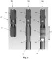
- Figs. 2 and 3 show an electrical contact terminal 1 according to an embodiment of the present disclosure in three different assembling steps.
- the electrical contact terminal 1 comprises a crimp portion 21 for electrically connecting an electrical wire 10, wherein the crimp portion 21 has a cross-section perpendicular to the longitudinal axis LA of the crimp portion 21 that has a V-shape.
- Step 1 (indicated as S1) shows the electrical contact terminal before engaging, corresponding to method step of providing a crimp portion 21 for connecting an electrical wire 10 as described elsewhere herein.
- Step 2 shows the provision of an electrical wire 10 comprising one or more wire strands 12 and an insulator 11.
- Step 3 (S3) shows the step after crimping and / or welding, preferably ultra-sonic welding.
- the crimp portion 21 maintains its V-shape and the two arms of the V-shape of the crimp portion 21 are not folded around the one or more wire strands 12 of the electrical wire 10.
- a plurality of wire strands 12 may be comprised by the electrical wire 10.
- a terminal connector 22 (which may also be referred to as a hood) may be comprised by the electrical contact terminal 1.
- the crimp portion 21 and the terminal connector 22 may be connected together in a stamping die process.
- the one or more wire strands 12 of the electrical wire 10 engaged with the crimp portion 21 do not substantially protrude from the opening of the V-shape. Further, the one or more wire strands 12 may have a textured top surface.
- the crimp portion 21 has a plurality of recesses 23, implemented as through-holes and distributed uniformly, preferably uniformly on each of the two surfaces of the crimp portion 21 that has the V-shape.
- the one or more wire strands 12 of the electrical wire 10 are at least partially pressed into the plurality of recesses 23.
- the electrical wire 10 also comprises an insulator 11 surrounding a part of the one or more wire strands 12 that is not engaged with the crimp portion 21. Further, a cross-section of the one or more wire strands 12 engaged with the crimp portion 21 has a smaller largest dimension than a cross-section of a part of the electrical wire 10 that comprises the insulator 11.
- the crimp portion 21 is elongate and the elongate part of the crimp portion 21 that is engaged with the one or more wire strands 12 of the electrical wire 10 has a length along the longitudinal axis as described elsewhere herein.
- Fig . 4 shows an electrical contact terminal 1 according to an embodiment of the present disclosure before connected to a female connector 30 in a perspective view.
- Fig. 5 correspondingly shows the electrical contact terminal 1 when connected to a female connector 30 in a perspective and cross-sectional view.
- Fig. 6 shows the electrical contact terminal 1 of Fig. 5 in a different cross-sectional view (indicated as C-C in Fig. 5 ).
- Fig. 6 indicates the angle ⁇ between the two arms of the V-shape of the crimp portion 21.
- An elongation of the two arms of the V-shape is indicated by the dashed lines.
- a cross-section of the one or more wire strands 12 of the electrical wire 10 engaged with the crimp portion 21 has a triangular shape.
- the triangular shape may have an area of at least 1 mm 2 and / or of at most 10 mm 2 , as described elsewhere herein.
- Fig. 7 shows a method 100 for assembling an electrical contact terminal, such as an electrical contact terminal as described elsewhere herein, according to an embodiment of the present disclosure.
- the method 100 comprises the steps of: providing 110 an electrical wire comprising one or more wire strands; providing 120 a crimp portion for connecting the electrical wire; engaging 130 the crimp portion at least partially with the electrical wire, for establishing an electrical connection therewith; wherein the crimp portion has a cross-section perpendicular to the longitudinal axis of the crimp portion that has a V-shape.
- engaging 130 comprises crimping and / or welding, preferably ultra-sonic welding the one or more wire strands of the electrical wire to the crimp portion.
Landscapes
- Engineering & Computer Science (AREA)
- Manufacturing & Machinery (AREA)
- Connections Effected By Soldering, Adhesion, Or Permanent Deformation (AREA)
Abstract
The present invention relates to an electrical contact terminal, in particular for use in automotive applications, the electrical contact terminal comprising: a crimp portion for connecting an electrical wire; wherein the crimp portion has a cross-section perpendicular to the longitudinal axis of the crimp portion that has a V-shape.
Description
- The present invention relates to an electrical contact terminal, in particular for use in automotive applications. Particularly, the present invention relates to an electrical contact terminal with a crimp portion. The present invention further relates to a respective method for assembling an electrical contact terminal.
- In recent years the automotive sector has been facing a shift towards electric vehicles, which are becoming more and more important and popular among consumers. This shift, in turn, is accompanied by a growing demand of electrical parts and components. This also increases the demand of electrical connection systems, which are useful to connect one electrical part to another electrical part. On the one hand such electrical connections are useful to transmit electrical power to electric consumers. On the other hand, such electrical connections facilitate the distribution of data in automotive vehicles.
- These types of electrical connection systems typically comprise an electrical wire having one or a plurality of strands for conducting electrical current and an insulator. To provide for an electrical connection, the strands are crimped to a crimp area of a terminal and said terminal can then be connected to a female connector.
- In the prior art, different solutions are proposed to provide for an electrical connection between an electrical wire and a terminal. As an example, ultra sonic welding or B-crimping are known solutions. Ultrasonic welding makes use of high-frequency ultrasonic vibrations to join the electrical wire and the terminal. When employing B-crimping, a B-shaped crimped portion is provided on the terminal to join the electrical wire and the terminal.
- These known solutions reveal several drawbacks.
- For instance, it is difficult to insert the crimped terminal into a female connector housing due to physical hindrance or obstruction by way of the crimped portion, which could easily collide with a cavity of the female connector. This makes it necessary to adapt the female connector to allow for different sizes of electrical wires. This increases costs and makes assembling more difficult.
- Against this background, there is a need to improve the presently known solutions for crimping an electrical wire to a terminal.
- It is thus an object of the present invention to overcome some or all of the deficiencies of the prior art. In particular, it is an object of the invention to provide an electrical contact terminal that allows to be easily engaged with one or more strands of an electrical wire. This should reduce the need of adapting a female connector to which the terminal can be connected. The electrical contact terminal should provide for a more flexible crimping and should facilitate employing different sizes of electrical wires. It is a general objective to reduce costs and assembling effort.
- The above-mentioned objects are at least partially achieved by the subject-matter of the independent claims. Preferred embodiments are subject of the dependent claims, and the skilled person finds hints for other suitable aspects of the present invention through the overall disclosure of the present application.
- An aspect of the invention relates to an electrical contact terminal, in particular for use in automotive applications, the electrical contact terminal comprising: a crimp portion for connecting an electrical wire; wherein the crimp portion has a cross-section perpendicular to the longitudinal axis of the crimp portion that has a V-shape, in contrast to e.g. a U-shape.
- In this manner, the present disclosure provides an electrical contact terminal that allows for an improved fit, when placed into a connector, for instance in a corresponding connector cavity of a female connector. When the crimp portion is engaged with one or more wire strands of the electrical wire, it has an improved shape such that collision thereof with cavity walls of a connector can be reduced or substantially prevented. This has the advantage that the cavity of the connector does not need to be modified or altered when different electrical wire sizes are crimped and, subsequently, connected with a connector.
- In addition, assembling of the electrical contact terminal is simplified and improved. This may also aid in reducing failures and/or damages during assembling and makes such assembling more flexible. The electrical contact terminal can hence be employed in various fields of applications whenever an electrical connection between an electrical wire and a connector via a terminal needs to be provided. The flexibility of the electrical contact terminal is thus increased.
- The "electrical contact terminal" as referred to herein may comprise the electrical wire. However, this may not necessarily be required, as already the electrical contact terminal without the electrical wire provides for the advantages as mentioned in here.
- The "crimp portion" as referred to herein may be suitable to be subjected to a crimping tool and / or an ultra-sonic welding (USW) as described elsewhere herein. The crimp portion that is comprised by the electrical contact terminal may be understood as a portion of any length along its longitudinal axis.
- The "electrical wire" as referred to herein may comprise one or more wire strands, which may alternatively be referred to as a conductor. Further, the electrical wire may comprise one or more shielding and / or an insulator. The one or more wire strands of the electrical wire are configured to provide for an electrical connection to another electrically conductive element, such as the crimp portion. In this manner, it is understood that the crimp portion can provide for connecting an electrical wire, i.e., for electrically connecting said electrical wire.
- The "longitudinal axis" of the crimp portion as referred to herein means that the crimp portion may have a longitudinal shape (which may also be referred to as an elongate shape). This could mean that the crimp portion has a dimension along one axis of the crimp portion, which is larger than one and preferably than both dimensions along the remaining axes of the crimp portion, wherein the remaining axes are substantially perpendicular to said one axis. Thereby, it is understood that the crimp portion merely has one longitudinal axis and not two or more longitudinal axes. The longitudinal axis of the crimp portion may be substantially parallel to the longitudinal axis of the electrical wire. The longitudinal axis of the crimp portion may be substantially coaxial to the longitudinal axis of the electrical wire. The skilled person understands that any electrical wire may have one longitudinal axis, which is easily discernable without detailed investigation.
- In one example, the "longitudinal axis" of the crimp portion may be parallel to a receiving direction of the electrical wire, when the electrical wire is to be engaged with the crimp portion. However, as understood by the skilled person, the "longitudinal axis" of the crimp portion may alternatively be perpendicular to a receiving direction of the electrical wire. The latter may be the case when the electrical wire is brought in engagement with the crimp portion from the top, i.e., along a vertical axis, and when the crimp portion is arranged with its longitudinal axis in a horizontal plane.
- The "cross-section" of the crimp portion as referred to herein may be understood as the cross-section of the crimp portion, which is filled by a material. Thereby, it may not be a cross-section of the crimp portion that comprises an empty space. The definition of such a cross-section is generally known to the skilled person.
- The cross-section of the crimp portion being "perpendicular to the longitudinal axis" of the crimp portion means that a normal of the cross-section is substantially parallel to the longitudinal axis of the crimp portion.
- The "V-shape" of the cross-section of the crimp portion means for instance, that a letter "V" could be recognizable for the skilled person without undue expenditure of investigation. As understood, such a V-shape may have two arms intersecting at an intersecting point.
- It is noted that when feature, aspects, and/or embodiments are described herein by the term "substantially", manufacturing tolerances usually must be taken into consideration. In this manner, minor deviations during any kind of manufacturing, assembling or the like may pertain. Further, manufacturing tolerances, aging effects, or other minor defects or the like may pertain. These are all encompassed by the term "substantially". Although not always explicitly expressed by using the term "substantially", it is understood that the elements, parts, units, shapes, and / or the like described herein may nevertheless comprise such manufacturing tolerances.
- In a preferred embodiment of the electrical contact terminal, the V-shape has an angle between its two arms of at least 5°, preferably at least 10°, preferably at least 20°, preferably at least 30°, preferably at least 40°, preferably at least 50°, preferably at least 60°, and/or of at most 160°, preferably at most 140°, preferably at most 120°, preferably at most 100°, preferably at most 80°, preferably at most 70°, preferably at most 60°.
- This ensures that an improved crimping and subsequent placing into a connector, for instance in a corresponding connector cavity of a female connector can be ensured. The angle should not be too small, as this could be detrimental for receiving one or more wire strands of the electrical wire before engaging, e.g., crimping. Further, the angle should not be too large, as this could compromise placement into a connector. The values specified in here provided an optimum compromise between these conflicting requirements.
- In a preferred embodiment of the electrical contact terminal, the electrical contact terminal further comprises the electrical wire comprising one or more wire strands, wherein, when crimped, a cross-section of the one wire strand or the plurality of wire strands of the electrical wire engaged with the crimp portion has a triangular shape.
- The cross-section of the one or more wire strands as referred to herein may be understood as the cross-section, which is filled by a material. As understood, the triangular shape of the one or more wire strands may have one or more slightly rounded corners. This may be the case for the corner of the triangular shape that is in contact with the intersecting point of the two arms of the V-shape, as there may be a bending radius present as described elsewhere herein.
- This embodiment has the advantage that the one or more wire strands substantially adopt the shape of the free space that is provided by the V-shape of the crimp portion. The triangular shape may substantially fill out the V-shape.
- In a preferred embodiment of the electrical contact terminal, the triangular shape has an area of at least 1 mm2, preferably at least 2 mm2, more preferably at least 3 mm2, most preferably at least 4 mm2, and / or of at most 10 mm2, preferably at most 8 mm2, more preferably at most 6 mm2.
- It is understood that the area of the triangular shape may substantially correspond to the area of the one or more strands before crimping. However, minor deviations may occur attributable to plastic deformations of the material or the like.
- It is appreciated that according to the electrical contact terminal described herein, different sizes of electrical wires (exemplarily specified by way of their area) can be used in conjunction with merely one size of the electrical contact terminal without necessitating the provision of an adapted connector cavity.
- In a preferred embodiment of the electrical contact terminal, when crimped, the crimp portion maintains its V-shape.
- This means that the crimp portion does not substantially alter its shape during crimping, as it typically is the case in the prior art. This is appreciated since the dimensions of the crimped electrical contact terminal may be easier to predict before crimping. Thereby, placement of the crimped electrical contact terminal in a connector can be improved. It is appreciated that this applies to any size of the electrical wire.
- In one example, the V-shape has a bending radius between its two arms of at most 1 mm, preferably at most 0.5 mm, more preferably at most 0.4 mm, more preferably at most 0.3 mm, most preferably at most 0.25 mm. It is noted that the bending radius should not be smaller than the thickness of the material, the crimp portion is composed of.
- A larger bending radius facilitates that the one or more wire strands may be more easily received in the crimp portion before engaging, e.g., crimping. However, the bending radius should not be too large as this may adversely affect placement of the crimped terminal in a female connector. The values specified in here provide an optimum compromise between these conflicting requirements.
- In a preferred embodiment of the electrical contact terminal, when crimped, the two arms of the V-shape of the crimp portion are not folded around one or more wire strands of the electrical wire, as it typically is the case in the prior art.
- This has the advantage that the two arms of the V-shape are not altered and, hence, maintain their shape to provide a more predictable fitting into a connector. In the prior art, for instance when employing B-crimping, a B-shaped crimped portion is provided on the terminal, which can adversely affect the outer dimensions thereof, which can lead to collisions in a cavity of the connector.
- In a preferred embodiment of the electrical contact terminal, when crimped, one or more wire strands of the electrical wire engaged with the crimp portion protrude from the opening of the V-shape to at most 20%, preferably at most 15%, preferably at most 10%, preferably at most 5%, preferably at most 2% of the height of the V-shape.
- The opening of the V-shape may be defined by a plane connecting the top ends, e.g., the top edges parallel to the longitudinal axis of the V-shape, of the two arms of the V-shape. Since the letter "V" may generally be understood as having only one opening, said V-shape may not have more than one opening.
- This embodiment has the advantage that the one or more wire strands do not substantially protrude from the opening, thereby, they do not interfere with cavity walls of a female connector.
- The height of the V-shape is generally understood as the length from the intersecting point of the two arms to the plane connecting the top ends of the V-shape. The length may be measured along an axis that is perpendicular to the plane connecting the top ends of the V-shape.
- When crimped, the top surface of the one or more strands may have a structure provided by the crimping tool. The top surface may be the surface opposite to the intersecting point of the two arms of the V-shape.
- In a preferred embodiment of the electrical contact terminal, the crimp portion has a plurality of recesses, wherein, when crimped, one or more wire strands of the electrical wire are at least partially pressed into the plurality of recesses.
- The plurality of recesses facilitates an improved and more secure crimping of the one or more strands and the crimp portion. The recesses may have any suitable shape, in particular, they may have a triangular, rectangular, and / or rhombic shape, which could further facilitate crimping.
- In a preferred embodiment of the electrical contact terminal, the recesses of the plurality of recesses are distributed uniformly, preferably uniformly on each of the two surfaces of the crimp portion that has the V-shape.
- This further contributes to an improved and more secure crimping. A uniform distribution may also improve manufacturing of the electrical contact terminal.
- In a preferred embodiment of the electrical contact terminal, the plurality of recesses are through-holes.
- This has the advantage that more space is provided into which the one or more wire strands can be pressed into during crimping. At the same time, the thickness of the crimp portion can be reduced to save material. Further, this may facilitate manufacturing of the electrical contact terminal, as the recesses may be simply stamped into the material thereof.
- In a preferred embodiment of the electrical contact terminal, the electrical wire comprises an insulator surrounding a part of the one or more wire strands of the electrical wire that is not engaged with the crimp portion, wherein a cross-section of the one or more wire strands of the electrical wire engaged with the crimp portion has a smaller largest dimension than a cross-section of a part of the electrical wire that comprises the insulator.
- This facilitates that placement of the crimped electrical contact terminal into a connector is improved. The bottleneck of placement may not be the one or more wire strands of the electrical wire engaged with the crimp portion. Thereby, the bottleneck of placement is independent of the crimping process. In particular, the crimped electrical contact terminal may fit into a connector even when the electrical wire is provided with different sizes. This increases flexibility of the electrical contact terminal and reduces costs.
- In a preferred embodiment of the electrical contact terminal, the crimp portion is elongate, wherein the elongate part of the crimp portion that is engaged with one or more wire strands of the electrical wire has a length of at least 1 mm, preferably at least 2 mm, preferably at least 4 mm, preferably at least 6 mm, preferably at least 8 mm, preferably at least 10 mm, and/or of at most 30 mm, preferably at most 25 mm, preferably at most 20 mm, preferably at most 18 mm, preferably at most 15 mm.
- This ensures that an optimum length of the elongate part of the crimp portion is achieved. On the one hand, the length should not be too large, as this adversely affects waste of material. On the other hand, the length should be sufficient for substantially fixing the electrical wire to the crimp portion. Thus, the inventors found that an optimum balance according to the proposed values in here could be achieved.
- It may be the case that not the overall length of the elongate part of the crimp portion is engaged, e.g., crimped, with the one or more wire strands.
- The crimp portion being elongate may be understood such that at least one dimension is larger than any of the other two dimensions. The other two dimensions may be measured along respective axes that are perpendicular to an axis along which the larger dimension is measured. Hence, one may recognize a longitudinal axis.
- As understood by the skilled person, the length as specified in here may depend on a cross-section of the electrical wire.
- In a preferred embodiment of the electrical contact terminal, one or more wire strands of the electrical wire comprises aluminum or copper, wherein the conductor element preferably consists of aluminum or copper, wherein the electrical wire preferably comprises exactly one solid wire strand, wherein the one wire solid strand preferably has a cross sectional area of at least 1 mm2, preferably at least 2 mm2, more at least 3 mm2, most preferably at least 4 mm2, and / or of at most 10 mm2, preferably at most 8 mm2, more preferably at most 6 mm2.
- These materials are mature, widely accepted in the industry, and relatively easy to procure.
- It is appreciated that according to the electrical contact terminal described herein, different sizes of exactly one solid wire strand may be used.
- A further aspect is related to a method for assembling an electrical contact terminal, such as an electrical contact terminal as described elsewhere herein, the method comprising the steps of: providing an electrical wire comprising one or more wire strands; providing a crimp portion for connecting the electrical wire; engaging the crimp portion at least partially with the electrical wire, for establishing an electrical connection therewith; wherein the crimp portion has a cross-section perpendicular to the longitudinal axis of the crimp portion that has a V-shape.
- The method comprises all advantages of the electrical contact terminal described herein. Particularly, it is noted that the method as described herein may include all aspects and/or embodiments described herein, even if not expressly described as a method but rather with reference to the electrical contact terminal. It is also to be understood that the features and advantages described with reference to the electrical contact terminal may equally be applicable to the method as described herein.
- In a preferred embodiment of the method, wherein, after engaging, a cross-section of the one or more wire strands of the electrical wire engaged with the crimp portion has a triangular shape, optionally, wherein engaging comprises crimping and / or welding, preferably ultra-sonic welding the one or more wire strands of the electrical wire to the crimp portion.
- In a preferred embodiment of the method, the crimp portion has a plurality of recesses, wherein engaging comprises pressing the one or more wire strands of the electrical wire at least partially into the plurality of recesses.
- In the following, preferred embodiments of the disclosure are disclosed by reference to the accompanying figures.
- Fig. 1:
- illustrates an electrical contact terminal with a female connector according to the prior art.
- Fig. 2:
- illustrates an electrical contact terminal according to an embodiment of the present disclosure in a top view in three different assembling steps.
- Fig. 3:
- illustrates the embodiment of
Fig. 2 in a perspective view. - Fig. 4:
- illustrates an electrical contact terminal according to an embodiment of the present disclosure before connected to a female connector in a perspective view.
- Fig. 5:
- illustrates an electrical contact terminal according to an embodiment of the present disclosure when connected to a female connector in a perspective and cross-sectional view.
- Fig. 6:
- illustrates the electrical contact terminal of
Fig. 5 in a different cross-sectional view. - Fig. 7:
- illustrates a method for assembling an electrical contact terminal according to an embodiment of the present disclosure.
- The term "and/or" is only an association relationship describing associated objects and represents that three relationships may exist. For example, A and/or B may represent three conditions: i.e., independent existence of A, existence of both A and B and independent existence of B. In addition, the character "/" in the disclosure usually represents that previous and next associated objects form an "or" relationship.
- In the subsequent passages, the invention is described with reference to the accompanying figures in more detail. It is noted that further embodiments are certainly possible, and the below explanations are provided by way of example only, without limitation. Throughout the present figures and specification, the same reference numerals refer to the same elements. The figures may not be to scale, and the relative size, proportions, and depiction of elements in the figures may be exaggerated for clarity, illustration, and convenience.
-
Fig. 1 shows anelectrical contact terminal 1p with afemale connector 30 according to the prior art. Theelectrical contact terminal 1p comprises anelectrical wire 10, having aninsulator 11 and one ormore wire strands 12. Acrimp portion 21p is shown having a B-shape. Two cross-sections A-A and B-B are indicated depictingcollision portions 40p with walls of acavity 31 of thefemale connector 30 on the right-hand side ofFig. 1 . -
Figs. 2 and3 show an electrical contact terminal 1 according to an embodiment of the present disclosure in three different assembling steps. - The electrical contact terminal 1 comprises a
crimp portion 21 for electrically connecting anelectrical wire 10, wherein thecrimp portion 21 has a cross-section perpendicular to the longitudinal axis LA of thecrimp portion 21 that has a V-shape. Step 1 (indicated as S1) shows the electrical contact terminal before engaging, corresponding to method step of providing acrimp portion 21 for connecting anelectrical wire 10 as described elsewhere herein. Step 2 (S2) shows the provision of anelectrical wire 10 comprising one ormore wire strands 12 and aninsulator 11. Step 3 (S3) shows the step after crimping and / or welding, preferably ultra-sonic welding. - As best seen in step 3, when crimped, the
crimp portion 21 maintains its V-shape and the two arms of the V-shape of thecrimp portion 21 are not folded around the one ormore wire strands 12 of theelectrical wire 10. Although depicted as exactly onewire strand 12, a plurality ofwire strands 12 may be comprised by theelectrical wire 10. - Further, a terminal connector 22 (which may also be referred to as a hood) may be comprised by the electrical contact terminal 1. The
crimp portion 21 and theterminal connector 22 may be connected together in a stamping die process. - As best seen in step 3 in
Fig. 3 , the one ormore wire strands 12 of theelectrical wire 10 engaged with thecrimp portion 21 do not substantially protrude from the opening of the V-shape. Further, the one ormore wire strands 12 may have a textured top surface. - The
crimp portion 21 has a plurality of recesses 23, implemented as through-holes and distributed uniformly, preferably uniformly on each of the two surfaces of thecrimp portion 21 that has the V-shape. When crimped, the one ormore wire strands 12 of theelectrical wire 10 are at least partially pressed into the plurality of recesses 23. - The
electrical wire 10 also comprises aninsulator 11 surrounding a part of the one ormore wire strands 12 that is not engaged with thecrimp portion 21. Further, a cross-section of the one ormore wire strands 12 engaged with thecrimp portion 21 has a smaller largest dimension than a cross-section of a part of theelectrical wire 10 that comprises theinsulator 11. - The
crimp portion 21 is elongate and the elongate part of thecrimp portion 21 that is engaged with the one ormore wire strands 12 of theelectrical wire 10 has a length along the longitudinal axis as described elsewhere herein. -
Fig. 4 shows an electrical contact terminal 1 according to an embodiment of the present disclosure before connected to afemale connector 30 in a perspective view.Fig. 5 correspondingly shows the electrical contact terminal 1 when connected to afemale connector 30 in a perspective and cross-sectional view. - The cross-section is made through a front connector portion of the
female connector 30. Thereby, acavity 31 of thefemale connector 30 can be seen.Fig. 6 shows the electrical contact terminal 1 ofFig. 5 in a different cross-sectional view (indicated as C-C inFig. 5 ). -
Fig. 6 indicates the angle α between the two arms of the V-shape of thecrimp portion 21. An elongation of the two arms of the V-shape is indicated by the dashed lines. In addition, a cross-section of the one ormore wire strands 12 of theelectrical wire 10 engaged with thecrimp portion 21 has a triangular shape. The triangular shape may have an area of at least 1 mm2 and / or of at most 10 mm2, as described elsewhere herein. - No collision between the one or
more wire strands 12 of theelectrical wire 10 engaged with thecrimp portion 21 and walls of thecavity 31 of thefemale connector 30 occurs. -
Fig. 7 shows amethod 100 for assembling an electrical contact terminal, such as an electrical contact terminal as described elsewhere herein, according to an embodiment of the present disclosure. Themethod 100 comprises the steps of: providing 110 an electrical wire comprising one or more wire strands; providing 120 a crimp portion for connecting the electrical wire; engaging 130 the crimp portion at least partially with the electrical wire, for establishing an electrical connection therewith; wherein the crimp portion has a cross-section perpendicular to the longitudinal axis of the crimp portion that has a V-shape. - Optionally, engaging 130 comprises crimping and / or welding, preferably ultra-sonic welding the one or more wire strands of the electrical wire to the crimp portion.
- It is to be noted that the scope of protection is determined by the claims and is not limited by the embodiments disclosed in the above figures.
-
- 1p
- prior art: electrical contact terminal
- 21p
- prior art: crimp portion
- 40p
- prior art: collision portion
- 1
- electrical contact terminal
- 10
- electrical wire
- 11
- insulator
- 12
- one or more wire strands
- 21
- crimp portion
- 22
- terminal connector
- 23
- recesses
- 30
- female connector
- 31
- cavity
- 100
- method
- 110
- providing
- 120
- providing
- 130
- engaging
- LA
- longitudinal axis of the crimp portion
- α
- angle between the two arms of the V-shape
- S1
- Step 1
- S2
- Step 2
- S3
- Step 3
Claims (15)
- An electrical contact terminal (1), in particular for use in automotive applications, the electrical contact terminal (1) comprising:a crimp portion (21) for connecting an electrical wire (10);wherein the crimp portion (21) has a cross-section perpendicular to the longitudinal axis (LA) of the crimp portion (21) that has a V-shape.
- The electrical contact terminal (1) according to claim 1, wherein the V-shape has an angle (a) between its two arms of at least 5°, preferably at least 10°, preferably at least 20°, preferably at least 30°, preferably at least 40°, preferably at least 50°, preferably at least 60°, and/or
of at most 160°, preferably at most 140°, preferably at most 120°, preferably at most 100°, preferably at most 80°, preferably at most 70°, preferably at most 60°. - The electrical contact terminal (1) according to any one of the preceding claims, further comprising the electrical wire (10) comprising one or more wire strands (12), wherein, when crimped, a cross-section of the one wire strand or a cross section of a plurality of wire strands (12) of the electrical wire (10) engaged with the crimp portion (21) has a triangular shape.
- The electrical contact terminal (1) according to claim 3, wherein the triangular shape has an area of at least 1 mm2, preferably at least 2 mm2, more preferably at least 3 mm2, most preferably at least 4 mm2,
and / or of at most 10 mm2, preferably at most 8 mm2, more preferably at most 6 mm2. - The electrical contact terminal (1) according to any one of the preceding claims, wherein, when crimped, the crimp portion (21) maintains its V-shape.
- The electrical contact terminal (1) according to any one of the preceding claims, wherein, when crimped, the two arms of the V-shape of the crimp portion (21) are not folded around one or more wire strands (12) of the electrical wire (10).
- The electrical contact terminal (1) according to the preceding claim, wherein, when crimped, one or more wire strands (12) of the electrical wire (10) engaged with the crimp portion (21) protrude from the opening of the V-shape to at most 20%, preferably at most 15%, preferably at most 10%, preferably at most 5%, preferably at most 2% of the height of the V-shape.
- The electrical contact terminal (1) according to any one of the preceding claims, wherein the crimp portion (21) has a plurality of recesses (23), wherein, when crimped, one or more wire strands (12) of the electrical wire (10) are at least partially pressed into the plurality of recesses (23).
- The electrical contact terminal (1) according claim 8, wherein the recesses (23) of the plurality of recesses (23) are distributed uniformly, preferably uniformly on each of the two surfaces of the crimp portion (21) that has the V-shape.
- The electrical contact terminal (1) according to any one of the preceding claims 8 or 9, wherein the plurality of recesses (23) are through-holes.
- The electrical contact terminal (1) according to any one of the preceding claims, wherein the electrical wire (10) comprises an insulator (11) surrounding a part of the one or more wire strands (12) of the electrical wire (10) that is not engaged with the crimp portion (21),
wherein a cross-section of the one or more wire strands (12) of the electrical wire (10) engaged with the crimp portion (21) has a smaller largest dimension than a cross-section of a part of the electrical wire (10) that comprises the insulator. - The electrical contact terminal (1) according to any one of the preceding claims, wherein the crimp portion (21) is elongate, wherein the elongate part of the crimp portion (21) that is engaged with one or more wire strands (12) of the electrical wire (10) has a length of at least 1 mm, preferably at least 2 mm, preferably at least 4 mm, preferably at least 6 mm, preferably at least 8 mm, preferably at least 10 mm, and/or
of at most 30 mm, preferably at most 25 mm, preferably at most 20 mm, preferably at most 18 mm, preferably at most 15 mm. - The electrical contact terminal (1) according to any one of the preceding claims, wherein one or more wire strands (12) of the electrical wire comprises aluminum or copper, wherein the conductor element preferably consists of aluminum or copper,wherein the electrical wire (10) preferably comprises exactly one solid wire strand,wherein the one solid wire strand preferably has a cross sectional area of at least 1 mm2, preferably at least 2 mm2, more at least 3 mm2, most preferably at least 4 mm2, and / or of at most 10 mm2, preferably at most 8 mm2, more preferably at most 6 mm2.
- A method (100) for assembling an electrical contact terminal (1), such as an electrical contact terminal (1) according to any one of the preceding claims, the method comprising the steps of:providing (110) an electrical wire (10) comprising one or more wire strands (12);providing (120) a crimp portion (21) for connecting the electrical wire (10);engaging (130) the crimp portion (21) at least partially with the electrical wire (10), for establishing an electrical connection therewith;wherein the crimp portion (21) has a cross-section perpendicular to the longitudinal axis of the crimp portion (21) that has a V-shape.
- The method (100) of the preceding claim, wherein, after engaging, a cross-section of the one or more wire strands (12) of the electrical wire (10) engaged with the crimp portion (21) has a triangular shape,
optionally, wherein engaging comprises crimping and / or welding, preferably ultra-sonic welding the one or more wire strands (12) of the electrical wire (10) to the crimp portion (21).
Priority Applications (1)
| Application Number | Priority Date | Filing Date | Title |
|---|---|---|---|
| EP23198701.7A EP4528941A1 (en) | 2023-09-21 | 2023-09-21 | Electrical contact terminal with a crimp portion and assembling method thereof |
Applications Claiming Priority (1)
| Application Number | Priority Date | Filing Date | Title |
|---|---|---|---|
| EP23198701.7A EP4528941A1 (en) | 2023-09-21 | 2023-09-21 | Electrical contact terminal with a crimp portion and assembling method thereof |
Publications (1)
| Publication Number | Publication Date |
|---|---|
| EP4528941A1 true EP4528941A1 (en) | 2025-03-26 |
Family
ID=88147130
Family Applications (1)
| Application Number | Title | Priority Date | Filing Date |
|---|---|---|---|
| EP23198701.7A Pending EP4528941A1 (en) | 2023-09-21 | 2023-09-21 | Electrical contact terminal with a crimp portion and assembling method thereof |
Country Status (1)
| Country | Link |
|---|---|
| EP (1) | EP4528941A1 (en) |
Citations (4)
| Publication number | Priority date | Publication date | Assignee | Title |
|---|---|---|---|---|
| US3332054A (en) * | 1964-07-27 | 1967-07-18 | Thomas & Betts Corp | Electrical terminal with v-shaped barrel |
| CA961565A (en) * | 1971-04-29 | 1975-01-21 | Molex Incorporated | Crimp terminal for aluminum wire |
| US20170324172A1 (en) * | 2016-05-03 | 2017-11-09 | Tyco Electronics Corporation | Electrical crimp terminal |
| US10998647B2 (en) * | 2017-05-29 | 2021-05-04 | Japan Aviation Electronics Industry, Ltd. | Harness with a wire terminal |
-
2023
- 2023-09-21 EP EP23198701.7A patent/EP4528941A1/en active Pending
Patent Citations (4)
| Publication number | Priority date | Publication date | Assignee | Title |
|---|---|---|---|---|
| US3332054A (en) * | 1964-07-27 | 1967-07-18 | Thomas & Betts Corp | Electrical terminal with v-shaped barrel |
| CA961565A (en) * | 1971-04-29 | 1975-01-21 | Molex Incorporated | Crimp terminal for aluminum wire |
| US20170324172A1 (en) * | 2016-05-03 | 2017-11-09 | Tyco Electronics Corporation | Electrical crimp terminal |
| US10998647B2 (en) * | 2017-05-29 | 2021-05-04 | Japan Aviation Electronics Industry, Ltd. | Harness with a wire terminal |
Similar Documents
| Publication | Publication Date | Title |
|---|---|---|
| US9853368B2 (en) | Electrical crimp terminal | |
| CN101842940B (en) | Crimping terminal, cable with terminal and method for manufacturing such cable | |
| US6749457B2 (en) | Crimp terminal | |
| US9768526B2 (en) | Crimp-connection structural body, wire harness, method of manufacturing crimp-connection structural body, and device of manufacturing crimp-connection structural body | |
| KR102710699B1 (en) | Crimp for connecting wires | |
| JP6921262B2 (en) | Cable assembly | |
| US20180197660A1 (en) | Manufacturing method for terminal-equipped electric wire | |
| US20150236458A1 (en) | Hf coaxial cable with angular plug connection, and a method for producing same | |
| KR20150121013A (en) | Cylindrical body, crimping terminal, method for manufacturing said body and said terminal, and device for manufacturing said crimping terminal | |
| US7316581B2 (en) | Terminal fitting and method of attaching the same | |
| EP2266167B1 (en) | Electrical terminal system | |
| JP2004055475A (en) | Connection structure between coaxial cable and coaxial connector | |
| JP7643810B2 (en) | CRIMP CONTACTS, CRIMP CONNECTIONS, AND METHODS FOR FORMING CRIMP CONNECTIONS - Patent application | |
| US11641068B2 (en) | Electrical crimp terminal for electrical wire | |
| US8272901B2 (en) | Crimp contacts and electrical connector assemblies including the same | |
| CN1625003A (en) | Automotive electrical connector box | |
| US10389077B2 (en) | HF coaxial cable with angular plug connection | |
| US20250279593A1 (en) | Electric cable or electric wire provided with a plug contour for directly plugging into a mating plug | |
| EP0398342A1 (en) | A crimp terminal and its wire crimping structure | |
| WO2013110503A1 (en) | Electrical contact terminal comprising a crimping section | |
| US20240186725A1 (en) | Terminal-equipped wire and method for manufacturing terminal-equipped wire | |
| US20240178583A1 (en) | Crimp terminal and terminal-fitted electric wire | |
| JP2024151515A (en) | Crimp terminal with electric wire and method for manufacturing the same | |
| JP2024100334A (en) | Terminal fittings and wires with terminals | |
| CN115207649A (en) | Terminal-equipped electric wire and method for manufacturing terminal-equipped electric wire |
Legal Events
| Date | Code | Title | Description |
|---|---|---|---|
| PUAI | Public reference made under article 153(3) epc to a published international application that has entered the european phase |
Free format text: ORIGINAL CODE: 0009012 |
|
| STAA | Information on the status of an ep patent application or granted ep patent |
Free format text: STATUS: THE APPLICATION HAS BEEN PUBLISHED |
|
| AK | Designated contracting states |
Kind code of ref document: A1 Designated state(s): AL AT BE BG CH CY CZ DE DK EE ES FI FR GB GR HR HU IE IS IT LI LT LU LV MC ME MK MT NL NO PL PT RO RS SE SI SK SM TR |
|
| STAA | Information on the status of an ep patent application or granted ep patent |
Free format text: STATUS: REQUEST FOR EXAMINATION WAS MADE |
|
| 17P | Request for examination filed |
Effective date: 20250916 |