EP4528920A1 - In degree-adjustable wifi mounting bracket for access point and antenna - Google Patents
In degree-adjustable wifi mounting bracket for access point and antenna Download PDFInfo
- Publication number
- EP4528920A1 EP4528920A1 EP23199256.1A EP23199256A EP4528920A1 EP 4528920 A1 EP4528920 A1 EP 4528920A1 EP 23199256 A EP23199256 A EP 23199256A EP 4528920 A1 EP4528920 A1 EP 4528920A1
- Authority
- EP
- European Patent Office
- Prior art keywords
- mounting apparatus
- antenna
- movement
- movement plate
- plate
- Prior art date
- Legal status (The legal status is an assumption and is not a legal conclusion. Google has not performed a legal analysis and makes no representation as to the accuracy of the status listed.)
- Pending
Links
Images


Classifications
-
- H—ELECTRICITY
- H01—ELECTRIC ELEMENTS
- H01Q—ANTENNAS, i.e. RADIO AERIALS
- H01Q1/00—Details of, or arrangements associated with, antennas
- H01Q1/12—Supports; Mounting means
- H01Q1/1207—Supports; Mounting means for fastening a rigid aerial element
- H01Q1/1221—Supports; Mounting means for fastening a rigid aerial element onto a wall
-
- H—ELECTRICITY
- H01—ELECTRIC ELEMENTS
- H01Q—ANTENNAS, i.e. RADIO AERIALS
- H01Q1/00—Details of, or arrangements associated with, antennas
- H01Q1/007—Details of, or arrangements associated with, antennas specially adapted for indoor communication
-
- H—ELECTRICITY
- H01—ELECTRIC ELEMENTS
- H01Q—ANTENNAS, i.e. RADIO AERIALS
- H01Q1/00—Details of, or arrangements associated with, antennas
- H01Q1/12—Supports; Mounting means
- H01Q1/1207—Supports; Mounting means for fastening a rigid aerial element
- H01Q1/1228—Supports; Mounting means for fastening a rigid aerial element on a boom
-
- H—ELECTRICITY
- H01—ELECTRIC ELEMENTS
- H01Q—ANTENNAS, i.e. RADIO AERIALS
- H01Q1/00—Details of, or arrangements associated with, antennas
- H01Q1/12—Supports; Mounting means
- H01Q1/125—Means for positioning
-
- H—ELECTRICITY
- H01—ELECTRIC ELEMENTS
- H01Q—ANTENNAS, i.e. RADIO AERIALS
- H01Q1/00—Details of, or arrangements associated with, antennas
- H01Q1/12—Supports; Mounting means
- H01Q1/22—Supports; Mounting means by structural association with other equipment or articles
- H01Q1/2291—Supports; Mounting means by structural association with other equipment or articles used in Bluetooth® or Wi-Fi® devices of Wireless Local Area Networks [WLAN]
Definitions
- the invention relates to a mounting apparatus used for the connection of antennas and Wi-Fi devices in the business centers, offices, hotels, sports centers, shopping malls, conference halls and schools.
- the invention relates in particular to a mounting apparatus, which enables the Wi-Fi devices and the antennas used as signal boosters to be mounted together and further enables the antennas to be positioned vertically and horizontally in an angled manner in a mounting area.
- Wi-Fi Wireless Fidelity
- the brackets which enable the Wi-Fi devices to be used by way of being fixed to a wall, are employed for the internet access in the indoor and outdoor spaces.
- these brackets are intended only for fixing a Wi-Fi device to a wall and are not suitable for mounting the antennas, which are used together with the Wi-Fi devices.
- the installation of the wireless network is quite important for the internet performance and the efficient use of the web.
- a reinforced concrete wall prevents the computers or smart devices from receiving the signals. In order to prevent such problems, it is important to avoid the obstacles that would deteriorate the signal quality.
- the data networks are unable to satisfy the demands and the needs of the users and lead to the inability to adjust the data network signals when necessary.
- a multifunctional mounting bracket According to said invention, a second mounting base, capable of moving along the vertical axis, is disposed on a first mounting base.
- a RFID (Radio Frequency Identification) antenna for the RFID technology is connected on said second mounting base and the installation angle of said antenna is varied by means of the vertical motion of the second mounting base.
- the first mounting base is mounted by way of being rotated during the mounting. However, the rotation angle of the first mounting base may not be changed after the mounting. This leads to the fact that said mounting bracket is adjustable only by a vertical angle.
- the mounting bracket since the mounting bracket includes the mounting base only for a RFID antenna, it is not suitable for the simultaneous use of a Wi-Fi device and an antenna.
- the document no. US9692109 may be mentioned as an example of the state of the art.
- Said document relates to the antennas, the access points (radio transmission devices) and a mounting apparatus, which enable the same to be positioned together in such a way that they will operate as a single device instead of two separate parts or components.
- the mounting apparatus basically comprises a base and a tray attached to said base in a rotatable manner. An access point is fixed on said base and the antenna is fixed on the tray. Even though the antenna and the access point are enabled to be mounted together on the mounting apparatus according to said invention, the tray is allowed to move only by a vertical angle. Therefore, it is not possible for the antenna to move by a horizontal angle.
- the most important object of the invention is to present a mounting apparatus, which consists of a small number of parts, is easy to mount, is of low cost and makes it possible to mount the devices (Wi-Fi, antenna) on different axes with its simple structure.
- a primary object of the invention is to present a mounting apparatus, which enables the Wi-Fi devices and the antennas used as signal boosters to be mounted together.
- An object of the invention is to present a mounting apparatus, which enables the antennas that are mounted along with the Wi-Fi devices to be positioned vertically and horizontally in an angled manner in a mounting area.
- Another object of the invention is to present a mounting apparatus, which, owing to the ability to adjust the position of the antenna vertically and horizontally, enables the data network signals to be correctly directed to the areas of use and accordingly, enables the data network signals to be distributed to the users in a correct and efficient manner.
- Another object of the invention is to present a mounting apparatus, which enables the antennas that are mounted together with the Wi-Fi devices to be adjusted according to the conditions of use and when necessary upon a change in the circumstances.
- Another object of the invention is to present a mounting apparatus, which enables the elimination of the problems encountered in the internet access in the indoor and outdoor spaces due to the signal deterioration.
- the invention is a mounting apparatus used for the connection of a Wi-Fi device and a signal booster antenna, said mounting apparatus comprising
- Figure 1 provides a view of the mounting apparatus according to the invention in the disassembled state.
- the mounting apparatus comprises in its most basic form a connection bracket (10) connected to a wall, a connection pipe (20) extending downward from the lower surface of the connection bracket (10), a lower connection bracket (30) located on the lower surface of the connection pipe (20) and enabling a Wi-Fi device (50) to be connected preferably by means of an intermediate connection bracket (40), a neck fixing member (60) performing rotational movement on the connection pipe (20), a movement plate (70) extending in the form of a semicircle downward from the side surface of the neck fixing member (60), a movable connection member (80) moving up and down inside the curved channel (71) on the movement plate (70) and enabling an antenna (100) to be connected to the movement plate (70), and a reinforcing plate (90) located on the movement plate (70).
- connection pipe (20) is present on the lower surface of the connection bracket (10), which enables the mounting bracket according to the invention to be connected to a wall.
- a lower connection bracket (30) is located on the lower surface of the connection pipe (20) extending downward from the lower surface of the connection bracket (10).
- the Wi-Fi device (50) is connected to the lower surface of said lower connection bracket (30).
- An intermediate connection bracket (40), preferably fixed to the lower connection bracket (30), may preferably be used in order to connect the Wi-Fi device (50) to the lower connection bracket (30).
- At least one neck fixing member (60), which performs rotational movement through 360°, is present on the connection pipe (20).
- Said neck fixing member (60) is fixed on the connection pipe (20) via at least one bolt (61) and performs the rotational movement as a result of said bolt being loosened.
- the ability of rotational movement on the x-axis is provided by means of said neck fixing member (60), it is also made possible to perform the fixation at the desired rotation angle by means of the bolts (61).
- the movement plate (70) is provided with the ability of multi-directional movement in the directions of Y1-Y2, by means of the channel (71) having a semicircular form.
- a movement plate (70) with the shape of a semicircle extends downward from the side surface of the neck fixing member (60). Said movement plate (70) performs the rotational movement together with the neck fixing member (60).
- the movement plate (70) is the component to which the antenna (100) intended for boosting the signal of the Wi-Fi device (50) is connected, wherein said movement plate (70) enables said antenna (100) to be positioned horizontally and vertically at the desired angle. In this way, it becomes possible to direct the data network signals to different areas.
- a curved channel (71) is formed on the movement plate (70).
- Figure 3 illustrates the movable connection member (80) on said channel (71), said movable connection member (80) being fixed mutually to both sides of the movement plate (70) preferably by means of the bolt (61).
- the movable connection member (80) which enables the antenna (100) to be connected to the movement plate (70), is moved on the channel (71) having the form of a semi crescent, i.e. in the directions Y1-Y2 along said channel (71), as a result of said bolts (61) being loosened.
- the antenna (100) Owing to the movable connection member (80) moving up and down inside the channel (71), the antenna (100) is enabled to be positioned vertically at the desired angle.
- the horizontal movement of the antenna (100) is achieved by means of the rotational movement of the neck fixing member (60) and of the movement plate (70) together with the neck fixing member (60) on the connection pipe (20).
- At least one reinforcing plate (90) with a structure compatible with the form of the movement plate (70) is present on said movement plate (70).
- the reinforcing plate (90) is placed on the inner surface of said movement plate (70) with the form of a crescent and is fixed by way of welding or by means of a tab insert (72) fitted in the tab seats (91).
- This plate by generating high resistance and strength effect in this zone, prevents the movement plate (70) from undergoing deformation.
- the fixing is achieved by bending the tab inserts or by performing the spot welding.
- connection pipe (20) there may be more than one neck fixing member (60) present on the connection pipe (20).
- the length of the connection pipe (20) may vary accordingly. While the connection pipe (20) may preferably have an extensible structure, it is also possible to for the same to have a longer configuration according to the place of use.
- the mounting apparatus includes a reinforcing bend (74), which is cut in one go by way of laser cut and is formed with a one-piece structure on the concave surface of said movement plate (70) by means of the bending technique (see Figure 3 ).
- connection bracket (10) is connected to the surface of the wall and the Wi-Fi device (50) is connected to the lower surface of the lower connection bracket (30) preferably by means of the intermediate connection bracket (40).
- Said intermediate connection bracket (40) is made from a plastic-based lightweight material and is thus able to provide convenience in the mounting as well as minimizing the damages on and the contacts with the Wi-Fi device (50) during the mounting.
- the antenna (100) is connected to the lower surface of the movable connection members (80) on the channel (71) of the movement plate (70).
- the neck fixing member (60) is loosened to move the antenna (100) horizontally by the desired angle, the movement plate (70) rotates as a result of the rotational movement of the neck fixing member (60) along the x-axis on the connection pipe (20), and the antenna (100) is enabled to be positioned horizontally at the desired angle.
- the movement plate (70) has an extension (73), which extends with a straight angle towards the mounting surface of said neck fixing member (60).
- the movable connection member (80) is loosened in order to move the antenna (100) vertically by the desired angle and the antenna (100) is enabled to be positioned vertically at the desired angle as a result of moving the movable connection member (80) up and down on the channel (71).
Landscapes
- Engineering & Computer Science (AREA)
- Computer Networks & Wireless Communication (AREA)
- Support Of Aerials (AREA)
Abstract
The invention relates to a mounting apparatus used for the connection of a Wi-Fi device (50) and a signal booster antenna (100). The invention is characterized in that the mounting apparatus comprises a movement plate (70) extending in the form of a semicircle downward from the side surface a neck fixing member (60) and performing the rotational movement together with the neck fixing member (60) in order to enable the antenna (100) to be positioned horizontally at the desired angle, a curved channel (71) located on the movement plate (70), and a movable connection member (80) moving up and down inside the curved channel (71) and enabling the antenna (100) fixed to the lower surface thereof to be connected to the movement plate (70) by way of being positioned vertically at the desired angle.
Description
- The invention relates to a mounting apparatus used for the connection of antennas and Wi-Fi devices in the business centers, offices, hotels, sports centers, shopping malls, conference halls and schools.
- The invention relates in particular to a mounting apparatus, which enables the Wi-Fi devices and the antennas used as signal boosters to be mounted together and further enables the antennas to be positioned vertically and horizontally in an angled manner in a mounting area.
- Wi-Fi (Wireless Fidelity) is the most popular method for connecting to the wireless internet. Today, the wireless connection domains constitute the basis for the digital communication. A safe and adequate data network is needed for transmitting and receiving the digital information in every field where the use of internet is necessary.
- According to the current practice, the brackets, which enable the Wi-Fi devices to be used by way of being fixed to a wall, are employed for the internet access in the indoor and outdoor spaces. However, these brackets are intended only for fixing a Wi-Fi device to a wall and are not suitable for mounting the antennas, which are used together with the Wi-Fi devices. On the other hand, it is not possible to distribute the signals of the Wi-Fi devices to the users in an accurate and proper manner with the brackets used according to the state of the art. The installation of the wireless network is quite important for the internet performance and the efficient use of the web. For example, a reinforced concrete wall prevents the computers or smart devices from receiving the signals. In order to prevent such problems, it is important to avoid the obstacles that would deteriorate the signal quality. However, in the installations realized with the bracket structures according to the state of the art, the data networks are unable to satisfy the demands and the needs of the users and lead to the inability to adjust the data network signals when necessary.
- Consequently, the need has arisen to provide a mounting bracket, which enables the Wi-Fi devices and the signal booster antennas to be adjusted together and in different directions in a manner that suits the need, even when the circumstances change.
- The document no.
CN205896629 found in the literature search may be mentioned as an example of the state of the art. Said document relates to a multifunctional mounting bracket. According to said invention, a second mounting base, capable of moving along the vertical axis, is disposed on a first mounting base. A RFID (Radio Frequency Identification) antenna for the RFID technology is connected on said second mounting base and the installation angle of said antenna is varied by means of the vertical motion of the second mounting base. The first mounting base is mounted by way of being rotated during the mounting. However, the rotation angle of the first mounting base may not be changed after the mounting. This leads to the fact that said mounting bracket is adjustable only by a vertical angle. Moreover, since the mounting bracket includes the mounting base only for a RFID antenna, it is not suitable for the simultaneous use of a Wi-Fi device and an antenna. - The document no.
US9692109 - Consequently, the presence of the above-mentioned problems and the inadequacy of the available solutions have made it necessary to carry out an improvement in the relevant art.
- The most important object of the invention is to present a mounting apparatus, which consists of a small number of parts, is easy to mount, is of low cost and makes it possible to mount the devices (Wi-Fi, antenna) on different axes with its simple structure.
- A primary object of the invention is to present a mounting apparatus, which enables the Wi-Fi devices and the antennas used as signal boosters to be mounted together.
- An object of the invention is to present a mounting apparatus, which enables the antennas that are mounted along with the Wi-Fi devices to be positioned vertically and horizontally in an angled manner in a mounting area.
- Another object of the invention is to present a mounting apparatus, which, owing to the ability to adjust the position of the antenna vertically and horizontally, enables the data network signals to be correctly directed to the areas of use and accordingly, enables the data network signals to be distributed to the users in a correct and efficient manner.
- Another object of the invention is to present a mounting apparatus, which enables the antennas that are mounted together with the Wi-Fi devices to be adjusted according to the conditions of use and when necessary upon a change in the circumstances.
- Another object of the invention is to present a mounting apparatus, which enables the elimination of the problems encountered in the internet access in the indoor and outdoor spaces due to the signal deterioration.
- In order to achieve the above-mentioned objects and all the other objects possible to become evident from the detailed description, the invention is a mounting apparatus used for the connection of a Wi-Fi device and a signal booster antenna, said mounting apparatus comprising
- a connection bracket connected to a wall,
- a connection pipe extending downward from the lower surface of the connection bracket,
- a lower connection bracket located on the lower surface of the connection pipe and enabling the Wi-Fi device to be connected,
- at least one neck fixing member located on the connection pipe and performing rotational movement on the connection pipe,
- a movement plate extending in the form of a semicircle downward from the side surface of the neck fixing member and performing rotational movement together with the neck fixing member in order to enable the antenna to be positioned horizontally at the desired angle,
- a curved channel located on the movement plate, and
- a movable connection member moving up and down inside the curved channel and enabling the antenna fixed to the lower surface thereof to be positioned vertically at the desired angle to thereby be connected to the movement plate.
-
-
Figure 1 : A view of the mounting bracket according to the invention in the disassembled state -
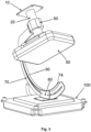
Figure 2 : A view of the mounting bracket according to the invention in a state assembled with a Wi-Fi device and an antenna -
Figure 3 : Another view of the mounting bracket according to the invention in a state assembled with a Wi-Fi device and an antenna -
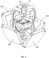
Figure 4 : A view of the mounting bracket according to an alternative embodiment of the invention in a state assembled with a Wi-Fi device and an antenna -
- 10. Connection bracket
- 20. Connection pipe
- 30. Lower connection bracket
- 40. Intermediate connection bracket
- 50. Wi-Fi device
- 60. Neck fixing member
- 61. Connection bolt
- 70. Movement plate
- 71. Channel
- 72. Tab insert
- 73. Extension
- 74. Reinforcing bend
- 80. Movable connection member
- 90. Reinforcing plate
- 91. Tab seat
- 100. Antenna
-
Figure 1 provides a view of the mounting apparatus according to the invention in the disassembled state. Accordingly, the mounting apparatus comprises in its most basic form a connection bracket (10) connected to a wall, a connection pipe (20) extending downward from the lower surface of the connection bracket (10), a lower connection bracket (30) located on the lower surface of the connection pipe (20) and enabling a Wi-Fi device (50) to be connected preferably by means of an intermediate connection bracket (40), a neck fixing member (60) performing rotational movement on the connection pipe (20), a movement plate (70) extending in the form of a semicircle downward from the side surface of the neck fixing member (60), a movable connection member (80) moving up and down inside the curved channel (71) on the movement plate (70) and enabling an antenna (100) to be connected to the movement plate (70), and a reinforcing plate (90) located on the movement plate (70). - As can be seen in
Figure 2 , a connection pipe (20) is present on the lower surface of the connection bracket (10), which enables the mounting bracket according to the invention to be connected to a wall. A lower connection bracket (30) is located on the lower surface of the connection pipe (20) extending downward from the lower surface of the connection bracket (10). The Wi-Fi device (50) is connected to the lower surface of said lower connection bracket (30). An intermediate connection bracket (40), preferably fixed to the lower connection bracket (30), may preferably be used in order to connect the Wi-Fi device (50) to the lower connection bracket (30). - At least one neck fixing member (60), which performs rotational movement through 360°, is present on the connection pipe (20). Said neck fixing member (60) is fixed on the connection pipe (20) via at least one bolt (61) and performs the rotational movement as a result of said bolt being loosened. While the ability of rotational movement on the x-axis is provided by means of said neck fixing member (60), it is also made possible to perform the fixation at the desired rotation angle by means of the bolts (61). At the same time, the movement plate (70) is provided with the ability of multi-directional movement in the directions of Y1-Y2, by means of the channel (71) having a semicircular form.
- A movement plate (70) with the shape of a semicircle extends downward from the side surface of the neck fixing member (60). Said movement plate (70) performs the rotational movement together with the neck fixing member (60). The movement plate (70) is the component to which the antenna (100) intended for boosting the signal of the Wi-Fi device (50) is connected, wherein said movement plate (70) enables said antenna (100) to be positioned horizontally and vertically at the desired angle. In this way, it becomes possible to direct the data network signals to different areas.
- A curved channel (71) is formed on the movement plate (70).
Figure 3 illustrates the movable connection member (80) on said channel (71), said movable connection member (80) being fixed mutually to both sides of the movement plate (70) preferably by means of the bolt (61). The movable connection member (80), which enables the antenna (100) to be connected to the movement plate (70), is moved on the channel (71) having the form of a semi crescent, i.e. in the directions Y1-Y2 along said channel (71), as a result of said bolts (61) being loosened. - Owing to the movable connection member (80) moving up and down inside the channel (71), the antenna (100) is enabled to be positioned vertically at the desired angle. The horizontal movement of the antenna (100) is achieved by means of the rotational movement of the neck fixing member (60) and of the movement plate (70) together with the neck fixing member (60) on the connection pipe (20).
- At least one reinforcing plate (90) with a structure compatible with the form of the movement plate (70) is present on said movement plate (70). The reinforcing plate (90) is placed on the inner surface of said movement plate (70) with the form of a crescent and is fixed by way of welding or by means of a tab insert (72) fitted in the tab seats (91). This plate, by generating high resistance and strength effect in this zone, prevents the movement plate (70) from undergoing deformation. After the process of fitting the tab insert (72) in said tab seats (91) is completed, the fixing is achieved by bending the tab inserts or by performing the spot welding.
- As can be seen in
Figure 4 , in the mounting apparatus according to the invention, there may be more than one neck fixing member (60) present on the connection pipe (20). Thus, it becomes possible to connect the movement plate (70) to each neck fixing member (60) and perform the mounting of a plurality of antennas (100) on the mounting bracket. The length of the connection pipe (20) may vary accordingly. While the connection pipe (20) may preferably have an extensible structure, it is also possible to for the same to have a longer configuration according to the place of use. - In order to reduce the number of manufacturing steps for the movement plate (70) and eliminate the necessity to form a reinforcing plate (90) on the concave surface of said movement plate (70), the mounting apparatus includes a reinforcing bend (74), which is cut in one go by way of laser cut and is formed with a one-piece structure on the concave surface of said movement plate (70) by means of the bending technique (see
Figure 3 ). - The connection bracket (10) is connected to the surface of the wall and the Wi-Fi device (50) is connected to the lower surface of the lower connection bracket (30) preferably by means of the intermediate connection bracket (40). Said intermediate connection bracket (40) is made from a plastic-based lightweight material and is thus able to provide convenience in the mounting as well as minimizing the damages on and the contacts with the Wi-Fi device (50) during the mounting.
- The antenna (100) is connected to the lower surface of the movable connection members (80) on the channel (71) of the movement plate (70).
- The neck fixing member (60) is loosened to move the antenna (100) horizontally by the desired angle, the movement plate (70) rotates as a result of the rotational movement of the neck fixing member (60) along the x-axis on the connection pipe (20), and the antenna (100) is enabled to be positioned horizontally at the desired angle. The movement plate (70) has an extension (73), which extends with a straight angle towards the mounting surface of said neck fixing member (60).
- The movable connection member (80) is loosened in order to move the antenna (100) vertically by the desired angle and the antenna (100) is enabled to be positioned vertically at the desired angle as a result of moving the movable connection member (80) up and down on the channel (71).
Claims (8)
- A mounting apparatus providing a Wi-Fi device (50) and a signal booster antenna (100) with the ability of movement in multiple directions characterized in that the mounting apparatus comprises- a connection bracket (10), which is connected to a wall, and a connection pipe (20), which is configured on said connection bracket (10),- a lower connection bracket (30), which enables the Wi-Fi device (50) to be connected to said connection pipe (20),- at least one neck fixing member (60), which performs the rotational movement on said connection pipe (20),- a movement plate (70), which has a channel (71) extending in the form of a semicircle, enables the antenna (100) to be positioned at different angles by means of the extension of said channel (71), and performs rotational movement together with the neck fixing member (60) and the antenna (100) with which it is connected, and- a movable connection member (80), which enables the antenna (100) to be positioned and fixed at the desired angle by means of said channel (71) extending in the form of a semicircle.
- A mounting apparatus according to Claim 1 characterized in that the mounting apparatus comprises an intermediate connection bracket (40) made from plastic-based lightweight material, which is fixed to said lower connection bracket (30) and enables the Wi-Fi device (50) to be connected to said lower connection bracket (30).
- A mounting apparatus according to Claim 1 characterized in that the mounting apparatus comprises a reinforcing plate (90), which counteracts the loads imparted on said movement plate (70) and provides said plate with the high strength effect.
- A mounting apparatus according to Claim 1 characterized in that the mounting apparatus comprises the tab seats (91) and the tab insert (72) protrusions in order to enable the fixing on the crescent-form inner surface of said movement plate (70).
- A mounting apparatus according to Claim 1 characterized in that the mounting apparatus comprises the neck fixing member (60), which provides said signal booster antenna (100) with the rotational movement along the x-axis, and the movement plate (70), which provides the ability of movement in multiple directions, in the directions Y1-Y2, by means of the channel (71) with the form of a semicircle.
- A mounting apparatus according to Claim 1 characterized in that the mounting apparatus comprises the movement plate (70), which has a crescent-form structure and which comprises the channel (71) formed exactly in the middle of said crescent structure and an extension (73) extending with a straight angle towards the mounting surface of said neck fixing member (60).
- A mounting apparatus according to Claim 1 characterized in that the mounting apparatus comprises the movement plate (70), which has a reinforcing bend produced in one go via laser cut and formed with a one-piece structure by means of the bending technique, without having to form a reinforcing plate (90) on the concave surface of said movement plate (70).
- A mounting apparatus according to Claim 1 characterized in that, in order to reduce the number of manufacturing steps for said movement plate (70) and eliminate the necessity to form a reinforcing plate (90) on the concave surface of said movement plate (70), the mounting apparatus comprises a reinforcing bend (74), which is cut in one go by way of laser cut and is formed with a one-piece structure on the concave surface of said movement plate (70) by means of the bending technique.
Priority Applications (1)
| Application Number | Priority Date | Filing Date | Title |
|---|---|---|---|
| EP23199256.1A EP4528920A1 (en) | 2023-09-23 | 2023-09-23 | In degree-adjustable wifi mounting bracket for access point and antenna |
Applications Claiming Priority (1)
| Application Number | Priority Date | Filing Date | Title |
|---|---|---|---|
| EP23199256.1A EP4528920A1 (en) | 2023-09-23 | 2023-09-23 | In degree-adjustable wifi mounting bracket for access point and antenna |
Publications (1)
| Publication Number | Publication Date |
|---|---|
| EP4528920A1 true EP4528920A1 (en) | 2025-03-26 |
Family
ID=88237442
Family Applications (1)
| Application Number | Title | Priority Date | Filing Date |
|---|---|---|---|
| EP23199256.1A Pending EP4528920A1 (en) | 2023-09-23 | 2023-09-23 | In degree-adjustable wifi mounting bracket for access point and antenna |
Country Status (1)
| Country | Link |
|---|---|
| EP (1) | EP4528920A1 (en) |
Citations (5)
| Publication number | Priority date | Publication date | Assignee | Title |
|---|---|---|---|---|
| US20100302127A1 (en) * | 2009-05-29 | 2010-12-02 | Frank Timothy A | Mounting an antenna system to a solid surface |
| KR20120133520A (en) * | 2011-05-31 | 2012-12-11 | 삼성에스엔에스 주식회사 | DSRC Cell Planning With Patch type Antenna |
| CN205896629U (en) | 2016-07-29 | 2017-01-18 | 重庆微标科技股份有限公司 | Multifunctional installation support frame |
| US9692109B1 (en) | 2014-07-11 | 2017-06-27 | Tessco Communications Incorporated | Mount for co-locating an access point and an antenna |
| US10103421B1 (en) * | 2014-09-16 | 2018-10-16 | CSC Holdings, LLC | Devices, assemblies, and methods for mounting a wireless access point to a post |
-
2023
- 2023-09-23 EP EP23199256.1A patent/EP4528920A1/en active Pending
Patent Citations (5)
| Publication number | Priority date | Publication date | Assignee | Title |
|---|---|---|---|---|
| US20100302127A1 (en) * | 2009-05-29 | 2010-12-02 | Frank Timothy A | Mounting an antenna system to a solid surface |
| KR20120133520A (en) * | 2011-05-31 | 2012-12-11 | 삼성에스엔에스 주식회사 | DSRC Cell Planning With Patch type Antenna |
| US9692109B1 (en) | 2014-07-11 | 2017-06-27 | Tessco Communications Incorporated | Mount for co-locating an access point and an antenna |
| US10103421B1 (en) * | 2014-09-16 | 2018-10-16 | CSC Holdings, LLC | Devices, assemblies, and methods for mounting a wireless access point to a post |
| CN205896629U (en) | 2016-07-29 | 2017-01-18 | 重庆微标科技股份有限公司 | Multifunctional installation support frame |
Similar Documents
| Publication | Publication Date | Title |
|---|---|---|
| CN102428607B (en) | Automatically directing apparatus and method for communication antenna | |
| US6075499A (en) | Method of installation for a fixed wireless access subscriber antenna | |
| AU770240B2 (en) | Mechanically adjustable phase-shifting parasitic antenna element | |
| US9537204B2 (en) | Multi-channel multi-sector smart antenna system | |
| CN111837355A (en) | RSRP reporting method for downlink positioning based on NR high resolution angle | |
| WO2006044579A3 (en) | Wireless communication method and antenna system for determining direction of arrival information | |
| US20200194892A1 (en) | Multi-beam shaped reflector antenna for concurrent communication with multiple satellites | |
| US20120081263A1 (en) | Position Adjustment Device and Satellite Antenna Thereof | |
| US11309618B2 (en) | Antenna array and method for manufacturing thereof | |
| JP7033551B2 (en) | Device for antenna alignment | |
| EP1180855A1 (en) | Location based adaptive antenna scheme for wireless data applications | |
| EP3025393B1 (en) | Stadium antenna | |
| US11451944B2 (en) | In-vehicle communication system | |
| EP4528920A1 (en) | In degree-adjustable wifi mounting bracket for access point and antenna | |
| US7710344B2 (en) | Single pole vertically polarized variable azimuth beamwidth antenna for wireless network | |
| CN1742500A (en) | Mobile communication system utilizing directional antenna | |
| JP6425139B2 (en) | Base station apparatus and control method | |
| EP1333596A1 (en) | Radio signal repeater | |
| US5952966A (en) | Antenna assembly | |
| EP4277150A1 (en) | Apparatus and methods for optimizing combined sensing and communications systems | |
| KR20160079421A (en) | Antenna apparatus | |
| US6166700A (en) | Satellite terminal antenna installation | |
| WO2009008601A1 (en) | Support bracket for satellite antenna | |
| CN101536354A (en) | Antenna with improved radiation pattern | |
| KR102128400B1 (en) | Control method for radiation beam direction of wireless transmission device |
Legal Events
| Date | Code | Title | Description |
|---|---|---|---|
| PUAI | Public reference made under article 153(3) epc to a published international application that has entered the european phase |
Free format text: ORIGINAL CODE: 0009012 |
|
| STAA | Information on the status of an ep patent application or granted ep patent |
Free format text: STATUS: THE APPLICATION HAS BEEN PUBLISHED |
|
| AK | Designated contracting states |
Kind code of ref document: A1 Designated state(s): AL AT BE BG CH CY CZ DE DK EE ES FI FR GB GR HR HU IE IS IT LI LT LU LV MC ME MK MT NL NO PL PT RO RS SE SI SK SM TR |
|
| STAA | Information on the status of an ep patent application or granted ep patent |
Free format text: STATUS: REQUEST FOR EXAMINATION WAS MADE |
|
| 17P | Request for examination filed |
Effective date: 20250716 |