EP4528913A1 - Secondary battery - Google Patents
Secondary battery Download PDFInfo
- Publication number
- EP4528913A1 EP4528913A1 EP23835805.5A EP23835805A EP4528913A1 EP 4528913 A1 EP4528913 A1 EP 4528913A1 EP 23835805 A EP23835805 A EP 23835805A EP 4528913 A1 EP4528913 A1 EP 4528913A1
- Authority
- EP
- European Patent Office
- Prior art keywords
- electrode
- support
- secondary battery
- positive electrode
- negative electrode
- Prior art date
- Legal status (The legal status is an assumption and is not a legal conclusion. Google has not performed a legal analysis and makes no representation as to the accuracy of the status listed.)
- Pending
Links
Images




Classifications
-
- H—ELECTRICITY
- H01—ELECTRIC ELEMENTS
- H01M—PROCESSES OR MEANS, e.g. BATTERIES, FOR THE DIRECT CONVERSION OF CHEMICAL ENERGY INTO ELECTRICAL ENERGY
- H01M50/00—Constructional details or processes of manufacture of the non-active parts of electrochemical cells other than fuel cells, e.g. hybrid cells
- H01M50/40—Separators; Membranes; Diaphragms; Spacing elements inside cells
-
- H—ELECTRICITY
- H01—ELECTRIC ELEMENTS
- H01M—PROCESSES OR MEANS, e.g. BATTERIES, FOR THE DIRECT CONVERSION OF CHEMICAL ENERGY INTO ELECTRICAL ENERGY
- H01M50/00—Constructional details or processes of manufacture of the non-active parts of electrochemical cells other than fuel cells, e.g. hybrid cells
- H01M50/50—Current conducting connections for cells or batteries
- H01M50/572—Means for preventing undesired use or discharge
-
- H—ELECTRICITY
- H01—ELECTRIC ELEMENTS
- H01M—PROCESSES OR MEANS, e.g. BATTERIES, FOR THE DIRECT CONVERSION OF CHEMICAL ENERGY INTO ELECTRICAL ENERGY
- H01M10/00—Secondary cells; Manufacture thereof
- H01M10/42—Methods or arrangements for servicing or maintenance of secondary cells or secondary half-cells
- H01M10/48—Accumulators combined with arrangements for measuring, testing or indicating the condition of cells, e.g. the level or density of the electrolyte
- H01M10/486—Accumulators combined with arrangements for measuring, testing or indicating the condition of cells, e.g. the level or density of the electrolyte for measuring temperature
-
- H—ELECTRICITY
- H01—ELECTRIC ELEMENTS
- H01M—PROCESSES OR MEANS, e.g. BATTERIES, FOR THE DIRECT CONVERSION OF CHEMICAL ENERGY INTO ELECTRICAL ENERGY
- H01M10/00—Secondary cells; Manufacture thereof
- H01M10/05—Accumulators with non-aqueous electrolyte
- H01M10/058—Construction or manufacture
-
- H—ELECTRICITY
- H01—ELECTRIC ELEMENTS
- H01M—PROCESSES OR MEANS, e.g. BATTERIES, FOR THE DIRECT CONVERSION OF CHEMICAL ENERGY INTO ELECTRICAL ENERGY
- H01M10/00—Secondary cells; Manufacture thereof
- H01M10/60—Heating or cooling; Temperature control
- H01M10/61—Types of temperature control
- H01M10/613—Cooling or keeping cold
-
- H—ELECTRICITY
- H01—ELECTRIC ELEMENTS
- H01M—PROCESSES OR MEANS, e.g. BATTERIES, FOR THE DIRECT CONVERSION OF CHEMICAL ENERGY INTO ELECTRICAL ENERGY
- H01M10/00—Secondary cells; Manufacture thereof
- H01M10/60—Heating or cooling; Temperature control
- H01M10/64—Heating or cooling; Temperature control characterised by the shape of the cells
- H01M10/647—Prismatic or flat cells, e.g. pouch cells
-
- H—ELECTRICITY
- H01—ELECTRIC ELEMENTS
- H01M—PROCESSES OR MEANS, e.g. BATTERIES, FOR THE DIRECT CONVERSION OF CHEMICAL ENERGY INTO ELECTRICAL ENERGY
- H01M10/00—Secondary cells; Manufacture thereof
- H01M10/60—Heating or cooling; Temperature control
- H01M10/65—Means for temperature control structurally associated with the cells
- H01M10/654—Means for temperature control structurally associated with the cells located inside the innermost case of the cells, e.g. mandrels, electrodes or electrolytes
-
- H—ELECTRICITY
- H01—ELECTRIC ELEMENTS
- H01M—PROCESSES OR MEANS, e.g. BATTERIES, FOR THE DIRECT CONVERSION OF CHEMICAL ENERGY INTO ELECTRICAL ENERGY
- H01M10/00—Secondary cells; Manufacture thereof
- H01M10/60—Heating or cooling; Temperature control
- H01M10/65—Means for temperature control structurally associated with the cells
- H01M10/655—Solid structures for heat exchange or heat conduction
- H01M10/6553—Terminals or leads
-
- H—ELECTRICITY
- H01—ELECTRIC ELEMENTS
- H01M—PROCESSES OR MEANS, e.g. BATTERIES, FOR THE DIRECT CONVERSION OF CHEMICAL ENERGY INTO ELECTRICAL ENERGY
- H01M10/00—Secondary cells; Manufacture thereof
- H01M10/60—Heating or cooling; Temperature control
- H01M10/65—Means for temperature control structurally associated with the cells
- H01M10/655—Solid structures for heat exchange or heat conduction
- H01M10/6556—Solid parts with flow channel passages or pipes for heat exchange
-
- H—ELECTRICITY
- H01—ELECTRIC ELEMENTS
- H01M—PROCESSES OR MEANS, e.g. BATTERIES, FOR THE DIRECT CONVERSION OF CHEMICAL ENERGY INTO ELECTRICAL ENERGY
- H01M10/00—Secondary cells; Manufacture thereof
- H01M10/60—Heating or cooling; Temperature control
- H01M10/65—Means for temperature control structurally associated with the cells
- H01M10/656—Means for temperature control structurally associated with the cells characterised by the type of heat-exchange fluid
- H01M10/6567—Liquids
-
- H—ELECTRICITY
- H01—ELECTRIC ELEMENTS
- H01M—PROCESSES OR MEANS, e.g. BATTERIES, FOR THE DIRECT CONVERSION OF CHEMICAL ENERGY INTO ELECTRICAL ENERGY
- H01M50/00—Constructional details or processes of manufacture of the non-active parts of electrochemical cells other than fuel cells, e.g. hybrid cells
- H01M50/10—Primary casings; Jackets or wrappings
- H01M50/102—Primary casings; Jackets or wrappings characterised by their shape or physical structure
- H01M50/105—Pouches or flexible bags
-
- H—ELECTRICITY
- H01—ELECTRIC ELEMENTS
- H01M—PROCESSES OR MEANS, e.g. BATTERIES, FOR THE DIRECT CONVERSION OF CHEMICAL ENERGY INTO ELECTRICAL ENERGY
- H01M50/00—Constructional details or processes of manufacture of the non-active parts of electrochemical cells other than fuel cells, e.g. hybrid cells
- H01M50/10—Primary casings; Jackets or wrappings
- H01M50/172—Arrangements of electric connectors penetrating the casing
- H01M50/174—Arrangements of electric connectors penetrating the casing adapted for the shape of the cells
- H01M50/178—Arrangements of electric connectors penetrating the casing adapted for the shape of the cells for pouch or flexible bag cells
-
- H—ELECTRICITY
- H01—ELECTRIC ELEMENTS
- H01M—PROCESSES OR MEANS, e.g. BATTERIES, FOR THE DIRECT CONVERSION OF CHEMICAL ENERGY INTO ELECTRICAL ENERGY
- H01M50/00—Constructional details or processes of manufacture of the non-active parts of electrochemical cells other than fuel cells, e.g. hybrid cells
- H01M50/50—Current conducting connections for cells or batteries
- H01M50/531—Electrode connections inside a battery casing
- H01M50/54—Connection of several leads or tabs of plate-like electrode stacks, e.g. electrode pole straps or bridges
-
- H—ELECTRICITY
- H01—ELECTRIC ELEMENTS
- H01M—PROCESSES OR MEANS, e.g. BATTERIES, FOR THE DIRECT CONVERSION OF CHEMICAL ENERGY INTO ELECTRICAL ENERGY
- H01M50/00—Constructional details or processes of manufacture of the non-active parts of electrochemical cells other than fuel cells, e.g. hybrid cells
- H01M50/50—Current conducting connections for cells or batteries
- H01M50/543—Terminals
- H01M50/547—Terminals characterised by the disposition of the terminals on the cells
- H01M50/548—Terminals characterised by the disposition of the terminals on the cells on opposite sides of the cell
-
- H—ELECTRICITY
- H01—ELECTRIC ELEMENTS
- H01M—PROCESSES OR MEANS, e.g. BATTERIES, FOR THE DIRECT CONVERSION OF CHEMICAL ENERGY INTO ELECTRICAL ENERGY
- H01M50/00—Constructional details or processes of manufacture of the non-active parts of electrochemical cells other than fuel cells, e.g. hybrid cells
- H01M50/50—Current conducting connections for cells or batteries
- H01M50/543—Terminals
- H01M50/552—Terminals characterised by their shape
- H01M50/553—Terminals adapted for prismatic, pouch or rectangular cells
- H01M50/557—Plate-shaped terminals
-
- Y—GENERAL TAGGING OF NEW TECHNOLOGICAL DEVELOPMENTS; GENERAL TAGGING OF CROSS-SECTIONAL TECHNOLOGIES SPANNING OVER SEVERAL SECTIONS OF THE IPC; TECHNICAL SUBJECTS COVERED BY FORMER USPC CROSS-REFERENCE ART COLLECTIONS [XRACs] AND DIGESTS
- Y02—TECHNOLOGIES OR APPLICATIONS FOR MITIGATION OR ADAPTATION AGAINST CLIMATE CHANGE
- Y02E—REDUCTION OF GREENHOUSE GAS [GHG] EMISSIONS, RELATED TO ENERGY GENERATION, TRANSMISSION OR DISTRIBUTION
- Y02E60/00—Enabling technologies; Technologies with a potential or indirect contribution to GHG emissions mitigation
- Y02E60/10—Energy storage using batteries
Definitions
- the present invention relate to a secondary battery.
- Secondary batteries are rechargeable unlike primarily batteries, and also, the possibility of compact size and high capacity is high. Thus, recently, many studies on secondary batteries are being carried out. As technology development and demands for mobile devices increase, the demands for secondary batteries as energy sources are rapidly increasing.
- Rechargeable batteries are classified into coin type batteries, cylindrical type batteries, prismatic type batteries, and pouch type batteries according to a shape of a battery case.
- the secondary battery accommodates an electrode assembly and an electrolyte.
- an electrode assembly mounted in a battery case is a chargeable and dischargeable power generating device having a structure in which an electrode and a separator are stacked.
- the electrode assembly may be approximately classified into a jelly-roll type electrode assembly in which a separator is interposed between a positive electrode and a negative electrode, each of which is provided as the form of a sheet coated with an active material, and then, the positive electrode, the separator, and the negative electrode are wound, a stacked type electrode assembly in which a plurality of positive and negative electrodes with a separator therebetween are sequentially stacked, and a stack/folding type electrode assembly in which stacked type unit cells are wound together with a separation film having a long length.
- the pouch-type battery in which a stack/folding type electrode assembly is built in a pouch-type battery case provided as an aluminum lamination sheet is attracting much attention due to its low manufacturing cost, small weight, easy shape deformation, and the like, and thus, its usage is gradually increasing.
- an outer appearance of the pouch and a lead may be relatively firmly coupled to each other in a sealed shape.
- the internal electrode and the lead are coupled to each other by welding between each tab attached to the electrode and the lead.
- the connected portion between the tab and lead, which supports a body of the electrode may gradually weaken in durability due to use environments such as vibration and impacts by the advancement of technology, in which the tab becoming thinner and the number of mono-cell stacks, which increases due to high capacity.
- the body is supported only by the tab welding between the electrode and the lead without a separate support structure, and thus there is a limitation in durability, resulting from use environments such as the vibration and impacts.
- One aspect of the present invention is to provide a secondary battery capable of firmly supporting an electrode assembly under use environments such vibration and impacts.
- Another aspect of the present invention is to provide a secondary battery capable of effectively managing an internal temperature thereof.
- a secondary battery according to the present invention may include: an electrode assembly in which electrodes and separators are alternatively stacked; a pouch in which the electrode assembly is accommodated; a plurality of electrode leads connected to both side portions of the electrode assembly, respectively, to extend to the outside of the pouch; and a support configured to connect the plurality of electrode leads.
- a battery pack according to an embodiment of the present invention may include the secondary battery according to an embodiment of the present invention.
- the support supporting the electrode assembly may be provided to firmly support the electrode assembly under the use environments such as the vibration and impacts, and thus, the durability may be enhanced.
- both the ends of the support may be connected to the plurality of electrode leads to more firmly support the electrode assembly.
- the support may transfer the heat generated in the electrode assembly to the electrode lead to cool the surroundings through the heat dissipation, in which the heat is transferred through the electrode lead to the outside.
- the coolant may be accommodated in the support to cool the surroundings.
- the support may be provided with the temperature sensor that senses the surrounding temperature to effectively manage the internal temperature.
- FIG. 1 is a plan view of a secondary battery according to a first embodiment of the present invention
- FIG. 2 is a plan view illustrating an example of the inside of a secondary battery according to the first embodiment of the present invention
- FIG. 3 is a side cross-sectional view illustrating a main part of the secondary battery according to the first embodiment of the present invention.
- a secondary battery 100 includes an electrode assembly 120, a pouch 110 in which the electrode assembly 120 is accommodated, a plurality of electrode leads 140 connected to the electrode assembly 120 to extend to the outside of the pouch 110, and a support 150 connected to the plurality of electrode leads 140 within the pouch.
- the secondary battery 100 may further include a temperature sensor 160 that senses a temperature.
- the electrode assembly 120 may be a chargeable and dischargeable power generation element and may include electrodes 123 and separators 124, which are alternately stacked.
- the electrodes 123 may include a positive electrode 121 and a negative electrode 122.
- the electrode assembly 120 may have a structure in which the positive electrode 121/the separator 124/the negative electrode 122 are alternately laminated.
- the positive electrode 121 and the negative electrode 122 may be provided in the shape of square plates and be stacked in one direction and also may face each other with the separator 124 therebetween.
- the positive electrode 121 may include a positive electrode collector and a positive electrode active material stacked on the positive electrode collector.
- the positive electrode collector may be made of an aluminum foil.
- the positive electrode active material may include lithium manganese oxide, lithium cobalt oxide, lithium nickel oxide, lithium iron phosphate, or a compound or mixture containing at least one of the above-described materials.
- the negative electrode 122 may include a negative electrode collector and a negative electrode active material stacked on the negative electrode collector.
- the negative electrode collector may be made of, for example, a foil made of a copper (Cu) material.
- the negative active material may be a compound or a mixture containing a graphite-based material.
- the separator 124 is made of an insulation material to electrically insulate the positive electrode 121 from the negative electrode 122.
- the separator 124 may be made of a polyolefin-based resin film such as polyethylene or polypropylene having micropores.
- the electrode assembly 120 may further include an electrode tab 130 provided on an end of the electrode 123.
- the electrode tab 130 may be provided on each electrode 123.
- the electrode tab 130 may include a positive electrode tab 131 provided on an end of the positive electrode 121 and a negative electrode tab 132 provided on an end of the negative electrode 122.
- the positive electrode tab 131 may be provided on an end of one side of the positive electrode 121
- the negative electrode tab 132 may be provided on an end of the other side of the negative electrode 122.
- the pouch 110 may have an accommodation part 111a therein to accommodate the electrode assembly 120 therein.
- the pouch 110 includes a body 111, in which the accommodation part 111a accommodating the electrode assembly 120 is provided, and a sealing part 112 sealed at an edge of the body 111.
- the sealing part 112 may be disposed on an outer circumferential surface of the secondary battery 100 and may be formed through thermal compression.
- the pouch 110 may include an upper case 110a and a lower case 110b, and the sealing part 112 may be formed by sealing outer circumferential surfaces of the upper case 110a and the lower case 110b.
- a portion of the electrode lead 140 which is between the outer circumferential surface of the upper case 110a and the outer circumferential surface of the lower case 110b, may be sealed together with the outer circumferential surfaces of the upper case 110a and the lower case 110b.
- the electrode lead 140 may be fixed to the pouch 110 by the sealing part 112.
- the pouch 110 may include a flexible material.
- the pouch 110 may include a first insulating layer, an aluminum (Al) sheet, and a second insulating layer, which are stacked from the inside to the outside.
- the first insulating layer may include an insulating material.
- the first insulating layer may include a resin material.
- a second insulating coating layer may include an insulating material.
- the second insulating coating layer may include a nylon layer containing a nylon material and a resin layer containing a resin material.
- the electrode lead 140 may be provided in plurality, be connected to both sides of the electrode assembly 120, and extend to the outside of the pouch so that the electrode assembly 120 is electrically connected to the outside.
- the plurality of electrode leads 140 may be fixed to the sealing part 112 disposed on the outer circumferential surface of the pouch 110.
- the plurality of electrode leads 140 may include a positive electrode lead 141 connected to the positive electrode 121 and a negative electrode lead 142 connected to the negative electrode 122.
- the positive electrode lead 141 may extend from one side of the electrode assembly 120, and the negative electrode lead 142 may extend from the other side of the electrode assembly 120.
- the positive lead 141 may be electrically connected to the positive electrode 121 through the positive electrode tab 131
- the negative lead 142 may be electrically connected to the negative electrode 122 through the negative electrode tab 132.
- the positive electrode tab 131 may be connected to a first portion of the positive electrode lead 141
- the negative electrode tab 132 may be connected to a first portion of the negative lead 142.
- both ends of the support 150 may be connected to the second portions of the positive lead 141 and the negative lead 142, respectively.
- the first portion may be disposed outside the second portion.
- the plurality of electrode leads 140 may extend in a longitudinal direction of the pouch 110.
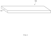
- FIG. 4 is a perspective view of a support in the secondary battery according to the first embodiment of the present invention.
- the support 150 may support the electrode assembly 120 by connecting the plurality of electrode leads 140 to both ends thereof within the pouch 110.
- the support 150 may include a non-conductive material.
- the support 150 may include, for example, heat-dissipating plastic or heat-dissipating resin material.
- the heat-dissipating plastic may specifically include, for example, thermally-conductive plastic.
- the heat-dissipating resin may specifically include, for example, a thermally conductive resin.
- the support 150 may include a support part having certain strength or higher to enable a support function and a coating part applied on an outer surface of the support part so as not to react with an electrolyte.
- the support part may include an epoxy resin, which has mechanical strength for the supporting, has high thermal conductivity, and includes an insulating material
- the coating portion may include, for example, silicone, which has chemical resistance and is an insulating material.
- the support 150 may be provided in the form of a hollow tube.
- the support 150 may be provided, for example, in the shape of a square tube.
- a surface of the support 150, which is in contact with the electrode assembly 120, may provide a square contact surface to more well support the electrode assembly 120.
- one end of the support 150 may be fixed to a lower side of the end of the positive electrode lead 141, and the other end of the support 150 may be fixed to a lower side of the end of the negative electrode lead 142.
- the support 150 may be disposed between the positive electrode 121 and the negative electrode 122. That is, the support 150 may be stacked between the positive electrode 121 and the negative electrode 122 in the form of square plates, which are stacked in one direction.
- the support 150 may, for example, face the positive electrode 121 and the negative electrode 122 with the separator 124 therebetween.
- the support 150 may be made of an insulating material and directly face the positive electrode 121 and the negative electrode 122.
- the support 150 may pass through a central side of the electrode assembly 120.
- the support 150 may pass through the central side of the electrode assembly 120 in the stacking direction. That is, the support 150 may, for example, pass through the electrode assembly 120 in the horizontal direction to support the electrode assembly 120 when the electrodes 123 and the separators 124 are alternately stacked in a vertical direction.
- the support 150 may, for example, transfer heat generated in the electrode assembly 120 to the electrode lead 140. That is, high heat generated at a portion of the electrode assembly 120 around the support 150 may be transferred to the electrode lead 140, and the surroundings may be cooled through heat dissipation that transfers heat to the outside through the electrode lead 140.
- the support 150 may have an accommodation space 151, in which coolant is accommodated, to cool the surroundings. That is, the coolant such as cooling water may be disposed inside the support 150 to cool the high heat generated in the electrode assembly 120 around the support 150.
- the accommodation space 151 of the support 150 may be sealed or connected to a cooling water supply line disposed outside the pouch.
- the support 150 may transfer the heat generated in the electrode assembly 120 to the electrode lead 140 to indirectly cool the surroundings and also may provide the accommodation space 151, in which the coolant is accommodated, to directly cool the surroundings.
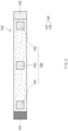
- FIG. 5 is a plan view of the support and a temperature sensor according to the first embodiment of the present invention.
- a temperature sensor 160 may be provided on the support 150 to sense a surrounding temperature.
- the temperature sensor 160 may be disposed, for example, in an outer surface of the support 150.
- the temperature sensor 160 may include a first temperature sensor 161 and a second temperature sensor 162, which are provided at both ends of the support 150, and a third temperature sensor 163 provided at a central portion of the support 150.
- a temperature around the electrode tab 130 or the electrode lead 140 may be sensed through the first temperature sensor 161 and the second temperature sensor 162, and a temperature at the central position of the electrode assembly 120 may be sensed through the third temperature sensor 163.
- temperature monitoring may be easy through the first temperature sensor 161, the second temperature sensor 162, and the third temperature sensor 163 to effectively manage the temperatures.
- the secondary battery 100 may include the support 150 that supports the electrode assembly 120 to firmly support the electrode assembly 120 from use environment such as vibration and impacts, thereby strengthening durability.
- both ends of the support 150 may be connected to the positive electrode lead 141 and the negative electrode lead 142, respectively, and thus, the electrode assembly 120 may be supported more firmly.
- the support 150 may transfer the heat generated in the electrode assembly 120 to the electrode lead 140 to cool the surroundings through the heat dissipation that transfers the heat to the outside through the electrode lead 140.
- the coolant may be accommodated in the support 150 to cool the surroundings.
- the support 150 may be provided with the temperature sensor 160 that senses the surrounding temperature to effectively manage the internal temperature.
- a battery pack may be configured to include the secondary battery 100 according to the first embodiment of the present invention configured as described above.
- the battery pack may include a secondary battery 100 and a pack case that accommodates the secondary battery 100 therein.
- the battery pack may be a cell stack in which the plurality of secondary batteries 100 are stacked and may be accommodated in a pack case.
- FIG. 6 is a plan view illustrating an example of the inside of a secondary battery according to a second embodiment of the present invention
- FIG. 7 is a side cross-sectional view illustrating a main part of the secondary battery according to the second embodiment of the present invention
- FIG. 8 is a perspective view of a support in the secondary battery according to the second embodiment of the present invention.
- a secondary battery 200 includes an electrode assembly 120, a pouch 110 in which the electrode assembly 120 is accommodated, a plurality of electrode leads 140 connected to the electrode assembly 120 to extend to the outside of the pouch 110, and a support 250 connected to the plurality of electrode leads 140 within the pouch.
- the secondary battery 200 according to the second embodiment of the present invention may further include a temperature sensor that senses a temperature.
- the secondary battery 200 according to the second embodiment of the present invention is the same as the secondary battery according to the first embodiment except for a shape of the support 250.
- contents of this embodiment which are duplicated with those according to the forgoing embodiment, will be omitted or briefly described, and also, differences therebetween will be mainly described.
- the electrode assembly 120 may be a chargeable and dischargeable power generation element and may comprise electrodes 123 and separators 124, which are alternately stacked.
- the electrodes 123 may include a positive electrode 121 and a negative electrode 122.
- the electrode assembly 120 may have a structure in which the positive electrode 121/the separator 124/the negative electrode 122 are alternately laminated.
- the positive electrode 121 and the negative electrode 122 may be provided in the shape of square plates and be stacked in one direction and also may face each other with the separator 124 therebetween.
- the electrode assembly 120 may further include an electrode tab 130 provided on an end of the electrode 123.
- the electrode tab 130 may be provided on each electrode 123.
- the electrode tab 130 may include a positive electrode tab 131 provided on an end of the positive electrode 121 and a negative electrode tab 132 provided on an end of the negative electrode 122.
- the positive electrode tab 131 may be provided on an end of one side of the positive electrode 121
- the negative electrode tab 132 may be provided on an end of the other side of the negative electrode 122.
- the pouch 110 may have an accommodation part 111a therein to accommodate the electrode assembly 120 therein.
- the pouch 110 includes a body 111, in which the accommodation part 111a accommodating the electrode assembly 120 is provided, and a sealing part 112 sealed at an edge of the body 111.
- the sealing part 112 may be disposed on an outer circumferential surface of the secondary battery 200 and may be formed through thermal compression.
- the pouch 110 may include an upper case 110a and a lower case 110b, and the sealing part 112 may be formed by sealing outer circumferential surfaces of the upper case 110a and the lower case 110b.
- a portion of the electrode lead 140 which is between the outer circumferential surface of the upper case 110a and the outer circumferential surface of the lower case 110b, may be sealed together with the outer circumferential surfaces of the upper case 110a and the lower case 110b.
- the electrode lead 140 may be fixed to the pouch 110 by the sealing part 112.
- the pouch 110 may include a flexible material.
- the pouch 110 may include a first insulating layer, an aluminum (Al) sheet, and a second insulating layer, which are stacked from the inside to the outside.
- the electrode lead 140 may be provided in plurality, be connected to both sides of the electrode assembly 120, and extend to the outside of the pouch so that the electrode assembly 120 is electrically connected to the outside.
- the plurality of electrode leads 140 may be fixed to the sealing part 112 disposed on the outer circumferential surface of the pouch 110.
- the plurality of electrode leads 140 may include a positive electrode lead 141 connected to the positive electrode 121 and a negative electrode lead 142 connected to the negative electrode 122.
- the positive electrode lead 141 may extend from one side of the electrode assembly 120, and the negative electrode lead 142 may extend from the other side of the electrode assembly 120.
- the positive lead 141 may be electrically connected to the positive electrode 121 through the positive electrode tab 131
- the negative lead 142 may be electrically connected to the negative electrode 122 through the negative electrode tab 132.
- the positive electrode tab 131 may be connected to a first portion of the positive electrode lead 141
- the negative electrode tab 132 may be connected to a first portion of the negative lead 142.
- both ends of the support 150 may be connected to the second portions of the positive lead 141 and the negative lead 142, respectively.
- the first portion may be disposed outside the second portion.
- the plurality of electrode leads 140 may extend in a longitudinal direction of the pouch 110.
- the support 250 may support the electrode assembly 120 by connecting the plurality of electrode leads 140 to both ends thereof within the pouch 110.
- the support 250 may include a non-conductive material.
- the support 250 may include, for example, heat-dissipating plastic or heat-dissipating resin material.
- the heat-dissipating plastic may specifically include, for example, thermally-conductive plastic.
- the heat-dissipating resin may specifically include, for example, a thermally conductive resin.
- the support may include a non-combustible material.
- the support 250 may include a support part having certain strength or higher to enable a support function and a coating part applied on an outer surface of the support part so as not to react with an electrolyte.
- the support part may include an epoxy resin, which has mechanical strength for the supporting, has high thermal conductivity, and includes an insulating material
- the coating portion may include, for example, silicone, which has chemical resistance and is an insulating material.
- the support 250 may have a plate shape.
- the support 250 may be provided, for example, in the shape of a square plate.
- a surface of the support 150 which is in contact with the electrode assembly 120, may provide a square contact surface to more well support the electrode assembly 120.
- the support 250 may have a plurality of through-holes 252.
- the through-holes 252 may be defined to pass in a stacking direction. Thus, lithium ions, etc. may move through the through-holes 252.
- one end of the support 250 may be fixed to a lower side of the end of the positive electrode lead 141, and the other end of the support 250 may be fixed to a lower side of the end of the negative electrode lead 142.
- the support 250 may be disposed between the positive electrode 121 and the negative electrode 122. That is, the support 250 may be stacked between the positive electrode 121 and the negative electrode 122 in the form of square plates, which are stacked in one direction.
- the support 250 may, for example, face the positive electrode 121 and the negative electrode 122 with the separator 124 therebetween.
- the support 250 may be made of an insulating material and directly face the positive electrode 121 and the negative electrode 122.
- the support 250 may pass through a central side of the electrode assembly 120.
- the support 250 may pass through the central side of the electrode assembly 120 in the stacking direction. That is, the support 250 may, for example, pass through the electrode assembly 120 in the horizontal direction to support the electrode assembly 120 when the electrodes 123 and the separators 124 are alternately stacked in a vertical direction.
- the support 250 may transfer heat generated in the electrode assembly 120 to the electrode lead 140. That is, high heat generated at a portion of the electrode assembly 120 around the support 250 may be transferred to the electrode lead 140, and the surrounding may be cooled through heat dissipation that transfers heat to the outside through the electrode lead 140.
Landscapes
- Chemical & Material Sciences (AREA)
- Chemical Kinetics & Catalysis (AREA)
- Electrochemistry (AREA)
- General Chemical & Material Sciences (AREA)
- Engineering & Computer Science (AREA)
- Manufacturing & Machinery (AREA)
- Connection Of Batteries Or Terminals (AREA)
- Secondary Cells (AREA)
- Cell Separators (AREA)
- Telephone Function (AREA)
- Sealing Battery Cases Or Jackets (AREA)
Abstract
Description
- The present application claims the benefit of the priority of
Korean Patent Application No. 10-2022-0082077, filed on July 4, 2022 - The present invention relate to a secondary battery.
- Secondary batteries are rechargeable unlike primarily batteries, and also, the possibility of compact size and high capacity is high. Thus, recently, many studies on secondary batteries are being carried out. As technology development and demands for mobile devices increase, the demands for secondary batteries as energy sources are rapidly increasing.
- Rechargeable batteries are classified into coin type batteries, cylindrical type batteries, prismatic type batteries, and pouch type batteries according to a shape of a battery case. The secondary battery accommodates an electrode assembly and an electrolyte. In such a secondary battery, an electrode assembly mounted in a battery case is a chargeable and dischargeable power generating device having a structure in which an electrode and a separator are stacked.
- The electrode assembly may be approximately classified into a jelly-roll type electrode assembly in which a separator is interposed between a positive electrode and a negative electrode, each of which is provided as the form of a sheet coated with an active material, and then, the positive electrode, the separator, and the negative electrode are wound, a stacked type electrode assembly in which a plurality of positive and negative electrodes with a separator therebetween are sequentially stacked, and a stack/folding type electrode assembly in which stacked type unit cells are wound together with a separation film having a long length.
- Recently, the pouch-type battery in which a stack/folding type electrode assembly is built in a pouch-type battery case provided as an aluminum lamination sheet is attracting much attention due to its low manufacturing cost, small weight, easy shape deformation, and the like, and thus, its usage is gradually increasing.
- Referring to the structure of the pouch cell, an outer appearance of the pouch and a lead may be relatively firmly coupled to each other in a sealed shape. On the other hand, the internal electrode and the lead are coupled to each other by welding between each tab attached to the electrode and the lead. However, the connected portion between the tab and lead, which supports a body of the electrode, may gradually weaken in durability due to use environments such as vibration and impacts by the advancement of technology, in which the tab becoming thinner and the number of mono-cell stacks, which increases due to high capacity.
- That is, the body is supported only by the tab welding between the electrode and the lead without a separate support structure, and thus there is a limitation in durability, resulting from use environments such as the vibration and impacts.
- One aspect of the present invention is to provide a secondary battery capable of firmly supporting an electrode assembly under use environments such vibration and impacts.
- Another aspect of the present invention is to provide a secondary battery capable of effectively managing an internal temperature thereof.
- A secondary battery according to the present invention may include: an electrode assembly in which electrodes and separators are alternatively stacked; a pouch in which the electrode assembly is accommodated; a plurality of electrode leads connected to both side portions of the electrode assembly, respectively, to extend to the outside of the pouch; and a support configured to connect the plurality of electrode leads.
- I addition, a battery pack according to an embodiment of the present invention may include the secondary battery according to an embodiment of the present invention.
- According to the present invention, the support supporting the electrode assembly may be provided to firmly support the electrode assembly under the use environments such as the vibration and impacts, and thus, the durability may be enhanced. Here, both the ends of the support may be connected to the plurality of electrode leads to more firmly support the electrode assembly.
- In addition, the support may transfer the heat generated in the electrode assembly to the electrode lead to cool the surroundings through the heat dissipation, in which the heat is transferred through the electrode lead to the outside.
- In addition, the coolant may be accommodated in the support to cool the surroundings. In addition, the support may be provided with the temperature sensor that senses the surrounding temperature to effectively manage the internal temperature.
-
-
FIG. 1 is a plan view of a secondary battery according to a first embodiment of the present invention. -
FIG. 2 is a plan view illustrating an example of the inside of a secondary battery according to a first embodiment of the present invention. -
FIG. 3 is a side cross-sectional view illustrating a main part of the secondary battery according to the first embodiment of the present invention. -
FIG. 4 is a perspective view of a support in the secondary battery according to the first embodiment of the present invention. -
FIG. 5 is a plan view of the support and a temperature sensor according to the first embodiment of the present invention. -
FIG. 6 is a plan view illustrating an example of the inside of a secondary battery according to a second embodiment of the present invention. -
FIG. 7 is a side cross-sectional view illustrating a main part of the secondary battery according to the second embodiment of the present invention. -
FIG. 8 is a perspective view of a support in the secondary battery according to the second embodiment of the present invention. - The objectives, specific advantages, and novel features of the present invention will become more apparent from the following detailed description taken in conjunction with the accompanying drawings. It should be noted that the reference numerals are added to the components of the drawings in the present specification with the same numerals as possible, even if they are illustrated in other drawings. Also, the present invention may be embodied in different forms and should not be construed as limited to the embodiments set forth herein. In the following description of the present invention, the detailed descriptions of related arts which may unnecessarily obscure the gist of the present invention will be omitted.
-
FIG. 1 is a plan view of a secondary battery according to a first embodiment of the present invention,FIG. 2 is a plan view illustrating an example of the inside of a secondary battery according to the first embodiment of the present invention, andFIG. 3 is a side cross-sectional view illustrating a main part of the secondary battery according to the first embodiment of the present invention. - Referring to
FIGS. 1 to 3 , asecondary battery 100 according to the first embodiment of the present invention includes anelectrode assembly 120, apouch 110 in which theelectrode assembly 120 is accommodated, a plurality of electrode leads 140 connected to theelectrode assembly 120 to extend to the outside of thepouch 110, and asupport 150 connected to the plurality of electrode leads 140 within the pouch. - In addition, the
secondary battery 100 according to the first embodiment of the present invention may further include atemperature sensor 160 that senses a temperature. - In more detail, referring to
FIG. 3 , theelectrode assembly 120 may be a chargeable and dischargeable power generation element and may includeelectrodes 123 andseparators 124, which are alternately stacked. - The
electrodes 123 may include apositive electrode 121 and anegative electrode 122. Here, theelectrode assembly 120 may have a structure in which thepositive electrode 121/theseparator 124/thenegative electrode 122 are alternately laminated. - The
positive electrode 121 and thenegative electrode 122 may be provided in the shape of square plates and be stacked in one direction and also may face each other with theseparator 124 therebetween. - The
positive electrode 121 may include a positive electrode collector and a positive electrode active material stacked on the positive electrode collector. - The positive electrode collector may be made of an aluminum foil.
- The positive electrode active material may include lithium manganese oxide, lithium cobalt oxide, lithium nickel oxide, lithium iron phosphate, or a compound or mixture containing at least one of the above-described materials.
- The
negative electrode 122 may include a negative electrode collector and a negative electrode active material stacked on the negative electrode collector. - The negative electrode collector may be made of, for example, a foil made of a copper (Cu) material.
- The negative active material may be a compound or a mixture containing a graphite-based material.
- The
separator 124 is made of an insulation material to electrically insulate thepositive electrode 121 from thenegative electrode 122. Here, theseparator 124 may be made of a polyolefin-based resin film such as polyethylene or polypropylene having micropores. - The
electrode assembly 120 may further include anelectrode tab 130 provided on an end of theelectrode 123. Here, when the plurality ofelectrodes 123 are provided in theelectrode assembly 120, theelectrode tab 130 may be provided on eachelectrode 123. - The
electrode tab 130 may include apositive electrode tab 131 provided on an end of thepositive electrode 121 and anegative electrode tab 132 provided on an end of thenegative electrode 122. Here, for example, thepositive electrode tab 131 may be provided on an end of one side of thepositive electrode 121, and thenegative electrode tab 132 may be provided on an end of the other side of thenegative electrode 122. - The
pouch 110 may have anaccommodation part 111a therein to accommodate theelectrode assembly 120 therein. - In addition, the
pouch 110 includes abody 111, in which theaccommodation part 111a accommodating theelectrode assembly 120 is provided, and asealing part 112 sealed at an edge of thebody 111. - The sealing
part 112 may be disposed on an outer circumferential surface of thesecondary battery 100 and may be formed through thermal compression. Here, thepouch 110 may include anupper case 110a and alower case 110b, and the sealingpart 112 may be formed by sealing outer circumferential surfaces of theupper case 110a and thelower case 110b. Here, a portion of theelectrode lead 140, which is between the outer circumferential surface of theupper case 110a and the outer circumferential surface of thelower case 110b, may be sealed together with the outer circumferential surfaces of theupper case 110a and thelower case 110b. Thus, theelectrode lead 140 may be fixed to thepouch 110 by the sealingpart 112. - In addition, the
pouch 110 may include a flexible material. Here, thepouch 110 may include a first insulating layer, an aluminum (Al) sheet, and a second insulating layer, which are stacked from the inside to the outside. - The first insulating layer may include an insulating material. Here, the first insulating layer may include a resin material.
- A second insulating coating layer may include an insulating material. Here, the second insulating coating layer may include a nylon layer containing a nylon material and a resin layer containing a resin material.
- The
electrode lead 140 may be provided in plurality, be connected to both sides of theelectrode assembly 120, and extend to the outside of the pouch so that theelectrode assembly 120 is electrically connected to the outside. Here, the plurality of electrode leads 140 may be fixed to the sealingpart 112 disposed on the outer circumferential surface of thepouch 110. - Here, the plurality of electrode leads 140 may include a
positive electrode lead 141 connected to thepositive electrode 121 and anegative electrode lead 142 connected to thenegative electrode 122. - The
positive electrode lead 141 may extend from one side of theelectrode assembly 120, and thenegative electrode lead 142 may extend from the other side of theelectrode assembly 120. In addition, thepositive lead 141 may be electrically connected to thepositive electrode 121 through thepositive electrode tab 131, and thenegative lead 142 may be electrically connected to thenegative electrode 122 through thenegative electrode tab 132. Here, thepositive electrode tab 131 may be connected to a first portion of thepositive electrode lead 141, and thenegative electrode tab 132 may be connected to a first portion of thenegative lead 142. Here, both ends of thesupport 150 may be connected to the second portions of thepositive lead 141 and thenegative lead 142, respectively. Here, the first portion may be disposed outside the second portion. - In addition, the plurality of electrode leads 140 may extend in a longitudinal direction of the
pouch 110. -
FIG. 4 is a perspective view of a support in the secondary battery according to the first embodiment of the present invention. - Referring to
FIGS. 3 and4 , thesupport 150 may support theelectrode assembly 120 by connecting the plurality of electrode leads 140 to both ends thereof within thepouch 110. - In addition, the
support 150 may include a non-conductive material. Here, thesupport 150 may include, for example, heat-dissipating plastic or heat-dissipating resin material. Here, the heat-dissipating plastic may specifically include, for example, thermally-conductive plastic. In addition, the heat-dissipating resin may specifically include, for example, a thermally conductive resin. - The
support 150 may include a support part having certain strength or higher to enable a support function and a coating part applied on an outer surface of the support part so as not to react with an electrolyte. Here, for example, the support part may include an epoxy resin, which has mechanical strength for the supporting, has high thermal conductivity, and includes an insulating material, and the coating portion may include, for example, silicone, which has chemical resistance and is an insulating material. - In addition, the
support 150 may be provided in the form of a hollow tube. Here, thesupport 150 may be provided, for example, in the shape of a square tube. Thus, a surface of thesupport 150, which is in contact with theelectrode assembly 120, may provide a square contact surface to more well support theelectrode assembly 120. - In addition, one end of the
support 150 may be fixed to a lower side of the end of thepositive electrode lead 141, and the other end of thesupport 150 may be fixed to a lower side of the end of thenegative electrode lead 142. - In addition, the
support 150 may be disposed between thepositive electrode 121 and thenegative electrode 122. That is, thesupport 150 may be stacked between thepositive electrode 121 and thenegative electrode 122 in the form of square plates, which are stacked in one direction. Here, thesupport 150 may, for example, face thepositive electrode 121 and thenegative electrode 122 with theseparator 124 therebetween. As another example, thesupport 150 may be made of an insulating material and directly face thepositive electrode 121 and thenegative electrode 122. - Furthermore, the
support 150 may pass through a central side of theelectrode assembly 120. Here, thesupport 150 may pass through the central side of theelectrode assembly 120 in the stacking direction. That is, thesupport 150 may, for example, pass through theelectrode assembly 120 in the horizontal direction to support theelectrode assembly 120 when theelectrodes 123 and theseparators 124 are alternately stacked in a vertical direction. - The
support 150 may, for example, transfer heat generated in theelectrode assembly 120 to theelectrode lead 140. That is, high heat generated at a portion of theelectrode assembly 120 around thesupport 150 may be transferred to theelectrode lead 140, and the surroundings may be cooled through heat dissipation that transfers heat to the outside through theelectrode lead 140. - In addition, as another example, the
support 150 may have anaccommodation space 151, in which coolant is accommodated, to cool the surroundings. That is, the coolant such as cooling water may be disposed inside thesupport 150 to cool the high heat generated in theelectrode assembly 120 around thesupport 150. Here, theaccommodation space 151 of thesupport 150 may be sealed or connected to a cooling water supply line disposed outside the pouch. - In addition, as another example, the
support 150 may transfer the heat generated in theelectrode assembly 120 to theelectrode lead 140 to indirectly cool the surroundings and also may provide theaccommodation space 151, in which the coolant is accommodated, to directly cool the surroundings. -
FIG. 5 is a plan view of the support and a temperature sensor according to the first embodiment of the present invention. - Referring to
FIGS. 3 and5 , atemperature sensor 160 may be provided on thesupport 150 to sense a surrounding temperature. Here, thetemperature sensor 160 may be disposed, for example, in an outer surface of thesupport 150. - In addition, the
temperature sensor 160 may include afirst temperature sensor 161 and asecond temperature sensor 162, which are provided at both ends of thesupport 150, and athird temperature sensor 163 provided at a central portion of thesupport 150. Thus, a temperature around theelectrode tab 130 or theelectrode lead 140 may be sensed through thefirst temperature sensor 161 and thesecond temperature sensor 162, and a temperature at the central position of theelectrode assembly 120 may be sensed through thethird temperature sensor 163. Thus, temperature monitoring may be easy through thefirst temperature sensor 161, thesecond temperature sensor 162, and thethird temperature sensor 163 to effectively manage the temperatures. - The
secondary battery 100 according to the first embodiment of the present invention configured as described above may include thesupport 150 that supports theelectrode assembly 120 to firmly support theelectrode assembly 120 from use environment such as vibration and impacts, thereby strengthening durability. Here, both ends of thesupport 150 may be connected to thepositive electrode lead 141 and thenegative electrode lead 142, respectively, and thus, theelectrode assembly 120 may be supported more firmly. - In addition, the
support 150 may transfer the heat generated in theelectrode assembly 120 to theelectrode lead 140 to cool the surroundings through the heat dissipation that transfers the heat to the outside through theelectrode lead 140. - Furthermore, the coolant may be accommodated in the
support 150 to cool the surroundings. In addition, thesupport 150 may be provided with thetemperature sensor 160 that senses the surrounding temperature to effectively manage the internal temperature. - A battery pack may be configured to include the
secondary battery 100 according to the first embodiment of the present invention configured as described above. - Here, the battery pack may include a
secondary battery 100 and a pack case that accommodates thesecondary battery 100 therein. In addition, the battery pack may be a cell stack in which the plurality ofsecondary batteries 100 are stacked and may be accommodated in a pack case. - Hereinafter, a secondary battery according to a second embodiment of the present invention will be described.
-
FIG. 6 is a plan view illustrating an example of the inside of a secondary battery according to a second embodiment of the present invention,FIG. 7 is a side cross-sectional view illustrating a main part of the secondary battery according to the second embodiment of the present invention, andFIG. 8 is a perspective view of a support in the secondary battery according to the second embodiment of the present invention. - Referring to
FIGS. 6 to 8 , asecondary battery 200 according to the second embodiment of the present invention includes anelectrode assembly 120, apouch 110 in which theelectrode assembly 120 is accommodated, a plurality of electrode leads 140 connected to theelectrode assembly 120 to extend to the outside of thepouch 110, and asupport 250 connected to the plurality of electrode leads 140 within the pouch. In addition, thesecondary battery 200 according to the second embodiment of the present invention may further include a temperature sensor that senses a temperature. - The
secondary battery 200 according to the second embodiment of the present invention is the same as the secondary battery according to the first embodiment except for a shape of thesupport 250. Thus, contents of this embodiment, which are duplicated with those according to the forgoing embodiment, will be omitted or briefly described, and also, differences therebetween will be mainly described. - In more detail, the
electrode assembly 120 may be a chargeable and dischargeable power generation element and may compriseelectrodes 123 andseparators 124, which are alternately stacked. - The
electrodes 123 may include apositive electrode 121 and anegative electrode 122. Here, theelectrode assembly 120 may have a structure in which thepositive electrode 121/theseparator 124/thenegative electrode 122 are alternately laminated. - The
positive electrode 121 and thenegative electrode 122 may be provided in the shape of square plates and be stacked in one direction and also may face each other with theseparator 124 therebetween. - The
electrode assembly 120 may further include anelectrode tab 130 provided on an end of theelectrode 123. Here, when the plurality ofelectrodes 123 are provided in theelectrode assembly 120, theelectrode tab 130 may be provided on eachelectrode 123. - The
electrode tab 130 may include apositive electrode tab 131 provided on an end of thepositive electrode 121 and anegative electrode tab 132 provided on an end of thenegative electrode 122. Here, for example, thepositive electrode tab 131 may be provided on an end of one side of thepositive electrode 121, and thenegative electrode tab 132 may be provided on an end of the other side of thenegative electrode 122. - The
pouch 110 may have anaccommodation part 111a therein to accommodate theelectrode assembly 120 therein. - In addition, the
pouch 110 includes abody 111, in which theaccommodation part 111a accommodating theelectrode assembly 120 is provided, and a sealingpart 112 sealed at an edge of thebody 111. - The sealing
part 112 may be disposed on an outer circumferential surface of thesecondary battery 200 and may be formed through thermal compression. Here, thepouch 110 may include anupper case 110a and alower case 110b, and the sealingpart 112 may be formed by sealing outer circumferential surfaces of theupper case 110a and thelower case 110b. Here, a portion of theelectrode lead 140, which is between the outer circumferential surface of theupper case 110a and the outer circumferential surface of thelower case 110b, may be sealed together with the outer circumferential surfaces of theupper case 110a and thelower case 110b. Thus, theelectrode lead 140 may be fixed to thepouch 110 by the sealingpart 112. - In addition, the
pouch 110 may include a flexible material. Here, thepouch 110 may include a first insulating layer, an aluminum (Al) sheet, and a second insulating layer, which are stacked from the inside to the outside. - The
electrode lead 140 may be provided in plurality, be connected to both sides of theelectrode assembly 120, and extend to the outside of the pouch so that theelectrode assembly 120 is electrically connected to the outside. Here, the plurality of electrode leads 140 may be fixed to the sealingpart 112 disposed on the outer circumferential surface of thepouch 110. - Here, the plurality of electrode leads 140 may include a
positive electrode lead 141 connected to thepositive electrode 121 and anegative electrode lead 142 connected to thenegative electrode 122. - The
positive electrode lead 141 may extend from one side of theelectrode assembly 120, and thenegative electrode lead 142 may extend from the other side of theelectrode assembly 120. In addition, thepositive lead 141 may be electrically connected to thepositive electrode 121 through thepositive electrode tab 131, and thenegative lead 142 may be electrically connected to thenegative electrode 122 through thenegative electrode tab 132. Here, thepositive electrode tab 131 may be connected to a first portion of thepositive electrode lead 141, and thenegative electrode tab 132 may be connected to a first portion of thenegative lead 142. Here, both ends of thesupport 150 may be connected to the second portions of thepositive lead 141 and thenegative lead 142, respectively. Here, the first portion may be disposed outside the second portion. - In addition, the plurality of electrode leads 140 may extend in a longitudinal direction of the
pouch 110. - The
support 250 may support theelectrode assembly 120 by connecting the plurality of electrode leads 140 to both ends thereof within thepouch 110. - In addition, the
support 250 may include a non-conductive material. Here, thesupport 250 may include, for example, heat-dissipating plastic or heat-dissipating resin material. Here, the heat-dissipating plastic may specifically include, for example, thermally-conductive plastic. In addition, the heat-dissipating resin may specifically include, for example, a thermally conductive resin. - Furthermore, the support may include a non-combustible material.
- The
support 250 may include a support part having certain strength or higher to enable a support function and a coating part applied on an outer surface of the support part so as not to react with an electrolyte. Here, for example, the support part may include an epoxy resin, which has mechanical strength for the supporting, has high thermal conductivity, and includes an insulating material, and the coating portion may include, for example, silicone, which has chemical resistance and is an insulating material. - Furthermore, the
support 250 may have a plate shape. Here, thesupport 250 may be provided, for example, in the shape of a square plate. Thus, a surface of thesupport 150, which is in contact with theelectrode assembly 120, may provide a square contact surface to more well support theelectrode assembly 120. Here, thesupport 250 may have a plurality of through-holes 252. Here, the through-holes 252 may be defined to pass in a stacking direction. Thus, lithium ions, etc. may move through the through-holes 252. - In addition, one end of the
support 250 may be fixed to a lower side of the end of thepositive electrode lead 141, and the other end of thesupport 250 may be fixed to a lower side of the end of thenegative electrode lead 142. - In addition, the
support 250 may be disposed between thepositive electrode 121 and thenegative electrode 122. That is, thesupport 250 may be stacked between thepositive electrode 121 and thenegative electrode 122 in the form of square plates, which are stacked in one direction. Here, thesupport 250 may, for example, face thepositive electrode 121 and thenegative electrode 122 with theseparator 124 therebetween. As another example, thesupport 250 may be made of an insulating material and directly face thepositive electrode 121 and thenegative electrode 122. - Furthermore, the
support 250 may pass through a central side of theelectrode assembly 120. Here, thesupport 250 may pass through the central side of theelectrode assembly 120 in the stacking direction. That is, thesupport 250 may, for example, pass through theelectrode assembly 120 in the horizontal direction to support theelectrode assembly 120 when theelectrodes 123 and theseparators 124 are alternately stacked in a vertical direction. - The
support 250 may transfer heat generated in theelectrode assembly 120 to theelectrode lead 140. That is, high heat generated at a portion of theelectrode assembly 120 around thesupport 250 may be transferred to theelectrode lead 140, and the surrounding may be cooled through heat dissipation that transfers heat to the outside through theelectrode lead 140. - While the present invention has been particularly shown and described with reference to exemplary embodiments thereof, it is to be understood that the scope of the present invention is not limited thereto. It will be understood by those of ordinary skill in the art that various changes in form and details may be made therein without departing from the spirit and scope of the present invention.
- Furthermore, the scope of protection of the present invention will be clarified by the appended claims.
-
- 100, 200:
- Secondary battery
- 110:
- Pouch
- 110a:
- Upper case
- 110b:
- Lower case
- 111:
- Body
- 111a:
- Accommodation part
- 112:
- Sealing part
- 120:
- Electrode assembly
- 121:
- Positive electrode
- 122:
- Negative electrode
- 123:
- Electrode
- 124:
- Separator
- 130:
- Electrode tab
- 131:
- Positive electrode tab
- 132:
- Negative electrode tab
- 140:
- Electrode lead
- 141:
- Positive electrode lead
- 142:
- Negative electrode lead
- 150, 250:
- Support
- 151:
- Accommodation space
- 160:
- Temperature sensor
- 161:
- First temperature sensor
- 162:
- Second temperature sensor
- 163:
- Third temperature sensor
- 252:
- Through-hole
Claims (16)
- A secondary battery comprising:an electrode assembly in which electrodes and separators are alternatively stacked;a pouch in which the electrode assembly is accommodated;a plurality of electrode leads connected to both side portions of the electrode assembly, respectively, to extend to the outside of the pouch; anda support configured to connect the plurality of electrode leads.
- The secondary battery of claim 1, wherein the support comprises a non-conductive material.
- The secondary battery of claim 1, wherein the support has an accommodation space in which coolant is accommodated, to cool surroundings.
- The secondary battery of claim 3, wherein the support is provided in the form of a square tube.
- The secondary battery of claim 1, further comprising a temperature sensor configured to sense a surrounding temperature in the support.
- The secondary battery of claim 5, wherein the temperature sensor comprises:a first temperature sensor and a second temperature sensor, which are provided at both ends of the support, respectively; anda third temperature sensor provided at a central portion of the support.
- The secondary battery of claim 1, wherein the support passes through the electrode assembly.
- The secondary battery of claim 1, wherein the electrodes comprise a positive electrode and a negative electrode, andthe plurality of electrode leads comprise a positive electrode lead connected to the positive electrode and a negative electrode lead connected to the negative electrode,wherein the positive electrode lead extends from one side of the electrode assembly, and the negative electrode lead extends from the other side of the electrode assembly, andboth ends of the support are connected to the positive electrode lead and the negative electrode lead, respectively.
- The secondary battery of claim 8, wherein one end of the support is fixed to a lower side of an end of the positive electrode lead, and
the other end of the support is fixed to a lower side of an end of the negative electrode lead. - The secondary battery of claim 8, wherein the positive electrode and the negative electrode are provided in the form of a square plates, which are stacked in one direction, and face each other with the separator therebetween, and
the support is disposed between the positive electrode and the negative electrode. - The secondary battery of claim 8, wherein the electrode assembly further comprises an electrode tab provided on an end of the electrode,wherein the electrode tab comprises a positive electrode tab provided on an end of the positive electrode and a negative electrode tab provided on an end of the negative electrode,the positive electrode lead is electrically connected to the positive electrode through the positive electrode tab,the negative electrode lead is electrically connected to the negative electrode through the negative electrode tab,the positive electrode is connected to a first portion of the positive electrode lead, and the negative electrode tab is connected to a first portion of the negative electrode lead, andboth ends of the support are connected to second portions of the positive electrode lead and the negative electrode lead.
- The secondary battery of claim 1, wherein the plurality of electrode leads are fixed to a sealing part disposed on an outer circumferential surface of the pouch, and
both ends of the support are connected to the plurality of electrode leads to support the electrode assembly. - The secondary battery of claim 1, wherein the support is provided in the form of a plate.
- The secondary battery of claim 13, wherein the support has a plurality of through-holes.
- The secondary battery of claim 1, wherein the support is connected to the plurality of electrode leads within the pouch.
- A battery pack comprising the secondary battery of any one of claims 1 to 15.
Applications Claiming Priority (2)
| Application Number | Priority Date | Filing Date | Title |
|---|---|---|---|
| KR1020220082077A KR102810454B1 (en) | 2022-07-04 | 2022-07-04 | Rechargeable battery |
| PCT/KR2023/009424 WO2024010339A1 (en) | 2022-07-04 | 2023-07-04 | Secondary battery |
Publications (2)
| Publication Number | Publication Date |
|---|---|
| EP4528913A1 true EP4528913A1 (en) | 2025-03-26 |
| EP4528913A4 EP4528913A4 (en) | 2025-10-08 |
Family
ID=89453713
Family Applications (1)
| Application Number | Title | Priority Date | Filing Date |
|---|---|---|---|
| EP23835805.5A Pending EP4528913A4 (en) | 2022-07-04 | 2023-07-04 | SECONDARY BATTERY |
Country Status (7)
| Country | Link |
|---|---|
| US (1) | US12531309B2 (en) |
| EP (1) | EP4528913A4 (en) |
| JP (1) | JP2025523771A (en) |
| KR (1) | KR102810454B1 (en) |
| CN (1) | CN119384769A (en) |
| CA (1) | CA3259482A1 (en) |
| WO (1) | WO2024010339A1 (en) |
Family Cites Families (22)
| Publication number | Priority date | Publication date | Assignee | Title |
|---|---|---|---|---|
| JP4751500B2 (en) * | 2000-06-23 | 2011-08-17 | トヨタ自動車株式会社 | Electrode wound type secondary battery |
| KR100905390B1 (en) | 2006-08-28 | 2009-06-30 | 주식회사 엘지화학 | Pouch type secondary battery improves safety by preventing internal flow of electrode assembly |
| DE102007017024B3 (en) * | 2007-04-11 | 2008-09-25 | Daimler Ag | Battery cell and method for its manufacture and battery |
| JP5380798B2 (en) | 2007-07-06 | 2014-01-08 | 日産自動車株式会社 | Secondary battery |
| KR101073010B1 (en) * | 2010-04-19 | 2011-10-12 | 삼성에스디아이 주식회사 | Secondary battery |
| JP5737289B2 (en) * | 2010-05-26 | 2015-06-17 | 株式会社Gsユアサ | battery |
| KR101256060B1 (en) | 2011-06-02 | 2013-04-18 | 로베르트 보쉬 게엠베하 | Rechargeable battery |
| KR101297858B1 (en) | 2011-09-30 | 2013-08-19 | 주식회사 엘지화학 | Second battery with porous structures and battery Module using the same |
| KR101495294B1 (en) * | 2011-11-08 | 2015-02-25 | 주식회사 엘지화학 | Apparatus for protecting electrode tab and secondary battery including the same |
| JP5719859B2 (en) | 2012-02-29 | 2015-05-20 | 株式会社半導体エネルギー研究所 | Power storage device |
| KR101571774B1 (en) | 2012-06-12 | 2015-11-25 | 주식회사 엘지화학 | Battery Cell of Improved Cooling Efficiency |
| KR101591691B1 (en) | 2013-06-11 | 2016-02-04 | 주식회사 엘지화학 | An electrochemical device and a battery module having improved anti-vibration |
| KR20150045240A (en) | 2013-10-18 | 2015-04-28 | 주식회사 엘지화학 | Battery cell with improved energy density and Battery assembly comprising the same |
| KR102051930B1 (en) | 2016-01-19 | 2020-01-08 | 주식회사 엘지화학 | Battery Cell with Improved Mechanical Rigidity of Outer Sealing Peripheral Part and Battery Pack Comprising the Same |
| KR102083656B1 (en) | 2017-02-02 | 2020-03-02 | 주식회사 엘지화학 | Secontadary battery, and frame for mechanically coupling electrode tap to electrode lead in the secontadary battery |
| KR101999529B1 (en) * | 2017-07-06 | 2019-07-12 | 주식회사 엘지화학 | Pouch-Type Secondary Battery Having Electrode Lead with Couple Notch |
| KR102264635B1 (en) | 2017-11-23 | 2021-06-15 | 주식회사 엘지에너지솔루션 | The Pouch Type Secondary Battery |
| KR102736483B1 (en) | 2018-06-05 | 2024-11-29 | 에스케이온 주식회사 | Pouch type secondary battery and method for manufacturing the same |
| KR102505094B1 (en) * | 2018-06-19 | 2023-03-06 | 주식회사 엘지에너지솔루션 | Secondary battery and secondary-battery-module |
| JP7144221B2 (en) | 2018-07-09 | 2022-09-29 | 株式会社豊田自動織機 | storage module |
| FR3103393B1 (en) | 2019-11-27 | 2022-07-01 | Arkema France | AIR GAS SEPARATION |
| KR102882418B1 (en) | 2019-12-12 | 2025-11-06 | 현대자동차주식회사 | Secondary battery |
-
2022
- 2022-07-04 KR KR1020220082077A patent/KR102810454B1/en active Active
-
2023
- 2023-07-04 WO PCT/KR2023/009424 patent/WO2024010339A1/en not_active Ceased
- 2023-07-04 EP EP23835805.5A patent/EP4528913A4/en active Pending
- 2023-07-04 US US18/877,428 patent/US12531309B2/en active Active
- 2023-07-04 CN CN202380047689.0A patent/CN119384769A/en active Pending
- 2023-07-04 CA CA3259482A patent/CA3259482A1/en active Pending
- 2023-07-04 JP JP2024574799A patent/JP2025523771A/en active Pending
Also Published As
| Publication number | Publication date |
|---|---|
| KR102810454B1 (en) | 2025-05-21 |
| EP4528913A4 (en) | 2025-10-08 |
| US20250174823A1 (en) | 2025-05-29 |
| WO2024010339A1 (en) | 2024-01-11 |
| JP2025523771A (en) | 2025-07-25 |
| US12531309B2 (en) | 2026-01-20 |
| KR20240004036A (en) | 2024-01-11 |
| CN119384769A (en) | 2025-01-28 |
| CA3259482A1 (en) | 2025-04-01 |
Similar Documents
| Publication | Publication Date | Title |
|---|---|---|
| US12592419B2 (en) | Pouch type case and battery pack including the same | |
| EP3285327B1 (en) | Battery module | |
| EP3336957B1 (en) | Battery module, and battery pack and vehicle comprising the same | |
| KR101983391B1 (en) | Cooling Device for Battery Module and Battery Module Assembly having the same | |
| JP2024508505A (en) | Battery module and battery pack containing it | |
| US20120301777A1 (en) | Secondary battery | |
| KR20100113996A (en) | Battery cell of improved thermal stability and medium-large battery module including the same | |
| JP5344237B2 (en) | Assembled battery | |
| US12531309B2 (en) | Pouch-type secondary battery with support for electrode lead | |
| US12451535B2 (en) | Can for secondary battery and secondary battery | |
| US12580241B2 (en) | Electrode assembly and secondary battery comprising the same | |
| KR20170043321A (en) | Battery Module improved heat conductive structure | |
| KR102751361B1 (en) | Secondary battery and a secondary battery module including the same | |
| KR20250024495A (en) | Battery packy and battery pack including the same | |
| WO2026060678A1 (en) | Battery cell, battery apparatus and electrical apparatus | |
| KR101211217B1 (en) | Pouch type secondary battery capable of preventing short between electrode lead |
Legal Events
| Date | Code | Title | Description |
|---|---|---|---|
| STAA | Information on the status of an ep patent application or granted ep patent |
Free format text: STATUS: THE INTERNATIONAL PUBLICATION HAS BEEN MADE |
|
| PUAI | Public reference made under article 153(3) epc to a published international application that has entered the european phase |
Free format text: ORIGINAL CODE: 0009012 |
|
| STAA | Information on the status of an ep patent application or granted ep patent |
Free format text: STATUS: REQUEST FOR EXAMINATION WAS MADE |
|
| 17P | Request for examination filed |
Effective date: 20241219 |
|
| AK | Designated contracting states |
Kind code of ref document: A1 Designated state(s): AL AT BE BG CH CY CZ DE DK EE ES FI FR GB GR HR HU IE IS IT LI LT LU LV MC ME MK MT NL NO PL PT RO RS SE SI SK SM TR |
|
| REG | Reference to a national code |
Ref country code: DE Ref legal event code: R079 Free format text: PREVIOUS MAIN CLASS: H01M0050572000 Ipc: H01M0050105000 |
|
| A4 | Supplementary search report drawn up and despatched |
Effective date: 20250910 |
|
| DAV | Request for validation of the european patent (deleted) | ||
| DAX | Request for extension of the european patent (deleted) | ||
| RIC1 | Information provided on ipc code assigned before grant |
Ipc: H01M 50/105 20210101AFI20250904BHEP Ipc: H01M 10/647 20140101ALI20250904BHEP Ipc: H01M 10/613 20140101ALI20250904BHEP Ipc: H01M 10/48 20060101ALI20250904BHEP Ipc: H01M 10/6556 20140101ALI20250904BHEP Ipc: H01M 10/6567 20140101ALI20250904BHEP Ipc: H01M 50/40 20210101ALI20250904BHEP Ipc: H01M 50/54 20210101ALI20250904BHEP |