EP4528908A1 - Battery module - Google Patents
Battery module Download PDFInfo
- Publication number
- EP4528908A1 EP4528908A1 EP24794686.6A EP24794686A EP4528908A1 EP 4528908 A1 EP4528908 A1 EP 4528908A1 EP 24794686 A EP24794686 A EP 24794686A EP 4528908 A1 EP4528908 A1 EP 4528908A1
- Authority
- EP
- European Patent Office
- Prior art keywords
- cantilever
- connecting bars
- connecting bar
- disposed
- battery module
- Prior art date
- Legal status (The legal status is an assumption and is not a legal conclusion. Google has not performed a legal analysis and makes no representation as to the accuracy of the status listed.)
- Pending
Links
Images

Classifications
-
- G—PHYSICS
- G01—MEASURING; TESTING
- G01R—MEASURING ELECTRIC VARIABLES; MEASURING MAGNETIC VARIABLES
- G01R31/00—Arrangements for testing electric properties; Arrangements for locating electric faults; Arrangements for electrical testing characterised by what is being tested not provided for elsewhere
- G01R31/36—Arrangements for testing, measuring or monitoring the electrical condition of accumulators or electric batteries, e.g. capacity or state of charge [SoC]
- G01R31/382—Arrangements for monitoring battery or accumulator variables, e.g. SoC
- G01R31/3835—Arrangements for monitoring battery or accumulator variables, e.g. SoC involving only voltage measurements
-
- H—ELECTRICITY
- H01—ELECTRIC ELEMENTS
- H01M—PROCESSES OR MEANS, e.g. BATTERIES, FOR THE DIRECT CONVERSION OF CHEMICAL ENERGY INTO ELECTRICAL ENERGY
- H01M10/00—Secondary cells; Manufacture thereof
- H01M10/42—Methods or arrangements for servicing or maintenance of secondary cells or secondary half-cells
- H01M10/425—Structural combination with electronic components, e.g. electronic circuits integrated to the outside of the casing
-
- H—ELECTRICITY
- H01—ELECTRIC ELEMENTS
- H01M—PROCESSES OR MEANS, e.g. BATTERIES, FOR THE DIRECT CONVERSION OF CHEMICAL ENERGY INTO ELECTRICAL ENERGY
- H01M10/00—Secondary cells; Manufacture thereof
- H01M10/42—Methods or arrangements for servicing or maintenance of secondary cells or secondary half-cells
- H01M10/48—Accumulators combined with arrangements for measuring, testing or indicating the condition of cells, e.g. the level or density of the electrolyte
-
- H—ELECTRICITY
- H01—ELECTRIC ELEMENTS
- H01M—PROCESSES OR MEANS, e.g. BATTERIES, FOR THE DIRECT CONVERSION OF CHEMICAL ENERGY INTO ELECTRICAL ENERGY
- H01M50/00—Constructional details or processes of manufacture of the non-active parts of electrochemical cells other than fuel cells, e.g. hybrid cells
- H01M50/50—Current conducting connections for cells or batteries
- H01M50/502—Interconnectors for connecting terminals of adjacent batteries; Interconnectors for connecting cells outside a battery casing
- H01M50/503—Interconnectors for connecting terminals of adjacent batteries; Interconnectors for connecting cells outside a battery casing characterised by the shape of the interconnectors
-
- H—ELECTRICITY
- H01—ELECTRIC ELEMENTS
- H01M—PROCESSES OR MEANS, e.g. BATTERIES, FOR THE DIRECT CONVERSION OF CHEMICAL ENERGY INTO ELECTRICAL ENERGY
- H01M50/00—Constructional details or processes of manufacture of the non-active parts of electrochemical cells other than fuel cells, e.g. hybrid cells
- H01M50/50—Current conducting connections for cells or batteries
- H01M50/502—Interconnectors for connecting terminals of adjacent batteries; Interconnectors for connecting cells outside a battery casing
- H01M50/507—Interconnectors for connecting terminals of adjacent batteries; Interconnectors for connecting cells outside a battery casing comprising an arrangement of two or more busbars within a container structure, e.g. busbar modules
-
- H—ELECTRICITY
- H01—ELECTRIC ELEMENTS
- H01M—PROCESSES OR MEANS, e.g. BATTERIES, FOR THE DIRECT CONVERSION OF CHEMICAL ENERGY INTO ELECTRICAL ENERGY
- H01M50/00—Constructional details or processes of manufacture of the non-active parts of electrochemical cells other than fuel cells, e.g. hybrid cells
- H01M50/50—Current conducting connections for cells or batteries
- H01M50/502—Interconnectors for connecting terminals of adjacent batteries; Interconnectors for connecting cells outside a battery casing
- H01M50/519—Interconnectors for connecting terminals of adjacent batteries; Interconnectors for connecting cells outside a battery casing comprising printed circuit boards [PCB]
-
- H—ELECTRICITY
- H01—ELECTRIC ELEMENTS
- H01M—PROCESSES OR MEANS, e.g. BATTERIES, FOR THE DIRECT CONVERSION OF CHEMICAL ENERGY INTO ELECTRICAL ENERGY
- H01M50/00—Constructional details or processes of manufacture of the non-active parts of electrochemical cells other than fuel cells, e.g. hybrid cells
- H01M50/50—Current conducting connections for cells or batteries
- H01M50/569—Constructional details of current conducting connections for detecting conditions inside cells or batteries, e.g. details of voltage sensing terminals
-
- Y—GENERAL TAGGING OF NEW TECHNOLOGICAL DEVELOPMENTS; GENERAL TAGGING OF CROSS-SECTIONAL TECHNOLOGIES SPANNING OVER SEVERAL SECTIONS OF THE IPC; TECHNICAL SUBJECTS COVERED BY FORMER USPC CROSS-REFERENCE ART COLLECTIONS [XRACs] AND DIGESTS
- Y02—TECHNOLOGIES OR APPLICATIONS FOR MITIGATION OR ADAPTATION AGAINST CLIMATE CHANGE
- Y02E—REDUCTION OF GREENHOUSE GAS [GHG] EMISSIONS, RELATED TO ENERGY GENERATION, TRANSMISSION OR DISTRIBUTION
- Y02E60/00—Enabling technologies; Technologies with a potential or indirect contribution to GHG emissions mitigation
- Y02E60/10—Energy storage using batteries
Definitions
- the present application relates to the technical field of batteries, for example, a battery module.
- a busbar of the integrated bus module is directly disposed on a printed circuit board (PCB), and the PCB supports the busbar to reduce the occupation of space of the module.
- the busbar is connected to the PCB by a collecting sheet, and a voltage collection circuit disposed on the PCB collects a voltage of the busbar by using the collecting sheet to detect the voltage of the battery module.
- the busbar needs to be connected to the PCB by a dedicated collecting sheet. For a busbar that needs to be connected in series and parallel, a structure is still relatively complex.
- the present application provides a battery module.
- the battery module includes multiple cell assemblies, a PCB and a connecting bar assembly.
- a cell assembly includes multiple cells.
- the PCB is etched with a voltage collection circuit.
- the connecting bar assembly includes multiple connecting bars, a connecting bar includes a connecting bar body and a cantilever structure, the cantilever structure is connected to the connecting bar body, the multiple connecting bars of the same connecting bar assembly are disposed in one-to-one correspondence with the multiple cells of the same cell assembly, the connecting bar body of each connecting bar is connected to a positive electrode of a corresponding cell or is connected to a negative electrode of a corresponding cell, cantilever structures of any two adjacent connecting bars are electrically connected, all cantilever structures of the multiple connecting bars are welded to the PCB, and the voltage collection circuit is configured to collect voltages of the cantilever structures.
- the present application provides a battery module.
- the battery module includes a PCB and a connecting bar assembly.
- the PCB is etched with a voltage collection circuit.
- the connecting bar assembly includes multiple connecting bars.
- the connecting bar includes a connecting bar body and a cantilever structure connected to the connecting bar body. Multiple connecting bars of the same connecting bar assembly are disposed in one-to-one correspondence with multiple cells of the same cell assembly.
- the connecting bar body of each connecting bar is connected to a positive electrode of a corresponding cell or a negative electrode of the corresponding cell.
- Cantilever structures of any two adjacent connecting bars are electrically connected so that the multiple cells of the cell assembly are connected in parallel.
- the cantilever structures of the multiple connecting bars are welded to the PCB.
- the voltage collection circuit is configured to collect the voltage of each cantilever structure, thereby implementing the collection of a voltage of the connecting bar. Since two adjacent connecting bars are connected by cantilever structures, the voltage collection circuit directly collects voltages of the cantilever structures so that a collecting sheet does not need to be additionally disposed and a structure is simple.
- connection may refer to “fixedly connected”, “detachably connected”, or “integrated”, may refer to “mechanically connected” or “electrically connected”, or may refer to “connected directly”, “connected indirectly through an intermediary”, or “connected inside two elements” or “an interaction relation between two elements”.
- connection may refer to “fixedly connected”, “detachably connected”, or “integrated”, may refer to “mechanically connected” or “electrically connected”, or may refer to “connected directly”, “connected indirectly through an intermediary”, or “connected inside two elements” or “an interaction relation between two elements”.
- first feature and the second feature may be in direct contact or be in contact via another feature between the two features instead of being in direct contact.
- first feature is described as “on”, “above”, or “over” the second feature
- first feature is right on, above, or over the second feature
- first feature is obliquely on, above, or over the second feature, or the first feature is at a higher level than the second feature.
- the first feature When the first feature is described as “under”, “below”, or “underneath” the second feature, the first feature is right under, below, or underneath the second feature, the first feature is obliquely under, below, or underneath the second feature, or the first feature is at a lower level than the second feature.
- orientations or position relations indicated by terms such as “above”, “below”, “left” and “right” are based on the drawings. These orientations or position relations are intended to facilitate the description and simplify an operation and not to indicate or imply that a device or element referred to must have such particular orientations or must be configured or operated in such particular orientations. Thus, these orientations or position relations are not to be construed as limiting the present application.
- the terms “first” and “second” are used to distinguish between descriptions and have no special meaning.
- a battery module includes multiple cell assemblies, the cell assembly includes multiple cells, and the battery module further includes a PCB 100 and a connecting bar assembly 200, where the PCB 100 is etched with a voltage collection circuit.
- the connecting bar assembly 200 includes multiple connecting bars 210, the connecting bar 210 includes a connecting bar body 211 and a cantilever structure 212, the cantilever structure 212 is connected to the connecting bar body 211, multiple connecting bars 210 of the same connecting bar assembly 200 are disposed in one-to-one correspondence with multiple cells of the same cell assembly, the connecting bar body 211 of each connecting bar 210 is connected to a positive electrode of a corresponding cell or a negative electrode of a corresponding cell, and cantilever structures 212 of any two adjacent connecting bars 210 are electrically connected so that the multiple cells of the cell assembly are connected in parallel.
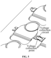
- Cantilever structures 212 of the multiple connecting bars 210 are welded to the PCB 100, the voltage collection circuit is configured to collect the voltage of each cantilever structure 212, and the voltage collection circuit and a voltage collection point are illustrated in FIG. 5 ; thus, the collection of a voltage of the connecting bar 210 is implemented.
- the PCB 100 can play a role in signal collection and transmission and as a carrier of an electronic component, the PCB 100 can improve integration degree, thereby omitting a plastic cover plate in a traditional solution.
- the voltage collection circuit directly collects voltages of the cantilever structures 212 so that no additional collecting sheet is required and the structure is simple.
- the multiple connecting bars 210 of the connecting bar assembly 200 are sequentially disposed in a first direction, one connecting bar 210 includes two cantilever structures 212, and the two cantilever structures 212 are disposed on two sides of the connecting bar body 211 in the first direction, respectively.
- the first direction is the X-Y direction in FIGS. 1 and 3 .
- two cantilever structures 212 are located therebetween.
- the two connecting bars 210 are just connected by the two cantilever structures 212 to simplify the connection structure between the connecting bars 210.
- the battery module further includes a fuse 300 connected between cantilever structures 212 of any two adjacent connecting bars 210 so that the two connecting bars 210 are electrically connected.
- One end of the fuse 300 is connected to one cantilever structure 212 of one of the two connecting bars 210, and the other end of the fuse 300 is connected to one cantilever structure 212 of the other one of the two connecting bars 210 adjacent to the preceding cantilever structure 212.
- the fuse 300 is disposed between cells connected in parallel so that fuse protection can be provided between two cells connected in parallel.
- the cantilever structure 212 includes a cantilever mounting member 2121 and two cantilevers 2122, the two cantilevers 2122 are both disposed on the cantilever mounting member 2121, two fuses 300 are disposed between cantilever structures 212 of any two adjacent connecting bars 210, and the two cantilevers 2122 of the cantilever structure 212 are connected to the two fuses 300 in one-to-one correspondence. In this manner, two fuses 300 can be disposed in parallel between two adjacent connecting bars 210 to improve safety performance.
- the cantilever mounting member 2121 includes a bent portion 2123 and an extending portion 2124, the bent portion 2123 is connected to the connecting bar 210, the extending portion 2124 is connected to the bent portion 2123, the extending portion 2124 extends in the first direction, the bent portion 2123 is disposed at an angle with the extending portion 2124 and is disposed at an angle with a vertical direction, and the first direction is perpendicular to the vertical direction.
- the bent portion 2123 is bent relative to the extending portion 2124 to adapt to the surfaces of the upper ends of the cells having different heights and absorb the common difference of the stacking of the cells. Moreover, the bent portion 2123 can play a role in seismic absorption as a buffer structure.
- the bent portion 2123 and the extending portion 2124 are connected with an arc transition.
- the cantilever structure 212 is made of an elastic material, and the bent portion 2123 and the extending portion 2124 may have elastic deformation so that both the bent portion 2123 and the extending portion 2124 can be bent and the connecting bar 210 can adapt to cells with different heights and at different positions.
- connecting bars 210 located at two ends are end connecting bars, where one cantilever structure 212 of the end connecting bar is connected to another connecting bar 210, and the other cantilever structure 212 of the end connecting bar is not connected to another connecting bar 210.
- temperature collection devices 400 are disposed on at least part of the end connecting bars and are disposed on cantilever structures 212 away from other connecting bars 210 so that the temperature of the connecting bars 210 can be collected by the temperature collection devices 400, that is, the temperature collection device 400 is disposed on the cantilever structure 212 that is not connected to another connecting bar 210, and in this manner, an overall structure of the battery module can be more compact.
- multiple temperature collection devices 400 are provided to collect the temperature at multiple positions through the multiple temperature collection devices 400.
- the PCB 100 has multiple bond pads, and the cantilever structures 212 of the multiple connecting bars 210 are welded to the multiple bond pads in one-to-one correspondence.
- the bond pads are disposed to simplify the disassembly and assembly of the connecting bars 210.
- the bond pads are connected to the voltage collection circuit so that the voltage collection circuit can collect the voltage of each cantilever structure 212.
- the fuse 300 is welded to the bond pad to facilitate the assembly and disassembly of each component.
- the connecting bar body 211 includes a positive electrode connection portion 2111 and a negative electrode connection portion 2112, the positive electrode connection portion 2111 is configured to be connected to the positive electrode of a corresponding cell in one of the multiple cell assemblies, and the negative electrode connection portion 2112 is configured to be connected to the negative electrode of a corresponding cell in another of the multiple cell assemblies.
- any cell assembly includes the same number of multiple cells.
- positive electrodes of cells in a cell assembly located at an intermediate position are connected to connecting bars 210 of one connecting bar assembly 200, and negative electrodes of the cells in the cell assembly located at the intermediate position are connected to connecting bars 210 of another connecting bar assembly 200.
- the battery module further includes two busbars 500, one of the two busbars 500 is connected to negative electrodes of the multiple cells in the first end cell assembly, and the other busbar 500 is connected to positive electrodes of the multiple cells in the second end cell assembly.
- a positive electrode connection hole and a negative electrode connection hole are disposed on the PCB 100, the positive electrode connection portion 2111 is disposed in the positive electrode connection hole, and the negative electrode connection portion 2112 is disposed in the negative electrode connection hole.
- the positive electrode connection hole and the negative electrode connection hole are provided so that both the positive electrode connection portion 2111 and the negative electrode connection portion 2112 pass through the corresponding connection holes to fit snugly around the positive electrode or the negative electrode of the cell, thereby limiting the positive electrode connection portion 2111 and the negative electrode connection portion 2112.
Landscapes
- Chemical & Material Sciences (AREA)
- Chemical Kinetics & Catalysis (AREA)
- Electrochemistry (AREA)
- General Chemical & Material Sciences (AREA)
- Engineering & Computer Science (AREA)
- Manufacturing & Machinery (AREA)
- Microelectronics & Electronic Packaging (AREA)
- Physics & Mathematics (AREA)
- General Physics & Mathematics (AREA)
- Battery Mounting, Suspending (AREA)
- Connection Of Batteries Or Terminals (AREA)
Abstract
Description
- This application claims priority to
Chinese Patent Application No. 202322134282.1 filed with the China National Intellectual Property Administration (CNIPA) on Aug. 9, 2023 - The present application relates to the technical field of batteries, for example, a battery module.
- At present, a voltage sensor and a voltage collection circuit are generally disposed on a busbar to collect a voltage of a battery module.
- The related art provides an integrated bus module. A busbar of the integrated bus module is directly disposed on a printed circuit board (PCB), and the PCB supports the busbar to reduce the occupation of space of the module. In addition, the busbar is connected to the PCB by a collecting sheet, and a voltage collection circuit disposed on the PCB collects a voltage of the busbar by using the collecting sheet to detect the voltage of the battery module. However, in the integrated bus module, the busbar needs to be connected to the PCB by a dedicated collecting sheet. For a busbar that needs to be connected in series and parallel, a structure is still relatively complex.
- The present application provides a battery module. The battery module includes multiple cell assemblies, a PCB and a connecting bar assembly.
- A cell assembly includes multiple cells.
- The PCB is etched with a voltage collection circuit.
- The connecting bar assembly includes multiple connecting bars, a connecting bar includes a connecting bar body and a cantilever structure, the cantilever structure is connected to the connecting bar body, the multiple connecting bars of the same connecting bar assembly are disposed in one-to-one correspondence with the multiple cells of the same cell assembly, the connecting bar body of each connecting bar is connected to a positive electrode of a corresponding cell or is connected to a negative electrode of a corresponding cell, cantilever structures of any two adjacent connecting bars are electrically connected, all cantilever structures of the multiple connecting bars are welded to the PCB, and the voltage collection circuit is configured to collect voltages of the cantilever structures.
- The present application has the beneficial effects described below.
- The present application provides a battery module. The battery module includes a PCB and a connecting bar assembly. The PCB is etched with a voltage collection circuit. The connecting bar assembly includes multiple connecting bars. The connecting bar includes a connecting bar body and a cantilever structure connected to the connecting bar body. Multiple connecting bars of the same connecting bar assembly are disposed in one-to-one correspondence with multiple cells of the same cell assembly. The connecting bar body of each connecting bar is connected to a positive electrode of a corresponding cell or a negative electrode of the corresponding cell. Cantilever structures of any two adjacent connecting bars are electrically connected so that the multiple cells of the cell assembly are connected in parallel. Moreover, the cantilever structures of the multiple connecting bars are welded to the PCB. The voltage collection circuit is configured to collect the voltage of each cantilever structure, thereby implementing the collection of a voltage of the connecting bar. Since two adjacent connecting bars are connected by cantilever structures, the voltage collection circuit directly collects voltages of the cantilever structures so that a collecting sheet does not need to be additionally disposed and a structure is simple.
-
-
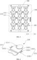
FIG. 1 is a structure diagram of a battery module according to some embodiments of the present application. -
FIG. 2 is an enlarged view of part A ofFIG. 1 . -
FIG. 3 is a top view of a battery module according to some embodiments of the present application. -
FIG. 4 is a structure diagram of a connecting bar according to some embodiments of the present application. -
FIG. 5 is a structure diagram of another battery module according to some embodiments of the present application. -
- 100
- PCB
- 200
- connecting bar assembly
- 210
- connecting bar
- 211
- connecting bar body
- 2111
- positive electrode connection portion
- 2112
- negative electrode connection portion
- 212
- cantilever structure
- 2121
- cantilever mounting member
- 2122
- cantilever
- 2123
- bent portion
- 2124
- extending portion
- 300
- fuse
- 400
- temperature collection device
- 500
- busbar
- In the description of the present application, terms "joined", "connected" and "fixed" are to be understood in a broad sense unless otherwise expressly specified and limited. For example, the term "connected" may refer to "fixedly connected", "detachably connected", or "integrated", may refer to "mechanically connected" or "electrically connected", or may refer to "connected directly", "connected indirectly through an intermediary", or "connected inside two elements" or "an interaction relation between two elements". For those of ordinary skill in the art, specific meanings of the terms in the present application may be understood based on specific situations.
- In the present application, unless otherwise specified and limited, when a first feature is described as being "on" or "below" a second feature, the first feature and the second feature may be in direct contact or be in contact via another feature between the two features instead of being in direct contact. Moreover, when the first feature is described as "on", "above", or "over" the second feature, the first feature is right on, above, or over the second feature, the first feature is obliquely on, above, or over the second feature, or the first feature is at a higher level than the second feature. When the first feature is described as "under", "below", or "underneath" the second feature, the first feature is right under, below, or underneath the second feature, the first feature is obliquely under, below, or underneath the second feature, or the first feature is at a lower level than the second feature.
- In the description of this embodiment, it is to be noted that orientations or position relations indicated by terms such as "above", "below", "left" and "right" are based on the drawings. These orientations or position relations are intended to facilitate the description and simplify an operation and not to indicate or imply that a device or element referred to must have such particular orientations or must be configured or operated in such particular orientations. Thus, these orientations or position relations are not to be construed as limiting the present application. In addition, the terms "first" and "second" are used to distinguish between descriptions and have no special meaning.
- Referring to
FIGS. 1 to 5 , a battery module includes multiple cell assemblies, the cell assembly includes multiple cells, and the battery module further includes aPCB 100 and a connectingbar assembly 200, where thePCB 100 is etched with a voltage collection circuit. The connectingbar assembly 200 includes multiple connectingbars 210, the connectingbar 210 includes a connectingbar body 211 and acantilever structure 212, thecantilever structure 212 is connected to the connectingbar body 211, multiple connectingbars 210 of the same connectingbar assembly 200 are disposed in one-to-one correspondence with multiple cells of the same cell assembly, the connectingbar body 211 of each connectingbar 210 is connected to a positive electrode of a corresponding cell or a negative electrode of a corresponding cell, andcantilever structures 212 of any two adjacent connectingbars 210 are electrically connected so that the multiple cells of the cell assembly are connected in parallel.Cantilever structures 212 of the multiple connectingbars 210 are welded to thePCB 100, the voltage collection circuit is configured to collect the voltage of eachcantilever structure 212, and the voltage collection circuit and a voltage collection point are illustrated inFIG. 5 ; thus, the collection of a voltage of the connectingbar 210 is implemented. ThePCB 100 can play a role in signal collection and transmission and as a carrier of an electronic component, thePCB 100 can improve integration degree, thereby omitting a plastic cover plate in a traditional solution. In addition, since two adjacent connectingbars 210 are connected bycantilever structures 212, the voltage collection circuit directly collects voltages of thecantilever structures 212 so that no additional collecting sheet is required and the structure is simple. - With continued reference to
FIGS. 1 to 4 , the multiple connectingbars 210 of the connectingbar assembly 200 are sequentially disposed in a first direction, one connectingbar 210 includes twocantilever structures 212, and the twocantilever structures 212 are disposed on two sides of the connectingbar body 211 in the first direction, respectively. The first direction is the X-Y direction inFIGS. 1 and3 . In any two adjacent connectingbars 210, twocantilever structures 212 are located therebetween. The two connectingbars 210 are just connected by the twocantilever structures 212 to simplify the connection structure between the connecting bars 210. - With continued reference to
FIGS. 1 to 4 , the battery module further includes afuse 300 connected betweencantilever structures 212 of any two adjacent connectingbars 210 so that the two connectingbars 210 are electrically connected. One end of thefuse 300 is connected to onecantilever structure 212 of one of the two connectingbars 210, and the other end of thefuse 300 is connected to onecantilever structure 212 of the other one of the two connectingbars 210 adjacent to the precedingcantilever structure 212. Thefuse 300 is disposed between cells connected in parallel so that fuse protection can be provided between two cells connected in parallel. - With continued reference to
FIGS. 1 to 4 , thecantilever structure 212 includes acantilever mounting member 2121 and twocantilevers 2122, the twocantilevers 2122 are both disposed on thecantilever mounting member 2121, twofuses 300 are disposed betweencantilever structures 212 of any two adjacent connectingbars 210, and the twocantilevers 2122 of thecantilever structure 212 are connected to the twofuses 300 in one-to-one correspondence. In this manner, twofuses 300 can be disposed in parallel between two adjacent connectingbars 210 to improve safety performance. - With continued reference to
FIGS. 1 to 4 , in a process of assembling the cells, some cells are stacked in a vertical direction, and surfaces of upper ends of multiple stacked cells have different heights due to an effect of a common difference. In this regard, thecantilever mounting member 2121 includes abent portion 2123 and an extendingportion 2124, thebent portion 2123 is connected to the connectingbar 210, the extendingportion 2124 is connected to thebent portion 2123, the extendingportion 2124 extends in the first direction, thebent portion 2123 is disposed at an angle with the extendingportion 2124 and is disposed at an angle with a vertical direction, and the first direction is perpendicular to the vertical direction. In this manner, thebent portion 2123 is bent relative to the extendingportion 2124 to adapt to the surfaces of the upper ends of the cells having different heights and absorb the common difference of the stacking of the cells. Moreover, thebent portion 2123 can play a role in seismic absorption as a buffer structure. Optionally, thebent portion 2123 and the extendingportion 2124 are connected with an arc transition. - Optionally, the
cantilever structure 212 is made of an elastic material, and thebent portion 2123 and the extendingportion 2124 may have elastic deformation so that both thebent portion 2123 and the extendingportion 2124 can be bent and the connectingbar 210 can adapt to cells with different heights and at different positions. - With continued reference to
FIGS. 1 to 4 , in the first direction, among the multiple connectingbars 210 of the connectingbar assembly 200, connectingbars 210 located at two ends are end connecting bars, where onecantilever structure 212 of the end connecting bar is connected to another connectingbar 210, and theother cantilever structure 212 of the end connecting bar is not connected to another connectingbar 210. In this embodiment,temperature collection devices 400 are disposed on at least part of the end connecting bars and are disposed oncantilever structures 212 away from other connectingbars 210 so that the temperature of the connectingbars 210 can be collected by thetemperature collection devices 400, that is, thetemperature collection device 400 is disposed on thecantilever structure 212 that is not connected to another connectingbar 210, and in this manner, an overall structure of the battery module can be more compact. Optionally, multipletemperature collection devices 400 are provided to collect the temperature at multiple positions through the multipletemperature collection devices 400. - With continued reference to
FIGS. 1 to 4 , thePCB 100 has multiple bond pads, and thecantilever structures 212 of the multiple connectingbars 210 are welded to the multiple bond pads in one-to-one correspondence. The bond pads are disposed to simplify the disassembly and assembly of the connecting bars 210. In addition, the bond pads are connected to the voltage collection circuit so that the voltage collection circuit can collect the voltage of eachcantilever structure 212. Thefuse 300 is welded to the bond pad to facilitate the assembly and disassembly of each component. - With continued reference to
FIGS. 1 to 4 , the connectingbar body 211 includes a positiveelectrode connection portion 2111 and a negativeelectrode connection portion 2112, the positiveelectrode connection portion 2111 is configured to be connected to the positive electrode of a corresponding cell in one of the multiple cell assemblies, and the negativeelectrode connection portion 2112 is configured to be connected to the negative electrode of a corresponding cell in another of the multiple cell assemblies. Optionally, any cell assembly includes the same number of multiple cells. Among the cell assemblies, positive electrodes of cells in a cell assembly located at an intermediate position are connected to connectingbars 210 of one connectingbar assembly 200, and negative electrodes of the cells in the cell assembly located at the intermediate position are connected to connectingbars 210 of another connectingbar assembly 200. Cell assemblies located at two ends are a first end cell assembly and a second end cell assembly, respectively, positive electrodes of cells in the first end cell assembly are connected to connectingbars 210 of a connectingbar assembly 200, and negative electrodes of cells in the second end cell assembly are connected to connectingbars 210 of another connectingbar assembly 200. Optionally, the battery module further includes twobusbars 500, one of the twobusbars 500 is connected to negative electrodes of the multiple cells in the first end cell assembly, and theother busbar 500 is connected to positive electrodes of the multiple cells in the second end cell assembly. - With continued reference to
FIGS. 1 to 4 , a positive electrode connection hole and a negative electrode connection hole are disposed on thePCB 100, the positiveelectrode connection portion 2111 is disposed in the positive electrode connection hole, and the negativeelectrode connection portion 2112 is disposed in the negative electrode connection hole. The positive electrode connection hole and the negative electrode connection hole are provided so that both the positiveelectrode connection portion 2111 and the negativeelectrode connection portion 2112 pass through the corresponding connection holes to fit snugly around the positive electrode or the negative electrode of the cell, thereby limiting the positiveelectrode connection portion 2111 and the negativeelectrode connection portion 2112.
Claims (10)
- A battery module, comprising a plurality of cell assemblies, a printed circuit board, PCB, (100), and a connecting bar assembly (200); whereina cell assembly of the plurality of cell assemblies comprises a plurality of cells;the PCB (100) is etched with a voltage collection circuit; andthe connecting bar assembly (200) comprises a plurality of connecting bars (210), wherein a connecting bar (210) of the plurality of connecting bars (210) comprises a connecting bar body (211) and a cantilever structure (212) connected to the connecting bar body (211), the plurality of connecting bars (210) of a same connecting bar assembly (200) are in one-to-one correspondence with the plurality of cells of the cell assembly, the connecting bar body (211) of the connecting bar (210) is connected to a positive electrode of a corresponding cell of the plurality of cells or is connected to a negative electrode of a corresponding cell of the plurality of cells, cantilever structures (212) of any two adjacent connecting bars (210) among the plurality of connecting bars (210) are electrically connected, cantilever structures (212) of the plurality of connecting bars (210) are welded to the PCB (100), and the voltage collection circuit is configured to collect voltages of the cantilever structures (212).
- The battery module according to claim 1, wherein the plurality of connecting bars (210) of the connecting bar assembly (200) are sequentially disposed in a first direction, one of the plurality of connecting bars (210) comprises two cantilever structures (212), and the two cantilever structures (212) are disposed on two sides of the connecting bar body (211) in the first direction, respectively.
- The battery module according to claim 2, further comprising a fuse (300) connected between cantilever structures (212) of two adjacent connecting bars (210) among the plurality of connecting bars (210).
- The battery module according to claim 3, wherein the cantilever structure (212) comprises a cantilever mounting member (2121) and two cantilevers (2122), wherein the two cantilevers (2122) are both disposed on the cantilever mounting member (2121), two fuses (300) are disposed between cantilever structures (212) of two adjacent connecting bars (210) among the plurality of connecting bars (210), and the two cantilevers (2122) of the cantilever structure (212) are connected to the two fuses (300) in one-to-one correspondence.
- The battery module according to claim 2, wherein the cantilever structure (212) comprises a cantilever mounting member (2121) and a cantilever (2122), wherein the cantilever (2122) is disposed on the cantilever mounting member (2121), and the cantilever mounting member (2121) comprises a bent portion (2123) and an extending portion (2124), wherein the bent portion (2123) is connected to the connecting bar (210), the extending portion (2124) is connected to the bent portion (2123), one end of the extending portion (2124) extends in the first direction, the bent portion (2123) is disposed at an angle with the extending portion (2124) and is disposed at an angle with a vertical direction, and the first direction is perpendicular to the vertical direction.
- The battery module according to claim 2, wherein in the first direction, among the plurality of connecting bars (210) of the connecting bar assembly (200), connecting bars (210) located at two ends are end connecting bars, and a temperature collection device (400) is disposed on at least part of the end connecting bars and is disposed on a cantilever structure (212) of the part of the end connecting bars facing away from other connecting bars (210).
- The battery module according to any one of claims 1 to 6, wherein the PCB (100) comprises a plurality of bond pads, and the cantilever structures (212) of the plurality of connecting bars (210) are welded to the plurality of bond pads in one-to-one correspondence.
- The battery module according to any one of claims 1 to 6, wherein the connecting bar body (211) comprises a positive electrode connection portion (2111) and a negative electrode connection portion (2112), wherein the positive electrode connection portion (2111) is configured to be connected to the positive electrode of the corresponding cell in one of the plurality of cell assemblies, and the negative electrode connection portion (2112) is configured to be connected to the negative electrode of the corresponding cell in another one of the plurality of cell assemblies.
- The battery module according to claim 8, wherein a positive electrode connection hole and a negative electrode connection hole are formed on the PCB (100), the positive electrode connection portion (2111) is disposed in the positive electrode connection hole, and the negative electrode connection portion (2112) is disposed in the negative electrode connection hole.
- The battery module according to any one of claims 1 to 6, wherein the cantilever structure (212) is a resilient structure.
Applications Claiming Priority (2)
| Application Number | Priority Date | Filing Date | Title |
|---|---|---|---|
| CN202322134282.1U CN220710568U (en) | 2023-08-09 | 2023-08-09 | Battery module |
| PCT/CN2024/108668 WO2025031223A1 (en) | 2023-08-09 | 2024-07-31 | Battery module |
Publications (2)
| Publication Number | Publication Date |
|---|---|
| EP4528908A1 true EP4528908A1 (en) | 2025-03-26 |
| EP4528908A4 EP4528908A4 (en) | 2025-06-18 |
Family
ID=90448407
Family Applications (1)
| Application Number | Title | Priority Date | Filing Date |
|---|---|---|---|
| EP24794686.6A Pending EP4528908A4 (en) | 2023-08-09 | 2024-07-31 | BATTERY MODULE |
Country Status (4)
| Country | Link |
|---|---|
| EP (1) | EP4528908A4 (en) |
| CN (1) | CN220710568U (en) |
| DE (1) | DE212024000058U1 (en) |
| WO (1) | WO2025031223A1 (en) |
Families Citing this family (1)
| Publication number | Priority date | Publication date | Assignee | Title |
|---|---|---|---|---|
| CN220710568U (en) * | 2023-08-09 | 2024-04-02 | 惠州亿纬锂能股份有限公司 | Battery module |
Family Cites Families (12)
| Publication number | Priority date | Publication date | Assignee | Title |
|---|---|---|---|---|
| JP5998084B2 (en) * | 2013-03-15 | 2016-09-28 | 日立オートモティブシステムズ株式会社 | Power storage module |
| CN205944217U (en) * | 2016-08-12 | 2017-02-08 | 东莞力朗电池科技有限公司 | A bus bar for conductive connection of cylindrical lithium battery pack |
| EP3327825B1 (en) * | 2016-11-25 | 2019-10-02 | Samsung SDI Co., Ltd. | Busbar for a battery system |
| CN207834378U (en) * | 2018-01-31 | 2018-09-07 | 北京国能电池科技股份有限公司 | PCB cylinder manifolds and battery collector-shoe gear |
| CN210200853U (en) * | 2019-07-30 | 2020-03-27 | 福建飞毛腿动力科技有限公司 | Take shockproof busbar of fuse |
| KR102501080B1 (en) * | 2019-11-29 | 2023-02-17 | 삼성에스디아이 주식회사 | Battery pack |
| JP2022173611A (en) * | 2021-05-10 | 2022-11-22 | 矢崎総業株式会社 | Laser beam welding method, welded structure, and bus bar module |
| CN217158574U (en) * | 2022-01-29 | 2022-08-09 | 湖北亿纬动力有限公司 | Busbar, electric core acquisition assembly and battery module |
| WO2023142581A1 (en) * | 2022-01-29 | 2023-08-03 | 湖北亿纬动力有限公司 | Busbar, battery cell acquisition assembly and battery module |
| CN217086672U (en) * | 2022-02-10 | 2022-07-29 | 瑞浦兰钧能源股份有限公司 | Secondary battery module sampling structure |
| CN218351664U (en) * | 2022-09-06 | 2023-01-20 | 南京正力新能电池技术有限公司 | Integrated bank and battery module |
| CN220710568U (en) * | 2023-08-09 | 2024-04-02 | 惠州亿纬锂能股份有限公司 | Battery module |
-
2023
- 2023-08-09 CN CN202322134282.1U patent/CN220710568U/en active Active
-
2024
- 2024-07-31 WO PCT/CN2024/108668 patent/WO2025031223A1/en active Pending
- 2024-07-31 EP EP24794686.6A patent/EP4528908A4/en active Pending
- 2024-07-31 DE DE212024000058.2U patent/DE212024000058U1/en active Active
Also Published As
| Publication number | Publication date |
|---|---|
| WO2025031223A1 (en) | 2025-02-13 |
| CN220710568U (en) | 2024-04-02 |
| EP4528908A4 (en) | 2025-06-18 |
| DE212024000058U1 (en) | 2025-01-28 |
Similar Documents
| Publication | Publication Date | Title |
|---|---|---|
| CN212874701U (en) | Battery module information acquisition device and battery module | |
| CN211320199U (en) | Sampling assembly, battery module, battery pack and device | |
| EP4528908A1 (en) | Battery module | |
| CN114447528B (en) | Busbar and group battery | |
| JP7663553B2 (en) | Voltage detection wires and voltage detection wire modules | |
| CN112332035B (en) | Wire harness isolation plate assembly and assembly method thereof, battery and device | |
| WO2025138468A1 (en) | Cells contact piece, cells contact system and battery pack | |
| JP7820506B2 (en) | Voltage collection structure and battery module having voltage collection structure | |
| CN218782309U (en) | Signal acquisition device and battery module | |
| CN217239557U (en) | Information acquisition system, energy storage equipment and power device applied to battery pack | |
| CN113871786B (en) | Integrated battery module | |
| CN210516851U (en) | Line number isolation plate assembly structure and battery module | |
| JP2004127778A (en) | Fuel cell | |
| CN218677504U (en) | Signal sampling assembly for battery module and battery module | |
| CN219268077U (en) | Multifunctional signal acquisition CCS device | |
| CN118336261A (en) | Battery pack and preparation method | |
| CN212876189U (en) | Module flexible circuit board sampling connection structure | |
| CN112582690A (en) | Flexible circuit board, die-cut substrate, and battery device | |
| CN115911720A (en) | Battery pack and vehicle | |
| CN222214406U (en) | Single cell and battery module | |
| RU2230403C1 (en) | Electrical accumulator battery | |
| CN223347882U (en) | Battery pack and electric equipment | |
| CN220253697U (en) | Busbar and battery module that assembly efficiency is high | |
| CN222601194U (en) | Packaging structure of energy storage device and energy storage device | |
| CN220106810U (en) | Battery device |
Legal Events
| Date | Code | Title | Description |
|---|---|---|---|
| STAA | Information on the status of an ep patent application or granted ep patent |
Free format text: STATUS: UNKNOWN |
|
| STAA | Information on the status of an ep patent application or granted ep patent |
Free format text: STATUS: THE INTERNATIONAL PUBLICATION HAS BEEN MADE |
|
| PUAI | Public reference made under article 153(3) epc to a published international application that has entered the european phase |
Free format text: ORIGINAL CODE: 0009012 |
|
| STAA | Information on the status of an ep patent application or granted ep patent |
Free format text: STATUS: REQUEST FOR EXAMINATION WAS MADE |
|
| 17P | Request for examination filed |
Effective date: 20241031 |
|
| AK | Designated contracting states |
Kind code of ref document: A1 Designated state(s): AL AT BE BG CH CY CZ DE DK EE ES FI FR GB GR HR HU IE IS IT LI LT LU LV MC ME MK MT NL NO PL PT RO RS SE SI SK SM TR |
|
| A4 | Supplementary search report drawn up and despatched |
Effective date: 20250516 |
|
| RIC1 | Information provided on ipc code assigned before grant |
Ipc: G01R 31/3835 20190101ALI20250512BHEP Ipc: H01M 10/48 20060101ALI20250512BHEP Ipc: H01M 10/42 20060101ALI20250512BHEP Ipc: H01M 50/569 20210101ALI20250512BHEP Ipc: H01M 50/503 20210101ALI20250512BHEP Ipc: H01M 50/519 20210101ALI20250512BHEP Ipc: H01M 50/507 20210101AFI20250512BHEP |