EP4528899A1 - Battery module and battery pack including same - Google Patents
Battery module and battery pack including same Download PDFInfo
- Publication number
- EP4528899A1 EP4528899A1 EP23898012.2A EP23898012A EP4528899A1 EP 4528899 A1 EP4528899 A1 EP 4528899A1 EP 23898012 A EP23898012 A EP 23898012A EP 4528899 A1 EP4528899 A1 EP 4528899A1
- Authority
- EP
- European Patent Office
- Prior art keywords
- venting
- battery module
- battery
- module
- frame
- Prior art date
- Legal status (The legal status is an assumption and is not a legal conclusion. Google has not performed a legal analysis and makes no representation as to the accuracy of the status listed.)
- Pending
Links
Images


Classifications
-
- H—ELECTRICITY
- H01—ELECTRIC ELEMENTS
- H01M—PROCESSES OR MEANS, e.g. BATTERIES, FOR THE DIRECT CONVERSION OF CHEMICAL ENERGY INTO ELECTRICAL ENERGY
- H01M50/00—Constructional details or processes of manufacture of the non-active parts of electrochemical cells other than fuel cells, e.g. hybrid cells
- H01M50/30—Arrangements for facilitating escape of gases
- H01M50/35—Gas exhaust passages comprising elongated, tortuous or labyrinth-shaped exhaust passages
- H01M50/358—External gas exhaust passages located on the battery cover or case
-
- H—ELECTRICITY
- H01—ELECTRIC ELEMENTS
- H01M—PROCESSES OR MEANS, e.g. BATTERIES, FOR THE DIRECT CONVERSION OF CHEMICAL ENERGY INTO ELECTRICAL ENERGY
- H01M50/00—Constructional details or processes of manufacture of the non-active parts of electrochemical cells other than fuel cells, e.g. hybrid cells
- H01M50/20—Mountings; Secondary casings or frames; Racks, modules or packs; Suspension devices; Shock absorbers; Transport or carrying devices; Holders
- H01M50/204—Racks, modules or packs for multiple batteries or multiple cells
- H01M50/207—Racks, modules or packs for multiple batteries or multiple cells characterised by their shape
- H01M50/211—Racks, modules or packs for multiple batteries or multiple cells characterised by their shape adapted for pouch cells
-
- H—ELECTRICITY
- H01—ELECTRIC ELEMENTS
- H01M—PROCESSES OR MEANS, e.g. BATTERIES, FOR THE DIRECT CONVERSION OF CHEMICAL ENERGY INTO ELECTRICAL ENERGY
- H01M50/00—Constructional details or processes of manufacture of the non-active parts of electrochemical cells other than fuel cells, e.g. hybrid cells
- H01M50/30—Arrangements for facilitating escape of gases
- H01M50/308—Detachable arrangements, e.g. detachable vent plugs or plug systems
-
- H—ELECTRICITY
- H01—ELECTRIC ELEMENTS
- H01M—PROCESSES OR MEANS, e.g. BATTERIES, FOR THE DIRECT CONVERSION OF CHEMICAL ENERGY INTO ELECTRICAL ENERGY
- H01M50/00—Constructional details or processes of manufacture of the non-active parts of electrochemical cells other than fuel cells, e.g. hybrid cells
- H01M50/30—Arrangements for facilitating escape of gases
- H01M50/383—Flame arresting or ignition-preventing means
-
- H—ELECTRICITY
- H01—ELECTRIC ELEMENTS
- H01M—PROCESSES OR MEANS, e.g. BATTERIES, FOR THE DIRECT CONVERSION OF CHEMICAL ENERGY INTO ELECTRICAL ENERGY
- H01M2220/00—Batteries for particular applications
- H01M2220/20—Batteries in motive systems, e.g. vehicle, ship, plane
-
- Y—GENERAL TAGGING OF NEW TECHNOLOGICAL DEVELOPMENTS; GENERAL TAGGING OF CROSS-SECTIONAL TECHNOLOGIES SPANNING OVER SEVERAL SECTIONS OF THE IPC; TECHNICAL SUBJECTS COVERED BY FORMER USPC CROSS-REFERENCE ART COLLECTIONS [XRACs] AND DIGESTS
- Y02—TECHNOLOGIES OR APPLICATIONS FOR MITIGATION OR ADAPTATION AGAINST CLIMATE CHANGE
- Y02E—REDUCTION OF GREENHOUSE GAS [GHG] EMISSIONS, RELATED TO ENERGY GENERATION, TRANSMISSION OR DISTRIBUTION
- Y02E60/00—Enabling technologies; Technologies with a potential or indirect contribution to GHG emissions mitigation
- Y02E60/10—Energy storage using batteries
Definitions
- the disclosure relates to a battery module and a battery pack including the same, and more particularly, to a battery module having enhanced safety and a battery pack including the same.
- rechargeable secondary batteries have been used as a power source of electric vehicles (EV), hybrid electric vehicles (HEV), and plug-in hybrid electric vehicles (P-HEV) in order to solve air pollution from existing gasoline vehicles that use fossil fuels, and the need for development of secondary batteries has increased.
- EV electric vehicles
- HEV hybrid electric vehicles
- P-HEV plug-in hybrid electric vehicles
- lithium secondary batteries rarely have a memory effect compared to nickel-based secondary batteries, so lithium secondary batteries are spotlighted with advantages that they are freely charged and discharged, have a low self-discharge rate, and a high energy density.
- a lithium secondary battery mainly use lithium-based oxide and carbon material as positive and negative electrode active materials, respectively.
- a lithium secondary battery includes an electrode assembly in which a positive electrode plate and a negative electrode plate coated with the positive electrode active material and the negative electrode active material are disposed with a separator therebetween and an outer case, that is, a battery case, that seals and stores the electrode assembly together with an electrolyte solution.
- lithium secondary batteries may be classified into can-type secondary batteries in which the electrode assembly is built in a metal can and pouch-type secondary batteries in which the electrode assembly is built in a pouch of an aluminum laminate sheet, depending on the shape of the outer case.
- a battery module formed by electrically connecting multiple battery cells is used.
- multiple battery cells are connected to each other in series or parallel to form a battery cell stack, thereby improving capacity and power.
- one or more battery modules may be mounted together with various control and protection systems, such as a battery management system (BMS) and a cooling system, to form a battery pack.
- BMS battery management system
- battery modules including multiple battery cells may be gathered together and installed in medium to large devices, such as automobiles.
- the temperature of battery modules including multiple battery cells or battery packs including these battery modules may increase rapidly and severely as heat from multiple battery cells is added up in a small space.
- high power may be obtained, but it is not easy to remove heat generated by the battery cells during charging and discharging, and thus, the possibility of explosion or ignition increases. When an explosion or ignition occurs, it is necessary to delay the ignition and the spread of occurring flames.
- the disclosure attempts to provide a battery module and a battery pack including the same capable of suppressing or delaying external discharge of flames or the like, while quickly discharging venting gas generated at an early stage, when an event, such as thermal runaway, occurs inside a battery module.
- a battery module includes: a battery cell stack in which a plurality of battery cells are stacked; a module frame storing the battery cell stack; and a venting frame disposed to cover a first surface of the module frame, wherein the venting frame includes a first venting layer disposed to be adjacent to the module frame and including a plurality of first venting passages and a second venting layer disposed outside the first venting layer and including a second venting passage.
- the plurality of first venting passages may be straight flow paths formed in a longitudinal direction of the battery module.
- the second venting passage may be a meandering flow path formed in zigzags throughout the second venting layer.
- the module frame may include at least one vent hole formed in the first surface of the module frame, and the at least one vent hole is connected to at least one first inlet formed in the first venting layer.
- the first venting layer includes at least one first partition separating the plurality of first venting passages from each other.
- the at least one first partition may extend in the longitudinal direction of the battery module.
- the at least one first inlet includes a plurality of first inlets and the plurality of first venting passages each may include a one of the plurality of first inlets and a first outlet disposed opposite to the first inlet.
- the second venting layer may include at least one second inlet formed on one surface in contact with the first venting layer, and the at least one second inlet is connected to each first outlet.
- the second venting passage may include a second outlet formed on a surface located opposite the first venting layer and on an end opposite the second inlet in the longitudinal direction of the battery module.
- the second venting layer may include a plurality of second partitions forming the second venting passage.
- the plurality of second partitions extend in a different direction from the first partition.
- a length of the second venting passage may be longer than a length of each of the first venting passages.
- a battery pack includes one or more of the battery module described above.
- the battery module having improved safety by quickly discharging venting gas generated during ignition inside the battery module and suppressing or delaying the spread of flame may be provided.
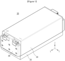
- FIG. 1 is a diagram illustrating a battery module according to an exemplary embodiment of the disclosure
- FIG. 2 is an exploded perspective view of the battery module of FIG. 1 .
- a battery module 100 includes a battery cell stack 110 including one or more battery cells, a module frame 400 storing the battery cell stack 110, and a venting frame 200 disposed to cover one surface of the module frame 400.
- the module frame 400 has open front and rear surfaces and may include an end plate 300 covering the front and rear surfaces. That is, in FIG. 2 , both ends in an X-axis direction are open, and the end plate 300 covers the ends.
- the module frame 400 is shown as having an integrated square tube shape, but without being limited thereto, the module frame 400 may have a shape in which an upper plate is coupled to a U-shaped frame having a lower surface and side walls or a shape in which a lower plate is coupled to an inverted U-shaped frame having an upper surface and side walls.
- a busbar frame 500 accommodated in the module frame 400 may be provided along with the battery cell stack 110.
- the busbar frame 500 includes an upper frame 510 located on the top of the battery cell stack 110, a front frame 520 located on the front of the battery cell stack 110, and a rear surface located on the rear of the battery cell stack 110, and a busbar 540 connected to electrode leads of battery cells constituting the battery cell stack 110 may be mounted on the front frame 520 and the rear frame 530.
- a thermally conductive resin layer (not shown) formed by injecting a thermally conductive resin may be disposed between a lower surface of the battery cell stack 110 and the module frame 400.
- a heat sink 800 may be provided on a side surface of the battery cell stack 110 and may be accommodated together in the module frame 400.
- the venting frame 200 may be disposed on one surface of the module frame 400, e.g., on a lower surface of the module frame 400 in the present exemplary embodiment.
- a configuration of the venting frame 200 will be described in more detail with further reference to FIGS. 3 to 5 .
- FIG. 3 is a cross-sectional view of the venting frame taken along line A-A' of FIG. 2
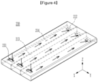
- FIG. 4 is a top view of a first venting layer of the venting frame of FIG. 3
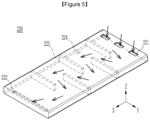
- FIG. 5 is a top view of a second venting layer of the venting frame of FIG. 3 .
- the venting frame 200 may be disposed on one surface of the module frame 400, for example, on the lower surface of the module frame 400 as in the present exemplary embodiment.
- the venting frame 200 may have a dual structure including a first venting layer 210 disposed to be adjacent to the module frame 400 and a second venting layer 220 disposed to be adjacent to the first venting layer 210 and outside the first venting layer 210.
- the venting frame 200 may have a plate shape to cover one surface of the module frame 400 and may be formed to have a dual structure by a plurality of plates.
- the plate forming the venting frame 200 may be formed of a heat-resistant material, such as metal, and may be coupled to the module frame 400 by a method, such as welding, but is not limited thereto and various methods may be used.
- the venting frame 200 includes an inlet and an outlet through which venting gas discharged from the inside of the module frame 400 may flow in and be discharged to the outside and a plurality of passages therebetween.
- a plurality of first venting passages 214 formed in the first venting layer 210 are formed as straight flow paths formed in a longitudinal direction of the battery module 100, that is, in an X-direction in the drawing.
- the plurality of first venting passages 214 are formed to be separated or isolated by at least one first partition 213. That is, the first inlet 211 communicating with the vent hole 410 is formed at one end of each first venting passage 214 separated by the first partition 213, and a first outlet 212 through which the venting gas is discharged is formed on the opposite side, that is, at the other end located on the opposite side in the X-axis direction.
- the venting gas flowing into each first inlet 211 may be discharged through the first outlet 212 via the first venting passage 214, without diffusion or reversal, even within the first venting layer 210.
- the first partition 213 may be formed of the same material as the plate forming the venting frame 200 or may be formed of a material having an equivalent degree of heat resistance.
- the venting gas may be quickly discharged to the second venting layer 220 without flow resistance. That is, by quickly discharging the initially generated venting gas or flames to the next passage, that is, the second venting layer 220, the risk of explosion increasing as the venting gas or flames are accumulated inside the module frame 400 may be prevented.
- At least one second inlet 221 communicating with the first outlet 212 is formed on one surface of the second venting layer 220 facing the first venting layer 210.
- the first outlet 212 and the second inlet 221 are shown as being formed in the same configuration on one plate.
- each venting layer may also be formed to include a separate plate.
- the venting gas flowing in from the first venting layer 210 through the second inlet 221 moves through a second venting passage 224 along the path indicated by the arrow in FIG. 5 .
- the second venting passage 224 may be formed as a meandering flow path having a zigzag or winding shape across the second venting layer 220, as shown in FIG. 5 .
- a second partition 223 parallel to the width direction (a Y direction in the drawing) of the battery module 100 is disposed to alternately contact both side walls, thereby obtaining the second venting passage 224 having a meandering path.
- a path that may increase the movement path of the venting gas within the second venting layer 220 especially, a configuration in which the second venting passage 224 is longer than the first venting passage 214 of the first venting layer 210 may be appropriately adopted.
- the second partition 223 may be formed of the same material as that of the plate forming the venting frame 200 or may be formed of a material having an equivalent degree of heat resistance.
- venting gas may move in zigzags along the meandering flow path even if is it blocked by the partition.
- the venting gas generated at an initial stage may be discharged to the outside of the module frame 400 quickly through the first venting passage 214, thereby eliminating the risk of explosion due to accumulation of venting gas.
- the second venting passage 224 communicating with the first venting passage 214 and having a high-resistance flow path shape discharge of flames generated from the module frame 400 to the outside may be delayed as much as possible, and thus safety may be improved by suppressing flame transfer to adjacent modules.
- One or more battery modules according to the present exemplary embodiment described above may be mounted together with various control and protection systems, such as a battery management system (BMS) and a cooling system to form a battery pack.
- BMS battery management system
- a cooling system to form a battery pack.
- the battery module or battery pack may be applied to various devices. These devices may be applied to transportation units, such as electric bicycles, electric cars, and hybrid vehicles, but are not limited thereto and may be applied to various devices that may use secondary batteries.
- transportation units such as electric bicycles, electric cars, and hybrid vehicles, but are not limited thereto and may be applied to various devices that may use secondary batteries.
Landscapes
- Chemical & Material Sciences (AREA)
- Chemical Kinetics & Catalysis (AREA)
- Electrochemistry (AREA)
- General Chemical & Material Sciences (AREA)
- Battery Mounting, Suspending (AREA)
- Gas Exhaust Devices For Batteries (AREA)
Abstract
Description
- This application claims priority to and the benefit of
Korean Patent Application No. 10-2022-0164567 filed in the Korean Intellectual Property Office on November 30, 2022 - The disclosure relates to a battery module and a battery pack including the same, and more particularly, to a battery module having enhanced safety and a battery pack including the same.
- In modern society, as the use of portable devices, such as mobile phones, laptops, camcorders, and digital cameras, has become routine, technologies in fields related to the above mobile devices have been actively developed. In addition, rechargeable secondary batteries have been used as a power source of electric vehicles (EV), hybrid electric vehicles (HEV), and plug-in hybrid electric vehicles (P-HEV) in order to solve air pollution from existing gasoline vehicles that use fossil fuels, and the need for development of secondary batteries has increased.
- Currently commercialized secondary batteries include nickel cadmium batteries, nickel hydrogen batteries, nickel zinc batteries, and lithium secondary batteries. Among them, lithium secondary batteries rarely have a memory effect compared to nickel-based secondary batteries, so lithium secondary batteries are spotlighted with advantages that they are freely charged and discharged, have a low self-discharge rate, and a high energy density.
- These lithium secondary batteries mainly use lithium-based oxide and carbon material as positive and negative electrode active materials, respectively. A lithium secondary battery includes an electrode assembly in which a positive electrode plate and a negative electrode plate coated with the positive electrode active material and the negative electrode active material are disposed with a separator therebetween and an outer case, that is, a battery case, that seals and stores the electrode assembly together with an electrolyte solution.
- Generally, lithium secondary batteries may be classified into can-type secondary batteries in which the electrode assembly is built in a metal can and pouch-type secondary batteries in which the electrode assembly is built in a pouch of an aluminum laminate sheet, depending on the shape of the outer case.
- In the case of secondary batteries used in small devices, two to three battery cells are arranged, but in the case of secondary batteries used in medium to large devices, such as automobiles, a battery module formed by electrically connecting multiple battery cells is used. In such a battery module, multiple battery cells are connected to each other in series or parallel to form a battery cell stack, thereby improving capacity and power. In addition, one or more battery modules may be mounted together with various control and protection systems, such as a battery management system (BMS) and a cooling system, to form a battery pack.
- Meanwhile, battery modules including multiple battery cells may be gathered together and installed in medium to large devices, such as automobiles. The temperature of battery modules including multiple battery cells or battery packs including these battery modules may increase rapidly and severely as heat from multiple battery cells is added up in a small space. In other words, in the case of battery modules in which multiple battery cells are stacked and battery packs equipped with these battery modules, high power may be obtained, but it is not easy to remove heat generated by the battery cells during charging and discharging, and thus, the possibility of explosion or ignition increases. When an explosion or ignition occurs, it is necessary to delay the ignition and the spread of occurring flames. At the same time, if a venting gas occurring in the battery cell is not quickly discharged at the beginning of thermal runaway, gas accumulates inside the module, further increasing the risk of ignition and explosion, and thus, there is a need to quickly discharge the venting gas in the module to the outside. Therefore, there is a need for a method that may delay flame transfer to adjacent modules, while discharging internal venting gas quickly, when an event, such as thermal runaway, occurs within a battery module or battery pack.
- The disclosure attempts to provide a battery module and a battery pack including the same capable of suppressing or delaying external discharge of flames or the like, while quickly discharging venting gas generated at an early stage, when an event, such as thermal runaway, occurs inside a battery module.
- However, the problems to be solved by the exemplary embodiments of the disclosure are not limited to the above-described problems and may be expanded in various ways within the scope of the technical idea included in the disclosure.
- According to an exemplary embodiment, a battery module includes: a battery cell stack in which a plurality of battery cells are stacked; a module frame storing the battery cell stack; and a venting frame disposed to cover a first surface of the module frame, wherein the venting frame includes a first venting layer disposed to be adjacent to the module frame and including a plurality of first venting passages and a second venting layer disposed outside the first venting layer and including a second venting passage.
- The plurality of first venting passages may be straight flow paths formed in a longitudinal direction of the battery module.
- The second venting passage may be a meandering flow path formed in zigzags throughout the second venting layer.
- The module frame may include at least one vent hole formed in the first surface of the module frame, and the at least one vent hole is connected to at least one first inlet formed in the first venting layer.
- The first venting layer includes at least one first partition separating the plurality of first venting passages from each other.
- The at least one first partition may extend in the longitudinal direction of the battery module.
- The at least one first inlet includes a plurality of first inlets and the plurality of first venting passages each may include a one of the plurality of first inlets and a first outlet disposed opposite to the first inlet.
- The second venting layer may include at least one second inlet formed on one surface in contact with the first venting layer, and the at least one second inlet is connected to each first outlet.
- The second venting passage may include a second outlet formed on a surface located opposite the first venting layer and on an end opposite the second inlet in the longitudinal direction of the battery module.
- The second venting layer may include a plurality of second partitions forming the second venting passage.
- The plurality of second partitions extend in a different direction from the first partition.
- A length of the second venting passage may be longer than a length of each of the first venting passages.
- According to another exemplary embodiment, a battery pack includes one or more of the battery module described above.
- According to exemplary embodiments of the disclosure, the battery module having improved safety by quickly discharging venting gas generated during ignition inside the battery module and suppressing or delaying the spread of flame may be provided.
-
-
FIG. 1 is a diagram illustrating a battery module according to an exemplary embodiment of the disclosure. -
FIG. 2 is an exploded perspective view of the battery module ofFIG. 1 . -
FIG. 3 is a cross-section view of a venting frame taken along line A-A' inFIG. 2 . -
FIG. 4 is a top view of a first venting layer of the venting frame ofFIG. 3 . -
FIG. 5 is a top view of a second venting layer of the venting frame ofFIG. 3 . - Hereinafter, exemplary embodiments of the disclosure will be described in detail with reference to the accompanying drawings to allow those skilled in the art to practice the disclosure. The disclosure may be implemented in various different forms and is not limited to the examples as described herein.
- In the drawings, parts irrelevant to the description are omitted to clearly describe the disclosure, and like reference numerals denote like elements throughout the specification.
- The size and thickness of each component shown in the drawings may be arbitrarily shown for convenience of explanation, and therefore, the disclosure is not necessarily limited to the shown exemplary embodiments in the drawings. In the drawings, the thickness of layers, films, panels, regions, etc., are exaggerated for clarity. Also, in the drawings, the thickness of partial layers and regions may be exaggerated for convenience of explanation.
- It will be understood that when an element, such as a layer, film, region, or substrate is referred to as being "on" another element, it may be directly on the other element or intervening elements may also be present. In contrast, when an element is referred to as being "directly on" another element, there are no intervening elements present. Further, when an element is "above" or "on" the reference portion, it may mean that the element is positioned above or below the reference portion, and it may not necessarily mean that the element is "above" or "on" toward an opposite direction of gravity.
- In addition, unless explicitly described to the contrary, the word "comprise", and variations, such as "comprises" or "comprising", will be understood to imply the inclusion of stated elements but not the exclusion of any other elements.
- Hereinafter, a battery module according to an exemplary embodiment of the disclosure will be described with reference to the drawings.
-
FIG. 1 is a diagram illustrating a battery module according to an exemplary embodiment of the disclosure, andFIG. 2 is an exploded perspective view of the battery module ofFIG. 1 . - Referring to
FIGS. 1 and2 , abattery module 100 according to an exemplary embodiment of the disclosure includes abattery cell stack 110 including one or more battery cells, amodule frame 400 storing thebattery cell stack 110, and aventing frame 200 disposed to cover one surface of themodule frame 400. - The
module frame 400 has open front and rear surfaces and may include anend plate 300 covering the front and rear surfaces. That is, inFIG. 2 , both ends in an X-axis direction are open, and theend plate 300 covers the ends. InFIG. 2 , themodule frame 400 is shown as having an integrated square tube shape, but without being limited thereto, themodule frame 400 may have a shape in which an upper plate is coupled to a U-shaped frame having a lower surface and side walls or a shape in which a lower plate is coupled to an inverted U-shaped frame having an upper surface and side walls. - In addition, a
busbar frame 500 accommodated in themodule frame 400 may be provided along with thebattery cell stack 110. Thebusbar frame 500 includes an upper frame 510 located on the top of thebattery cell stack 110, afront frame 520 located on the front of thebattery cell stack 110, and a rear surface located on the rear of thebattery cell stack 110, and abusbar 540 connected to electrode leads of battery cells constituting thebattery cell stack 110 may be mounted on thefront frame 520 and therear frame 530. - Meanwhile, although not shown, a thermally conductive resin layer (not shown) formed by injecting a thermally conductive resin may be disposed between a lower surface of the
battery cell stack 110 and themodule frame 400. In addition, aheat sink 800 may be provided on a side surface of thebattery cell stack 110 and may be accommodated together in themodule frame 400. - The
venting frame 200 may be disposed on one surface of themodule frame 400, e.g., on a lower surface of themodule frame 400 in the present exemplary embodiment. Hereinafter, a configuration of theventing frame 200 will be described in more detail with further reference toFIGS. 3 to 5 . -
FIG. 3 is a cross-sectional view of the venting frame taken along line A-A' ofFIG. 2 ,FIG. 4 is a top view of a first venting layer of the venting frame ofFIG. 3 , andFIG. 5 is a top view of a second venting layer of the venting frame ofFIG. 3 . - The
venting frame 200 may be disposed on one surface of themodule frame 400, for example, on the lower surface of themodule frame 400 as in the present exemplary embodiment. Theventing frame 200 may have a dual structure including afirst venting layer 210 disposed to be adjacent to themodule frame 400 and asecond venting layer 220 disposed to be adjacent to thefirst venting layer 210 and outside thefirst venting layer 210. In addition, the ventingframe 200 may have a plate shape to cover one surface of themodule frame 400 and may be formed to have a dual structure by a plurality of plates. Here, the plate forming theventing frame 200 may be formed of a heat-resistant material, such as metal, and may be coupled to themodule frame 400 by a method, such as welding, but is not limited thereto and various methods may be used. Theventing frame 200 includes an inlet and an outlet through which venting gas discharged from the inside of themodule frame 400 may flow in and be discharged to the outside and a plurality of passages therebetween. - That is, at least one
vent hole 410 through which venting gas or flame may be discharged when thermal runaway occurs is formed on one surface of themodule frame 400 facing the ventingframe 200. Also, at least onefirst inlet 211 communicating with each of the vent holes 410 is formed on one surface of thefirst venting layer 210 facing one surface of themodule frame 400. The venting gas flowing into thefirst inlet 211 passes through thefirst venting layer 210 and thesecond venting layer 220 and is discharged to the outside. - At this time, a plurality of
first venting passages 214 formed in thefirst venting layer 210 are formed as straight flow paths formed in a longitudinal direction of thebattery module 100, that is, in an X-direction in the drawing. In addition, the plurality offirst venting passages 214 are formed to be separated or isolated by at least onefirst partition 213. That is, thefirst inlet 211 communicating with thevent hole 410 is formed at one end of eachfirst venting passage 214 separated by thefirst partition 213, and afirst outlet 212 through which the venting gas is discharged is formed on the opposite side, that is, at the other end located on the opposite side in the X-axis direction. Accordingly, the venting gas flowing into eachfirst inlet 211 may be discharged through thefirst outlet 212 via thefirst venting passage 214, without diffusion or reversal, even within thefirst venting layer 210. At this time, thefirst partition 213 may be formed of the same material as the plate forming theventing frame 200 or may be formed of a material having an equivalent degree of heat resistance. - In this manner, by forming the
first venting passage 214 included in thefirst venting layer 210 as a straight flow path, the venting gas may be quickly discharged to thesecond venting layer 220 without flow resistance. That is, by quickly discharging the initially generated venting gas or flames to the next passage, that is, thesecond venting layer 220, the risk of explosion increasing as the venting gas or flames are accumulated inside themodule frame 400 may be prevented. - At least one
second inlet 221 communicating with thefirst outlet 212 is formed on one surface of thesecond venting layer 220 facing thefirst venting layer 210. In the present exemplary embodiment, as shown inFIG. 3 , thefirst outlet 212 and thesecond inlet 221 are shown as being formed in the same configuration on one plate. However, without being limited thereto, and each venting layer may also be formed to include a separate plate. - The venting gas flowing in from the
first venting layer 210 through thesecond inlet 221 moves through asecond venting passage 224 along the path indicated by the arrow inFIG. 5 . At this time, thesecond venting passage 224 may be formed as a meandering flow path having a zigzag or winding shape across thesecond venting layer 220, as shown inFIG. 5 . For example, as shown inFIG. 5 , asecond partition 223 parallel to the width direction (a Y direction in the drawing) of thebattery module 100 is disposed to alternately contact both side walls, thereby obtaining thesecond venting passage 224 having a meandering path. However, without being limited thereto, a path that may increase the movement path of the venting gas within thesecond venting layer 220, especially, a configuration in which thesecond venting passage 224 is longer than thefirst venting passage 214 of thefirst venting layer 210 may be appropriately adopted. In this manner, by increasing resistance of the path along which the venting gas moves, discharge of the venting gas to the outside may be suppressed or delayed as much as possible. At this time, thesecond partition 223 may be formed of the same material as that of the plate forming theventing frame 200 or may be formed of a material having an equivalent degree of heat resistance. In addition, in the cross-sectional view ofFIG. 3 , the arrows indicating the path of the venting gas in thesecond venting layer 220 appears as if it is blocked by thesecond partition 223, but this is only a cross-sectional view, and as shown inFIG. 5 , venting gas may move in zigzags along the meandering flow path even if is it blocked by the partition. - In the second venting layer, a
second outlet 222 is formed on the opposite side of the portion in which thesecond inlet 221 is formed, that is, at the opposite end of thebattery module 100 in the longitudinal direction (the X-axis direction). The venting gas moving along thesecond venting passage 224 may be disposed to the outside through thesecond outlet 222. In this manner, by forming thesecond venting passage 224 as a zigzag meandering flow path in thesecond venting layer 220, it is possible to delay as much as possible the venting gas from being discharged to the outside and suppress flames from being discharged to the outside, thereby suppressing the transfer of flames. - According to an exemplary embodiment of the disclosure, when an event, such as thermal runaway occurs in the
battery cell stack 110 inside themodule frame 400, the venting gas generated at an initial stage may be discharged to the outside of themodule frame 400 quickly through thefirst venting passage 214, thereby eliminating the risk of explosion due to accumulation of venting gas. At the same time, by further providing thesecond venting passage 224 communicating with thefirst venting passage 214 and having a high-resistance flow path shape, discharge of flames generated from themodule frame 400 to the outside may be delayed as much as possible, and thus safety may be improved by suppressing flame transfer to adjacent modules. - One or more battery modules according to the present exemplary embodiment described above may be mounted together with various control and protection systems, such as a battery management system (BMS) and a cooling system to form a battery pack.
- The battery module or battery pack may be applied to various devices. These devices may be applied to transportation units, such as electric bicycles, electric cars, and hybrid vehicles, but are not limited thereto and may be applied to various devices that may use secondary batteries.
- The embodiments of the present disclosure have been described in detail, but the scope of the present disclosure is not limited thereto and various variants and modifications by a person skilled in the art using a basic concept of the present disclosure defined in claims also belong to the scope of the present disclosure.
-
- 100: battery module
- 110: battery cell stack
- 200: venting frame
- 210: first venting layer
- 214: first venting passage
- 220: second venting layer
- 224: second venting passage
- 300: end plate
- 400: module frame
- 410: vent hole
- 500: busbar frame
Claims (13)
- A battery module comprising:a battery cell stack in which a plurality of battery cells are stacked;a module frame storing the battery cell stack; anda venting frame disposed to cover a first surface of the module frame,wherein the venting frame includesa first venting layer disposed to be adjacent to the module frame and including a plurality of first venting passages; anda second venting layer disposed outside the first venting layer and including a second venting passage.
- The battery module of claim 1, wherein the plurality of first venting passages are straight flow paths formed in a longitudinal direction of the battery module.
- The battery module of claim 2, wherein the second venting passage is a meandering flow path formed in zigzags throughout the second venting layer.
- The battery module of claim 3, wherein the module frame includes at least one vent hole formed in the first surface of the module frame, and
wherein the at least one vent hole is connected to at least one first inlet formed in the first venting layer. - The battery module of claim 4, wherein the first venting layer includes at least one first partition separating the plurality of first venting passages from each other.
- The battery module of claim 5, wherein the at least one first partition extends in the longitudinal direction of the battery module.
- The battery module of claim 5, wherein the at least one first inlet includes a plurality of first inlets, and
wherein the plurality of first venting passages each include one of the plurality of first inlets and a first outlet disposed opposite to the first inlet. - The battery module of claim 7, wherein the second venting layer includes at least one second inlet formed on one surface in contact with the first venting layer, and
wherein the at least one second inlet is connected to each first outlet. - The battery module of claim 8, wherein the second venting passage includes a second outlet formed on a surface located opposite of the first venting layer and on an end opposite the second inlet in the longitudinal direction of the battery module.
- The battery module of claim 5, wherein the second venting layer includes a plurality of second partitions forming the second venting passage.
- The battery module of claim 10, wherein the plurality of second partitions extend in a different direction from the first partition.
- The battery module of claim 1, wherein a length of the second venting passage is longer than a length of each of the first venting passages.
- A battery pack comprising one or more of the battery module according to claim 1.
Applications Claiming Priority (2)
| Application Number | Priority Date | Filing Date | Title |
|---|---|---|---|
| KR1020220164567A KR20240080846A (en) | 2022-11-30 | 2022-11-30 | Battery module and battery pack including the same |
| PCT/KR2023/013497 WO2024117478A1 (en) | 2022-11-30 | 2023-09-08 | Battery module and battery pack including same |
Publications (2)
| Publication Number | Publication Date |
|---|---|
| EP4528899A1 true EP4528899A1 (en) | 2025-03-26 |
| EP4528899A4 EP4528899A4 (en) | 2026-04-08 |
Family
ID=91324344
Family Applications (1)
| Application Number | Title | Priority Date | Filing Date |
|---|---|---|---|
| EP23898012.2A Pending EP4528899A4 (en) | 2022-11-30 | 2023-09-08 | BATTERY MODULE AND BATTERY PACK SO THAT |
Country Status (5)
| Country | Link |
|---|---|
| EP (1) | EP4528899A4 (en) |
| JP (1) | JP2025521014A (en) |
| KR (1) | KR20240080846A (en) |
| CN (1) | CN119563255A (en) |
| WO (1) | WO2024117478A1 (en) |
Families Citing this family (3)
| Publication number | Priority date | Publication date | Assignee | Title |
|---|---|---|---|---|
| KR20250176417A (en) * | 2024-06-12 | 2025-12-19 | 주식회사 엘지에너지솔루션 | Battery pack case, battery pack and vehicle comprising the same |
| TWI901232B (en) * | 2024-06-26 | 2025-10-11 | 嘉盈鋰源股份有限公司 | Battery module and battery box thereof |
| CN118712643A (en) * | 2024-07-05 | 2024-09-27 | 厦门新能达科技有限公司 | Battery packs and power devices |
Family Cites Families (7)
| Publication number | Priority date | Publication date | Assignee | Title |
|---|---|---|---|---|
| JP2015118811A (en) * | 2013-12-18 | 2015-06-25 | 日産自動車株式会社 | Secondary battery |
| JP6574987B2 (en) * | 2015-02-25 | 2019-09-18 | パナソニックIpマネジメント株式会社 | Battery module |
| KR102030726B1 (en) * | 2015-10-15 | 2019-10-10 | 주식회사 엘지화학 | Battery Pack |
| WO2018123573A1 (en) * | 2016-12-27 | 2018-07-05 | パナソニックIpマネジメント株式会社 | Battery module |
| KR102033101B1 (en) * | 2017-09-27 | 2019-10-16 | 주식회사 엘지화학 | Battery module, battery pack and vehicle comprising the same |
| WO2022203291A1 (en) * | 2021-03-22 | 2022-09-29 | 주식회사 엘지에너지솔루션 | Battery module and battery pack including same |
| KR20220131834A (en) * | 2021-03-22 | 2022-09-29 | 주식회사 엘지에너지솔루션 | Battery module and battery pack including same |
-
2022
- 2022-11-30 KR KR1020220164567A patent/KR20240080846A/en active Pending
-
2023
- 2023-09-08 WO PCT/KR2023/013497 patent/WO2024117478A1/en not_active Ceased
- 2023-09-08 EP EP23898012.2A patent/EP4528899A4/en active Pending
- 2023-09-08 CN CN202380053178.XA patent/CN119563255A/en active Pending
- 2023-09-08 JP JP2024573819A patent/JP2025521014A/en active Pending
Also Published As
| Publication number | Publication date |
|---|---|
| WO2024117478A1 (en) | 2024-06-06 |
| KR20240080846A (en) | 2024-06-07 |
| CN119563255A (en) | 2025-03-04 |
| JP2025521014A (en) | 2025-07-04 |
| EP4528899A4 (en) | 2026-04-08 |
Similar Documents
| Publication | Publication Date | Title |
|---|---|---|
| EP4170792A1 (en) | Battery module and battery pack including same | |
| EP3136497B1 (en) | Battery module including water cooling structure | |
| EP4528899A1 (en) | Battery module and battery pack including same | |
| CN115039280B (en) | Battery pack and device including the battery pack | |
| CN115066795B (en) | Battery pack and device including the battery pack | |
| EP4404361A1 (en) | Battery pack and device including same | |
| EP4181275B1 (en) | Battery module and battery pack including same | |
| KR102949002B1 (en) | Battery module and battery pack including the same | |
| CN222029271U (en) | Battery module and battery pack including the same | |
| KR20220103348A (en) | Battery module and battery pack including the same | |
| EP4170793B1 (en) | Battery module and battery pack including same | |
| JP2025186453A (en) | Battery module and battery pack including same | |
| CN118044046A (en) | Battery pack and device including the battery pack | |
| EP4044325A1 (en) | Battery module and battery pack comprising same | |
| EP4579868A1 (en) | Battery pack and device comprising same | |
| JP7708497B2 (en) | Battery pack and device including same | |
| KR20210072999A (en) | Battery Pack Having High Energy Density And High-Efficiency of radiating heat | |
| KR20230040125A (en) | Battery module and battery pack including the same | |
| EP4664606A1 (en) | Battery pack and device including same | |
| KR102957340B1 (en) | Battery pack and device including the same | |
| EP4625666A1 (en) | Device including battery pack | |
| EP4712246A1 (en) | Battery pack and device including same | |
| US20230261307A1 (en) | Battery pack and device including the same | |
| US20240136641A1 (en) | Battery pack and device including the same | |
| KR20220129324A (en) | Battery module and battery pack including same |
Legal Events
| Date | Code | Title | Description |
|---|---|---|---|
| STAA | Information on the status of an ep patent application or granted ep patent |
Free format text: STATUS: THE INTERNATIONAL PUBLICATION HAS BEEN MADE |
|
| PUAI | Public reference made under article 153(3) epc to a published international application that has entered the european phase |
Free format text: ORIGINAL CODE: 0009012 |
|
| STAA | Information on the status of an ep patent application or granted ep patent |
Free format text: STATUS: REQUEST FOR EXAMINATION WAS MADE |
|
| 17P | Request for examination filed |
Effective date: 20241214 |
|
| AK | Designated contracting states |
Kind code of ref document: A1 Designated state(s): AL AT BE BG CH CY CZ DE DK EE ES FI FR GB GR HR HU IE IS IT LI LT LU LV MC ME MK MT NL NO PL PT RO RS SE SI SK SM TR |
|
| DAV | Request for validation of the european patent (deleted) | ||
| DAX | Request for extension of the european patent (deleted) | ||
| A4 | Supplementary search report drawn up and despatched |
Effective date: 20260311 |
|
| RIC1 | Information provided on ipc code assigned before grant |
Ipc: H01M 50/358 20210101AFI20260305BHEP Ipc: H01M 50/383 20210101ALI20260305BHEP Ipc: H01M 50/211 20210101ALI20260305BHEP Ipc: H01M 50/30 20210101ALI20260305BHEP Ipc: H01M 50/308 20210101ALI20260305BHEP Ipc: H01M 50/35 20210101ALI20260305BHEP Ipc: H01M 50/367 20210101ALI20260305BHEP |