EP4528898A1 - Battery module and method for manufacturing battery module - Google Patents
Battery module and method for manufacturing battery module Download PDFInfo
- Publication number
- EP4528898A1 EP4528898A1 EP23824205.1A EP23824205A EP4528898A1 EP 4528898 A1 EP4528898 A1 EP 4528898A1 EP 23824205 A EP23824205 A EP 23824205A EP 4528898 A1 EP4528898 A1 EP 4528898A1
- Authority
- EP
- European Patent Office
- Prior art keywords
- barriers
- end portion
- barrier
- housing
- hollow space
- Prior art date
- Legal status (The legal status is an assumption and is not a legal conclusion. Google has not performed a legal analysis and makes no representation as to the accuracy of the status listed.)
- Pending
Links
Images



Classifications
-
- H—ELECTRICITY
- H01—ELECTRIC ELEMENTS
- H01M—PROCESSES OR MEANS, e.g. BATTERIES, FOR THE DIRECT CONVERSION OF CHEMICAL ENERGY INTO ELECTRICAL ENERGY
- H01M50/00—Constructional details or processes of manufacture of the non-active parts of electrochemical cells other than fuel cells, e.g. hybrid cells
- H01M50/20—Mountings; Secondary casings or frames; Racks, modules or packs; Suspension devices; Shock absorbers; Transport or carrying devices; Holders
- H01M50/204—Racks, modules or packs for multiple batteries or multiple cells
- H01M50/207—Racks, modules or packs for multiple batteries or multiple cells characterised by their shape
- H01M50/211—Racks, modules or packs for multiple batteries or multiple cells characterised by their shape adapted for pouch cells
-
- H—ELECTRICITY
- H01—ELECTRIC ELEMENTS
- H01M—PROCESSES OR MEANS, e.g. BATTERIES, FOR THE DIRECT CONVERSION OF CHEMICAL ENERGY INTO ELECTRICAL ENERGY
- H01M10/00—Secondary cells; Manufacture thereof
- H01M10/60—Heating or cooling; Temperature control
- H01M10/64—Heating or cooling; Temperature control characterised by the shape of the cells
- H01M10/647—Prismatic or flat cells, e.g. pouch cells
-
- H—ELECTRICITY
- H01—ELECTRIC ELEMENTS
- H01M—PROCESSES OR MEANS, e.g. BATTERIES, FOR THE DIRECT CONVERSION OF CHEMICAL ENERGY INTO ELECTRICAL ENERGY
- H01M10/00—Secondary cells; Manufacture thereof
- H01M10/60—Heating or cooling; Temperature control
- H01M10/65—Means for temperature control structurally associated with the cells
- H01M10/658—Means for temperature control structurally associated with the cells by thermal insulation or shielding
-
- H—ELECTRICITY
- H01—ELECTRIC ELEMENTS
- H01M—PROCESSES OR MEANS, e.g. BATTERIES, FOR THE DIRECT CONVERSION OF CHEMICAL ENERGY INTO ELECTRICAL ENERGY
- H01M50/00—Constructional details or processes of manufacture of the non-active parts of electrochemical cells other than fuel cells, e.g. hybrid cells
- H01M50/20—Mountings; Secondary casings or frames; Racks, modules or packs; Suspension devices; Shock absorbers; Transport or carrying devices; Holders
- H01M50/233—Mountings; Secondary casings or frames; Racks, modules or packs; Suspension devices; Shock absorbers; Transport or carrying devices; Holders characterised by physical properties of casings or racks, e.g. dimensions
- H01M50/24—Mountings; Secondary casings or frames; Racks, modules or packs; Suspension devices; Shock absorbers; Transport or carrying devices; Holders characterised by physical properties of casings or racks, e.g. dimensions adapted for protecting batteries from their environment, e.g. from corrosion
-
- H—ELECTRICITY
- H01—ELECTRIC ELEMENTS
- H01M—PROCESSES OR MEANS, e.g. BATTERIES, FOR THE DIRECT CONVERSION OF CHEMICAL ENERGY INTO ELECTRICAL ENERGY
- H01M50/00—Constructional details or processes of manufacture of the non-active parts of electrochemical cells other than fuel cells, e.g. hybrid cells
- H01M50/20—Mountings; Secondary casings or frames; Racks, modules or packs; Suspension devices; Shock absorbers; Transport or carrying devices; Holders
- H01M50/289—Mountings; Secondary casings or frames; Racks, modules or packs; Suspension devices; Shock absorbers; Transport or carrying devices; Holders characterised by spacing elements or positioning means within frames, racks or packs
-
- H—ELECTRICITY
- H01—ELECTRIC ELEMENTS
- H01M—PROCESSES OR MEANS, e.g. BATTERIES, FOR THE DIRECT CONVERSION OF CHEMICAL ENERGY INTO ELECTRICAL ENERGY
- H01M50/00—Constructional details or processes of manufacture of the non-active parts of electrochemical cells other than fuel cells, e.g. hybrid cells
- H01M50/20—Mountings; Secondary casings or frames; Racks, modules or packs; Suspension devices; Shock absorbers; Transport or carrying devices; Holders
- H01M50/289—Mountings; Secondary casings or frames; Racks, modules or packs; Suspension devices; Shock absorbers; Transport or carrying devices; Holders characterised by spacing elements or positioning means within frames, racks or packs
- H01M50/291—Mountings; Secondary casings or frames; Racks, modules or packs; Suspension devices; Shock absorbers; Transport or carrying devices; Holders characterised by spacing elements or positioning means within frames, racks or packs characterised by their shape
-
- H—ELECTRICITY
- H01—ELECTRIC ELEMENTS
- H01M—PROCESSES OR MEANS, e.g. BATTERIES, FOR THE DIRECT CONVERSION OF CHEMICAL ENERGY INTO ELECTRICAL ENERGY
- H01M50/00—Constructional details or processes of manufacture of the non-active parts of electrochemical cells other than fuel cells, e.g. hybrid cells
- H01M50/30—Arrangements for facilitating escape of gases
- H01M50/35—Gas exhaust passages comprising elongated, tortuous or labyrinth-shaped exhaust passages
- H01M50/358—External gas exhaust passages located on the battery cover or case
-
- H—ELECTRICITY
- H01—ELECTRIC ELEMENTS
- H01M—PROCESSES OR MEANS, e.g. BATTERIES, FOR THE DIRECT CONVERSION OF CHEMICAL ENERGY INTO ELECTRICAL ENERGY
- H01M50/00—Constructional details or processes of manufacture of the non-active parts of electrochemical cells other than fuel cells, e.g. hybrid cells
- H01M50/50—Current conducting connections for cells or batteries
- H01M50/502—Interconnectors for connecting terminals of adjacent batteries; Interconnectors for connecting cells outside a battery casing
- H01M50/507—Interconnectors for connecting terminals of adjacent batteries; Interconnectors for connecting cells outside a battery casing comprising an arrangement of two or more busbars within a container structure, e.g. busbar modules
-
- H—ELECTRICITY
- H01—ELECTRIC ELEMENTS
- H01M—PROCESSES OR MEANS, e.g. BATTERIES, FOR THE DIRECT CONVERSION OF CHEMICAL ENERGY INTO ELECTRICAL ENERGY
- H01M50/00—Constructional details or processes of manufacture of the non-active parts of electrochemical cells other than fuel cells, e.g. hybrid cells
- H01M50/50—Current conducting connections for cells or batteries
- H01M50/502—Interconnectors for connecting terminals of adjacent batteries; Interconnectors for connecting cells outside a battery casing
- H01M50/509—Interconnectors for connecting terminals of adjacent batteries; Interconnectors for connecting cells outside a battery casing characterised by the type of connection, e.g. mixed connections
- H01M50/51—Connection only in series
-
- H—ELECTRICITY
- H01—ELECTRIC ELEMENTS
- H01M—PROCESSES OR MEANS, e.g. BATTERIES, FOR THE DIRECT CONVERSION OF CHEMICAL ENERGY INTO ELECTRICAL ENERGY
- H01M50/00—Constructional details or processes of manufacture of the non-active parts of electrochemical cells other than fuel cells, e.g. hybrid cells
- H01M50/50—Current conducting connections for cells or batteries
- H01M50/543—Terminals
- H01M50/547—Terminals characterised by the disposition of the terminals on the cells
- H01M50/548—Terminals characterised by the disposition of the terminals on the cells on opposite sides of the cell
-
- H—ELECTRICITY
- H01—ELECTRIC ELEMENTS
- H01M—PROCESSES OR MEANS, e.g. BATTERIES, FOR THE DIRECT CONVERSION OF CHEMICAL ENERGY INTO ELECTRICAL ENERGY
- H01M50/00—Constructional details or processes of manufacture of the non-active parts of electrochemical cells other than fuel cells, e.g. hybrid cells
- H01M50/50—Current conducting connections for cells or batteries
- H01M50/572—Means for preventing undesired use or discharge
- H01M50/584—Means for preventing undesired use or discharge for preventing incorrect connections inside or outside the batteries
- H01M50/59—Means for preventing undesired use or discharge for preventing incorrect connections inside or outside the batteries characterised by the protection means
-
- Y—GENERAL TAGGING OF NEW TECHNOLOGICAL DEVELOPMENTS; GENERAL TAGGING OF CROSS-SECTIONAL TECHNOLOGIES SPANNING OVER SEVERAL SECTIONS OF THE IPC; TECHNICAL SUBJECTS COVERED BY FORMER USPC CROSS-REFERENCE ART COLLECTIONS [XRACs] AND DIGESTS
- Y02—TECHNOLOGIES OR APPLICATIONS FOR MITIGATION OR ADAPTATION AGAINST CLIMATE CHANGE
- Y02E—REDUCTION OF GREENHOUSE GAS [GHG] EMISSIONS, RELATED TO ENERGY GENERATION, TRANSMISSION OR DISTRIBUTION
- Y02E60/00—Enabling technologies; Technologies with a potential or indirect contribution to GHG emissions mitigation
- Y02E60/10—Energy storage using batteries
Definitions
- the present invention relates to a battery module and a manufacturing method of a battery module, and more particularly, to a battery module and a manufacturing method of a battery module in which heat transfer between battery cells is delayed or prevented and manufacturing costs are reduced.
- a secondary battery refers to a battery that may be charged and discharged, unlike primary batteries that cannot be recharged. These secondary batteries are used in small, high-tech electronic devices such as mobile phones, PDAs and laptop computers as well as in energy storage systems (ESS), electric vehicles (EV) or hybrid electric vehicles (HEV) as a power source.
- ESS energy storage systems
- EV electric vehicles
- HEV hybrid electric vehicles
- a battery module refers to a device in which a plurality of secondary batteries (referred to as “battery cells” hereinafter) is connected in series or parallel.
- FIG. 1 is a plan view illustrating a conventional battery module.
- a conventional battery module 1 may include a housing 2, a busbar 3 and a battery cell 4.
- a plurality of battery cells 4 may be electrically connected to the busbar 3.
- heat, flame, etc. may be transferred/propagated, thereby propagating the thermal runaway phenomenon to the battery cell 4 adjacent to the battery cell 4 shown at the upper end of the drawing.
- heat, flame, etc. may be transferred/propagated through the busbar 3 or the space where the busbar 3 is installed, as shown by the dashed-dotted arrow A such that the thermal runaway phenomenon is propagated even to the battery cell that is not adjacent to the battery cell 4 shown at the upper end of the drawing.
- the thermal runaway phenomenon can spread more rapidly to non-adjacent battery cells 300, and the possibility of the battery module igniting or exploding increases.
- a pair of battery cells 4 that are not adjacent to each other have a larger potential difference than a pair of adjacent battery cells 4 such that the possibility of the problem of short circuit in the battery cell 4 increases due to the thermal runaway phenomenon spreading more rapidly to non-adjacent battery cells 300 having a large potential difference.
- Korean Patent Application Publication No. 10-2022-0014117 discloses a battery module that includes an endothermic firewall capable of controlling the heat transfer phenomenon caused by a battery fire, wherein an endothermic firewall is interposed between a plurality of secondary battery cells accommodated in the battery module.
- Patent Document 0001 Korean Patent Application Publication No. 10-2022-0014117
- the present invention provides a battery module including a housing 100, a plurality of busbars 200, a plurality of battery cells 300 and one or more barriers 400.
- the housing 100 may be provided with a hollow space S therein.
- the plurality of busbars 200 may be installed at one end portion and the other end portion in the first direction of the hollow space S.
- the plurality of battery cells 300 are arranged in the hollow space S side by side in a second direction that intersects the first direction and upward and downward directions.
- Each of the plurality of battery cells 300 may include a body 310 and a pair of electrodes 320 and 330.
- the body 310 may be disposed at a center portion in the first direction of the hollow space S.
- the pair of electrodes 320 and 330 may protrude from the body 310 toward one side and the other side of the first direction.
- the one or more barriers 400 may include a first barrier 400a or a second barrier 400b.
- the first barrier 400a may extend to one side of the first direction and is in contact with the first sidewall 120, thereby partitioning, in the second direction, the one end portion in the first direction of the hollow space S.
- the first barrier 400a may be at least partially separated from the second sidewall 130.
- the second barrier 400b may extend to the other side of the first direction and is in contact with the second sidewall 130, thereby partitioning, in the second direction, the other end portion in the first direction of the hollow space S.
- the plurality of busbars 200 may include one side busbar 200a and the other side busbar 200b.
- the one side busbar 200a and the other side busbar 200b may be installed: at one side and other side of the second direction of one side in the first direction of the first barrier 400a, respectively, adjacent to the first barrier 400a with the first barrier 400a therebetween while physically separated from each other; or at the one side and the other side of the second direction of other side in the first direction of the second barrier 400b, respectively, adjacent to the second barrier 400b with the second barrier 400b therebetween while physically separated from each other.
- the plurality of battery cells 300 may include one side battery cell 300a and the other side battery cell 300b.
- the one side battery cell 300a and the other side battery cell 300b may be disposed: at one side and other side in the second direction of the first barrier 400a, respectively, adjacent to the first barrier 400a; or at one side and other side in the second direction of the second barrier 400b, respectively, adjacent to the second barrier 400b.
- the pair of electrodes 320 and 330 of the one side battery cell 300a may be in contact with: the one side busbar 200a; and one of the plurality of busbars 200 installed between the first barrier 400a and the second sidewall 130 or installed between the second barrier 400b and the first sidewall 120.
- the one side battery cell 300a and the other side battery cell 300b may be connected in series.
- a plurality of the barriers 400 may be provided.
- the plurality of barriers 400 may include one or more first barriers 400a and one or more second barriers 400b.
- the one or more first barriers 400a may extend to the one end portion in the first direction of the housing 100 to partition, in the second direction, the one end portion in the first direction of the hollow space S.
- the one or more second barriers 400b may extend to the other end portion in the first direction of the housing 100 to partition the other end portion in the first direction of the hollow space S in the second direction.
- the one or more first barriers 400a and the one or more second barriers 400b may be alternately arranged along the second direction.
- the busbar 200 installed at each of one side and other side of the second direction of one side in the first direction of the one or more first barriers 400a may be physically separated from each other with the one or more first barriers 400a therebetween.
- the busbar 200 installed at each of one side and other side of the second direction of other side in the first direction of the one or more second barriers 400b may be physically separated from each other with the one or more second barriers 400b therebetween.
- a plurality of the barriers 400 may be provided.
- the plurality of barriers 400 may include one or more first barriers 400a and one or more second barriers 400b.
- the one or more first barriers 400a may extend to the one end portion in the first direction of the housing 100 to partition, in the second direction, the one end portion in the first direction of the hollow space S.
- the one or more second barriers 400b may extend to the other end portion in the first direction of the housing 100 to partition the other end portion in the first direction of the hollow space S in the second direction.
- the one or more first barriers 400a may not partition, in the second direction, the other end portion in the first direction of the hollow space S.
- the one or more second barriers 400b may not partition, in the second direction, the one end portion in the first direction of the hollow space S.
- the one or more first barriers 400a and the one or more second barriers 400b are alternately arranged along the second direction.
- At least a portion of the plurality of busbars 200 may be installed at other side in the first direction of the one or more first barriers 400a or at one side in the first direction of the one or more second barriers 400b.
- the housing 100 may include a cover 160 covering an upper portion of the hollow space S.
- the cover 160 may be provided with one or more exhaust holes 162.
- the one or more exhaust holes 162 may penetrate the cover 160.
- the one or more exhaust holes 162 may exhaust flame, heat or gas generated from the battery cell 300 installed in the hollow space S to an outside of the housing 100.
- a plurality of the barriers 400 may be provided.
- the plurality of barriers 400 may include one or more first barriers 400a and one or more second barriers 400b.
- the one or more first barriers 400a may extend to the one end portion in the first direction of the housing 100 to partition, in the second direction, the one end portion in the first direction of the hollow space S.
- the one or more second barriers 400b may extend to the other end portion in the first direction of the housing 100 to partition the other end portion in the first direction of the hollow space S in the second direction.
- the one or more second barriers 400b may not partition, in the second direction, the one end portion in the first direction of the hollow space S.
- the one or more first barriers 400a and the one or more second barriers 400b are alternately arranged along the second direction.
- Te one or more exhaust holes 162 are provided at an upper portion of other side of the first direction of the one or more first barriers 400a or an upper portion of one side of the first direction of the one or more second barriers 400b.
- the present invention provides a manufacturing method of a battery module S500 including a housing manufacturing step S510 for manufacturing the housing 100.
- At least a portion of the housing 100 and at least a portion of the one or more barriers 400 may be integrally extruded.
- the housing 100 may include a base 110, a third sidewall 140, and a fourth sidewall 150.
- the base 110 may be extended in the first direction and the second direction.
- the third sidewall 140 may extend from one end portion in the second direction of the base 110 in the upward direction.
- the fourth sidewall 150 may extend from the other end portion in the second direction of the base 110 in the upward direction.
- the at least a portion of the one or more barriers 400 may be coupled to at least a portion of the upper surface of the base 110.
- At least a portion of the base 110, at least a portion of the third sidewall 140 and at least a portion of the fourth sidewall 150, and the at least a portion of the one or more barriers 400 may be integrally extruded.
- the battery module 10 may include: a housing 100 having a hollow space S therein; a plurality of busbars 200 installed at one end portion and other end portion in a first direction of the hollow space S; a plurality of battery cells 300 disposed in the hollow space S along a second direction intersecting the first direction and upward and downward directions, wherein each of the plurality of battery cells 300 comprises: a body 310 disposed at a center portion in the first direction of the hollow space S; and a pair of electrodes 320 and 330 in contact with the plurality of busbars 200 and protruding from the body 310 toward one side and other side of the first direction; and one or more barriers 400 extending in the first direction and the upward and downward directions, wherein each of one or more barriers 400 is: disposed between the body 310 of a pair of battery cells 300 adjacent to each other in the second direction to partition, in the second direction, the center portion in the first direction of the hollow space S; and extending to one end portion or other end portion in the
- one end portion or the other end portion in the first direction of the inside the housing 100 in which heat transfer between the battery cells 300 is inevitable due to the busbar 200 connecting the plurality of battery cells 300, is partitioned by the barrier 400.
- the heat transfer between battery cells 300 may be effectively delayed or prevented.
- the barrier 400 since it is partitioned by the barrier 400, rapid heat transfer between the non-adjacent battery cells 300 in the second direction having a large electric potential difference therebetween occurring at the one end portion or the other end portion in the first direction of the inside the housing 100 may be prevented. Therefore, the possibility of ignition or explosion of the battery module 10 may be reduced.
- the housing 100 may include: a base 110 extending in the first direction and the second direction; and a first sidewall 120 extending in the upward direction from one end portion in the first direction of the base 110 or a second sidewall 130 extending in the upward direction from other end portion in the first direction of the base 110.
- Each of the one or more barriers 400 may extend to the one side or the other side of the first direction to be in contact with the first sidewall 120 or the second sidewall 130 and accordingly partitions, in the second direction, the one end portion or the other end portion in the first direction of the hollow space S.
- the housing 100 and the barrier 400 may be easily constructed with a simple configuration and at low cost.
- the one or more barriers 400 may include: a first barrier 400a extending toward the one side of the first direction to be in contact with the first sidewall 120, partitioning, in the second direction, one end portion in the first direction of the hollow space S, and at least partially spaced apart from the second sidewall 130; or a second barrier 400b extending toward the other side of the first direction to be in contact with the second sidewall 130, partitioning, in the second direction, the other end portion in the first direction of the hollow space S, and at least partially spaced apart from the first sidewall 120.
- the plurality of busbars 200 may include one side busbar 200a and other side busbar 200b.
- the one side busbar 200a and the other side busbar 200b may be installed: at one side and other side of the second direction of one side in the first direction of the first barrier 400a, respectively, adjacent to the first barrier 400a with the first barrier 400a therebetween while physically separated from each other; or at the one side and the other side of the second direction of other side in the first direction of the second barrier 400b, respectively, adjacent to the second barrier 400b with the second barrier 400b therebetween while physically separated from each other.
- the plurality of battery cells 300 may include one side battery cell 300a and other side battery cell 300b.
- the one side battery cell 300a and the other side battery cell 300b are disposed: at one side and other side in the second direction of the first barrier 400a, respectively, adjacent to the first barrier 400a; or at one side and other side in the second direction of the second barrier 400b, respectively, adjacent to the second barrier 400b.
- a pair of electrodes 320 and 330 of the one side battery cell 300a may be in contact with: the one side busbar 200a; and one of the plurality of busbars 200 installed between the first barrier 400a and the second sidewall 130 or installed between the second barrier 400b and the first sidewall 120.
- a pair of electrodes 320 and 330 of the other side battery cell 300b are in contact with: the other side busbar 200b; and one of the plurality of busbars 200 installed between the first barrier 400a and the second sidewall 130 or installed between the second barrier 400b and the first sidewall 120.
- the one side battery cell 300a and the other side battery cell 300b may be connected in series.
- the one side busbar 200a and the other side busbar 200b are physically separated from each other with the first barrier 400a or second barrier 400b therebetween, the one end portion or the other end portion in the first direction of the inside the housing 100 is clearly partitioned by the first barrier 400a or second barrier 400b. Therefore, heat transfer between battery cells 300 may be effectively delayed or prevented.
- the electrode 330 or 320 at the other side in the first direction of the one side battery cell 300a and the other side battery cell 300b may be electrically connected to each other (in series) even when the electrode 330 or 320 at the one side in the first direction of the one side battery cell 300a and the other side battery cell 300b are not connected to each other due to the physical separation between the one side busbar 200a and the other side busbar 200b. That is, the one end portion or the other end portion in the first direction of the inside the housing 100 is clearly partitioned by the first barrier 400a or the second barrier 400b while electrically connecting the one side battery cell 300a and the other side battery cell 300b.
- a plurality of barriers 400 may be provided.
- the plurality of barriers 400 may include: one or more first barriers 400a extending to the one end portion in the first direction of the housing 100 to partition, in the second direction, the one end portion in the first direction of the hollow space S; and one or more second barriers 400b extending to the other end portion in the first direction of the housing 100 to partition the other end portion in the first direction of the hollow space S in the second direction.
- the one or more first barriers 400a and the one or more second barriers 400b are alternately arranged along the second direction.
- the busbar 200 installed at each of one side and other side of the second direction of one side in the first direction of the one or more first barriers 400a may be physically separated from each other with the one or more first barriers 400a therebetween.
- the busbar 200 installed at each of one side and other side of the second direction of other side in the first direction of the one or more second barriers 400b is physically separated from each other with the one or more second barriers 400b therebetween.
- busbars 200 are physically separated from each other with the first barrier 400a and the second barrier 400b therebetween, the one end portion and the other end portion in the first direction of the inside the housing 100 are clearly partitioned by the first barrier 400a and second barrier 400b. Therefore, heat transfer between battery cells 300 may be effectively delayed or prevented.
- the electrodes at the other side may be electrically connected to each other (in series) through the busbar 200c installed at the other side in the first direction of the first barrier 400a or through the busbar 200c installed at one side in the first direction of the second barrier 400b even when one electrode at the one side in the first direction of the battery cells 300 disposed at one side and the other side in the second direction of the first barrier 400a and the second barrier 400b are not connected to each other due to the physical separation between the busbars 200 with the first barrier 400a and the second barrier 400b therebetween. That is, the one end portion and the other end portion in the first direction of the inside the housing 100 are clearly partitioned by the first barrier 400a and the second barrier 400b while electrically connecting the battery cells 300.
- a plurality of barriers 400 may be provided.
- the plurality of barriers 400 may include: one or more first barriers 400a extending to the one end portion in the first direction of the housing 100 to partition, in the second direction, the one end portion in the first direction of the hollow space S; and one or more second barriers 400b extending to the other end portion in the first direction of the housing 100 to partition the other end portion in the first direction of the hollow space S in the second direction.
- the one or more first barriers 400a may not partition, in the second direction, the other end portion in the first direction of the hollow space S.
- the one or more second barriers 400b do not partition, in the second direction, the one end portion in the first direction of the hollow space S.
- the one or more first barriers 400a and the one or more second barriers 400b are alternately arranged along the second direction.
- the flame, heat or gas generated from the battery cell 300 may transfer/propagate/spread through the one end portion or the other end portion in thee first direction of the housing 100 that is not partitioned by the first barrier 400a and the second barrier 400b in the second direction. Therefore, the possibility of ignition or explosion of the battery module 10 may be reduced.
- the battery module 10 may be lightweight.
- a hollow space may be provided in which the busbar 200 may be installed at the other side in the first direction of the first barrier 400a and at one side in the first direction of the second barrier 400b. Therefore, in order to perform insert installation or penetration installation of the busbar 200 at the other side in the first direction of the first barrier 400a and at one side in the first direction of the second barrier 400b, it is nor necessary to process the first barrier 400a and the second barrier 400b. Thus, the manufacturing cost of the battery module 10 may be reduced and the manufacturing time may be shortened.
- At least a portion of the plurality of busbars 200 may be installed at the other side in the first direction of the first barrier 400a or at one side in the first direction of the second barrier 400b.
- the busbar 200 may be easily installed and replaced, the manufacturing and maintenance costs of the battery module 10 may be reduced.
- the housing 100 may include a cover 160 that covers the upper portion of the hollow space S.
- the cover 160 is provided with one or more exhaust holes 162 penetrating the cover 160 for exhausting flame, heat or gas generated from the battery cell 300 installed in the hollow space S to an outside of the housing 100.
- heat may be prevented from being accumulated or concentrated inside the housing 100, the amount of transferred heat may be reduced, and heat transfer may be delayed. Therefore, the possibility of ignition or explosion of the battery module 10 may be reduced.
- a plurality of barriers 400 may be provided.
- the plurality of barriers 400 may include: one or more first barriers 400a extending to the one end portion in the first direction of the housing 100 to partition, in the second direction, the one end portion in the first direction of the hollow space S; and one or more second barriers 400b extending to the other end portion in the first direction of the housing 100 to partition the other end portion in the first direction of the hollow space S in the second direction.
- the one or more first barriers 400a may not partition, in the second direction, the other end portion in the first direction of the hollow space S.
- the one or more second barriers 400b may not partition, in the second direction, the one end portion in the first direction of the hollow space S.
- the one or more first barriers 400a and the one or more second barriers 400b may be alternately arranged along the second direction.
- the one or more exhaust holes 162 are provided at an upper portion of other side of the first direction of the one or more first barriers 400a or an upper portion of one side of the first direction of the one or more second barriers 400b.
- exhaust holes 162 are provided in areas where the direction of transfer (propagation) of flame, heat or gas rapidly changes, flame, heat or gas is prevented from being accumulated or concentrated, and flame, and heat or gas may be effectively discharged to the outside of the housing 100 even when the number or the size of exhaust holes 162 are small. Therefore, the possibility of ignition or explosion of the battery module 10 may be reduced.
- the manufacturing method of a battery module may include a housing manufacturing step S510 of manufacturing a housing 100.
- the housing manufacturing step S510 at least a portion of the housing 100 and at least a portion of the one or more barriers 400 may be integrally extruded.
- the manufacturing cost of the battery module 10 may be reduced and the manufacturing time may be shortened.
- the housing 100 may include: a base 110 extending in first and second directions; a third sidewall 140 extending in an upward direction from one end portion in the second direction of the base 110; and a fourth sidewall 150 extending in the upward direction from other end portion of the base 110.
- the at least a portion of the one or more barriers 400 may be coupled to at least a portion of an upper surface of the base 110.
- At least a portion of the base 110, at least a portion of the third sidewall 140 and at least a portion of the fourth sidewall 150, and the at least a portion of the one or more barriers 400 may be integrally extruded in the housing manufacturing step S510.
- the manufacturing cost of the battery module 10 may be reduced and the manufacturing time may be shortened.
- first may be used to describe various components, these components are not limited by these terms. These terms are only used to distinguish one component from another component, and unless otherwise stated, the first component may be the second component, of course.
- the arrangement of an arbitrary component on the "upper portion (or lower portion)" or “upper (or lower)” of a component means that an arbitrary component is placed in contact with the upper (or lower) surface of the component.
- ком ⁇ онент when a component is described as “linked”, “coupled” or “connected” to another component, the components may be directly connected or connected to each other, but other components may be “interposed” between each component, or each component may be “linked”, “coupled” or “connected” through other components.
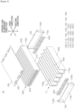
- FIG. 2 is an exploded perspective view schematically illustrating a battery module according to an embodiment of the present invention.
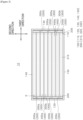
- FIG. 3 is a plan view of the battery module of FIG. 2 with the cover removed.
- FIG. 4 is a diagram illustrating a state in which the battery cell in FIG. 3 has been removed.
- FIG. 5 is a top view of the battery module of FIG. 2 .
- FIG. 6 is a side cross-sectional view of component C of FIG. 2 .
- FIG. 7 is a flowchart of a manufacturing method of a battery module according to an embodiment of the present invention.
- the battery module 10 may include a housing 100, a plurality of busbars 200, a plurality of battery cells 300, and one or more barriers 400. Each element will be described hereinafter.
- the housing 100 may be provided with a hollow space S therein.
- the housing 100 may include a base 110 and a first sidewall 120 or a second sidewall 130. Additionally, the housing 100 may include a third sidewall 140 and a fourth sidewall 150. In addition, housing 100 may include a cover 160.
- the base 110 may extend in the first direction (e.g., left and right directions) and the second direction (e.g., front and rear directions).
- the base 110 may have a plate shape.
- the first sidewall 120 may extend from one end portion (left side end portion) in the first direction of the base 110 in upward direction.
- the first sidewall 120 may have a plate shape.
- the second sidewall 130 may extend from other end portion (right side end portion) in the first direction of the base 110 in the upward direction.
- the second sidewall 130 may have a plate shape.
- the third sidewall 140 may extend from one end portion in the second direction of the base 110 in the upward direction.
- the third sidewall 140 may have a plate shape.
- the fourth sidewall 150 may extend from the other end portion in the second direction of the base 110 in the upward direction.
- the fourth sidewall 150 may have a plate shape.
- the cover 160 may cover the upper portion of the hollow space S of the housing 100.
- One or more exhaust holes 162 may be provided at the cover 160.
- the one or more exhaust holes 162 may penetrate the cover 160.
- the one or more exhaust holes 162 may exhaust flame, heat or gas generated from the battery cell 300 installed in the hollow space S to an outside of the housing 100.
- heat may be prevented from being accumulated or concentrated inside the housing 100, the amount of transferred heat may be reduced, and heat transfer may be delayed. Therefore, the possibility of ignition or explosion of the battery module 10 may be reduced.
- a plurality of busbars 200 may be provided.
- the plurality of busbars 200 may be installed at one end portion and the other end portion in the first direction of the hollow space S of the housing 100.
- the busbar may be provided with a hole through which the electrodes 320 and 330 of the battery cell 300 pass.
- the plurality of busbars 200 may include one side busbar 200a and the other side busbar 200b ( FIG. 3 ). The description thereof will be given later.
- a plurality of battery cells 300 may be provided.
- the battery cell 300 may include a body 310 and a pair of electrodes 320 and 330.
- the body 310 may be disposed at a center portion in the first direction of the hollow space S.
- the body 310 may be a portion wrapped with a pouch of a laminate having an electrode and a separator stacked therein.
- the pair of electrodes 320 and 330 may be in contact with the plurality of busbars 200.
- the electrodes 320 and 330 may penetrate the hole provided in the busbar 200 and then be bent and fused or welded to the busbar 200.
- the plurality of battery cells 300 may be placed in the hollow space S of the housing 100.
- the plurality of battery cells 300 may be arranged side by side in the second direction that intersects the first direction and upward and downward directions.
- the plurality of battery cells 300 may be connected in series or parallel.
- eight banks of two battery cells 300 connected in parallel may be connected in series. However, it is not limited to this configuration.
- the electrodes 320 and 330 of the plurality of battery cells 300 may be installed in a manner that the same polarities are aligned in the second direction. Between a pair of banks connected in series, the electrodes 320 and 330 of the battery cell 300 may be installed in a manner that opposite polarities are aligned in the second direction.
- the plurality of battery cells 300 may include one side battery cell 300a and the other side battery cell 300b ( FIG. 3 ).
- the one side battery cell 300a and the other side battery cell 300b may be battery cells 300 that belong to a pair of banks adjacent to each other, are disposed adjacent to each other, and are connected in series. The description thereof will be given later.
- the lower end portion of the barrier 400 may be coupled to a portion of the upper surface of the base 110 of the housing 100 ( FIGS. 2 and 6 ).
- the barrier 400 may be formed integrally with at least a portion of the housing 100 or may be formed separately. The description thereof will be given later.
- the barrier 400 may be made of a material with excellent thermal insulation properties including aerogel, mica, superwool and glass fiber. However, it is not limited to these materials.
- the barrier 400 may be a heat absorbing sheet made of a material that rapidly absorbs heat through a dehydration reaction.
- the barrier 400 is installed between the bodies 310 of a pair of battery cells 300 arranged adjacent to each other in the second direction to partition, in the second direction, the center portion in the first direction of the hollow space S of the housing 100.
- heat transfer between the center portion in the first direction inside the housing 100 and the battery cell 300 at one end portion or the other end portion of the housing 100 may be delayed or prevented.
- one end portion or the other end portion in the first direction of the inside the housing 100 in which as heat transfer between the battery cells 300 is inevitable due to the busbar 200 connecting the plurality of battery cells 300, is partitioned by the barrier 400.
- the heat transfer between battery cells 300 may be effectively delayed or prevented.
- the barrier 400 since it is partitioned by the barrier 400, rapid heat transfer between the non-adjacent battery cells 300 in the second direction having a large electric potential difference therebetween occurring at the one end portion or the other end portion in the first direction of the inside the housing 100 may be prevented. Therefore, the possibility of ignition or explosion of the battery module 10 may be reduced. Detail description thereof is as follows.
- a bank is constituted by count of n battery cells 300 (n is a natural number) arranged side by side in the second direction and connected in parallel (two in the drawing), and a plurality of the banks (eight in the drawing) are sequentially connected in series
- a pair of non-adjacent battery cells 300 in the second direction have a potential difference that increases as the number of battery cells 300 or banks connected and arranged between the pair of battery cells 300 increases.
- the possibility of problems such as short circuits occurring in the battery cell 300 increases such that the thermal runaway phenomenon may rapidly spread to the battery cell 300 with a large potential difference resulting in significant increase in the probability of the ignition or explosion of the battery module 10. Therefore, when rapid heat transfer between battery cells 300 is prevented by partitioning one end portion or the other end portion in the first direction of the inside the housing 100 with the barrier 400, the possibility of ignition and explosion may be reduced.
- one or more barriers 400 may extend to one side or the other side in the first direction, respectively, and may contact the first sidewall 120 or the second sidewall 130 of the housing 100. Accordingly, one or more barriers 400 may partition, in the second direction, one end portion or the other end portion in the first direction of the hollow space S of the housing 100.
- the housing 100 and barrier 400 may be easily constructed with a simple configuration and at low cost.
- the one or more barrier 400 may include the first barrier 400a or the second barrier 400b.
- the first barrier 400a may extend toward the one side of the first direction to be in contact with the first sidewall 120. Accordingly, the first barrier 400a may partition, in the second direction, one end portion in the first direction of the hollow space S of the housing 100.
- the first barrier 400a may be at least partially spaced apart from the second sidewall 130.
- the second barrier 400b extends to the other side in the first direction and can contact the second sidewall 130 of the housing 100. Accordingly, the second barrier 400b may partition, in the second direction, the other end portion in the first direction of the hollow space S of the housing 100.
- the second barrier 400b may be at least partially spaced apart from the first sidewall 120.
- the above-described one side busbar 200a and the other side busbar 200b may be installed: at one side and other side of the second direction of one side in the first direction of the first barrier 400a, respectively, adjacent to the first barrier 400a with the first barrier 400a therebetween while physically separated from each other; or at the one side and the other side of the second direction of other side in the first direction of the second barrier 400b, respectively, adjacent to the second barrier 400b with the second barrier 400b therebetween while physically separated from each other.
- one side battery cell 300a and the other side battery cell 300b may be disposed: at one side and other side in the second direction of the first barrier 400a, respectively, adjacent to the first barrier 400a; or at one side and other side in the second direction of the second barrier 400b, respectively, adjacent to the second barrier 400b.
- the pair of electrodes 320 and 330 of the one side battery cell 300a may be in contact with: the one side busbar 200a; and one of the plurality of busbars 200 installed between the first barrier 400a and the second sidewall 130 or installed between the second barrier 400b and the first sidewall 120.
- the pair of electrodes 320 and 330 of the other side battery cell 300b may be in contact with: the other side busbar 200b; and one of the plurality of busbars 200 installed between the first barrier 400a and the second sidewall 130 or installed between the second barrier 400b and the first sidewall 120.
- the space between the first barrier 400a and the second sidewall 130 may be defined by a space where the first barrier 400a is at least partially spaced apart from the second sidewall 130.
- the space between the second barrier 400b and the first sidewall 120 may be defined by a space where the second barrier 400b is at least partially spaced apart from the first sidewall 120.
- one side battery cell 300a and the other side battery cell 300b may be connected to each other in series.
- the one side busbar 200a and the other side busbar 200b are physically separated from each other with the first barrier 400a or second barrier 400b therebetween, the one end portion or the other end portion in the first direction of the inside the housing 100 is clearly partitioned by the first barrier 400a or second barrier 400b. Therefore, heat transfer between battery cells 300 may be effectively delayed or prevented.
- the electrode 330 or 320 at the other side in the first direction of the one side battery cell 300a and the other side battery cell 300b may be electrically connected to each other (in series) even when the electrode 330 or 320 at the one side in the first direction of the one side battery cell 300a and the other side battery cell 300b are not connected to each other due to the physical separation between the one side busbar 200a and the other side busbar 200b. That is, the one end portion or the other end portion in the first direction of the inside the housing 100 is clearly partitioned by the first barrier 400a or the second barrier 400b while electrically connecting the one side battery cell 300a and the other side battery cell 300b.
- the one side busbar 200a and the other side busbar 200b may not be physically separated.
- the one side busbar 200a and the other side busbar 200b may be connected to each other while penetrating the first barrier 400a or the second barrier 400b.
- a plurality of barriers 400 may be provided.
- the plurality of barriers 400 may include one or more first barriers 400a and one or more second barriers 400b.
- the one or more first barriers 400a may extend to the one end portion in the first direction of the housing 100 such that one end portion in the first direction of the hollow space S of housing 100 is partitioned in the second direction.
- the one or more second barriers 400b may extend to the other end portion in the first direction of the housing 100 such that the other end portion in the first direction of the hollow space S of housing 100 is partitioned in the second direction.
- the first barrier 400a and the second barrier 400b may be alternately arranged along the second direction.
- the busbars 200 installed at one side and the other side in first direction of one side in the second direction of the first barrier 400a, respectively, may be physically separated from each other with the first barrier 400a therebetween.
- the one side busbars 200a and the other side busbar 200b installed adjacent to the first barrier 400a at one side and the other side in first direction of the one side in the second direction of the first barrier 400a, respectively, may be physically separated from each other with the first barrier 400a therebetween.
- the busbars 200 installed at one side and the other side in first direction of the other side in the second direction of the second barrier 400b, respectively, may be physically separated from each other with the second barrier 400b therebetween.
- the one side busbars 200a and the other side busbar 200b installed adjacent to the second barrier 400b at one side and the other side in first direction of the other side in the second direction of the second barrier 400b, respectively, may be physically separated from each other with the second barrier 400b therebetween.
- busbars 200 are physically separated from each other with the first barrier 400a and the second barrier 400b there between, the one end portion and the other end portion in the first direction of the inside the housing 100 are clearly partitioned by the first barrier 400a and second barrier 400b. Therefore, heat transfer between battery cells 300 may be effectively delayed or prevented.
- the electrodes at the other side may be electrically connected to each other (in series) through the busbar 200c installed at the other side in the first direction of the first barrier 400a or through the busbar 200c installed at one side in the first direction of the second barrier 400b even when one electrode at the one side in the first direction of the battery cells 300 disposed at one side and the other side in the second direction of the first barrier 400a and the second barrier 400b are not connected to each other due to the physical separation between the busbars 200 with the first barrier 400a and the second barrier 400b therebetween. That is, the one end portion and the other end portion in the first direction of the inside the housing 100 is clearly partitioned by the first barrier 400a and the second barrier 400b while electrically connecting the battery cells 300.
- the busbars 200 may not be physically separated from each other with the first barrier 400a or the second barrier 400b therebetween.
- the busbars 200 may be connected to each other while penetrating the first barrier 400a or the second barrier 400b.
- the one or more first barriers 400a may not partition, in the second direction, the other end portion in the first direction of the hollow space S of the housing 100.
- the one or more second barriers 400b may not partition, in the second direction, the one end portion in the first direction of the hollow space S of thee housing 100.
- the flame, heat or gas may reach other battery cells 300 by repeatedly traveling back and forth between two end portions of the housing 100 in the first direction as indicated by dotted arrow A of FIG. 4 .
- the flame, heat or gas generated from the battery cell 300 may transfer/propagate/spread through the one end portion or the other end portion in thee first direction of the housing 100 that is not partitioned by the first barrier 400a and the second barrier 400b in the second direction. Therefore, the possibility of ignition or explosion of the battery module 10 may be reduced.
- the battery module 10 may be lightweight.
- a hollow space may be provided in which the busbar 200 may be installed at the other side in the first direction of the first barrier 400a and at one side in the first direction of the second barrier 400b. Therefore, in order to perform insert installation or penetration installation of the busbar 200 at the other side in the first direction of the first barrier 400a and at one side in the first direction of the second barrier 400b, it is nor necessary to process the first barrier 400a and the second barrier 400b. Thus, the manufacturing cost of the battery module 10 may be reduced and the manufacturing time may be shortened.
- At least a portion of the plurality of busbars 200 may be installed at the other side in the first direction of the first barrier 400a or at one side in the first direction of the second barrier 400b.
- the busbar 200 may be easily installed and replaced, the manufacturing and maintenance costs of the battery module 10 may be reduced.
- the one or more exhaust holes 162 may be provided at an upper portion of other side of the first direction of the one or more first barriers 400a or an upper portion of one side of the first direction of the one or more second barriers 400b ( FIG. 5 ).
- the other side in the first direction of the first barrier 400a and one side in the first direction of the second barrier 400b are where transfer (propagation) direction of flame, heat or gas changes rapidly as indicated by the dotted arrow A in FIG. 4 .
- exhaust holes 162 are provided in areas where the direction of transfer (propagation) of flame, heat or gas rapidly changes, flame, heat or gas is prevented from being accumulated or concentrated, and flame, and heat or gas may be effectively discharged to the outside of the housing 100 even when the number or the size of exhaust holes 162 are small. Therefore, the possibility of ignition or explosion of the battery module 10 may be reduced.
- the first barriers 400a may extend in the first direction to the other end portion in the first direction of the housing 100 to partition, in the second direction, the other end portion in the first direction of the hollow space S.
- the busbar 200 may be installed to penetrate the other side in the first direction of the first barrier 400a.
- the second barrier 400b may extend in the first direction to the one end portion in the first direction of the housing 100 to partition, in the second direction, the one end portion in the first direction of the hollow space S.
- the busbar 200 may be installed to penetrate the one side in the first direction of the first barrier 400a.
- the manufacturing method of a battery module S500 may include a housing manufacturing step S510 and an assembly step S520.
- the housing 100 may be manufactured.
- the housing 100 may be extruded rather than formed using a press processing method.
- At least a portion of the barriers 400 among the one or more barriers 400 may be extruded integrally with at least a portion of the housing 100.
- the manufacturing cost of the battery module 10 may be reduced and the manufacturing time may be shortened.
- At least portion 110a of the base 110, a portion 140a of the third sidewall 140 and a portion 150b of the fourth sidewall 150, and at least a portion of the one or more barriers 400 may be extruded integrally (component C of FIG. 2 and FIG. 6 ).
- the manufacturing cost of the battery module 10 may be reduced and the manufacturing time may be shortened.
- both ends may be cut in the first direction such that the plurality of barriers 400 are alternately protrudes toward the both sides of the first direction, as component C shown in FIG. 2 .
- the barrier 400 may not be manufactured integrally with at least a portion of the housing 100.
- the busbar 200 may be installed inside the housing 100 and the battery cell 300 may be placed.
- the electrodes 320 and 330 of the battery cell 300 and the busbar 200 may be coupled in advance.
- the barrier 400 manufactured separately from the housing 100 may be attached to the housing 100 before placing the battery cell 300 and installing the busbar 200 in the assembly step S520.
- battery module 100 housing 110: base 120: first sidewall 130: second sidewall 140: third sidewall 150: fourth sidewall 160: cover 162: exhaust hole 200: busbar 300: battery cell 310: body 320, 330: electrode 400: barrier
Landscapes
- Chemical & Material Sciences (AREA)
- Chemical Kinetics & Catalysis (AREA)
- Electrochemistry (AREA)
- General Chemical & Material Sciences (AREA)
- Engineering & Computer Science (AREA)
- Manufacturing & Machinery (AREA)
- Battery Mounting, Suspending (AREA)
- Connection Of Batteries Or Terminals (AREA)
- Gas Exhaust Devices For Batteries (AREA)
Abstract
Description
- This application claims the benefit of priority based on
Korean Patent Application No. 10-2022-0072093, dated June 14, 2022 - The present invention relates to a battery module and a manufacturing method of a battery module, and more particularly, to a battery module and a manufacturing method of a battery module in which heat transfer between battery cells is delayed or prevented and manufacturing costs are reduced.
- A secondary battery refers to a battery that may be charged and discharged, unlike primary batteries that cannot be recharged. These secondary batteries are used in small, high-tech electronic devices such as mobile phones, PDAs and laptop computers as well as in energy storage systems (ESS), electric vehicles (EV) or hybrid electric vehicles (HEV) as a power source.
- A battery module refers to a device in which a plurality of secondary batteries (referred to as "battery cells" hereinafter) is connected in series or parallel. When a problem such as a short circuit occurs in some of the battery cells in the battery module and the temperature of the battery cell exceeds the critical temperature, a thermal runaway phenomenon may occur.
- Heat and flame generated by the thermal runaway phenomenon of some battery cells in the battery module elevate the temperature of other battery cells, which can cause the thermal runaway phenomenon to spread to other battery cells. When the thermal runaway phenomenon rapidly spreads to other battery cells, the possibility of ignition or explosion of the battery module increases. Therefore, it is necessary to delay heat transfer between battery cells. In this regard, description will be given with reference to
FIG. 1 . -
FIG. 1 is a plan view illustrating a conventional battery module. - Referring to
FIG. 1 , aconventional battery module 1 may include ahousing 2, abusbar 3 and abattery cell 4. A plurality ofbattery cells 4 may be electrically connected to thebusbar 3. - For example, when a thermal runaway phenomenon occurs in the
battery cell 4 shown at the upper end of the drawing (one end of the second direction), heat, flame, etc. may be transferred/propagated, thereby propagating the thermal runaway phenomenon to thebattery cell 4 adjacent to thebattery cell 4 shown at the upper end of the drawing. Moreover, for example, heat, flame, etc. may be transferred/propagated through thebusbar 3 or the space where thebusbar 3 is installed, as shown by the dashed-dotted arrow A such that the thermal runaway phenomenon is propagated even to the battery cell that is not adjacent to thebattery cell 4 shown at the upper end of the drawing. - Here, when the plurality of
battery cells 4 inFIG. 1 are connected in series, the thermal runaway phenomenon can spread more rapidly tonon-adjacent battery cells 300, and the possibility of the battery module igniting or exploding increases. In case the plurality ofbattery cells 4 connected in series, a pair ofbattery cells 4 that are not adjacent to each other have a larger potential difference than a pair ofadjacent battery cells 4 such that the possibility of the problem of short circuit in thebattery cell 4 increases due to the thermal runaway phenomenon spreading more rapidly tonon-adjacent battery cells 300 having a large potential difference. - Therefore, in order to reduce the possibility of ignition or explosion of the battery module, not only the heat transfer between
adjacent battery cells 4 but also the heat transfer betweennon-adjacent battery cells 4 must be delayed. Prior art related to delaying heat transfer between battery cells is as follows. -
Korean Patent Application Publication No. 10-2022-0014117 - However, the prior art does not provide a method to delay heat transfer between
non-adjacent battery cells 4. - (Patent Document 0001)
Korean Patent Application Publication No. 10-2022-0014117 - In order to solve the above-described problems, it is an object of the present invention to provide a battery module in which heat transfer between battery cells is delayed or prevented.
- It is an object of the present invention to provide a battery module capable of reducing the possibility of ignition or explosion of the
battery module 10. - It is an object of the present invention to provide a battery module that delays or prevents heat transfer between battery cells while connecting the battery cells to one another electrically.
- It is an object of the present invention to provide a battery module that is lightweight, reduces manufacturing and maintenance costs, and shortens manufacturing time.
- Objects of the present invention are not limited to the above-described objects, and other objects and advantages of the present invention will be understood by the following description and will be more definitely understood through the embodiments of the present invention. It is also to be easily understood that the objectives and advantages of the present invention may be realized and attained by means and a combination thereof described in the appended claims.
- In order to solve the above-described problems, the present invention provides a battery module including a housing 100, a plurality of
busbars 200, a plurality ofbattery cells 300 and one ormore barriers 400. - The housing 100 may be provided with a hollow space S therein.
- The plurality of
busbars 200 may be installed at one end portion and the other end portion in the first direction of the hollow space S. - The plurality of
battery cells 300 are arranged in the hollow space S side by side in a second direction that intersects the first direction and upward and downward directions. - Each of the plurality of
battery cells 300 may include abody 310 and a pair ofelectrodes - The
body 310 may be disposed at a center portion in the first direction of the hollow space S. - The pair of
electrodes body 310 toward one side and the other side of the first direction. - The pair of
electrodes busbar 200. - The one or
more barriers 400 may extend in the first direction and the upward and downward directions. - The one or
more barriers 400 may be installed between thebodies 310 of a pair of thebattery cells 300 arranged adjacent to each other in the second direction to partition, in the second direction, the center portion in the first direction of the hollow space S to. - The one or
more barriers 400 may extend in the first direction to one end portion or other end portion in the first direction of the housing 100 to partition, in the second direction, the one end portion or the other end portion in the first direction of the hollow space S. - A pair of the plurality of
busbars 200 which are installed at one side and other side in the second direction of each of the one ormore barriers 400 with the each of the one ormore barriers 400 therebetween may be physically separated in the second direction by the one ormore barriers 400. - In one embodiment, the housing 100 may include a
base 110 and afirst sidewall 120 or asecond sidewall 130. - The
base 110 may be extended in the first direction and the second direction. - The
first sidewall 120 may extend from one end portion in the first direction of thebase 110 in the upward direction. - The
second sidewall 130 may extend from the other end portion in the first direction of thebase 110 in the upward direction. - Each of the one or
more barriers 400 may extend to the one side or the other side of the first direction to be in contact with thefirst sidewall 120 or thesecond sidewall 130 and accordingly partitions, in the second direction, the one end portion or the other end portion in the first direction of the hollow space S. - In one embodiment, the one or
more barriers 400 may include afirst barrier 400a or asecond barrier 400b. - The
first barrier 400a may extend to one side of the first direction and is in contact with thefirst sidewall 120, thereby partitioning, in the second direction, the one end portion in the first direction of the hollow space S. - The
first barrier 400a may be at least partially separated from thesecond sidewall 130. - The
second barrier 400b may extend to the other side of the first direction and is in contact with thesecond sidewall 130, thereby partitioning, in the second direction, the other end portion in the first direction of the hollow space S. - The
second barrier 400b may be at least partially separated from thefirst sidewall 120. - The plurality of
busbars 200 may include oneside busbar 200a and theother side busbar 200b. - The one
side busbar 200a and theother side busbar 200b may be installed: at one side and other side of the second direction of one side in the first direction of thefirst barrier 400a, respectively, adjacent to thefirst barrier 400a with thefirst barrier 400a therebetween while physically separated from each other; or at the one side and the other side of the second direction of other side in the first direction of thesecond barrier 400b, respectively, adjacent to thesecond barrier 400b with thesecond barrier 400b therebetween while physically separated from each other. - The plurality of
battery cells 300 may include oneside battery cell 300a and the otherside battery cell 300b. - The one
side battery cell 300a and the otherside battery cell 300b may be disposed: at one side and other side in the second direction of thefirst barrier 400a, respectively, adjacent to thefirst barrier 400a; or at one side and other side in the second direction of thesecond barrier 400b, respectively, adjacent to thesecond barrier 400b. - The pair of
electrodes side battery cell 300a may be in contact with: the oneside busbar 200a; and one of the plurality ofbusbars 200 installed between thefirst barrier 400a and thesecond sidewall 130 or installed between thesecond barrier 400b and thefirst sidewall 120. - The pair of
electrodes side battery cell 300b may be in contact with: theother side busbar 200b; and one of the plurality ofbusbars 200 installed between thefirst barrier 400a and thesecond sidewall 130 or installed between thesecond barrier 400b and thefirst sidewall 120. - Accordingly, the one
side battery cell 300a and the otherside battery cell 300b may be connected in series. - In one embodiment, a plurality of the
barriers 400 may be provided. - The plurality of
barriers 400 may include one or morefirst barriers 400a and one or moresecond barriers 400b. - The one or more
first barriers 400a may extend to the one end portion in the first direction of the housing 100 to partition, in the second direction, the one end portion in the first direction of the hollow space S. - The one or more
second barriers 400b may extend to the other end portion in the first direction of the housing 100 to partition the other end portion in the first direction of the hollow space S in the second direction. - The one or more
first barriers 400a and the one or moresecond barriers 400b may be alternately arranged along the second direction. - The
busbar 200 installed at each of one side and other side of the second direction of one side in the first direction of the one or morefirst barriers 400a may be physically separated from each other with the one or morefirst barriers 400a therebetween. - The
busbar 200 installed at each of one side and other side of the second direction of other side in the first direction of the one or moresecond barriers 400b may be physically separated from each other with the one or moresecond barriers 400b therebetween. - In one embodiment, a plurality of the
barriers 400 may be provided. - The plurality of
barriers 400 may include one or morefirst barriers 400a and one or moresecond barriers 400b. - The one or more
first barriers 400a may extend to the one end portion in the first direction of the housing 100 to partition, in the second direction, the one end portion in the first direction of the hollow space S. - The one or more
second barriers 400b may extend to the other end portion in the first direction of the housing 100 to partition the other end portion in the first direction of the hollow space S in the second direction. - The one or more
first barriers 400a may not partition, in the second direction, the other end portion in the first direction of the hollow space S. - The one or more
second barriers 400b may not partition, in the second direction, the one end portion in the first direction of the hollow space S. - The one or more
first barriers 400a and the one or moresecond barriers 400b are alternately arranged along the second direction. - In one embodiment, at least a portion of the plurality of
busbars 200 may be installed at other side in the first direction of the one or morefirst barriers 400a or at one side in the first direction of the one or moresecond barriers 400b. - In one embodiment, the housing 100 may include a
cover 160 covering an upper portion of the hollow space S. - The
cover 160 may be provided with one or more exhaust holes 162. - The one or
more exhaust holes 162 may penetrate thecover 160. - The one or
more exhaust holes 162 may exhaust flame, heat or gas generated from thebattery cell 300 installed in the hollow space S to an outside of the housing 100. - In one embodiment, a plurality of the
barriers 400 may be provided. - The plurality of
barriers 400 may include one or morefirst barriers 400a and one or moresecond barriers 400b. - The one or more
first barriers 400a may extend to the one end portion in the first direction of the housing 100 to partition, in the second direction, the one end portion in the first direction of the hollow space S. - The one or more
second barriers 400b may extend to the other end portion in the first direction of the housing 100 to partition the other end portion in the first direction of the hollow space S in the second direction. - The one or more
first barriers 400a may not partition, in the second direction, the other end portion in the first direction of the hollow space S. - The one or more
second barriers 400b may not partition, in the second direction, the one end portion in the first direction of the hollow space S. - The one or more
first barriers 400a and the one or moresecond barriers 400b are alternately arranged along the second direction. - Te one or
more exhaust holes 162 are provided at an upper portion of other side of the first direction of the one or morefirst barriers 400a or an upper portion of one side of the first direction of the one or moresecond barriers 400b. - In addition, in order to solve the above-described problem, the present invention provides a manufacturing method of a battery module S500 including a housing manufacturing step S510 for manufacturing the housing 100.
- In the housing manufacturing step S510, at least a portion of the housing 100 and at least a portion of the one or
more barriers 400 may be integrally extruded. - In one embodiment, the housing 100 may include a
base 110, athird sidewall 140, and afourth sidewall 150. - The base 110 may be extended in the first direction and the second direction.
- The
third sidewall 140 may extend from one end portion in the second direction of the base 110 in the upward direction. - The
fourth sidewall 150 may extend from the other end portion in the second direction of the base 110 in the upward direction. - The at least a portion of the one or
more barriers 400 may be coupled to at least a portion of the upper surface of thebase 110. - In the housing manufacturing step S510, at least a portion of the
base 110, at least a portion of thethird sidewall 140 and at least a portion of thefourth sidewall 150, and the at least a portion of the one ormore barriers 400 may be integrally extruded. - According to embodiments of the present invention, the battery module 10 may include: a housing 100 having a hollow space S therein; a plurality of busbars 200 installed at one end portion and other end portion in a first direction of the hollow space S; a plurality of battery cells 300 disposed in the hollow space S along a second direction intersecting the first direction and upward and downward directions, wherein each of the plurality of battery cells 300 comprises: a body 310 disposed at a center portion in the first direction of the hollow space S; and a pair of electrodes 320 and 330 in contact with the plurality of busbars 200 and protruding from the body 310 toward one side and other side of the first direction; and one or more barriers 400 extending in the first direction and the upward and downward directions, wherein each of one or more barriers 400 is: disposed between the body 310 of a pair of battery cells 300 adjacent to each other in the second direction to partition, in the second direction, the center portion in the first direction of the hollow space S; and extending to one end portion or other end portion in the first direction of the housing 100 to partition, in the second direction, the one end portion or the other end portion in the first direction of the hollow space S. As a result, heat transfer between the center portion in the first direction inside the housing 100 and the battery cell 300 at one end portion or the other end portion of the housing 100 may be delayed or prevented.
- Accordingly, even when a problem such as a short circuit occurs in some
battery cells 300 resulting in a thermal runaway phenomenon, rapid spread of the thermal runaway phenomenon toother battery cells 300 is prevented, thereby reducing the possibility of ignition or explosion of thebattery module 10. - In particular, one end portion or the other end portion in the first direction of the inside the housing 100, in which heat transfer between the
battery cells 300 is inevitable due to thebusbar 200 connecting the plurality ofbattery cells 300, is partitioned by thebarrier 400. Thus, the heat transfer betweenbattery cells 300 may be effectively delayed or prevented. - In addition, since it is partitioned by the
barrier 400, rapid heat transfer between thenon-adjacent battery cells 300 in the second direction having a large electric potential difference therebetween occurring at the one end portion or the other end portion in the first direction of the inside the housing 100 may be prevented. Therefore, the possibility of ignition or explosion of thebattery module 10 may be reduced. - According to embodiments of the present invention, the housing 100 may include: a base 110 extending in the first direction and the second direction; and a
first sidewall 120 extending in the upward direction from one end portion in the first direction of the base 110 or asecond sidewall 130 extending in the upward direction from other end portion in the first direction of thebase 110. Each of the one ormore barriers 400 may extend to the one side or the other side of the first direction to be in contact with thefirst sidewall 120 or thesecond sidewall 130 and accordingly partitions, in the second direction, the one end portion or the other end portion in the first direction of the hollow space S. - Accordingly, the housing 100 and the
barrier 400 may be easily constructed with a simple configuration and at low cost. - According to embodiments of the present invention, the one or
more barriers 400 may include: afirst barrier 400a extending toward the one side of the first direction to be in contact with thefirst sidewall 120, partitioning, in the second direction, one end portion in the first direction of the hollow space S, and at least partially spaced apart from thesecond sidewall 130; or asecond barrier 400b extending toward the other side of the first direction to be in contact with thesecond sidewall 130, partitioning, in the second direction, the other end portion in the first direction of the hollow space S, and at least partially spaced apart from thefirst sidewall 120. The plurality ofbusbars 200 may include oneside busbar 200a andother side busbar 200b. The oneside busbar 200a and theother side busbar 200b may be installed: at one side and other side of the second direction of one side in the first direction of thefirst barrier 400a, respectively, adjacent to thefirst barrier 400a with thefirst barrier 400a therebetween while physically separated from each other; or at the one side and the other side of the second direction of other side in the first direction of thesecond barrier 400b, respectively, adjacent to thesecond barrier 400b with thesecond barrier 400b therebetween while physically separated from each other. The plurality ofbattery cells 300 may include oneside battery cell 300a and otherside battery cell 300b. The oneside battery cell 300a and the otherside battery cell 300b are disposed: at one side and other side in the second direction of thefirst barrier 400a, respectively, adjacent to thefirst barrier 400a; or at one side and other side in the second direction of thesecond barrier 400b, respectively, adjacent to thesecond barrier 400b. A pair ofelectrodes side battery cell 300a may be in contact with: the oneside busbar 200a; and one of the plurality ofbusbars 200 installed between thefirst barrier 400a and thesecond sidewall 130 or installed between thesecond barrier 400b and thefirst sidewall 120. A pair ofelectrodes side battery cell 300b are in contact with: theother side busbar 200b; and one of the plurality ofbusbars 200 installed between thefirst barrier 400a and thesecond sidewall 130 or installed between thesecond barrier 400b and thefirst sidewall 120. Thus, the oneside battery cell 300a and the otherside battery cell 300b may be connected in series. - Accordingly, since the one
side busbar 200a and theother side busbar 200b are physically separated from each other with thefirst barrier 400a orsecond barrier 400b therebetween, the one end portion or the other end portion in the first direction of the inside the housing 100 is clearly partitioned by thefirst barrier 400a orsecond barrier 400b. Therefore, heat transfer betweenbattery cells 300 may be effectively delayed or prevented. - In addition, the
electrode side battery cell 300a and the otherside battery cell 300b may be electrically connected to each other (in series) even when theelectrode side battery cell 300a and the otherside battery cell 300b are not connected to each other due to the physical separation between the oneside busbar 200a and theother side busbar 200b. That is, the one end portion or the other end portion in the first direction of the inside the housing 100 is clearly partitioned by thefirst barrier 400a or thesecond barrier 400b while electrically connecting the oneside battery cell 300a and the otherside battery cell 300b. - According to embodiments of the present invention, a plurality of
barriers 400 may be provided. The plurality ofbarriers 400 may include: one or morefirst barriers 400a extending to the one end portion in the first direction of the housing 100 to partition, in the second direction, the one end portion in the first direction of the hollow space S; and one or moresecond barriers 400b extending to the other end portion in the first direction of the housing 100 to partition the other end portion in the first direction of the hollow space S in the second direction. The one or morefirst barriers 400a and the one or moresecond barriers 400b are alternately arranged along the second direction. Thebusbar 200 installed at each of one side and other side of the second direction of one side in the first direction of the one or morefirst barriers 400a may be physically separated from each other with the one or morefirst barriers 400a therebetween. Thebusbar 200 installed at each of one side and other side of the second direction of other side in the first direction of the one or moresecond barriers 400b is physically separated from each other with the one or moresecond barriers 400b therebetween. - Accordingly, since the
busbars 200 are physically separated from each other with thefirst barrier 400a and thesecond barrier 400b therebetween, the one end portion and the other end portion in the first direction of the inside the housing 100 are clearly partitioned by thefirst barrier 400a andsecond barrier 400b. Therefore, heat transfer betweenbattery cells 300 may be effectively delayed or prevented. - In addition, the electrodes at the other side may be electrically connected to each other (in series) through the
busbar 200c installed at the other side in the first direction of thefirst barrier 400a or through thebusbar 200c installed at one side in the first direction of thesecond barrier 400b even when one electrode at the one side in the first direction of thebattery cells 300 disposed at one side and the other side in the second direction of thefirst barrier 400a and thesecond barrier 400b are not connected to each other due to the physical separation between thebusbars 200 with thefirst barrier 400a and thesecond barrier 400b therebetween. That is, the one end portion and the other end portion in the first direction of the inside the housing 100 are clearly partitioned by thefirst barrier 400a and thesecond barrier 400b while electrically connecting thebattery cells 300. - According to embodiments of the present invention, a plurality of
barriers 400 may be provided. The plurality ofbarriers 400 may include: one or morefirst barriers 400a extending to the one end portion in the first direction of the housing 100 to partition, in the second direction, the one end portion in the first direction of the hollow space S; and one or moresecond barriers 400b extending to the other end portion in the first direction of the housing 100 to partition the other end portion in the first direction of the hollow space S in the second direction. The one or morefirst barriers 400a may not partition, in the second direction, the other end portion in the first direction of the hollow space S. The one or moresecond barriers 400b do not partition, in the second direction, the one end portion in the first direction of the hollow space S. The one or morefirst barriers 400a and the one or moresecond barriers 400b are alternately arranged along the second direction. - Accordingly, the flame, heat or gas generated from the
battery cell 300 may transfer/propagate/spread through the one end portion or the other end portion in thee first direction of the housing 100 that is not partitioned by thefirst barrier 400a and thesecond barrier 400b in the second direction. Therefore, the possibility of ignition or explosion of thebattery module 10 may be reduced. - In addition, since flame, heat or gas generated from the
battery cell 300 is able to reach theother battery cell 300 only by repeatedly traveling back and forth between two end portions of the housing 100 in the first direction, the transfer of flame, heat or gas betweenbattery cells 300 may be delayed. Therefore, the possibility of ignition or explosion of thebattery module 10 may be reduced. - In addition, since the flame or heat generated from the
battery cell 300 sequentially propagates in the second direction to theadjacent battery cells 300 having a small potential difference, the possibility of ignition or explosion of thebattery module 10 is reduced, and even when ignition or explosion occurs, damage may be reduced. - Additionally, since the lengths in the first direction of the
first barrier 400a and thesecond barrier 400b are reduced, thebattery module 10 may be lightweight. - Additionally, a hollow space may be provided in which the
busbar 200 may be installed at the other side in the first direction of thefirst barrier 400a and at one side in the first direction of thesecond barrier 400b. Therefore, in order to perform insert installation or penetration installation of thebusbar 200 at the other side in the first direction of thefirst barrier 400a and at one side in the first direction of thesecond barrier 400b, it is nor necessary to process thefirst barrier 400a and thesecond barrier 400b. Thus, the manufacturing cost of thebattery module 10 may be reduced and the manufacturing time may be shortened. - According to embodiments of the present invention, at least a portion of the plurality of
busbars 200 may be installed at the other side in the first direction of thefirst barrier 400a or at one side in the first direction of thesecond barrier 400b. - Accordingly, since the
busbar 200 may be easily installed and replaced, the manufacturing and maintenance costs of thebattery module 10 may be reduced. - According to embodiments of the present invention, the housing 100 may include a
cover 160 that covers the upper portion of the hollow space S. Thecover 160 is provided with one ormore exhaust holes 162 penetrating thecover 160 for exhausting flame, heat or gas generated from thebattery cell 300 installed in the hollow space S to an outside of the housing 100. - Accordingly, heat may be prevented from being accumulated or concentrated inside the housing 100, the amount of transferred heat may be reduced, and heat transfer may be delayed. Therefore, the possibility of ignition or explosion of the
battery module 10 may be reduced. - According to embodiments of the present invention, a plurality of
barriers 400 may be provided. The plurality ofbarriers 400 may include: one or morefirst barriers 400a extending to the one end portion in the first direction of the housing 100 to partition, in the second direction, the one end portion in the first direction of the hollow space S; and one or moresecond barriers 400b extending to the other end portion in the first direction of the housing 100 to partition the other end portion in the first direction of the hollow space S in the second direction. The one or morefirst barriers 400a may not partition, in the second direction, the other end portion in the first direction of the hollow space S. The one or moresecond barriers 400b may not partition, in the second direction, the one end portion in the first direction of the hollow space S. The one or morefirst barriers 400a and the one or moresecond barriers 400b may be alternately arranged along the second direction. The one ormore exhaust holes 162 are provided at an upper portion of other side of the first direction of the one or morefirst barriers 400a or an upper portion of one side of the first direction of the one or moresecond barriers 400b. - Accordingly, since exhaust holes 162 are provided in areas where the direction of transfer (propagation) of flame, heat or gas rapidly changes, flame, heat or gas is prevented from being accumulated or concentrated, and flame, and heat or gas may be effectively discharged to the outside of the housing 100 even when the number or the size of
exhaust holes 162 are small. Therefore, the possibility of ignition or explosion of thebattery module 10 may be reduced. - According to embodiments of the present invention, the manufacturing method of a battery module may include a housing manufacturing step S510 of manufacturing a housing 100. In the housing manufacturing step S510, at least a portion of the housing 100 and at least a portion of the one or
more barriers 400 may be integrally extruded. - Accordingly, the manufacturing cost of the
battery module 10 may be reduced and the manufacturing time may be shortened. - According to embodiments of the present invention, the housing 100 may include: a base 110 extending in first and second directions; a
third sidewall 140 extending in an upward direction from one end portion in the second direction of thebase 110; and afourth sidewall 150 extending in the upward direction from other end portion of thebase 110. The at least a portion of the one ormore barriers 400 may be coupled to at least a portion of an upper surface of thebase 110. At least a portion of thebase 110, at least a portion of thethird sidewall 140 and at least a portion of thefourth sidewall 150, and the at least a portion of the one ormore barriers 400 may be integrally extruded in the housing manufacturing step S510. - Accordingly, the manufacturing cost of the
battery module 10 may be reduced and the manufacturing time may be shortened. - In addition to the above-described effects, specific effects of the present invention will be described together with the following detailed description for implementing the present invention.
-
-
FIG. 1 is a plan view illustrating a conventional battery module. -
FIG. 2 is an exploded perspective view schematically illustrating a battery module according to an embodiment of the present invention. -
FIG. 3 is a plan view of the battery module ofFIG. 2 with the cover removed. -
FIG. 4 is a diagram illustrating a state in which the battery cell inFIG. 3 has been removed. -
FIG. 5 is a top view of the battery module ofFIG. 2 . -
FIG. 6 is a side cross-sectional view of component C ofFIG. 2 . -
FIG. 7 is a flowchart of a manufacturing method of a battery module according to an embodiment of the present invention. - The above objects, features and advantages will be described later in detail with reference to the accompanying drawings, and accordingly, those skilled in the art to which the present invention belongs will be able to easily implement the technical idea of the present invention. In describing the present invention, when it is determined that the detailed description of the known technology related to the present invention may unnecessarily obscure the subject matter of the present invention, the detailed description will be omitted. Hereinafter, preferred embodiments according to the present invention will be described in detail with reference to the accompanying drawings. In the drawings, the same reference numerals are used to indicate the same or similar components.
- Although "first", "second", and the like may be used to describe various components, these components are not limited by these terms. These terms are only used to distinguish one component from another component, and unless otherwise stated, the first component may be the second component, of course.
- Throughout the specification, unless otherwise stated, each component may be singular or plural.
- Hereinafter, the arrangement of an arbitrary component on the "upper portion (or lower portion)" or "upper (or lower)" of a component means that an arbitrary component is placed in contact with the upper (or lower) surface of the component. In addition, it may mean that other components may be interposed between the component and any component disposed on (or under) the component.
- In addition, when a component is described as "linked", "coupled" or "connected" to another component, the components may be directly connected or connected to each other, but other components may be "interposed" between each component, or each component may be "linked", "coupled" or "connected" through other components.
- Singular expressions used herein include plural expressions unless the context clearly dictates otherwise. In this application, terms such as "consisting of" or "comprising" should not be construed as necessarily including all of the various components or steps described in the specification. It should be construed that it may not include some of the components or some of the steps or may further include additional components or steps.
-
FIG. 2 is an exploded perspective view schematically illustrating a battery module according to an embodiment of the present invention.FIG. 3 is a plan view of the battery module ofFIG. 2 with the cover removed.FIG. 4 is a diagram illustrating a state in which the battery cell inFIG. 3 has been removed.FIG. 5 is a top view of the battery module ofFIG. 2 .FIG. 6 is a side cross-sectional view of component C ofFIG. 2 .FIG. 7 is a flowchart of a manufacturing method of a battery module according to an embodiment of the present invention. - Referring to
FIGS. 2 to 6 , thebattery module 10 according to one embodiment may include a housing 100, a plurality ofbusbars 200, a plurality ofbattery cells 300, and one ormore barriers 400. Each element will be described hereinafter. - The housing 100 may be provided with a hollow space S therein.
- The housing 100 may include a
base 110 and afirst sidewall 120 or asecond sidewall 130. Additionally, the housing 100 may include athird sidewall 140 and afourth sidewall 150. In addition, housing 100 may include acover 160. - The base 110 may extend in the first direction (e.g., left and right directions) and the second direction (e.g., front and rear directions). The base 110 may have a plate shape.
- The
first sidewall 120 may extend from one end portion (left side end portion) in the first direction of the base 110 in upward direction. Thefirst sidewall 120 may have a plate shape. - The
second sidewall 130 may extend from other end portion (right side end portion) in the first direction of the base 110 in the upward direction. Thesecond sidewall 130 may have a plate shape. - The
third sidewall 140 may extend from one end portion in the second direction of the base 110 in the upward direction. Thethird sidewall 140 may have a plate shape. - The
fourth sidewall 150 may extend from the other end portion in the second direction of the base 110 in the upward direction. Thefourth sidewall 150 may have a plate shape. - The
cover 160 may cover the upper portion of the hollow space S of the housing 100. - One or
more exhaust holes 162 may be provided at thecover 160. - The one or
more exhaust holes 162 may penetrate thecover 160. The one ormore exhaust holes 162 may exhaust flame, heat or gas generated from thebattery cell 300 installed in the hollow space S to an outside of the housing 100. - Accordingly, heat may be prevented from being accumulated or concentrated inside the housing 100, the amount of transferred heat may be reduced, and heat transfer may be delayed. Therefore, the possibility of ignition or explosion of the
battery module 10 may be reduced. - A plurality of
busbars 200 may be provided. The plurality ofbusbars 200 may be installed at one end portion and the other end portion in the first direction of the hollow space S of the housing 100. - The busbar may be provided with a hole through which the
electrodes battery cell 300 pass. - The plurality of
busbars 200 may include oneside busbar 200a and theother side busbar 200b (FIG. 3 ). The description thereof will be given later. - A plurality of
battery cells 300 may be provided. - The
battery cell 300 may include abody 310 and a pair ofelectrodes - The
body 310 may be disposed at a center portion in the first direction of the hollow space S. When thebattery cell 300 is a pouch-type battery cell, thebody 310 may be a portion wrapped with a pouch of a laminate having an electrode and a separator stacked therein. - A pair of
electrodes body 310 toward one side and the other side of the first direction. When thebattery cell 300 is a pouch-type battery cell, the pair ofelectrodes - The pair of
electrodes busbars 200. For example, theelectrodes busbar 200 and then be bent and fused or welded to thebusbar 200. However, it is not limited to this configuration. - The plurality of
battery cells 300 may be placed in the hollow space S of the housing 100. The plurality ofbattery cells 300 may be arranged side by side in the second direction that intersects the first direction and upward and downward directions. - The plurality of
battery cells 300 may be connected in series or parallel. - For example, as shown, eight banks of two
battery cells 300 connected in parallel may be connected in series. However, it is not limited to this configuration. - In a bank connected in parallel, the
electrodes battery cells 300 may be installed in a manner that the same polarities are aligned in the second direction. Between a pair of banks connected in series, theelectrodes battery cell 300 may be installed in a manner that opposite polarities are aligned in the second direction. - The plurality of
battery cells 300 may include oneside battery cell 300a and the otherside battery cell 300b (FIG. 3 ). The oneside battery cell 300a and the otherside battery cell 300b may bebattery cells 300 that belong to a pair of banks adjacent to each other, are disposed adjacent to each other, and are connected in series. The description thereof will be given later. - One or
more barriers 400 may be provided. The one ormore barriers 400 may be extended in the first direction and upward and downward directions. - The lower end portion of the
barrier 400 may be coupled to a portion of the upper surface of thebase 110 of the housing 100 (FIGS. 2 and6 ). Thebarrier 400 may be formed integrally with at least a portion of the housing 100 or may be formed separately. The description thereof will be given later. - Additionally, the
barrier 400 may be in contact with thefirst sidewall 120, thesecond sidewall 130 and thecover 160 of the housing 100. - For example, the
barrier 400 may be made of a material with excellent thermal insulation properties including aerogel, mica, superwool and glass fiber. However, it is not limited to these materials. As another example, thebarrier 400 may be a heat absorbing sheet made of a material that rapidly absorbs heat through a dehydration reaction. - The
barrier 400 is installed between thebodies 310 of a pair ofbattery cells 300 arranged adjacent to each other in the second direction to partition, in the second direction, the center portion in the first direction of the hollow space S of the housing 100. - In addition, the one or
more barriers 400 may extend in the first direction to one end portion or other end portion in the first direction of the housing 100 to partition, in the second direction, the one end portion or the other end portion in the first direction of the hollow space S. - As a result, heat transfer (propagation) between the center portion in the first direction inside the housing 100 and the
battery cell 300 at one end portion or the other end portion of the housing 100 may be delayed or prevented. - Accordingly, even when a problem such as a short circuit occurs in some
battery cells 300 resulting in a thermal runaway phenomenon, rapid spread of the thermal runaway phenomenon toother battery cells 300 is prevented, thereby reducing the possibility of ignition or explosion of thebattery module 10. - In particular, one end portion or the other end portion in the first direction of the inside the housing 100, in which as heat transfer between the
battery cells 300 is inevitable due to thebusbar 200 connecting the plurality ofbattery cells 300, is partitioned by thebarrier 400. Thus, the heat transfer betweenbattery cells 300 may be effectively delayed or prevented. - In addition, since it is partitioned by the
barrier 400, rapid heat transfer between thenon-adjacent battery cells 300 in the second direction having a large electric potential difference therebetween occurring at the one end portion or the other end portion in the first direction of the inside the housing 100 may be prevented. Therefore, the possibility of ignition or explosion of thebattery module 10 may be reduced. Detail description thereof is as follows. - When a bank is constituted by count of n battery cells 300 (n is a natural number) arranged side by side in the second direction and connected in parallel (two in the drawing), and a plurality of the banks (eight in the drawing) are sequentially connected in series, a pair of
non-adjacent battery cells 300 in the second direction have a potential difference that increases as the number ofbattery cells 300 or banks connected and arranged between the pair ofbattery cells 300 increases. As the potential difference increases, the possibility of problems such as short circuits occurring in thebattery cell 300 increases such that the thermal runaway phenomenon may rapidly spread to thebattery cell 300 with a large potential difference resulting in significant increase in the probability of the ignition or explosion of thebattery module 10. Therefore, when rapid heat transfer betweenbattery cells 300 is prevented by partitioning one end portion or the other end portion in the first direction of the inside the housing 100 with thebarrier 400, the possibility of ignition and explosion may be reduced. - For example, one or
more barriers 400 may extend to one side or the other side in the first direction, respectively, and may contact thefirst sidewall 120 or thesecond sidewall 130 of the housing 100. Accordingly, one ormore barriers 400 may partition, in the second direction, one end portion or the other end portion in the first direction of the hollow space S of the housing 100. - Accordingly, the housing 100 and
barrier 400 may be easily constructed with a simple configuration and at low cost. - The one or
more barrier 400 may include thefirst barrier 400a or thesecond barrier 400b. - The
first barrier 400a may extend toward the one side of the first direction to be in contact with thefirst sidewall 120. Accordingly, thefirst barrier 400a may partition, in the second direction, one end portion in the first direction of the hollow space S of the housing 100. - The
first barrier 400a may be at least partially spaced apart from thesecond sidewall 130. - The
second barrier 400b extends to the other side in the first direction and can contact thesecond sidewall 130 of the housing 100. Accordingly, thesecond barrier 400b may partition, in the second direction, the other end portion in the first direction of the hollow space S of the housing 100. - The
second barrier 400b may be at least partially spaced apart from thefirst sidewall 120. - Here, the above-described one
side busbar 200a and theother side busbar 200b may be installed: at one side and other side of the second direction of one side in the first direction of thefirst barrier 400a, respectively, adjacent to thefirst barrier 400a with thefirst barrier 400a therebetween while physically separated from each other; or at the one side and the other side of the second direction of other side in the first direction of thesecond barrier 400b, respectively, adjacent to thesecond barrier 400b with thesecond barrier 400b therebetween while physically separated from each other. - In addition, the above-described one
side battery cell 300a and the otherside battery cell 300b may be disposed: at one side and other side in the second direction of thefirst barrier 400a, respectively, adjacent to thefirst barrier 400a; or at one side and other side in the second direction of thesecond barrier 400b, respectively, adjacent to thesecond barrier 400b. - The pair of
electrodes side battery cell 300a may be in contact with: the oneside busbar 200a; and one of the plurality ofbusbars 200 installed between thefirst barrier 400a and thesecond sidewall 130 or installed between thesecond barrier 400b and thefirst sidewall 120. - The pair of
electrodes side battery cell 300b may be in contact with: theother side busbar 200b; and one of the plurality ofbusbars 200 installed between thefirst barrier 400a and thesecond sidewall 130 or installed between thesecond barrier 400b and thefirst sidewall 120. - Here, the space between the
first barrier 400a and thesecond sidewall 130 may be defined by a space where thefirst barrier 400a is at least partially spaced apart from thesecond sidewall 130. Additionally, the space between thesecond barrier 400b and thefirst sidewall 120 may be defined by a space where thesecond barrier 400b is at least partially spaced apart from thefirst sidewall 120. - Thus, one
side battery cell 300a and the otherside battery cell 300b may be connected to each other in series. - Accordingly, since the one
side busbar 200a and theother side busbar 200b are physically separated from each other with thefirst barrier 400a orsecond barrier 400b therebetween, the one end portion or the other end portion in the first direction of the inside the housing 100 is clearly partitioned by thefirst barrier 400a orsecond barrier 400b. Therefore, heat transfer betweenbattery cells 300 may be effectively delayed or prevented. - In addition, the
electrode side battery cell 300a and the otherside battery cell 300b may be electrically connected to each other (in series) even when theelectrode side battery cell 300a and the otherside battery cell 300b are not connected to each other due to the physical separation between the oneside busbar 200a and theother side busbar 200b. That is, the one end portion or the other end portion in the first direction of the inside the housing 100 is clearly partitioned by thefirst barrier 400a or thesecond barrier 400b while electrically connecting the oneside battery cell 300a and the otherside battery cell 300b. - Meanwhile, in contrast to the drawing, the one
side busbar 200a and theother side busbar 200b may not be physically separated. For example, the oneside busbar 200a and theother side busbar 200b may be connected to each other while penetrating thefirst barrier 400a or thesecond barrier 400b. - A plurality of
barriers 400 may be provided. - The plurality of
barriers 400 may include one or morefirst barriers 400a and one or moresecond barriers 400b. - The one or more
first barriers 400a may extend to the one end portion in the first direction of the housing 100 such that one end portion in the first direction of the hollow space S of housing 100 is partitioned in the second direction. - The one or more
second barriers 400b may extend to the other end portion in the first direction of the housing 100 such that the other end portion in the first direction of the hollow space S of housing 100 is partitioned in the second direction. - The
first barrier 400a and thesecond barrier 400b may be alternately arranged along the second direction. - The
busbars 200 installed at one side and the other side in first direction of one side in the second direction of thefirst barrier 400a, respectively, may be physically separated from each other with thefirst barrier 400a therebetween. For example, as described above, the oneside busbars 200a and theother side busbar 200b installed adjacent to thefirst barrier 400a at one side and the other side in first direction of the one side in the second direction of thefirst barrier 400a, respectively, may be physically separated from each other with thefirst barrier 400a therebetween. - The
busbars 200 installed at one side and the other side in first direction of the other side in the second direction of thesecond barrier 400b, respectively, may be physically separated from each other with thesecond barrier 400b therebetween. For example, as described above, the oneside busbars 200a and theother side busbar 200b installed adjacent to thesecond barrier 400b at one side and the other side in first direction of the other side in the second direction of thesecond barrier 400b, respectively, may be physically separated from each other with thesecond barrier 400b therebetween. - Accordingly, since the
busbars 200 are physically separated from each other with thefirst barrier 400a and thesecond barrier 400b there between, the one end portion and the other end portion in the first direction of the inside the housing 100 are clearly partitioned by thefirst barrier 400a andsecond barrier 400b. Therefore, heat transfer betweenbattery cells 300 may be effectively delayed or prevented. - In addition, the electrodes at the other side may be electrically connected to each other (in series) through the
busbar 200c installed at the other side in the first direction of thefirst barrier 400a or through thebusbar 200c installed at one side in the first direction of thesecond barrier 400b even when one electrode at the one side in the first direction of thebattery cells 300 disposed at one side and the other side in the second direction of thefirst barrier 400a and thesecond barrier 400b are not connected to each other due to the physical separation between thebusbars 200 with thefirst barrier 400a and thesecond barrier 400b therebetween. That is, the one end portion and the other end portion in the first direction of the inside the housing 100 is clearly partitioned by thefirst barrier 400a and thesecond barrier 400b while electrically connecting thebattery cells 300. - Meanwhile, in contrast to the drawing, the
busbars 200 may not be physically separated from each other with thefirst barrier 400a or thesecond barrier 400b therebetween. For example, thebusbars 200 may be connected to each other while penetrating thefirst barrier 400a or thesecond barrier 400b. - The one or more
first barriers 400a may not partition, in the second direction, the other end portion in the first direction of the hollow space S of the housing 100. In addition, the one or moresecond barriers 400b may not partition, in the second direction, the one end portion in the first direction of the hollow space S of thee housing 100. - Therefore, for example, when a flame, heat or gas is generated in the
battery cell 300 placed at one side of the second direction, the flame, heat or gas may reachother battery cells 300 by repeatedly traveling back and forth between two end portions of the housing 100 in the first direction as indicated by dotted arrow A ofFIG. 4 . - Accordingly, the flame, heat or gas generated from the
battery cell 300 may transfer/propagate/spread through the one end portion or the other end portion in thee first direction of the housing 100 that is not partitioned by thefirst barrier 400a and thesecond barrier 400b in the second direction. Therefore, the possibility of ignition or explosion of thebattery module 10 may be reduced. - In addition, since flame, heat or gas generated from the
battery cell 300 is able to reach theother battery cell 300 only by repeatedly traveling back and forth between two end portions of the housing 100 in the first direction, the transfer of flame, heat or gas betweenbattery cells 300 may be delayed. Therefore, the possibility of ignition or explosion of thebattery module 10 may be reduced. - In addition, since the flame or heat generated from the
battery cell 300 sequentially propagates in the second direction to theadjacent battery cells 300 having a small potential difference, the possibility of ignition or explosion of thebattery module 10 is reduced, and even when ignition or explosion occurs, damage may be reduced. - Additionally, since the lengths in the first direction of the
first barrier 400a and thesecond barrier 400b are reduced, thebattery module 10 may be lightweight. - Additionally, a hollow space may be provided in which the
busbar 200 may be installed at the other side in the first direction of thefirst barrier 400a and at one side in the first direction of thesecond barrier 400b. Therefore, in order to perform insert installation or penetration installation of thebusbar 200 at the other side in the first direction of thefirst barrier 400a and at one side in the first direction of thesecond barrier 400b, it is nor necessary to process thefirst barrier 400a and thesecond barrier 400b. Thus, the manufacturing cost of thebattery module 10 may be reduced and the manufacturing time may be shortened. - Here, at least a portion of the plurality of
busbars 200 may be installed at the other side in the first direction of thefirst barrier 400a or at one side in the first direction of thesecond barrier 400b. - Accordingly, since the
busbar 200 may be easily installed and replaced, the manufacturing and maintenance costs of thebattery module 10 may be reduced. - In addition, the one or
more exhaust holes 162 may be provided at an upper portion of other side of the first direction of the one or morefirst barriers 400a or an upper portion of one side of the first direction of the one or moresecond barriers 400b (FIG. 5 ).
Here, the other side in the first direction of thefirst barrier 400a and one side in the first direction of thesecond barrier 400b are where transfer (propagation) direction of flame, heat or gas changes rapidly as indicated by the dotted arrow A inFIG. 4 . - Accordingly, since exhaust holes 162 are provided in areas where the direction of transfer (propagation) of flame, heat or gas rapidly changes, flame, heat or gas is prevented from being accumulated or concentrated, and flame, and heat or gas may be effectively discharged to the outside of the housing 100 even when the number or the size of
exhaust holes 162 are small. Therefore, the possibility of ignition or explosion of thebattery module 10 may be reduced. - Meanwhile, in contrast to the drawings, the
first barriers 400a may extend in the first direction to the other end portion in the first direction of the housing 100 to partition, in the second direction, the other end portion in the first direction of the hollow space S. Here, thebusbar 200 may be installed to penetrate the other side in the first direction of thefirst barrier 400a. - In addition, in contrast to the drawings, the
second barrier 400b may extend in the first direction to the one end portion in the first direction of the housing 100 to partition, in the second direction, the one end portion in the first direction of the hollow space S. Here, thebusbar 200 may be installed to penetrate the one side in the first direction of thefirst barrier 400a. - Referring to
FIG. 7 , the manufacturing method of a battery module S500 according to one embodiment may include a housing manufacturing step S510 and an assembly step S520. - In the housing manufacturing step S510, the housing 100 may be manufactured. The housing 100 may be extruded rather than formed using a press processing method.
- Here, at least a portion of the
barriers 400 among the one ormore barriers 400 may be extruded integrally with at least a portion of the housing 100. - Accordingly, the manufacturing cost of the
battery module 10 may be reduced and the manufacturing time may be shortened. - Specifically, for example, among the housing 100, at
least portion 110a of thebase 110, aportion 140a of thethird sidewall 140 and aportion 150b of thefourth sidewall 150, and at least a portion of the one ormore barriers 400 may be extruded integrally (component C ofFIG. 2 andFIG. 6 ). - Accordingly, the manufacturing cost of the
battery module 10 may be reduced and the manufacturing time may be shortened. - After integrally extruding at least a portion of the housing 100 and the at least a portion of the one or
more barriers 400, both ends may be cut in the first direction such that the plurality ofbarriers 400 are alternately protrudes toward the both sides of the first direction, as component C shown inFIG. 2 . - However, it is not limited to this configuration. That is, in the housing manufacturing step S510, the
barrier 400 may not be manufactured integrally with at least a portion of the housing 100. - In the assembly step S520, the
busbar 200 may be installed inside the housing 100 and thebattery cell 300 may be placed. Theelectrodes battery cell 300 and thebusbar 200 may be coupled in advance. - Meanwhile, when the
barrier 400 is not manufactured integrally with at least a portion of the housing 100, thebarrier 400 manufactured separately from the housing 100 may be attached to the housing 100 before placing thebattery cell 300 and installing thebusbar 200 in the assembly step S520. - It should be understood that the described embodiments are illustrative in all respects and not restrictive, and the scope of the present invention will be indicated by the following claims rather than the described detailed description. And the meaning and scope of the claims to be described later, as well as all changes and modifications derived from the equivalent concept should be interpreted as being included in the scope of the present invention.
- Although the present invention has been described with reference to the exemplified drawings, it is to be understood that the present invention is not limited to the embodiments and drawings disclosed in this specification, and those skilled in the art will appreciate that various modifications are possible without departing from the scope and idea of the present invention. Further, although the operating effects according to the configuration of the present invention are not explicitly described while describing an embodiment of the present invention, it should be appreciated that predictable effects are also to be recognized by the configuration.
-
10: battery module 100: housing 110: base 120: first sidewall 130: second sidewall 140: third sidewall 150: fourth sidewall 160: cover 162: exhaust hole 200: busbar 300: battery cell 310: body 320, 330: electrode 400: barrier
Claims (10)
- A battery module comprising:a housing 100 having a hollow space S therein;a plurality of busbars 200 installed at one end portion and other end portion in a first direction of the hollow space S;a plurality of battery cells 300 disposed in the hollow space S along a second direction intersecting the first direction and upward and downward directions, wherein each of the plurality of battery cells 300 comprises: a body 310 disposed at a center portion in the first direction of the hollow space S; and a pair of electrodes 320 and 330 in contact with the plurality of busbars 200 and protruding from the body 310 toward one side and other side of the first direction; andone or more barriers 400 extending in the first direction and the upward and downward directions, wherein each of one or more barriers 400 is: disposed between the body 310 of a pair of battery cells 300 adjacent to each other in the second direction to partition, in the second direction, the center portion in the first direction of the hollow space S; and extending to one end portion or other end portion in the first direction of the housing 100 to partition, in the second direction, the one end portion or the other end portion in the first direction of the hollow space S,wherein a pair of the plurality of busbars 200 installed at one side and other side in the second direction of each of the one or more barriers 400 with the each of the one or more barriers 400 therebetween are physically separated in the second direction by the one or more barriers 400.
- The battery module of claim 1, wherein the housing 100 comprises: a base 110 extending in the first direction and the second direction; and a first sidewall 120 extending in the upward direction from one end portion in the first direction of the base 110 or a second sidewall 130 extending in the upward direction from other end portion in the first direction of the base 110, and
each of the one or more barriers 400 extends to the one side or the other side of the first direction to be in contact with the first sidewall 120 or the second sidewall 130 and partitions, in the second direction, the one end portion or the other end portion in the first direction of the hollow space S. - The battery module of claim 2, wherein the one or more barriers 400 comprises: a first barrier 400a extending toward the one side of the first direction to be in contact with the first sidewall 120, partitioning, in the second direction, one end portion in the first direction of the hollow space S, and at least partially spaced apart from the second sidewall 130; or a second barrier 400b extending toward the other side of the first direction to be in contact with the second sidewall 130, partitioning, in the second direction, the other end portion in the first direction of the hollow space S, and at least partially spaced apart from the first sidewall 120,the plurality of busbars 200 comprises one side busbar 200a and other side busbar 200b, wherein the one side busbar 200a and the other side busbar 200b are installed: at one side and other side of the second direction of one side in the first direction of the first barrier 400a, respectively, adjacent to the first barrier 400a with the first barrier 400a therebetween while physically separated from each other; or at the one side and the other side of the second direction of other side in the first direction of the second barrier 400b, respectively, adjacent to the second barrier 400b with the second barrier 400b therebetween while physically separated from each other,the plurality of battery cells 300 comprises one side battery cell 300a and other side battery cell 300b, wherein the one side battery cell 300a and the other side battery cell 300b are disposed: at one side and other side in the second direction of the first barrier 400a, respectively, adjacent to the first barrier 400a; or at one side and other side in the second direction of the second barrier 400b, respectively, adjacent to the second barrier 400b,a pair of electrodes 320 and 330 of the one side battery cell 300a are in contact with: the one side busbar 200a; and one of the plurality of busbars 200 installed between the first barrier 400a and the second sidewall 130 or installed between the second barrier 400b and the first sidewall 120,a pair of electrodes 320 and 330 of the other side battery cell 300b are in contact with: the other side busbar 200b; and one of the plurality of busbars 200 installed between the first barrier 400a and the second sidewall 130 or installed between the second barrier 400b and the first sidewall 120, andthe one side battery cell 300a and the other side battery cell 300b are connected in series.
- The battery module of claim 1, wherein a plurality of barriers 400 is provided,the plurality of barriers 400 comprises: one or more first barriers 400a extending to the one end portion in the first direction of the housing 100 to partition, in the second direction, the one end portion in the first direction of the hollow space S; and one or more second barriers 400b extending to the other end portion in the first direction of the housing 100 to partition the other end portion in the first direction of the hollow space S in the second direction,the one or more first barriers 400a and the one or more second barriers 400b are alternately arranged along the second direction,the busbar 200 installed at each of one side and other side of the second direction of one side in the first direction of the one or more first barriers 400a is physically separated from each other with the one or more first barriers 400a therebetween, andthe busbar 200 installed at each of one side and other side of the second direction of other side in the first direction of the one or more second barriers 400b is physically separated from each other with the one or more second barriers 400b therebetween.
- The battery module of claim 1, wherein a plurality of barriers 400 is provided,the plurality of barriers 400 comprises: one or more first barriers 400a extending to the one end portion in the first direction of the housing 100 to partition, in the second direction, the one end portion in the first direction of the hollow space S; and one or more second barriers 400b extending to the other end portion in the first direction of the housing 100 to partition the other end portion in the first direction of the hollow space S in the second direction,the one or more first barriers 400a do not partition, in the second direction, the other end portion in the first direction of the hollow space S,the one or more second barriers 400b do not partition, in the second direction, the one end portion in the first direction of the hollow space S, andthe one or more first barriers 400a and the one or more second barriers 400b are alternately arranged along the second direction.
- The battery module of claim 5, wherein at least a portion of the plurality of busbars 200 are installed at other side in the first direction of the one or more first barriers 400a or at one side in the first direction of the one or more second barriers 400b.
- The battery module of claim 1, wherein the housing 100 comprises a cover 160 covering an upper portion of the hollow space S, wherein the cover 160 is provided with one or more exhaust holes 162 penetrating the cover 160 for exhausting flame, heat or gas generated from the battery cell 300 installed in the hollow space S to an outside of the housing 100.
- The battery module of claim 7, wherein a plurality of barriers 400 is provided,the plurality of barriers 400 comprises: one or more first barriers 400a extending to the one end portion in the first direction of the housing 100 to partition, in the second direction, the one end portion in the first direction of the hollow space S; and one or more second barriers 400b extending to the other end portion in the first direction of the housing 100 to partition the other end portion in the first direction of the hollow space S in the second direction,the one or more first barriers 400a do not partition, in the second direction, the other end portion in the first direction of the hollow space S,the one or more second barriers 400b do not partition, in the second direction, the one end portion in the first direction of the hollow space S,the one or more first barriers 400a and the one or more second barriers 400b are alternately arranged along the second direction, andthe one or more exhaust holes 162 are provided at an upper portion of other side of the first direction of the one or more first barriers 400a or an upper portion of one side of the first direction of the one or more second barriers 400b.
- A manufacturing method of a battery module of any one of claims 1 to 8, the manufacturing method comprising:a housing manufacturing step S510 of manufacturing a housing 100,wherein at least a portion of the housing 100 and at least a portion of the one or more barriers 400 are integrally extruded in the housing manufacturing step S510.
- The manufacturing method of claim 9, whereinthe housing 100 comprises: a base 110 extending in first and second directions; a third sidewall 140 extending in an upward direction from one end portion in the second direction of the base 110; and a fourth sidewall 150 extending in the upward direction from other end portion of the base 110,the at least a portion of the one or more barriers 400 are coupled to at least a portion of an upper surface of the base 110, andat least a portion of the base 110, at least a portion of the third sidewall 140 and at least a portion of the fourth sidewall 150, and the at least a portion of the one or more barriers 400 are integrally extruded in the housing manufacturing step S510.
Applications Claiming Priority (2)
| Application Number | Priority Date | Filing Date | Title |
|---|---|---|---|
| KR1020220072093A KR20230171653A (en) | 2022-06-14 | 2022-06-14 | Battery module and manufacturing method thereof |
| PCT/KR2023/008114 WO2023243989A1 (en) | 2022-06-14 | 2023-06-13 | Battery module and method for manufacturing battery module |
Publications (2)
| Publication Number | Publication Date |
|---|---|
| EP4528898A1 true EP4528898A1 (en) | 2025-03-26 |
| EP4528898A4 EP4528898A4 (en) | 2025-10-15 |
Family
ID=89191617
Family Applications (1)
| Application Number | Title | Priority Date | Filing Date |
|---|---|---|---|
| EP23824205.1A Pending EP4528898A4 (en) | 2022-06-14 | 2023-06-13 | BATTERY MODULE AND METHOD FOR MANUFACTURING A BATTERY MODULE |
Country Status (5)
| Country | Link |
|---|---|
| EP (1) | EP4528898A4 (en) |
| JP (1) | JP2025522422A (en) |
| KR (1) | KR20230171653A (en) |
| CN (1) | CN119404357A (en) |
| WO (1) | WO2023243989A1 (en) |
Families Citing this family (1)
| Publication number | Priority date | Publication date | Assignee | Title |
|---|---|---|---|---|
| WO2025155006A1 (en) * | 2024-01-19 | 2025-07-24 | 주식회사 엘지에너지솔루션 | Battery module, and battery pack and vehicle including same |
Family Cites Families (12)
| Publication number | Priority date | Publication date | Assignee | Title |
|---|---|---|---|---|
| JP2013105571A (en) * | 2011-11-11 | 2013-05-30 | Auto Network Gijutsu Kenkyusho:Kk | Battery wiring module |
| FR2988915A3 (en) * | 2012-03-30 | 2013-10-04 | Renault Sa | BATTERY MODULE STRUCTURE FOR SOFT-ENVELOPED LI-ION CELLS AND CORRESPONDING BATTERY MODULE |
| JP6358048B2 (en) * | 2014-11-05 | 2018-07-18 | 株式会社豊田自動織機 | Battery module |
| KR102036085B1 (en) * | 2016-12-23 | 2019-10-24 | 에스케이이노베이션 주식회사 | Secondary battery module |
| KR102380225B1 (en) * | 2019-03-06 | 2022-03-28 | 주식회사 엘지에너지솔루션 | A ESS module having a structure capable of preventing external exposure of a flame and a ESS pack comprising the same |
| JP7242396B2 (en) * | 2019-04-19 | 2023-03-20 | 株式会社東芝 | battery module |
| KR102748983B1 (en) * | 2019-07-03 | 2024-12-30 | 주식회사 엘지에너지솔루션 | Battery Module Including Flame Retardant Plate, Battery Rack and Power Storage Device Including the Same |
| KR102879667B1 (en) * | 2020-04-29 | 2025-10-31 | 주식회사 엘지에너지솔루션 | Battery module and battery pack including the same |
| KR20220001228A (en) * | 2020-06-29 | 2022-01-05 | 주식회사 엘지에너지솔루션 | Battery Module Having Barrier and Insulation Layer For Fire Suppression |
| KR102948317B1 (en) | 2020-07-28 | 2026-04-03 | 에스케이온 주식회사 | Sandwich fire wall and battery pack comprising the same |
| KR102532004B1 (en) | 2020-11-24 | 2023-05-16 | 주식회사 중원환경산업 | Appratus for discharge pretreatment of waste battery |
| KR20220075710A (en) * | 2020-11-30 | 2022-06-08 | 에스케이온 주식회사 | Battery module |
-
2022
- 2022-06-14 KR KR1020220072093A patent/KR20230171653A/en active Pending
-
2023
- 2023-06-13 CN CN202380047207.1A patent/CN119404357A/en active Pending
- 2023-06-13 EP EP23824205.1A patent/EP4528898A4/en active Pending
- 2023-06-13 JP JP2024573357A patent/JP2025522422A/en active Pending
- 2023-06-13 WO PCT/KR2023/008114 patent/WO2023243989A1/en not_active Ceased
Also Published As
| Publication number | Publication date |
|---|---|
| CN119404357A (en) | 2025-02-07 |
| JP2025522422A (en) | 2025-07-15 |
| EP4528898A4 (en) | 2025-10-15 |
| WO2023243989A1 (en) | 2023-12-21 |
| KR20230171653A (en) | 2023-12-21 |
Similar Documents
| Publication | Publication Date | Title |
|---|---|---|
| KR102698844B1 (en) | Battery pack | |
| US10347881B2 (en) | Battery module including spacer and insulation sheet | |
| EP3651236B1 (en) | Battery module and battery pack comprising same | |
| US20230282929A1 (en) | Battery module and battery pack including the same | |
| KR102920181B1 (en) | Battery Cell Assembly Comprising Blocking Plate and Battery Pack Comprising the Same | |
| CN117280534A (en) | Secondary battery including emission unit | |
| EP4528898A1 (en) | Battery module and method for manufacturing battery module | |
| CN220985060U (en) | Bus bar device for preventing thermal runaway | |
| EP4167352B1 (en) | Battery pack | |
| CN110915021B (en) | Battery module and battery pack | |
| US20240283084A1 (en) | Battery device | |
| KR102711125B1 (en) | Battery moudle | |
| KR102517098B1 (en) | Battery module | |
| KR102865397B1 (en) | Battery module with screen for inner space division and battery pack including the same | |
| KR102454331B1 (en) | Cooling case for battery-cell and battery-module comprising the same | |
| EP4576410A1 (en) | Battery module, and battery pack and vehicle comprising same | |
| US20250300276A1 (en) | Battery module and battery pack including the same | |
| JP2026502940A (en) | Battery module, battery pack including same, and automobile | |
| KR20260022809A (en) | Battery pack, and vehicle including the same | |
| JP2026502377A (en) | Battery module, battery pack including same, and automobile | |
| KR20250098949A (en) | Battery pack and Vehicle including the same | |
| KR20260043931A (en) | Apparatus for cooling battery of vehicle | |
| JP2026502507A (en) | Battery module, battery pack including same, and automobile | |
| KR20240127560A (en) | Battery Device | |
| CN119895631A (en) | Battery module, battery pack including the same, and vehicle |
Legal Events
| Date | Code | Title | Description |
|---|---|---|---|
| STAA | Information on the status of an ep patent application or granted ep patent |
Free format text: STATUS: THE INTERNATIONAL PUBLICATION HAS BEEN MADE |
|
| PUAI | Public reference made under article 153(3) epc to a published international application that has entered the european phase |
Free format text: ORIGINAL CODE: 0009012 |
|
| STAA | Information on the status of an ep patent application or granted ep patent |
Free format text: STATUS: REQUEST FOR EXAMINATION WAS MADE |
|
| 17P | Request for examination filed |
Effective date: 20241220 |
|
| AK | Designated contracting states |
Kind code of ref document: A1 Designated state(s): AL AT BE BG CH CY CZ DE DK EE ES FI FR GB GR HR HU IE IS IT LI LT LU LV MC ME MK MT NL NO PL PT RO RS SE SI SK SM TR |
|
| DAV | Request for validation of the european patent (deleted) | ||
| DAX | Request for extension of the european patent (deleted) | ||
| A4 | Supplementary search report drawn up and despatched |
Effective date: 20250911 |
|
| RIC1 | Information provided on ipc code assigned before grant |
Ipc: H01M 50/24 20210101AFI20250905BHEP Ipc: H01M 50/507 20210101ALI20250905BHEP Ipc: H01M 50/211 20210101ALI20250905BHEP Ipc: H01M 50/59 20210101ALI20250905BHEP Ipc: H01M 50/358 20210101ALI20250905BHEP Ipc: H01M 50/289 20210101ALI20250905BHEP Ipc: H01M 10/658 20140101ALI20250905BHEP Ipc: H01M 10/647 20140101ALI20250905BHEP Ipc: H01M 50/291 20210101ALI20250905BHEP Ipc: H01M 50/51 20210101ALI20250905BHEP Ipc: H01M 50/548 20210101ALI20250905BHEP |