EP4528895A1 - Rechargeable battery pack - Google Patents
Rechargeable battery pack Download PDFInfo
- Publication number
- EP4528895A1 EP4528895A1 EP24186321.6A EP24186321A EP4528895A1 EP 4528895 A1 EP4528895 A1 EP 4528895A1 EP 24186321 A EP24186321 A EP 24186321A EP 4528895 A1 EP4528895 A1 EP 4528895A1
- Authority
- EP
- European Patent Office
- Prior art keywords
- frame
- cell stack
- rechargeable battery
- battery pack
- cell
- Prior art date
- Legal status (The legal status is an assumption and is not a legal conclusion. Google has not performed a legal analysis and makes no representation as to the accuracy of the status listed.)
- Pending
Links
Images






Classifications
-
- H—ELECTRICITY
- H01—ELECTRIC ELEMENTS
- H01M—PROCESSES OR MEANS, e.g. BATTERIES, FOR THE DIRECT CONVERSION OF CHEMICAL ENERGY INTO ELECTRICAL ENERGY
- H01M50/00—Constructional details or processes of manufacture of the non-active parts of electrochemical cells other than fuel cells, e.g. hybrid cells
- H01M50/20—Mountings; Secondary casings or frames; Racks, modules or packs; Suspension devices; Shock absorbers; Transport or carrying devices; Holders
- H01M50/244—Secondary casings; Racks; Suspension devices; Carrying devices; Holders characterised by their mounting method
-
- H—ELECTRICITY
- H01—ELECTRIC ELEMENTS
- H01M—PROCESSES OR MEANS, e.g. BATTERIES, FOR THE DIRECT CONVERSION OF CHEMICAL ENERGY INTO ELECTRICAL ENERGY
- H01M10/00—Secondary cells; Manufacture thereof
- H01M10/04—Construction or manufacture in general
- H01M10/0481—Compression means other than compression means for stacks of electrodes and separators
-
- H—ELECTRICITY
- H01—ELECTRIC ELEMENTS
- H01M—PROCESSES OR MEANS, e.g. BATTERIES, FOR THE DIRECT CONVERSION OF CHEMICAL ENERGY INTO ELECTRICAL ENERGY
- H01M10/00—Secondary cells; Manufacture thereof
- H01M10/60—Heating or cooling; Temperature control
- H01M10/61—Types of temperature control
- H01M10/613—Cooling or keeping cold
-
- H—ELECTRICITY
- H01—ELECTRIC ELEMENTS
- H01M—PROCESSES OR MEANS, e.g. BATTERIES, FOR THE DIRECT CONVERSION OF CHEMICAL ENERGY INTO ELECTRICAL ENERGY
- H01M10/00—Secondary cells; Manufacture thereof
- H01M10/60—Heating or cooling; Temperature control
- H01M10/62—Heating or cooling; Temperature control specially adapted for specific applications
- H01M10/625—Vehicles
-
- H—ELECTRICITY
- H01—ELECTRIC ELEMENTS
- H01M—PROCESSES OR MEANS, e.g. BATTERIES, FOR THE DIRECT CONVERSION OF CHEMICAL ENERGY INTO ELECTRICAL ENERGY
- H01M10/00—Secondary cells; Manufacture thereof
- H01M10/60—Heating or cooling; Temperature control
- H01M10/65—Means for temperature control structurally associated with the cells
- H01M10/656—Means for temperature control structurally associated with the cells characterised by the type of heat-exchange fluid
-
- H—ELECTRICITY
- H01—ELECTRIC ELEMENTS
- H01M—PROCESSES OR MEANS, e.g. BATTERIES, FOR THE DIRECT CONVERSION OF CHEMICAL ENERGY INTO ELECTRICAL ENERGY
- H01M50/00—Constructional details or processes of manufacture of the non-active parts of electrochemical cells other than fuel cells, e.g. hybrid cells
- H01M50/20—Mountings; Secondary casings or frames; Racks, modules or packs; Suspension devices; Shock absorbers; Transport or carrying devices; Holders
- H01M50/204—Racks, modules or packs for multiple batteries or multiple cells
- H01M50/207—Racks, modules or packs for multiple batteries or multiple cells characterised by their shape
-
- H—ELECTRICITY
- H01—ELECTRIC ELEMENTS
- H01M—PROCESSES OR MEANS, e.g. BATTERIES, FOR THE DIRECT CONVERSION OF CHEMICAL ENERGY INTO ELECTRICAL ENERGY
- H01M50/00—Constructional details or processes of manufacture of the non-active parts of electrochemical cells other than fuel cells, e.g. hybrid cells
- H01M50/20—Mountings; Secondary casings or frames; Racks, modules or packs; Suspension devices; Shock absorbers; Transport or carrying devices; Holders
- H01M50/204—Racks, modules or packs for multiple batteries or multiple cells
- H01M50/207—Racks, modules or packs for multiple batteries or multiple cells characterised by their shape
- H01M50/209—Racks, modules or packs for multiple batteries or multiple cells characterised by their shape adapted for prismatic or rectangular cells
-
- H—ELECTRICITY
- H01—ELECTRIC ELEMENTS
- H01M—PROCESSES OR MEANS, e.g. BATTERIES, FOR THE DIRECT CONVERSION OF CHEMICAL ENERGY INTO ELECTRICAL ENERGY
- H01M50/00—Constructional details or processes of manufacture of the non-active parts of electrochemical cells other than fuel cells, e.g. hybrid cells
- H01M50/20—Mountings; Secondary casings or frames; Racks, modules or packs; Suspension devices; Shock absorbers; Transport or carrying devices; Holders
- H01M50/204—Racks, modules or packs for multiple batteries or multiple cells
- H01M50/207—Racks, modules or packs for multiple batteries or multiple cells characterised by their shape
- H01M50/211—Racks, modules or packs for multiple batteries or multiple cells characterised by their shape adapted for pouch cells
-
- H—ELECTRICITY
- H01—ELECTRIC ELEMENTS
- H01M—PROCESSES OR MEANS, e.g. BATTERIES, FOR THE DIRECT CONVERSION OF CHEMICAL ENERGY INTO ELECTRICAL ENERGY
- H01M50/00—Constructional details or processes of manufacture of the non-active parts of electrochemical cells other than fuel cells, e.g. hybrid cells
- H01M50/20—Mountings; Secondary casings or frames; Racks, modules or packs; Suspension devices; Shock absorbers; Transport or carrying devices; Holders
- H01M50/233—Mountings; Secondary casings or frames; Racks, modules or packs; Suspension devices; Shock absorbers; Transport or carrying devices; Holders characterised by physical properties of casings or racks, e.g. dimensions
-
- H—ELECTRICITY
- H01—ELECTRIC ELEMENTS
- H01M—PROCESSES OR MEANS, e.g. BATTERIES, FOR THE DIRECT CONVERSION OF CHEMICAL ENERGY INTO ELECTRICAL ENERGY
- H01M50/00—Constructional details or processes of manufacture of the non-active parts of electrochemical cells other than fuel cells, e.g. hybrid cells
- H01M50/20—Mountings; Secondary casings or frames; Racks, modules or packs; Suspension devices; Shock absorbers; Transport or carrying devices; Holders
- H01M50/249—Mountings; Secondary casings or frames; Racks, modules or packs; Suspension devices; Shock absorbers; Transport or carrying devices; Holders specially adapted for aircraft or vehicles, e.g. cars or trains
-
- H—ELECTRICITY
- H01—ELECTRIC ELEMENTS
- H01M—PROCESSES OR MEANS, e.g. BATTERIES, FOR THE DIRECT CONVERSION OF CHEMICAL ENERGY INTO ELECTRICAL ENERGY
- H01M50/00—Constructional details or processes of manufacture of the non-active parts of electrochemical cells other than fuel cells, e.g. hybrid cells
- H01M50/20—Mountings; Secondary casings or frames; Racks, modules or packs; Suspension devices; Shock absorbers; Transport or carrying devices; Holders
- H01M50/258—Modular batteries; Casings provided with means for assembling
- H01M50/26—Assemblies sealed to each other in a non-detachable manner
-
- H—ELECTRICITY
- H01—ELECTRIC ELEMENTS
- H01M—PROCESSES OR MEANS, e.g. BATTERIES, FOR THE DIRECT CONVERSION OF CHEMICAL ENERGY INTO ELECTRICAL ENERGY
- H01M50/00—Constructional details or processes of manufacture of the non-active parts of electrochemical cells other than fuel cells, e.g. hybrid cells
- H01M50/20—Mountings; Secondary casings or frames; Racks, modules or packs; Suspension devices; Shock absorbers; Transport or carrying devices; Holders
- H01M50/262—Mountings; Secondary casings or frames; Racks, modules or packs; Suspension devices; Shock absorbers; Transport or carrying devices; Holders with fastening means, e.g. locks
- H01M50/264—Mountings; Secondary casings or frames; Racks, modules or packs; Suspension devices; Shock absorbers; Transport or carrying devices; Holders with fastening means, e.g. locks for cells or batteries, e.g. straps, tie rods or peripheral frames
-
- H—ELECTRICITY
- H01—ELECTRIC ELEMENTS
- H01M—PROCESSES OR MEANS, e.g. BATTERIES, FOR THE DIRECT CONVERSION OF CHEMICAL ENERGY INTO ELECTRICAL ENERGY
- H01M50/00—Constructional details or processes of manufacture of the non-active parts of electrochemical cells other than fuel cells, e.g. hybrid cells
- H01M50/20—Mountings; Secondary casings or frames; Racks, modules or packs; Suspension devices; Shock absorbers; Transport or carrying devices; Holders
- H01M50/267—Mountings; Secondary casings or frames; Racks, modules or packs; Suspension devices; Shock absorbers; Transport or carrying devices; Holders having means for adapting to batteries or cells of different types or different sizes
-
- H—ELECTRICITY
- H01—ELECTRIC ELEMENTS
- H01M—PROCESSES OR MEANS, e.g. BATTERIES, FOR THE DIRECT CONVERSION OF CHEMICAL ENERGY INTO ELECTRICAL ENERGY
- H01M50/00—Constructional details or processes of manufacture of the non-active parts of electrochemical cells other than fuel cells, e.g. hybrid cells
- H01M50/20—Mountings; Secondary casings or frames; Racks, modules or packs; Suspension devices; Shock absorbers; Transport or carrying devices; Holders
- H01M50/271—Lids or covers for the racks or secondary casings
-
- H—ELECTRICITY
- H01—ELECTRIC ELEMENTS
- H01M—PROCESSES OR MEANS, e.g. BATTERIES, FOR THE DIRECT CONVERSION OF CHEMICAL ENERGY INTO ELECTRICAL ENERGY
- H01M50/00—Constructional details or processes of manufacture of the non-active parts of electrochemical cells other than fuel cells, e.g. hybrid cells
- H01M50/20—Mountings; Secondary casings or frames; Racks, modules or packs; Suspension devices; Shock absorbers; Transport or carrying devices; Holders
- H01M50/289—Mountings; Secondary casings or frames; Racks, modules or packs; Suspension devices; Shock absorbers; Transport or carrying devices; Holders characterised by spacing elements or positioning means within frames, racks or packs
-
- H—ELECTRICITY
- H01—ELECTRIC ELEMENTS
- H01M—PROCESSES OR MEANS, e.g. BATTERIES, FOR THE DIRECT CONVERSION OF CHEMICAL ENERGY INTO ELECTRICAL ENERGY
- H01M50/00—Constructional details or processes of manufacture of the non-active parts of electrochemical cells other than fuel cells, e.g. hybrid cells
- H01M50/20—Mountings; Secondary casings or frames; Racks, modules or packs; Suspension devices; Shock absorbers; Transport or carrying devices; Holders
- H01M50/289—Mountings; Secondary casings or frames; Racks, modules or packs; Suspension devices; Shock absorbers; Transport or carrying devices; Holders characterised by spacing elements or positioning means within frames, racks or packs
- H01M50/291—Mountings; Secondary casings or frames; Racks, modules or packs; Suspension devices; Shock absorbers; Transport or carrying devices; Holders characterised by spacing elements or positioning means within frames, racks or packs characterised by their shape
-
- H—ELECTRICITY
- H01—ELECTRIC ELEMENTS
- H01M—PROCESSES OR MEANS, e.g. BATTERIES, FOR THE DIRECT CONVERSION OF CHEMICAL ENERGY INTO ELECTRICAL ENERGY
- H01M50/00—Constructional details or processes of manufacture of the non-active parts of electrochemical cells other than fuel cells, e.g. hybrid cells
- H01M50/30—Arrangements for facilitating escape of gases
- H01M50/35—Gas exhaust passages comprising elongated, tortuous or labyrinth-shaped exhaust passages
-
- H—ELECTRICITY
- H01—ELECTRIC ELEMENTS
- H01M—PROCESSES OR MEANS, e.g. BATTERIES, FOR THE DIRECT CONVERSION OF CHEMICAL ENERGY INTO ELECTRICAL ENERGY
- H01M50/00—Constructional details or processes of manufacture of the non-active parts of electrochemical cells other than fuel cells, e.g. hybrid cells
- H01M50/30—Arrangements for facilitating escape of gases
- H01M50/394—Gas-pervious parts or elements
-
- B—PERFORMING OPERATIONS; TRANSPORTING
- B60—VEHICLES IN GENERAL
- B60L—PROPULSION OF ELECTRICALLY-PROPELLED VEHICLES; SUPPLYING ELECTRIC POWER FOR AUXILIARY EQUIPMENT OF ELECTRICALLY-PROPELLED VEHICLES; ELECTRODYNAMIC BRAKE SYSTEMS FOR VEHICLES IN GENERAL; MAGNETIC SUSPENSION OR LEVITATION FOR VEHICLES; MONITORING OPERATING VARIABLES OF ELECTRICALLY-PROPELLED VEHICLES; ELECTRIC SAFETY DEVICES FOR ELECTRICALLY-PROPELLED VEHICLES
- B60L50/00—Electric propulsion with power supplied within the vehicle
- B60L50/50—Electric propulsion with power supplied within the vehicle using propulsion power supplied by batteries or fuel cells
- B60L50/60—Electric propulsion with power supplied within the vehicle using propulsion power supplied by batteries or fuel cells using power supplied by batteries
-
- H—ELECTRICITY
- H01—ELECTRIC ELEMENTS
- H01M—PROCESSES OR MEANS, e.g. BATTERIES, FOR THE DIRECT CONVERSION OF CHEMICAL ENERGY INTO ELECTRICAL ENERGY
- H01M2220/00—Batteries for particular applications
- H01M2220/20—Batteries in motive systems, e.g. vehicle, ship, plane
-
- Y—GENERAL TAGGING OF NEW TECHNOLOGICAL DEVELOPMENTS; GENERAL TAGGING OF CROSS-SECTIONAL TECHNOLOGIES SPANNING OVER SEVERAL SECTIONS OF THE IPC; TECHNICAL SUBJECTS COVERED BY FORMER USPC CROSS-REFERENCE ART COLLECTIONS [XRACs] AND DIGESTS
- Y02—TECHNOLOGIES OR APPLICATIONS FOR MITIGATION OR ADAPTATION AGAINST CLIMATE CHANGE
- Y02E—REDUCTION OF GREENHOUSE GAS [GHG] EMISSIONS, RELATED TO ENERGY GENERATION, TRANSMISSION OR DISTRIBUTION
- Y02E60/00—Enabling technologies; Technologies with a potential or indirect contribution to GHG emissions mitigation
- Y02E60/10—Energy storage using batteries
Definitions
- the present disclosure relates to a rechargeable battery pack.
- rechargeable batteries are batteries that repeatedly charge and discharge.
- Small-capacity rechargeable batteries are used in small, portable electronic devices such as mobile phones, laptop computers, and camcorders.
- High-capacity and high-density secondary batteries are used as power sources for driving motors in hybrid and electric vehicles or for energy storage.
- a rechargeable battery module may include a plurality of battery cells connected in series and/or parallel to drive a motor of, for example, a hybrid vehicle that requires relatively high energy density.
- a rechargeable battery module may be formed by stacking a plurality of battery cells in a frame and the number of battery cells may depend on a desired amount of power of the rechargeable battery module (e.g., for an electric vehicle).
- Such rechargeable battery modules are connected in series and/or parallel within a housing manufactured using various methods to form a rechargeable battery pack. Therefore, various types of rechargeable battery modules are being manufactured to suit the capacity of the rechargeable battery pack.
- Embodiments of the present disclosure relates to a rechargeable battery pack that maximizes or at least increases pack energy density by stacking battery cells.
- a rechargeable battery pack includes a center frame supporting the cell stack with a first bottom and a first side wall, a first side frame and a second side frame coupled to the center frame in a second direction crossing the first direction and having a second bottom and a second side wall to support a cell narrow side of the cell stack, and a first end frame and a second end frame coupled to both ends of the center frame, the first side frame, and the second side frame in the first direction to support a cell wide side of the cell stack.
- the rechargeable battery pack according to embodiments of the present disclosure may further include a cross center frame coupled to the center frame, the first side frame, and the second side frame in the middle of the first direction to support the cell wide sides of the different cell stacks on both sides of the first direction.
- the center frame, the first side frame, and the second side frame may correspond to various sizes of the cell stack depending on the length in the first direction.
- the cell stack may include insulating members provided at both ends of the first direction, and a pressurizing body disposed outside the insulating member at at least one side of both ends in the first direction.
- the pressurizing body may include a first plane portion disposed on the cell stack side, a second plane portion formed integrally with the first plane portion to form a gap, and a compressing force generator supported on the end frame by screwing the second plane portion and causing the first plane portion to press the cell stack.
- the first plane portion is formed with an area corresponding to the cell wide side of the cell stack, the second plane portion is formed to have a smaller area than the first plane portion, and the pressurizing body may further include an inclined surface portion connecting the first plane portion and the second plane portion in a direction inclined to the first direction.
- the pressurizing body may further include a rib connecting the first plane portion and the second plane portion in the first direction.
- the first plane portion and the second plane portion may have a partially cut recess portion at a portion where the electrode terminals of the battery cell are disposed.
- the first flat part may have a first vent hole
- the second plane portion may have second vent holes penetrating on both sides of the compressing force generator and connected to the first vent hole.
- the rechargeable battery pack may further include a pack cover mounted on the first side frame, the second side frame, and the first end frame and the second end frame, wherein at least one of the first end frame and the second end frame has a pack vent connected to the second vent hole.
- the first side frame and the second side frame may have an adhesive injection port provided at the top of the third direction, an inclined portion connected to the adhesive injection port and inclined inward in the second direction, and an inductive gap portion connected to the inclined portion to form a gap that guides adhesive to the cell narrow side and a cell bottom of the battery cell.
- the inductive gap may be filled with an adhesive.
- the rechargeable battery pack of embodiments of the present disclosure may be provided between the second side wall and the cell stack and may further include insulation having a length (L) and a height (H) on the side and bottom surfaces of the cell stack.
- the first side frame and the second side frame may have the adhesive injection port, the inclined portion, and the inductive gap portion on at least one side in the second direction.
- the center frame may include an adhesive injection port provided at the top of the third direction, a first inclined portion and a second inclined portion connected to the adhesive injection port and inclined respectively inward and outward in the second direction, and a first inductive gap portion and a second inductive gap portion respectively connected to the first inclined portion and the second inclined portion and respectively induce the adhesive to the cell narrow side of the battery cell disposed on both sides in the second direction.
- the first inductive gap portion and the second inductive gap portion may be filled with an adhesive.
- the rechargeable battery pack according to embodiments of the present disclosure may be provided between the inner side of the side wall in the second direction and the cell stack and between the outer side of the side wall in the second direction and the cell stack, and may further include a first insulation and a second insulation having a length (L) and a height (H) on the side and bottom surfaces of the cell stack.
- the first side frame and the second side frame may have the adhesive injection port, the first inclined portion and the second inclined portion, and the first inductive gap portion and the second inductive gap portion on at least one side in the second direction.
- the first side frame and the second side frame may include a flange that is formed to be long along the first direction at the outer edge of the second direction and is mounted on a vehicle.
- the first bottom and the second bottom may form refrigerant passages, and the refrigerant passages may be connected to each other at both ends in the first direction, and may be connected to a refrigerant inlet and a refrigerant outlet provided at both ends of the second direction at one end of the first direction.
- the rechargeable battery pack of embodiments is equipped with a cell stack that stacks a plurality of battery cells in a first direction with a center frame, first and second side frames, and first and second end frames, so that pack energy density may be maximized or at least increased.
- the center frame, first and second side frames may correspond to various sizes of the cell stack depending on the length in the first direction. Additionally, because embodiments include a pressurizing body in the cell stack, the cell stack may be pressed in the first direction.
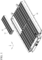
- FIG. 1 is a perspective view of a rechargeable battery pack according to embodiments of the present disclosure
- FIG. 2 is a perspective view of a pack frame of the embodiment illustrated in FIG. 1
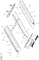
- FIG. 3 is an exploded perspective view of the pack frame of FIG. 2 .
- a rechargeable battery pack includes a plurality of cell stacks 100 and a pack frame 200 on which the cell stacks 100 are mounted.
- the pack frame 200 includes a center frame 10, a first side frame 21, a second side frame 22, and a first end frame 31 and a second end frame 32.
- the pack frame 200 may further include a lateral or cross center frame 40.
- the lateral center frame 40 is coupled to the center frame 10 and the first and second side frames 21 and 22 in an intermediate portion (e.g., the middle or substantially the middle) of the center frame 10 in the first direction (x-axis direction) to support the different cell stacks 100 on both sides of the lateral center frame 10 in the first direction (x-axis direction).
- the sizes (lengths) of the center frame 10 and the first and second side frames 21 and 22 may correspond to the size (length) of the cell stack 100 in the first direction (x-axis direction). That is, the center frame 10 and the first and second side frames 21 and 22 may be cut to an appropriate length depending on the length of the cell stack 100 in the first direction (x-axis direction).
- the center frame 10 In the pack frame 200, the center frame 10, the first side frame 21, and the second side frame 22 form an assembly space for the cell stack 100.
- the cross-sectional shape and the length of the center frame 10, and the first and second side frames 21 and 22 may be selected depending on the various energy requirements of electric vehicles that utilize the cell stacks 100.
- the center frame 10 includes a first bottom 11 and a first side wall 12 configured to support the cell stack 100.
- the first side wall 12 has a height extending upward in the third direction (z-axis direction) from the center (or substantially the center) of the first bottom 11 in the second direction (y-axis direction) and extends lengthwise in the first direction (x-axis direction). Accordingly, the center frame 10 is formed at both sides in the second direction (y-axis direction) with an open first bottom 11 without side walls.
- the first side frame 21 and the second side frame 22 are each coupled to the center frame 10 in the second direction (y-axis direction) crossing the first direction (x-axis direction), and each have a second bottom 211 and second side walls 212 and 213 to support a cell narrow side (xz plane) of the cell stacks 100.
- the first end frame 31 and the second end frame 32 are coupled to both ends (i.e., opposite ends) of the center frame 10 and the first and second side frames 21 and 22 in the first direction (x-axis direction) to support a cell wide side (yz plane) of the cell stacks 100.
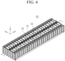
- FIG. 4 is a perspective view of a cell stack 100 in which battery cells 101 are stacked.
- the cell stack 100 is formed by stacking a plurality of battery cells 101 in the first direction (x-axis direction).
- Each of the battery cells 101 is a square rechargeable battery, has the wide cell side (yz plane) and the narrow cell side (xz plane), and includes electrode terminals 102 and 103 at the top.
- the cell wide side faces both sides of the first direction (x-axis direction).
- the cell narrow side faces both sides of the second direction (y-axis direction) orthogonal to the first direction (x-axis direction).
- the electrode terminals 102 and 103 face upward in the third direction (z-axis direction) orthogonal to the first and second directions (x- and y-axis directions).
- FIG. 5 is a cross-sectional view taken along line V-V of FIG. 4
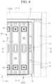
- FIG. 6 is a partial top plan view of the rechargeable battery pack of FIG. 1
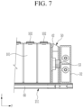
- FIG. 7 is a cross-sectional view taken along line VII-VII of FIG. 6 .
- the cell stack 100 includes insulating members 41 and 42 and a pressurizing body 50.
- the insulating members 41 and 42 are provided at both ends (i.e., opposite ends) of the cell stack 100 in the first direction and are provided on the cell wide side (yz plane) of the outermost battery cells 101 in the first direction (x-axis direction).
- the pressurizing body 50 is located outside the insulating members 41 and 42 at at least one of both ends of the cell stack 100 in the first direction, and presses (compresses) battery cells 101 of the cell stack 100 together in the first direction.
- FIG. 8 is a top plan view of the pressurizing body 50 applied to FIG. 6
- FIG. 9 is a first end view of the inner side of the pressurizing body 50 in contact with the cell stack of FIG. 8
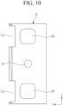
- FIG. 10 is a second end view of the outer side of the pressurizing body 50 of FIG. 8 in contact with the pack frame 200.
- the pressurizing body 50 includes a first plane portion 51 on the side of the cell stack 100, a second plane portion 52 spaced apart by a gap from the first plane portion 51, and a compressing force generator 53.
- the compressing force generator 53 is supported on the end frame 32 by screwing the compressing force generator 53 into the second plane portion 52 so that the first plane portion 51 presses the cell stack 100.
- the compressing force generator 53 is a bolt.
- the bolt head of the compressing force generator 53 is between the first and second plane portions 51 and 52 and is rotationally adjustable.
- the end of the compressing force generator 53 that is screwed into the second plane portion 52 is supported on the end frame 32. As the amount of protrusion of the end of the compressing force generator 53 toward the second plane portion 52 increases, the first plane portion 51 applies more compressing force to the cell stack 100.
- the cell stack assembly space is larger than the dimensions of the cell stack 100, and the cell stack 100 is assembled in the cell stack assembly space in an uncompressed state.
- the pressurizing body 50 configured to compress the cell stack 100 is located on at least one side of the cell stack 100 in the first direction.
- the pressurizing body 50 moves in a direction opposite to that of the compressing force generator 53 and compresses the cell stack 100. Compressing the cell stack 100 adjusts the overall dimensions of the cell stack 100 in the first direction and enables the welding of a bus bar 104 (see FIG. 12 ) to the cell stack 100.
- Compressing the cell stack 100 is performed by rotating the compressing force generator 53 of the pressurizing body 50 after the cell stack 100 is assembled to the pack frame 200. After assembly and compressing all cell stacks 100 are completed, the bus bars 104 are laser welded to the electrode terminals 102 and 103 of the battery cells 101.
- the compressing force generator 53 of the defective cell stack 100 may be released so that only the corresponding cell stack 100 may be reworked (e.g., the laser welding may be reperformed). Accordingly, the rechargeable battery pack of embodiments allows the cell stack 100 to be reworked when a defect occurs during the process.
- Rotating the compressing force generator 53 causes the pressurizing body 50 to compress the battery cells 100.
- the compressing force may be adjusted in various ways by adjusting the bolt exterior diameter, material, and torque value of the compressing force generator 53.
- Equation 1 The relationship between the torque applied to the compressing force generator 53 (e.g., the bolt), and the axial force of the compressing force generator 53 may be calculated as shown in Equation 1.
- F T / Kd 1 ⁇ L / 100
- Equation 1 F is the axial bolt force (compressing force) (N), T is the wrench torque (Nm), K is a constant that varies depending on the material and size, d is the nominal bolt diameter (m), and L is the lubrication coefficient (%).
- the compressing force is approximately 2500N.
- the compressing force may be applied to the cell stack 100 by applying various variable values of the compressing force generator (e.g., bolt).
- the position of the compressing force generator 53 with respect to the pressurizing body 50 may be specified.
- the first plane portion 51 is formed with an area corresponding to the cell wide side (yz plane) of the cell stack 100.
- the second plane portion 52 has a smaller area than the first plane portion 51.
- the pressurizing body 50 further includes an inclined surface portion 54 connecting the first plane portion 51 and the second plane portion 52 in a direction inclined with respect to the first direction (x-axis direction).
- the pressurizing body 50 further includes a rib 55 connecting the first plane portion 51 and the second plane portion 52 in the first direction (x-axis direction).
- the inclined surface portion 54 and the rib 55 strengthen the mechanical strength of the pressurizing body 50 and prevent (or at least mitigate) deformation when the compressing force is transmitted from the second plane portion 52 to the first plane portion 51.
- first plane portion 51 and the second plane portion 52 include recess portions 511 and 521 (e.g., notches), respectively, that are partially cut at the portion where the electrode terminals 102 and 103 of the battery cell 101 are located.
- the recess portions 511 and 521 prevent or at least reduce strong compressing forces from being applied to the electrode terminals 102 and 103, which are structurally more complex and vulnerable portions of the battery cell 101 than the portion including an electrode assembly (not shown).
- first plane portion 51 has a first vent hole 512
- second plane portion 52 has second vent holes 522 on both sides of the compressing force generator 53 and connected to the first vent hole 512.
- the position of the compressing force generator 53 is at the center (or approximately the center) of the first and second plane portions 51 and 52 of the pressurizing body 50 to apply a uniform (or approximately uniform) compressing force and does not protrude above the contact surface of the cell stack 100.
- a compressible distance CL of the compressing force generator 53 is the distance between the lower end of the bolt head and the inner surface of the second plane portion 52.
- the maximum compression requirement is 7 mm, it may be designed as follows.
- the battery cell 101 may move during cell swelling, vibration, or impact, which may cause a fire or explosion.
- side bonding is applied to both sides of the cell stack 100 in the second direction (x-axis direction).
- the gap portion 223 is connected to the inclined portion 222 to form a gap that induces or guides the adhesive to flow downward from the cell narrow side (xz plane) of the battery cells 101 and the cell bottom (xy plane) of the battery cells 101.
- the gap portion 223 is filled with adhesive 224 at the cell bottom (xy plane) and the cell narrow side (xz plane) adjacent to the cell bottom.
- the filled adhesive 224 has a length (L) set at the cell bottom (xy plane) and a height (H) set at the cell narrow side (xz plane).
- the adhesive 224 attaches the battery cells 101 of the cell stack 100 to the first and second side frames 21 and 22.
- An L-shaped insulation 214 with a length (L) and height (H) may be applied to the side and bottom surfaces of the cell stack 100 to form a space for adhesive to flow between the cell stack 100 and the second side walls 212 and 213, and between the cell stack 100 and the second bottom 211.
- the cell stack 100 is prevented from being assembled eccentrically (i.e., crooked) between the second side walls 212 and 213, and a minimum space equal to the thickness of the insulation 214 may be achieved.
- the adhesive flows down and is absorbed into the insulation 214.
- the adhesive has a viscosity capable of providing adhesion with the insulation 214.
- the side bonding of the cell stack 100 may be achieved.
- An inclination angle ⁇ of the inclined portion 222 for applying the adhesive may be adjusted depending on the viscosity of the adhesive.
- the inclination angle ⁇ may be larger for a relatively low-viscosity adhesive, and the inclination angle ⁇ may be smaller for a relatively high-viscosity adhesive.
- a gap GG between the battery cell 101 and the second side walls 212 and 213 for adhesive application may be adjusted depending on the viscosity of the adhesive, and may be adjusted by adjusting the length (L) and height (H) of the insulation 214. That is, the gap GG may be larger for a relatively high-viscosity adhesive, and the gap GG may be smaller for a relatively low-viscosity adhesive.
- the inclination angle ⁇ may be in a range from approximately 40° to approximately 50°, and the gap GG may be in a range from approximately 1.0 mm to approximately 2.0 mm. In one or more embodiments, the inclination angle ⁇ may be approximately 45° and the gap GG may be approximately 1.5 mm.
- the inclination angle ⁇ may be in a range from approximately 25° to approximately 35°, and the gap GG may be in a range from approximately 2.0 mm to approximately 3.0 mm. In one or more embodiments, the inclination angle ⁇ may be approximately 30° and the gap GG may be approximately 2.5 mm.
- the first and second side frames 21 and 22 may have the adhesive injection port 221, the inclined portion 222, and the inductive gap portion 223 on one of the second side walls 212 and 213 in the second direction (y-axis direction).
- the adhesive injection port 221, the inclined portion 222, and the gap portion 223 may be provided on each of the second side walls 212 and 213 in the second direction (y-axis direction) to provide a stronger adhesion with the battery cells 101.
- the center frame 10 may include an adhesive injection port 121, an inclined portion 122, and a gap portion 124 on the first side wall 12.
- first side wall 12 of the center frame 10 corresponds to the second side wall 213 of the first and second side frames 21 and 22
- a separate illustration of the first side wall 12 of the center frame 10 will be omitted, and will be described by the adhesive injection port 121, the first inclined portion 122 and the second inclined portion 123, and the first gap portion 124 and a second gap portion 125 provided in the second side wall 213 of the first and second side frames 21 and 22 of FIG. 11 .
- the adhesive injection port 121 is provided at the top in the third direction (z-axis direction) to enable injection of adhesive.
- the first inclined portion 122 and the second inclined portion 123 are connected to the adhesive injection port 121 and are formed to be inclined inward and outward in the second direction, respectively.
- the first gap portion 124 and the second gap portion 125 are connected to the first inclined portion 122 and the second inclined portion 123, respectively, and induce or guide the flow of the adhesive to each cell narrow side (xz plane) of the battery cells 101 on both sides of the first side wall 12 of the center frame 10 in the second direction.
- the first gap portion 124 and the second gap portion 125 are filled (or substantially filled) with the adhesive 224 at the cell bottom (xy plane) and the cell narrow side (xz plane) of the battery cells 101 adjacent to the cell bottom.
- the first and second side frames 21 and 22 include the adhesive injection port 121, the first inclined portion 122 and the second inclined portion 123, and the first gap portion 124 and the second gap portion 125 on the second side wall 213.
- the first gap portion 124 and the second gap portion 125 are filled (or substantially filled) with the adhesive 224 at the cell bottom (xy plane) and the cell narrow side (xz plane) of the battery cells 101 adjacent to the cell bottom.
- a first insulation 245 and a second insulation 246 are located between the inside of the side wall 12 and the cell stack 100 in the second direction and between the outside of the side wall 12 and the cell stack 100 in the second direction, respectively.
- the first insulation 245 and the second insulation 246 each have an L-shaped cross-section with the length (L) and the height (H) of the first and second insulations 245, 246 on the side and bottom surfaces of the cell stack 100 to provide a space for the adhesive to flow.
- FIG. 12 is a partial cross-sectional view of a pack cover 300 assembled to the rechargeable battery pack of FIG. 1
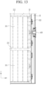
- FIG. 13 is a cross-sectional view taken along line XIII - XIII of FIG. 12 .
- the rechargeable battery pack according to embodiments of the present disclosure further include a pack cover 300 mounted on the first and second side frames 21 and 22 and on the first and second end frames 31 and 32.
- the pack cover 300 covers the bus bar 104 that electrically connects the electrode terminals 102 and 103 of the battery cells 101 together.
- at least one of the first and second end frames 31 and 32 includes a pack vent 400 connected to a second vent hole 522.
- the gap G1 between the busbar 104 and the pack cover 300 is connected to (in fluid communication with) the gap G2 set between the first plane portion 51 of the pressurizing body 50 and the first plane portion 51.
- These gaps G1 and G2, together with the recess portions 511 and 521 and the first and second vent holes 512 and 522, enable the discharge of gas generated from the battery cells 101 during an event. This gas may be safely discharged to the outside of the rechargeable battery pack through the pack vent 400 provided in the second end frame 32 via the third vent hole 322 in the second end frame 32.
- first and second side frames 21 and 22 further include flanges 216 and 226, respectively, extending lengthwise along the first direction (x-axis direction) and extending outward in the second direction (y-axis direction).
- the flanges 216 and 226 are configured to be mounted on the vehicle.
- first bottom 11 of the center frame 10 and the second bottom 211 of each of the first and second side frames 21 and 22 form a plurality of refrigerant passages 60 (see FIGS. 11 and 12 ).
- a refrigerant circulating through the refrigerant passages 60 is configured to cool the battery cells 101.
- the refrigerant passages 60 are connected to each other at both ends in the first direction, and are connected to a refrigerant inlet 61 and a refrigerant outlet 62 provided at one end of the rechargeable battery pack in the first direction and spaced apart from each other along the second direction.
Landscapes
- Chemical & Material Sciences (AREA)
- Chemical Kinetics & Catalysis (AREA)
- Electrochemistry (AREA)
- General Chemical & Material Sciences (AREA)
- Engineering & Computer Science (AREA)
- Manufacturing & Machinery (AREA)
- Aviation & Aerospace Engineering (AREA)
- Battery Mounting, Suspending (AREA)
Abstract
A rechargeable battery pack that maximizes pack energy density by stacking battery cells. A rechargeable battery pack includes a center frame having a first bottom and a first side wall and supporting the cell stack, a first side frame and a second side frame having a second bottom and a second side wall and coupled to the center frame in a second direction crossing the first direction and supporting a cell narrow side of the cell stack, and a first end frame and a second end frame coupled to both ends of the center frame, the first side frame, and the second side frame in the first direction to support a cell wide side of the cell stack.
Description
- The present disclosure relates to a rechargeable battery pack.
- Unlike primary batteries, rechargeable batteries are batteries that repeatedly charge and discharge. Small-capacity rechargeable batteries are used in small, portable electronic devices such as mobile phones, laptop computers, and camcorders. High-capacity and high-density secondary batteries are used as power sources for driving motors in hybrid and electric vehicles or for energy storage.
- A rechargeable battery module may include a plurality of battery cells connected in series and/or parallel to drive a motor of, for example, a hybrid vehicle that requires relatively high energy density. For example, a rechargeable battery module may be formed by stacking a plurality of battery cells in a frame and the number of battery cells may depend on a desired amount of power of the rechargeable battery module (e.g., for an electric vehicle).
- Such rechargeable battery modules are connected in series and/or parallel within a housing manufactured using various methods to form a rechargeable battery pack. Therefore, various types of rechargeable battery modules are being manufactured to suit the capacity of the rechargeable battery pack.
- However, in terms of energy capacity, packs with rechargeable battery modules have limitations. Therefore, in order to maximize the energy of the rechargeable battery pack, it is desirable to manufacture a rechargeable battery pack that directly assembles the battery cells without a rechargeable battery module.
- The above information disclosed in this Background section is for enhancement of understanding of the background of the present disclosure, and therefore, it may contain information that does not constitute prior art.
- Embodiments of the present disclosure relates to a rechargeable battery pack that maximizes or at least increases pack energy density by stacking battery cells.
- A rechargeable battery pack according to embodiments of the present disclosure includes a center frame supporting the cell stack with a first bottom and a first side wall, a first side frame and a second side frame coupled to the center frame in a second direction crossing the first direction and having a second bottom and a second side wall to support a cell narrow side of the cell stack, and a first end frame and a second end frame coupled to both ends of the center frame, the first side frame, and the second side frame in the first direction to support a cell wide side of the cell stack.
- The rechargeable battery pack according to embodiments of the present disclosure may further include a cross center frame coupled to the center frame, the first side frame, and the second side frame in the middle of the first direction to support the cell wide sides of the different cell stacks on both sides of the first direction.
- The center frame, the first side frame, and the second side frame may correspond to various sizes of the cell stack depending on the length in the first direction.
- The cell stack may include insulating members provided at both ends of the first direction, and a pressurizing body disposed outside the insulating member at at least one side of both ends in the first direction.
- The pressurizing body may include a first plane portion disposed on the cell stack side, a second plane portion formed integrally with the first plane portion to form a gap, and a compressing force generator supported on the end frame by screwing the second plane portion and causing the first plane portion to press the cell stack.
- The first plane portion is formed with an area corresponding to the cell wide side of the cell stack, the second plane portion is formed to have a smaller area than the first plane portion, and the pressurizing body may further include an inclined surface portion connecting the first plane portion and the second plane portion in a direction inclined to the first direction.
- The pressurizing body may further include a rib connecting the first plane portion and the second plane portion in the first direction.
- The first plane portion and the second plane portion may have a partially cut recess portion at a portion where the electrode terminals of the battery cell are disposed.
- The first flat part may have a first vent hole, and the second plane portion may have second vent holes penetrating on both sides of the compressing force generator and connected to the first vent hole.
- The rechargeable battery pack may further include a pack cover mounted on the first side frame, the second side frame, and the first end frame and the second end frame, wherein at least one of the first end frame and the second end frame has a pack vent connected to the second vent hole.
- The first side frame and the second side frame may have an adhesive injection port provided at the top of the third direction, an inclined portion connected to the adhesive injection port and inclined inward in the second direction, and an inductive gap portion connected to the inclined portion to form a gap that guides adhesive to the cell narrow side and a cell bottom of the battery cell. The inductive gap may be filled with an adhesive.
- The rechargeable battery pack of embodiments of the present disclosure may be provided between the second side wall and the cell stack and may further include insulation having a length (L) and a height (H) on the side and bottom surfaces of the cell stack.
- The first side frame and the second side frame may have the adhesive injection port, the inclined portion, and the inductive gap portion on at least one side in the second direction.
- The center frame may include an adhesive injection port provided at the top of the third direction, a first inclined portion and a second inclined portion connected to the adhesive injection port and inclined respectively inward and outward in the second direction, and a first inductive gap portion and a second inductive gap portion respectively connected to the first inclined portion and the second inclined portion and respectively induce the adhesive to the cell narrow side of the battery cell disposed on both sides in the second direction. The first inductive gap portion and the second inductive gap portion may be filled with an adhesive.
- The rechargeable battery pack according to embodiments of the present disclosure may be provided between the inner side of the side wall in the second direction and the cell stack and between the outer side of the side wall in the second direction and the cell stack, and may further include a first insulation and a second insulation having a length (L) and a height (H) on the side and bottom surfaces of the cell stack.
- The first side frame and the second side frame may have the adhesive injection port, the first inclined portion and the second inclined portion, and the first inductive gap portion and the second inductive gap portion on at least one side in the second direction.
- The first side frame and the second side frame may include a flange that is formed to be long along the first direction at the outer edge of the second direction and is mounted on a vehicle.
- The first bottom and the second bottom may form refrigerant passages, and the refrigerant passages may be connected to each other at both ends in the first direction, and may be connected to a refrigerant inlet and a refrigerant outlet provided at both ends of the second direction at one end of the first direction.
- At least some of the above and other features of the invention are set out in the claims.
- The rechargeable battery pack of embodiments is equipped with a cell stack that stacks a plurality of battery cells in a first direction with a center frame, first and second side frames, and first and second end frames, so that pack energy density may be maximized or at least increased.
- According to embodiments, the center frame, first and second side frames may correspond to various sizes of the cell stack depending on the length in the first direction. Additionally, because embodiments include a pressurizing body in the cell stack, the cell stack may be pressed in the first direction.
-
-
FIG. 1 is a perspective view of a rechargeable battery pack according to embodiments of the present disclosure. -
FIG. 2 is a perspective view of a pack frame of the embodiment of the rechargeable battery pack illustrated inFIG. 1 . -
FIG. 3 is an exploded perspective view of the pack frame ofFIG. 2 . -
FIG. 4 is a perspective view of a cell stack of the embodiment of the rechargeable battery pack illustrated inFIG. 1 in which battery cells are stacked. -
FIG. 5 is a cross-sectional view taken along line V-V ofFIG. 4 . -
FIG. 6 is a partial top plan view of the rechargeable battery pack ofFIG. 1 . -
FIG. 7 is a cross-sectional view taken along line VII-VII ofFIG. 6 . -
FIG. 8 is a top plan view of the pressurizing body applied toFIG. 6 . -
FIG. 9 is a first top plan view of the inner side in contact with the cell stack of the pressurizing body ofFIG. 8 . -
FIG. 10 is a second top plan view of the outer side of the pressurizing body ofFIG. 8 in contact with the pack frame. -
FIG. 11 is a cross-sectional view taken along line XI-XI ofFIG. 6 . -
FIG. 12 is a partial cross-sectional view of a pack cover assembled to the rechargeable battery pack ofFIG. 1 . -
FIG. 13 is a cross-sectional view taken along line XIII - XIII ofFIG. 12 . - Hereinafter, the present invention will be described more fully hereinafter with reference to the accompanying drawings, in which embodiments of the invention are shown. As those skilled in the art would realize, the described embodiments may be modified in various different ways, all without departing from the scope of the present invention. The drawings and description are to be regarded as illustrative in nature and not restrictive. Like reference numerals designate like elements throughout the specification.
-
FIG. 1 is a perspective view of a rechargeable battery pack according to embodiments of the present disclosure,FIG. 2 is a perspective view of a pack frame of the embodiment illustrated inFIG. 1 , andFIG. 3 is an exploded perspective view of the pack frame ofFIG. 2 . - Referring to
FIGS. 1 to 3 , a rechargeable battery pack according to embodiments of the present disclosure includes a plurality ofcell stacks 100 and apack frame 200 on which thecell stacks 100 are mounted. Thepack frame 200 includes acenter frame 10, afirst side frame 21, asecond side frame 22, and afirst end frame 31 and asecond end frame 32. - In an embodiment in which the
pack frame 200 is configured to extend lengthwise in the first direction (x-axis direction), thepack frame 200 may further include a lateral orcross center frame 40. Thelateral center frame 40 is coupled to thecenter frame 10 and the first andsecond side frames center frame 10 in the first direction (x-axis direction) to support thedifferent cell stacks 100 on both sides of thelateral center frame 10 in the first direction (x-axis direction). - The sizes (lengths) of the
center frame 10 and the first andsecond side frames cell stack 100 in the first direction (x-axis direction). That is, thecenter frame 10 and the first andsecond side frames cell stack 100 in the first direction (x-axis direction). - In the
pack frame 200, thecenter frame 10, thefirst side frame 21, and thesecond side frame 22 form an assembly space for thecell stack 100. - The cross-sectional shape and the length of the
center frame 10, and the first and second side frames 21 and 22 may be selected depending on the various energy requirements of electric vehicles that utilize the cell stacks 100. - The
center frame 10 includes a first bottom 11 and afirst side wall 12 configured to support thecell stack 100. Thefirst side wall 12 has a height extending upward in the third direction (z-axis direction) from the center (or substantially the center) of the first bottom 11 in the second direction (y-axis direction) and extends lengthwise in the first direction (x-axis direction). Accordingly, thecenter frame 10 is formed at both sides in the second direction (y-axis direction) with an open first bottom 11 without side walls. - The
first side frame 21 and thesecond side frame 22 are each coupled to thecenter frame 10 in the second direction (y-axis direction) crossing the first direction (x-axis direction), and each have asecond bottom 211 andsecond side walls - The
first end frame 31 and thesecond end frame 32 are coupled to both ends (i.e., opposite ends) of thecenter frame 10 and the first and second side frames 21 and 22 in the first direction (x-axis direction) to support a cell wide side (yz plane) of the cell stacks 100. -
FIG. 4 is a perspective view of acell stack 100 in whichbattery cells 101 are stacked. Referring toFIGS. 1 and4 , thecell stack 100 is formed by stacking a plurality ofbattery cells 101 in the first direction (x-axis direction). - Before being mounted on the
pack frame 200, thecell stack 100 is in an uncompressed state. Each of thebattery cells 101 is a square rechargeable battery, has the wide cell side (yz plane) and the narrow cell side (xz plane), and includeselectrode terminals - In the
battery cell 101, the cell wide side (yz plane) faces both sides of the first direction (x-axis direction). The cell narrow side (xz plane) faces both sides of the second direction (y-axis direction) orthogonal to the first direction (x-axis direction). Theelectrode terminals -
FIG. 5 is a cross-sectional view taken along line V-V ofFIG. 4 ,FIG. 6 is a partial top plan view of the rechargeable battery pack ofFIG. 1 , andFIG. 7 is a cross-sectional view taken along line VII-VII ofFIG. 6 . - Referring to
FIGS. 4 to 7 , thecell stack 100 includes insulatingmembers body 50. The insulatingmembers cell stack 100 in the first direction and are provided on the cell wide side (yz plane) of theoutermost battery cells 101 in the first direction (x-axis direction). The pressurizingbody 50 is located outside the insulatingmembers cell stack 100 in the first direction, and presses (compresses)battery cells 101 of thecell stack 100 together in the first direction. -
FIG. 8 is a top plan view of the pressurizingbody 50 applied toFIG. 6 ,FIG. 9 is a first end view of the inner side of the pressurizingbody 50 in contact with the cell stack ofFIG. 8 , andFIG. 10 is a second end view of the outer side of the pressurizingbody 50 ofFIG. 8 in contact with thepack frame 200. - Referring to
FIGS. 6 to 10 , the pressurizingbody 50 includes afirst plane portion 51 on the side of thecell stack 100, asecond plane portion 52 spaced apart by a gap from thefirst plane portion 51, and a compressingforce generator 53. - The compressing
force generator 53 is supported on theend frame 32 by screwing the compressingforce generator 53 into thesecond plane portion 52 so that thefirst plane portion 51 presses thecell stack 100. In one or more embodiments, the compressingforce generator 53 is a bolt. - The bolt head of the compressing
force generator 53 is between the first andsecond plane portions force generator 53 that is screwed into thesecond plane portion 52 is supported on theend frame 32. As the amount of protrusion of the end of the compressingforce generator 53 toward thesecond plane portion 52 increases, thefirst plane portion 51 applies more compressing force to thecell stack 100. - In one or more embodiments, the cell stack assembly space is larger than the dimensions of the
cell stack 100, and thecell stack 100 is assembled in the cell stack assembly space in an uncompressed state. The pressurizingbody 50 configured to compress thecell stack 100 is located on at least one side of thecell stack 100 in the first direction. - In response to the compressing
force generator 53 being rotated, the pressurizingbody 50 moves in a direction opposite to that of the compressingforce generator 53 and compresses thecell stack 100. Compressing thecell stack 100 adjusts the overall dimensions of thecell stack 100 in the first direction and enables the welding of a bus bar 104 (seeFIG. 12 ) to thecell stack 100. - Compressing the
cell stack 100 is performed by rotating the compressingforce generator 53 of the pressurizingbody 50 after thecell stack 100 is assembled to thepack frame 200. After assembly and compressing allcell stacks 100 are completed, the bus bars 104 are laser welded to theelectrode terminals battery cells 101. - In an event in which a laser welding defect occurs, the compressing
force generator 53 of thedefective cell stack 100 may be released so that only thecorresponding cell stack 100 may be reworked (e.g., the laser welding may be reperformed). Accordingly, the rechargeable battery pack of embodiments allows thecell stack 100 to be reworked when a defect occurs during the process. - Rotating the compressing
force generator 53 causes the pressurizingbody 50 to compress thebattery cells 100. The compressing force may be adjusted in various ways by adjusting the bolt exterior diameter, material, and torque value of the compressingforce generator 53. - The relationship between the torque applied to the compressing force generator 53 (e.g., the bolt), and the axial force of the compressing
force generator 53 may be calculated as shown in Equation 1.
- In Equation 1, F is the axial bolt force (compressing force) (N), T is the wrench torque (Nm), K is a constant that varies depending on the material and size, d is the nominal bolt diameter (m), and L is the lubrication coefficient (%).
- In an embodiment in which T=10Nm, K=0.2 (zinc plated), d=0.02m (∅20mm), and L=0%, the compressing force is approximately 2500N. The compressing force may be applied to the
cell stack 100 by applying various variable values of the compressing force generator (e.g., bolt). - In one or more embodiments, the position of the compressing
force generator 53 with respect to the pressurizingbody 50 may be specified. In the pressurizingbody 50, thefirst plane portion 51 is formed with an area corresponding to the cell wide side (yz plane) of thecell stack 100. In one or more embodiments, thesecond plane portion 52 has a smaller area than thefirst plane portion 51. - The pressurizing
body 50 further includes aninclined surface portion 54 connecting thefirst plane portion 51 and thesecond plane portion 52 in a direction inclined with respect to the first direction (x-axis direction). The pressurizingbody 50 further includes arib 55 connecting thefirst plane portion 51 and thesecond plane portion 52 in the first direction (x-axis direction). Theinclined surface portion 54 and therib 55 strengthen the mechanical strength of the pressurizingbody 50 and prevent (or at least mitigate) deformation when the compressing force is transmitted from thesecond plane portion 52 to thefirst plane portion 51. - In addition, the
first plane portion 51 and thesecond plane portion 52 includerecess portions 511 and 521 (e.g., notches), respectively, that are partially cut at the portion where theelectrode terminals battery cell 101 are located. Therecess portions electrode terminals battery cell 101 than the portion including an electrode assembly (not shown). - In addition, the
first plane portion 51 has afirst vent hole 512, and thesecond plane portion 52 has second vent holes 522 on both sides of the compressingforce generator 53 and connected to thefirst vent hole 512. - The position of the compressing
force generator 53 is at the center (or approximately the center) of the first andsecond plane portions body 50 to apply a uniform (or approximately uniform) compressing force and does not protrude above the contact surface of thecell stack 100. - A compressible distance CL of the compressing
force generator 53 is the distance between the lower end of the bolt head and the inner surface of thesecond plane portion 52. In one or more embodiments in which the maximum compression requirement is 7 mm, it may be designed as follows. - Wrench work is possible at a gap G2 set between the first and second
flat portions body 50. In order to prevent (or at least mitigate) stress from concentrating on thesecond plane portion 52 and to apply uniform (or approximately uniform) compressing force, the bolt diameter may be made as large as possible within a range that does not cause issues with assembly. - Once the assembly of the
cell stack 100 on thepack frame 10 and the laser welding of thebus bar 104 are completed, additional fixation of thecell stack 100 may be performed. If thecell stack 100 is not completely fixed, thebattery cell 101 may move during cell swelling, vibration, or impact, which may cause a fire or explosion. In one or more embodiments, after thecell stack 100 is assembled, side bonding is applied to both sides of thecell stack 100 in the second direction (x-axis direction). -
FIG. 11 is a cross-sectional view taken along line XI-XI ofFIG. 6 . Referring toFIG. 11 , the first and second side frames 21 and 22 each include anadhesive injection port 221, aninclined portion 222, and agap portion 223 on thesecond side walls - The
adhesive injection port 221 is provided at the top in the third direction (z-axis direction) to enable injection of adhesive. Theinclined portion 222 is connected to theadhesive injection port 221 and is inclined inward in the second direction (y-axis direction). Theinclined portion 222 is configured to allow the injected adhesive to flow downward. - The
gap portion 223 is connected to theinclined portion 222 to form a gap that induces or guides the adhesive to flow downward from the cell narrow side (xz plane) of thebattery cells 101 and the cell bottom (xy plane) of thebattery cells 101. Thegap portion 223 is filled with adhesive 224 at the cell bottom (xy plane) and the cell narrow side (xz plane) adjacent to the cell bottom. - The filled adhesive 224 has a length (L) set at the cell bottom (xy plane) and a height (H) set at the cell narrow side (xz plane). The adhesive 224 attaches the
battery cells 101 of thecell stack 100 to the first and second side frames 21 and 22. - An L-shaped
insulation 214 with a length (L) and height (H) may be applied to the side and bottom surfaces of thecell stack 100 to form a space for adhesive to flow between thecell stack 100 and thesecond side walls cell stack 100 and thesecond bottom 211. - In this manner, the
cell stack 100 is prevented from being assembled eccentrically (i.e., crooked) between thesecond side walls insulation 214 may be achieved. The adhesive flows down and is absorbed into theinsulation 214. In one or more embodiments, the adhesive has a viscosity capable of providing adhesion with theinsulation 214. - The side bonding of the
cell stack 100 may be achieved. An inclination angle θ of theinclined portion 222 for applying the adhesive may be adjusted depending on the viscosity of the adhesive. In one or more embodiments, the inclination angle θ may be larger for a relatively low-viscosity adhesive, and the inclination angle θ may be smaller for a relatively high-viscosity adhesive. - A gap GG between the
battery cell 101 and thesecond side walls insulation 214. That is, the gap GG may be larger for a relatively high-viscosity adhesive, and the gap GG may be smaller for a relatively low-viscosity adhesive. - In one or more embodiments in which the adhesive has a viscosity of 5000 cps, the inclination angle θ may be in a range from approximately 40° to approximately 50°, and the gap GG may be in a range from approximately 1.0 mm to approximately 2.0 mm. In one or more embodiments, the inclination angle θ may be approximately 45° and the gap GG may be approximately 1.5 mm.
- In an embodiment in which the adhesive has a viscosity of approximately 10000 cps, the inclination angle θ may be in a range from approximately 25° to approximately 35°, and the gap GG may be in a range from approximately 2.0 mm to approximately 3.0 mm. In one or more embodiments, the inclination angle θ may be approximately 30° and the gap GG may be approximately 2.5 mm.
- The first and second side frames 21 and 22 may have the
adhesive injection port 221, theinclined portion 222, and theinductive gap portion 223 on one of thesecond side walls adhesive injection port 221, theinclined portion 222, and thegap portion 223 may be provided on each of thesecond side walls battery cells 101. - Referring to
FIG. 11 , thecenter frame 10 may include anadhesive injection port 121, aninclined portion 122, and agap portion 124 on thefirst side wall 12. - Because the
first side wall 12 of thecenter frame 10 corresponds to thesecond side wall 213 of the first and second side frames 21 and 22, a separate illustration of thefirst side wall 12 of thecenter frame 10 will be omitted, and will be described by theadhesive injection port 121, the firstinclined portion 122 and the secondinclined portion 123, and thefirst gap portion 124 and asecond gap portion 125 provided in thesecond side wall 213 of the first and second side frames 21 and 22 ofFIG. 11 . - The
adhesive injection port 121 is provided at the top in the third direction (z-axis direction) to enable injection of adhesive. The firstinclined portion 122 and the secondinclined portion 123 are connected to theadhesive injection port 121 and are formed to be inclined inward and outward in the second direction, respectively. - The
first gap portion 124 and thesecond gap portion 125 are connected to the firstinclined portion 122 and the secondinclined portion 123, respectively, and induce or guide the flow of the adhesive to each cell narrow side (xz plane) of thebattery cells 101 on both sides of thefirst side wall 12 of thecenter frame 10 in the second direction. Thefirst gap portion 124 and thesecond gap portion 125 are filled (or substantially filled) with the adhesive 224 at the cell bottom (xy plane) and the cell narrow side (xz plane) of thebattery cells 101 adjacent to the cell bottom. - The first and second side frames 21 and 22 include the
adhesive injection port 121, the firstinclined portion 122 and the secondinclined portion 123, and thefirst gap portion 124 and thesecond gap portion 125 on thesecond side wall 213. - In the first and second side frames 21 and 22, the
first gap portion 124 and thesecond gap portion 125 are filled (or substantially filled) with the adhesive 224 at the cell bottom (xy plane) and the cell narrow side (xz plane) of thebattery cells 101 adjacent to the cell bottom. - A
first insulation 245 and asecond insulation 246 are located between the inside of theside wall 12 and thecell stack 100 in the second direction and between the outside of theside wall 12 and thecell stack 100 in the second direction, respectively. Thefirst insulation 245 and thesecond insulation 246 each have an L-shaped cross-section with the length (L) and the height (H) of the first andsecond insulations cell stack 100 to provide a space for the adhesive to flow. -
FIG. 12 is a partial cross-sectional view of apack cover 300 assembled to the rechargeable battery pack ofFIG. 1 , andFIG. 13 is a cross-sectional view taken along line XIII - XIII ofFIG. 12 . Referring toFIGS. 12 and13 , the rechargeable battery pack according to embodiments of the present disclosure further include apack cover 300 mounted on the first and second side frames 21 and 22 and on the first and second end frames 31 and 32. - The
pack cover 300 covers thebus bar 104 that electrically connects theelectrode terminals battery cells 101 together. In one or more embodiments, at least one of the first and second end frames 31 and 32 includes apack vent 400 connected to asecond vent hole 522. - The gap G1 between the
busbar 104 and thepack cover 300 is connected to (in fluid communication with) the gap G2 set between thefirst plane portion 51 of the pressurizingbody 50 and thefirst plane portion 51. These gaps G1 and G2, together with therecess portions battery cells 101 during an event. This gas may be safely discharged to the outside of the rechargeable battery pack through thepack vent 400 provided in thesecond end frame 32 via thethird vent hole 322 in thesecond end frame 32. - Referring again to
FIG. 3 , the first and second side frames 21 and 22 further includeflanges flanges - In addition, the
first bottom 11 of thecenter frame 10 and thesecond bottom 211 of each of the first and second side frames 21 and 22 form a plurality of refrigerant passages 60 (seeFIGS. 11 and12 ). A refrigerant circulating through therefrigerant passages 60 is configured to cool thebattery cells 101. Therefrigerant passages 60 are connected to each other at both ends in the first direction, and are connected to arefrigerant inlet 61 and arefrigerant outlet 62 provided at one end of the rechargeable battery pack in the first direction and spaced apart from each other along the second direction. - While this disclosure has been described in connection with what is presently considered to be practical embodiments, it is to be understood that the disclosure is not limited to the disclosed embodiments, but, on the contrary, is intended to cover various modifications and equivalent arrangements included within the scope of the appended claims.
<Description of symbols> 10: Center frame 11: First bottom 12: First side wall 21: First side frame 22: Second side frame 31: First end frame 32: Second end frame 40: Cross center frame 41, 42: Insulating member 50: Pressurizing body 51: First plane portion 52: Second plane portion 53: Compressing force generator 54: Inclined surface portion 55: Rib 60: Refrigerant passage 61: Refrigerant inlet 62: Refrigerant outlet 100: Cell stack 101: Battery cell 102, 103: Electrode terminal 104: Bus bar 121: Adhesive injection port 122: Inclined portion 123: Inductive gap portion 124: First inductive gap portion 125: Second inductive gap portion 200: Pack frame 211: Second bottom 212, 213: Second side wall 214: Insulation 216, 226: Flange 221: Adhesive injection port 222: Inclined portion 223: Inductive gap portion 224: Adhesive 245: First insulation 246: Second insulation 300: Pack Cover 400: Pack Vent 511, 521: Recess portion 5 12: First vent hole 522, 322: Second, third vent hole G1: gap G2: Gap GG: Gap H: Height L: Length θ: Tilt angle - The present invention will now be defined with reference to the following clauses.
- Clause 1. A rechargeable battery pack, comprising:
- a cell stack in which a plurality of battery cells are stacked in a first direction;
- a center frame having a first bottom and a first side wall and supporting the cell stack;
- a first side frame and a second side frame having a second bottom and a second side wall and coupled to the center frame in a second direction crossing the first direction and supporting a cell narrow side of the cell stack; and
- a first end frame and a second end frame coupled to both ends of the center frame, the first side frame, and the second side frame in the first direction to support a cell wide side of the cell stack.
-
Clause 2. The rechargeable battery pack according to clause 1, further comprising: a cross center frame coupled to the center frame, the first side frame, and the second side frame in the middle of the first direction to support the cell wide sides of the different cell stacks on both sides of the first direction. - Clause 3. The rechargeable battery pack according to clause 1 or
clause 2, wherein the center frame, the first side frame, and the second side frame correspond to various sizes of the cell stack depending on the length in the first direction. - Clause 4. The rechargeable battery pack according to any one of clauses 1 to 3, wherein the cell stack comprises insulating members provided at both ends of the first direction; and a pressurizing body disposed outside the insulating member at at least one side of both ends in the first direction.
- Clause 5. The rechargeable battery pack according to clause 4, wherein the pressurizing body comprises a first plane portion disposed on the cell stack side; a second plane portion formed integrally with the first plane portion to form a gap; and a compressing force generator supported on the end frame by screwing the second plane portion and causing the first plane portion to press the cell stack.
- Clause 6. The rechargeable battery pack according to clause 4 or clause 5, wherein the first plane portion is formed with an area corresponding to the cell wide side of the cell stack, the second plane portion is formed to have a smaller area than the first plane portion, and the pressurizing body further comprises an inclined surface portion connecting the first plane portion and the second plane portion in a direction inclined to the first direction.
- Clause 7. The rechargeable battery pack according to clause 6, wherein the pressurizing body further comprises a rib connecting the first plane portion and the second plane portion in the first direction.
- Clause 8. The rechargeable battery pack according to clause 6 or clause 7, wherein the first plane portion and the second plane portion have a partially cut recess portion at a portion where the electrode terminals of the battery cell are disposed.
- Clause 9. The rechargeable battery pack according to any one of clauses 6 to 8, wherein the first plane portion has a first vent hole, the second plane portion has second vent holes penetrating on both sides of the compressing force generator and connected to the first vent hole.
-
Clause 10. The rechargeable battery pack as according to any one of clauses 6 to 9, further comprising: a pack cover mounted on the first side frame, the second side frame, the first end frame and the second end frame, wherein at least one of the first end frame and the second end frame has a pack vent connected to the second vent hole. -
Clause 11. The rechargeable battery pack according to any one of clauses 1 to 10, wherein the first side frame and the second side frame have an adhesive injection port provided at the top of the third direction; an inclined portion connected to the adhesive injection port and inclined inward in the second direction; and an inductive gap portion connected to the inclined portion to form a gap that guides adhesive to the cell narrow side and a cell bottom of the battery cell, and the inductive gap is filled with an adhesive. -
Clause 12. The rechargeable battery pack according toclause 11, wherein the rechargeable battery pack is provided between the second side wall and the cell stack and further comprises an insulation of a length (L) and a height (H) on the side and bottom surfaces of the cell stack. - Clause 13. The rechargeable battery pack according to
clause 11 orclause 12, wherein the first side frame and the second side frame have the adhesive injection port, the inclined portion, and the inductive gap portion on at least one side in the second direction. - Clause 14. The rechargeable battery pack according to any one of clauses 1 to 13, wherein the center frame comprises an adhesive injection port provided at the top of the third direction; a first inclined portion and a second inclined portion connected to the adhesive injection port and inclined respectively inward and outward in the second direction; and a first inductive gap portion and a second inductive gap portion respectively connected to the first inclined portion and the second inclined portion and respectively induce the adhesive to the cell narrow side of the battery cell disposed on both sides in the second direction, and the first inductive gap portion and the second inductive gap portion are filled with an adhesive.
- Clause 15. The rechargeable battery pack according to clause 14, wherein the rechargeable battery pack is provided between the inner side of the side wall in the second direction and the cell stack and between the outer side of the side wall in the second direction and the cell stack, and further comprises a first insulation and a second insulation having a length (L) and a height (H) on the side and bottom surfaces of the cell stack.
- Clause 16. The rechargeable battery pack according to clause 15, wherein the first side frame and the second side frame have the adhesive injection port, the first inclined portion and the second inclined portion, and the first inductive gap portion and the second inductive gap portion on at least one side in the second direction.
- Clause 17. The rechargeable battery pack according to any one of clauses 1 to 16, wherein the first side frame and the second side frame comprise a flange that is formed to be long along the first direction at the outer edge of the second direction and is mounted on a vehicle.
- Clause 18. The rechargeable battery pack according to any one of clauses 1 to 17, wherein the first bottom and the second bottom form a plurality of refrigerant passages, and the refrigerant passage is connected to each other at both ends in the first direction, and is connected to a refrigerant inlet and a refrigerant outlet provided at both ends of the second direction at one end of the first direction.
Claims (15)
- A rechargeable battery pack, comprising:at least one cell stack comprising a plurality of battery cells stacked in a first direction;a center frame comprising a first bottom and a first side wall supporting the at least one cell stack;a first side frame and a second side frame each comprising a second bottom and a second side wall, the first side frame and the second side frame being coupled to the center frame in a second direction crossing the first direction and supporting a cell narrow side of the at least one cell stack; anda first end frame and a second end frame coupled to both ends of the center frame, the first side frame, and the second side frame in the first direction to support a cell wide side of the at least one cell stack.
- The rechargeable battery pack as claimed in claim 1, wherein the at least one cell stack comprises a plurality of cell stacks, and wherein the rechargeable battery pack further comprises a lateral center frame coupled to an intermediate portion of the center frame, the first side frame, and the second side frame in the first direction to support cell wide sides of a first cell stack and a second cell stack of the plurality of cell stacks on both sides of the lateral center frame in the first direction.
- The rechargeable battery pack as claimed in claim 1 or claim 2, wherein the at least one cell stack comprises a first cell stack and a second cell stack arranged in the first direction, and wherein a length of each of the center frame, the first side frame, and the second side frame corresponds to a combined length of the first cell stack and the second cell stack in the first direction.
- The rechargeable battery pack as claimed in any one of claims 1 to 3, further comprising:insulating members at both ends of the at least one cell stack in the first direction; anda pressurizing body outside the insulating members at at least one end of the both ends of the at least one cell stack in the first direction.
- The rechargeable battery pack as claimed in claim 4, wherein
the pressurizing body comprises:a first plane portion on the at least one end of the at least one cell stack;a second plane portion spaced apart from the first plane portion by a gap; anda compressing force generator supported on the first end frame or the second end frame,wherein the compressing force generator is configured to screw into the second plane portion and cause the first plane portion to compress the at least one cell stack. - The rechargeable battery pack as claimed in claim 5, wherein the first plane portion has an area corresponding to the cell wide side of the at least one cell stack, wherein the second plane portion has an area smaller than the area of the first plane portion, and wherein the pressurizing body further comprises an inclined surface portion connecting the first plane portion and the second plane portion in a direction inclined to the first direction.
- The rechargeable battery pack as claimed in claim 6, wherein
the pressurizing body further comprises a rib connecting the first plane portion and the second plane portion in the first direction. - The rechargeable battery pack as claimed in claim 6 or claim 7, wherein each of the plurality of battery cells comprises electrode terminals, and wherein the first plane portion and the second plane portion each comprise a notch at a portion where the electrode terminals are located.
- The rechargeable battery pack as claimed in any one of claims 6 to 8, wherein:the first plane portion comprises a first vent hole, and
the second plane portion comprises second vent holes on both sides of the compressing force generator and in communication with the first vent hole, optionally further comprising:a pack cover on the first side frame, the second side frame, the first end frame, and the second end frame,wherein at least one of the first end frame or the second end frame comprises a pack vent connected to the second vent holes. - The rechargeable battery pack as claimed in any one of claims 1 to 9, wherein the first side frame and the second side frame each comprise:an adhesive injection port at a top of the first side frame or the second side frame in a third direction;an inclined portion connected to the adhesive injection port and inclined inward in the second direction; anda gap portion connected to the inclined portion to form a gap configured to guide adhesive to the cell narrow side and a cell bottom of the at least one cell stack, andwherein the rechargeable battery pack further comprises an adhesive in the gap portion.
- The rechargeable battery pack as claimed in claim 10, wherein:(i) the rechargeable battery pack further comprises an insulation having a length (L) and a height (H) on side and bottom surfaces of the at least one cell stack; and/or(ii) the first side frame and the second side frame each comprise the adhesive injection port, the inclined portion, and the gap portion on at least one side in the second direction.
- The rechargeable battery pack as claimed in any one of claims 1 to 11, further comprising an adhesive and wherein the center frame comprises:an adhesive injection port at a top of the center frame in a third direction;a first inclined portion connected to the adhesive injection port and inclined inward in the second direction;a second inclined portion connected to the adhesive injection port and inclined outward in the second direction; anda first gap portion connected to the first inclined portion and a second gap portion connected to the second inclined portion, the first gap portion and the second gap portion being configured to guide the adhesive to the cell narrow side of the plurality of battery cells on both sides of the center frame in the second direction,wherein the first gap portion and the second gap portion are substantially filled with the adhesive.
- The rechargeable battery pack as claimed in claim 12, further comprising a first insulation and a second insulation each having a length (L) and a height (H) on side and bottom surfaces of the at least one cell stack, optionally wherein the first side frame and the second side frame each comprise the adhesive injection port, the first inclined portion and the second inclined portion, and the first gap portion and the second gap portion on at least one side in the second direction.
- The rechargeable battery pack as claimed in any one of claims 1 to 13, wherein the first side frame and the second side frame each comprise a flange extending lengthwise along the first direction and extending outward in the second direction, and wherein the flange is configured to be mounted on a vehicle.
- The rechargeable battery pack as claimed in any one of claims 1 to 14, wherein:the first bottom and the second bottom each comprise a plurality of refrigerant passages,the plurality of refrigerant passage is connected to each other in the first direction, andthe plurality of refrigerant passages is connected to a refrigerant inlet and a refrigerant outlet at one end in the first direction and at both ends in the second direction.
Applications Claiming Priority (1)
| Application Number | Priority Date | Filing Date | Title |
|---|---|---|---|
| KR1020230094896A KR20250014598A (en) | 2023-07-20 | 2023-07-20 | Rechargeable battery pack |
Publications (1)
| Publication Number | Publication Date |
|---|---|
| EP4528895A1 true EP4528895A1 (en) | 2025-03-26 |
Family
ID=91810160
Family Applications (1)
| Application Number | Title | Priority Date | Filing Date |
|---|---|---|---|
| EP24186321.6A Pending EP4528895A1 (en) | 2023-07-20 | 2024-07-03 | Rechargeable battery pack |
Country Status (4)
| Country | Link |
|---|---|
| US (1) | US20250030112A1 (en) |
| EP (1) | EP4528895A1 (en) |
| KR (1) | KR20250014598A (en) |
| CN (2) | CN223093002U (en) |
Citations (2)
| Publication number | Priority date | Publication date | Assignee | Title |
|---|---|---|---|---|
| US20230006298A1 (en) * | 2019-12-03 | 2023-01-05 | Webasto SE | Supporting structure for receiving battery cells |
| US20230155227A1 (en) * | 2021-11-15 | 2023-05-18 | Samsung Sdi Co., Ltd. | Exchangeable split profile battery cell carrier |
-
2023
- 2023-07-20 KR KR1020230094896A patent/KR20250014598A/en active Pending
-
2024
- 2024-05-29 US US18/677,749 patent/US20250030112A1/en active Pending
- 2024-07-03 EP EP24186321.6A patent/EP4528895A1/en active Pending
- 2024-07-16 CN CN202421687900.3U patent/CN223093002U/en active Active
- 2024-07-16 CN CN202410949833.6A patent/CN119340576A/en active Pending
Patent Citations (2)
| Publication number | Priority date | Publication date | Assignee | Title |
|---|---|---|---|---|
| US20230006298A1 (en) * | 2019-12-03 | 2023-01-05 | Webasto SE | Supporting structure for receiving battery cells |
| US20230155227A1 (en) * | 2021-11-15 | 2023-05-18 | Samsung Sdi Co., Ltd. | Exchangeable split profile battery cell carrier |
Also Published As
| Publication number | Publication date |
|---|---|
| KR20250014598A (en) | 2025-02-03 |
| US20250030112A1 (en) | 2025-01-23 |
| CN223093002U (en) | 2025-07-11 |
| CN119340576A (en) | 2025-01-21 |
Similar Documents
| Publication | Publication Date | Title |
|---|---|---|
| US20230112307A1 (en) | Battery pack | |
| KR102155888B1 (en) | Laser welding jig and laser welding apparatus comprising the same | |
| US11909062B2 (en) | Battery pack comprising battery pack frame capable of preventing welding defect and pressing jig for preparing the same | |
| EP3151307B1 (en) | Battery module and battery pack comprising same | |
| EP4456266A1 (en) | Battery and electric device | |
| US9105901B2 (en) | Battery pack | |
| US12482876B2 (en) | Battery pack and device including the same | |
| US20120156541A1 (en) | Battery pack | |
| US20080182168A1 (en) | Battery module | |
| US11777169B2 (en) | Method of manufacturing power storage module | |
| EP2704229B1 (en) | Secondary battery | |
| KR102910727B1 (en) | Battery Module Assembly with Adjustable Battery Cell Spacing | |
| EP4376184B1 (en) | Battery pack | |
| US20230291036A1 (en) | Battery cell assembly and battery module including same | |
| EP4528895A1 (en) | Rechargeable battery pack | |
| US12176554B2 (en) | Power storage device and method of manufacturing same | |
| JP2022123152A (en) | Power supply device and electric vehicle with power supply device and power storage device | |
| EP4679555A2 (en) | Secondary battery | |
| KR102958978B1 (en) | Battery module, method of manufacturing the same and battery pack | |
| EP4726880A1 (en) | Battery module | |
| US12244028B2 (en) | Power storage device | |
| US20240297390A1 (en) | Battery pack | |
| EP4614697A1 (en) | A battery module, an electric vehicle and a method for assembling the battery module | |
| US20260031483A1 (en) | Secondary battery and method of manufacturing the same | |
| US20230299406A1 (en) | Battery pack, vehicle, and energy storage system |
Legal Events
| Date | Code | Title | Description |
|---|---|---|---|
| PUAI | Public reference made under article 153(3) epc to a published international application that has entered the european phase |
Free format text: ORIGINAL CODE: 0009012 |
|
| STAA | Information on the status of an ep patent application or granted ep patent |
Free format text: STATUS: REQUEST FOR EXAMINATION WAS MADE |
|
| 17P | Request for examination filed |
Effective date: 20240703 |
|
| AK | Designated contracting states |
Kind code of ref document: A1 Designated state(s): AL AT BE BG CH CY CZ DE DK EE ES FI FR GB GR HR HU IE IS IT LI LT LU LV MC ME MK MT NL NO PL PT RO RS SE SI SK SM TR |