EP4528866A1 - Secondary battery and electronic device - Google Patents
Secondary battery and electronic device Download PDFInfo
- Publication number
- EP4528866A1 EP4528866A1 EP24201741.6A EP24201741A EP4528866A1 EP 4528866 A1 EP4528866 A1 EP 4528866A1 EP 24201741 A EP24201741 A EP 24201741A EP 4528866 A1 EP4528866 A1 EP 4528866A1
- Authority
- EP
- European Patent Office
- Prior art keywords
- jelly roll
- adhesive
- secondary battery
- packaging bag
- adhesive member
- Prior art date
- Legal status (The legal status is an assumption and is not a legal conclusion. Google has not performed a legal analysis and makes no representation as to the accuracy of the status listed.)
- Pending
Links
- 235000015110 jellies Nutrition 0.000 claims abstract description 207
- 239000008274 jelly Substances 0.000 claims abstract description 207
- 239000000853 adhesive Substances 0.000 claims abstract description 178
- 230000001070 adhesive effect Effects 0.000 claims abstract description 176
- 238000004806 packaging method and process Methods 0.000 claims abstract description 82
- 238000004804 winding Methods 0.000 claims abstract description 22
- 239000010410 layer Substances 0.000 claims description 34
- 239000012790 adhesive layer Substances 0.000 claims description 24
- 239000004831 Hot glue Substances 0.000 claims description 23
- 239000004820 Pressure-sensitive adhesive Substances 0.000 claims description 15
- 239000000758 substrate Substances 0.000 claims description 15
- 229920005989 resin Polymers 0.000 description 26
- 239000011347 resin Substances 0.000 description 26
- 239000007788 liquid Substances 0.000 description 19
- HBBGRARXTFLTSG-UHFFFAOYSA-N Lithium ion Chemical compound [Li+] HBBGRARXTFLTSG-UHFFFAOYSA-N 0.000 description 17
- 229910001416 lithium ion Inorganic materials 0.000 description 17
- -1 polypropylene Polymers 0.000 description 13
- 239000000243 solution Substances 0.000 description 12
- 230000000052 comparative effect Effects 0.000 description 10
- 239000004743 Polypropylene Substances 0.000 description 8
- 239000004840 adhesive resin Substances 0.000 description 8
- 229920006223 adhesive resin Polymers 0.000 description 8
- 239000003795 chemical substances by application Substances 0.000 description 8
- 238000002360 preparation method Methods 0.000 description 8
- 238000010586 diagram Methods 0.000 description 7
- 230000015572 biosynthetic process Effects 0.000 description 6
- 239000007789 gas Substances 0.000 description 6
- 230000004308 accommodation Effects 0.000 description 5
- 229910052782 aluminium Inorganic materials 0.000 description 5
- XAGFODPZIPBFFR-UHFFFAOYSA-N aluminium Chemical compound [Al] XAGFODPZIPBFFR-UHFFFAOYSA-N 0.000 description 5
- 239000002985 plastic film Substances 0.000 description 5
- 229920006255 plastic film Polymers 0.000 description 5
- 229920001155 polypropylene Polymers 0.000 description 5
- 238000007789 sealing Methods 0.000 description 5
- 239000000919 ceramic Substances 0.000 description 4
- 239000008151 electrolyte solution Substances 0.000 description 4
- 239000003822 epoxy resin Substances 0.000 description 4
- 238000010438 heat treatment Methods 0.000 description 4
- 238000002156 mixing Methods 0.000 description 4
- 229920000647 polyepoxide Polymers 0.000 description 4
- 238000003825 pressing Methods 0.000 description 4
- 239000002002 slurry Substances 0.000 description 4
- 239000007787 solid Substances 0.000 description 4
- 239000002904 solvent Substances 0.000 description 4
- RYGMFSIKBFXOCR-UHFFFAOYSA-N Copper Chemical compound [Cu] RYGMFSIKBFXOCR-UHFFFAOYSA-N 0.000 description 3
- OIFBSDVPJOWBCH-UHFFFAOYSA-N Diethyl carbonate Chemical compound CCOC(=O)OCC OIFBSDVPJOWBCH-UHFFFAOYSA-N 0.000 description 3
- KMTRUDSVKNLOMY-UHFFFAOYSA-N Ethylene carbonate Chemical compound O=C1OCCO1 KMTRUDSVKNLOMY-UHFFFAOYSA-N 0.000 description 3
- 239000011248 coating agent Substances 0.000 description 3
- 238000000576 coating method Methods 0.000 description 3
- 239000011889 copper foil Substances 0.000 description 3
- 239000006185 dispersion Substances 0.000 description 3
- JBTWLSYIZRCDFO-UHFFFAOYSA-N ethyl methyl carbonate Chemical compound CCOC(=O)OC JBTWLSYIZRCDFO-UHFFFAOYSA-N 0.000 description 3
- 239000011888 foil Substances 0.000 description 3
- 239000005011 phenolic resin Substances 0.000 description 3
- 229920002981 polyvinylidene fluoride Polymers 0.000 description 3
- 239000000126 substance Substances 0.000 description 3
- XLYOFNOQVPJJNP-UHFFFAOYSA-N water Substances O XLYOFNOQVPJJNP-UHFFFAOYSA-N 0.000 description 3
- KXGFMDJXCMQABM-UHFFFAOYSA-N 2-methoxy-6-methylphenol Chemical compound [CH]OC1=CC=CC([CH])=C1O KXGFMDJXCMQABM-UHFFFAOYSA-N 0.000 description 2
- XKRFYHLGVUSROY-UHFFFAOYSA-N Argon Chemical compound [Ar] XKRFYHLGVUSROY-UHFFFAOYSA-N 0.000 description 2
- OKTJSMMVPCPJKN-UHFFFAOYSA-N Carbon Chemical compound [C] OKTJSMMVPCPJKN-UHFFFAOYSA-N 0.000 description 2
- 229910001290 LiPF6 Inorganic materials 0.000 description 2
- SECXISVLQFMRJM-UHFFFAOYSA-N N-Methylpyrrolidone Chemical compound CN1CCCC1=O SECXISVLQFMRJM-UHFFFAOYSA-N 0.000 description 2
- PXHVJJICTQNCMI-UHFFFAOYSA-N Nickel Chemical compound [Ni] PXHVJJICTQNCMI-UHFFFAOYSA-N 0.000 description 2
- 239000002033 PVDF binder Substances 0.000 description 2
- 239000005062 Polybutadiene Substances 0.000 description 2
- 239000004698 Polyethylene Substances 0.000 description 2
- PPBRXRYQALVLMV-UHFFFAOYSA-N Styrene Chemical compound C=CC1=CC=CC=C1 PPBRXRYQALVLMV-UHFFFAOYSA-N 0.000 description 2
- PNEYBMLMFCGWSK-UHFFFAOYSA-N aluminium oxide Inorganic materials [O-2].[O-2].[O-2].[Al+3].[Al+3] PNEYBMLMFCGWSK-UHFFFAOYSA-N 0.000 description 2
- 239000001768 carboxy methyl cellulose Substances 0.000 description 2
- 229920001577 copolymer Polymers 0.000 description 2
- 238000001035 drying Methods 0.000 description 2
- 230000000694 effects Effects 0.000 description 2
- 229910002804 graphite Inorganic materials 0.000 description 2
- 239000010439 graphite Substances 0.000 description 2
- 238000007731 hot pressing Methods 0.000 description 2
- 229910000625 lithium cobalt oxide Inorganic materials 0.000 description 2
- BFZPBUKRYWOWDV-UHFFFAOYSA-N lithium;oxido(oxo)cobalt Chemical compound [Li+].[O-][Co]=O BFZPBUKRYWOWDV-UHFFFAOYSA-N 0.000 description 2
- 238000004519 manufacturing process Methods 0.000 description 2
- 239000000463 material Substances 0.000 description 2
- 238000002844 melting Methods 0.000 description 2
- 230000008018 melting Effects 0.000 description 2
- 238000012986 modification Methods 0.000 description 2
- 230000004048 modification Effects 0.000 description 2
- 239000007773 negative electrode material Substances 0.000 description 2
- 239000003960 organic solvent Substances 0.000 description 2
- 229920001568 phenolic resin Polymers 0.000 description 2
- 229920002857 polybutadiene Polymers 0.000 description 2
- 229920000573 polyethylene Polymers 0.000 description 2
- 229920005672 polyolefin resin Polymers 0.000 description 2
- 230000003014 reinforcing effect Effects 0.000 description 2
- 239000004984 smart glass Substances 0.000 description 2
- 238000003756 stirring Methods 0.000 description 2
- 229920003048 styrene butadiene rubber Polymers 0.000 description 2
- 238000003466 welding Methods 0.000 description 2
- 239000001667 (E)-4-furan-2-ylbut-3-en-2-one Substances 0.000 description 1
- GBKGJMYPQZODMI-SNAWJCMRSA-N (e)-4-(furan-2-yl)but-3-en-2-one Chemical compound CC(=O)\C=C\C1=CC=CO1 GBKGJMYPQZODMI-SNAWJCMRSA-N 0.000 description 1
- WZCQRUWWHSTZEM-UHFFFAOYSA-N 1,3-phenylenediamine Chemical compound NC1=CC=CC(N)=C1 WZCQRUWWHSTZEM-UHFFFAOYSA-N 0.000 description 1
- PYSRRFNXTXNWCD-UHFFFAOYSA-N 3-(2-phenylethenyl)furan-2,5-dione Chemical compound O=C1OC(=O)C(C=CC=2C=CC=CC=2)=C1 PYSRRFNXTXNWCD-UHFFFAOYSA-N 0.000 description 1
- UPMLOUAZCHDJJD-UHFFFAOYSA-N 4,4'-Diphenylmethane Diisocyanate Chemical compound C1=CC(N=C=O)=CC=C1CC1=CC=C(N=C=O)C=C1 UPMLOUAZCHDJJD-UHFFFAOYSA-N 0.000 description 1
- YBRVSVVVWCFQMG-UHFFFAOYSA-N 4,4'-diaminodiphenylmethane Chemical compound C1=CC(N)=CC=C1CC1=CC=C(N)C=C1 YBRVSVVVWCFQMG-UHFFFAOYSA-N 0.000 description 1
- AHIPJALLQVEEQF-UHFFFAOYSA-N 4-(oxiran-2-ylmethoxy)-n,n-bis(oxiran-2-ylmethyl)aniline Chemical compound C1OC1COC(C=C1)=CC=C1N(CC1OC1)CC1CO1 AHIPJALLQVEEQF-UHFFFAOYSA-N 0.000 description 1
- RSWGJHLUYNHPMX-UHFFFAOYSA-N Abietic-Saeure Natural products C12CCC(C(C)C)=CC2=CCC2C1(C)CCCC2(C)C(O)=O RSWGJHLUYNHPMX-UHFFFAOYSA-N 0.000 description 1
- NLHHRLWOUZZQLW-UHFFFAOYSA-N Acrylonitrile Chemical compound C=CC#N NLHHRLWOUZZQLW-UHFFFAOYSA-N 0.000 description 1
- 229920002134 Carboxymethyl cellulose Polymers 0.000 description 1
- 229920001780 ECTFE Polymers 0.000 description 1
- 229920002943 EPDM rubber Polymers 0.000 description 1
- 229920000181 Ethylene propylene rubber Polymers 0.000 description 1
- 239000005057 Hexamethylene diisocyanate Substances 0.000 description 1
- WHXSMMKQMYFTQS-UHFFFAOYSA-N Lithium Chemical compound [Li] WHXSMMKQMYFTQS-UHFFFAOYSA-N 0.000 description 1
- 229920000459 Nitrile rubber Polymers 0.000 description 1
- 229920003006 Polybutadiene acrylonitrile Polymers 0.000 description 1
- 239000004642 Polyimide Substances 0.000 description 1
- 239000004793 Polystyrene Substances 0.000 description 1
- KHPCPRHQVVSZAH-HUOMCSJISA-N Rosin Natural products O(C/C=C/c1ccccc1)[C@H]1[C@H](O)[C@@H](O)[C@@H](O)[C@@H](CO)O1 KHPCPRHQVVSZAH-HUOMCSJISA-N 0.000 description 1
- 229920007962 Styrene Methyl Methacrylate Polymers 0.000 description 1
- 229920000147 Styrene maleic anhydride Polymers 0.000 description 1
- 229920010524 Syndiotactic polystyrene Polymers 0.000 description 1
- DPXJVFZANSGRMM-UHFFFAOYSA-N acetic acid;2,3,4,5,6-pentahydroxyhexanal;sodium Chemical compound [Na].CC(O)=O.OCC(O)C(O)C(O)C(O)C=O DPXJVFZANSGRMM-UHFFFAOYSA-N 0.000 description 1
- NIXOWILDQLNWCW-UHFFFAOYSA-N acrylic acid group Chemical group C(C=C)(=O)O NIXOWILDQLNWCW-UHFFFAOYSA-N 0.000 description 1
- 230000004520 agglutination Effects 0.000 description 1
- 229910052786 argon Inorganic materials 0.000 description 1
- 239000012298 atmosphere Substances 0.000 description 1
- 239000011230 binding agent Substances 0.000 description 1
- 229920005549 butyl rubber Polymers 0.000 description 1
- 235000010948 carboxy methyl cellulose Nutrition 0.000 description 1
- 239000008112 carboxymethyl-cellulose Substances 0.000 description 1
- 238000005056 compaction Methods 0.000 description 1
- 239000002131 composite material Substances 0.000 description 1
- 238000004132 cross linking Methods 0.000 description 1
- 125000004122 cyclic group Chemical group 0.000 description 1
- 239000008367 deionised water Substances 0.000 description 1
- 229910021641 deionized water Inorganic materials 0.000 description 1
- 239000003792 electrolyte Substances 0.000 description 1
- 238000005516 engineering process Methods 0.000 description 1
- HQQADJVZYDDRJT-UHFFFAOYSA-N ethene;prop-1-ene Chemical group C=C.CC=C HQQADJVZYDDRJT-UHFFFAOYSA-N 0.000 description 1
- OXUXEYPUQOBPCX-UHFFFAOYSA-N ethene;prop-1-ene;prop-2-enenitrile;styrene Chemical compound C=C.CC=C.C=CC#N.C=CC1=CC=CC=C1 OXUXEYPUQOBPCX-UHFFFAOYSA-N 0.000 description 1
- 229920006242 ethylene acrylic acid copolymer Polymers 0.000 description 1
- 229920000840 ethylene tetrafluoroethylene copolymer Polymers 0.000 description 1
- 239000005038 ethylene vinyl acetate Substances 0.000 description 1
- 238000004880 explosion Methods 0.000 description 1
- ANAGEECPKFGKEL-UHFFFAOYSA-N furan-2-carbaldehyde;phenol Chemical compound OC1=CC=CC=C1.O=CC1=CC=CO1 ANAGEECPKFGKEL-UHFFFAOYSA-N 0.000 description 1
- XPFVYQJUAUNWIW-UHFFFAOYSA-N furfuryl alcohol Chemical compound OCC1=CC=CO1 XPFVYQJUAUNWIW-UHFFFAOYSA-N 0.000 description 1
- RRAMGCGOFNQTLD-UHFFFAOYSA-N hexamethylene diisocyanate Chemical compound O=C=NCCCCCCN=C=O RRAMGCGOFNQTLD-UHFFFAOYSA-N 0.000 description 1
- 238000002347 injection Methods 0.000 description 1
- 239000007924 injection Substances 0.000 description 1
- 238000009434 installation Methods 0.000 description 1
- 229920003049 isoprene rubber Polymers 0.000 description 1
- 229910052744 lithium Inorganic materials 0.000 description 1
- 229910003002 lithium salt Inorganic materials 0.000 description 1
- 230000007774 longterm Effects 0.000 description 1
- 229940018564 m-phenylenediamine Drugs 0.000 description 1
- 239000002075 main ingredient Substances 0.000 description 1
- FPYJFEHAWHCUMM-UHFFFAOYSA-N maleic anhydride Chemical compound O=C1OC(=O)C=C1 FPYJFEHAWHCUMM-UHFFFAOYSA-N 0.000 description 1
- 229910052751 metal Inorganic materials 0.000 description 1
- 239000002184 metal Substances 0.000 description 1
- VNWKTOKETHGBQD-UHFFFAOYSA-N methane Chemical compound C VNWKTOKETHGBQD-UHFFFAOYSA-N 0.000 description 1
- 238000000034 method Methods 0.000 description 1
- ADFPJHOAARPYLP-UHFFFAOYSA-N methyl 2-methylprop-2-enoate;styrene Chemical compound COC(=O)C(C)=C.C=CC1=CC=CC=C1 ADFPJHOAARPYLP-UHFFFAOYSA-N 0.000 description 1
- 239000000203 mixture Substances 0.000 description 1
- SJPFBRJHYRBAGV-UHFFFAOYSA-N n-[[3-[[bis(oxiran-2-ylmethyl)amino]methyl]phenyl]methyl]-1-(oxiran-2-yl)-n-(oxiran-2-ylmethyl)methanamine Chemical compound C1OC1CN(CC=1C=C(CN(CC2OC2)CC2OC2)C=CC=1)CC1CO1 SJPFBRJHYRBAGV-UHFFFAOYSA-N 0.000 description 1
- 229910052759 nickel Inorganic materials 0.000 description 1
- 239000003208 petroleum Substances 0.000 description 1
- 238000007747 plating Methods 0.000 description 1
- 229920001200 poly(ethylene-vinyl acetate) Polymers 0.000 description 1
- 229920002285 poly(styrene-co-acrylonitrile) Polymers 0.000 description 1
- 229920000728 polyester Polymers 0.000 description 1
- 229920001721 polyimide Polymers 0.000 description 1
- 229920001955 polyphenylene ether Polymers 0.000 description 1
- 229920002223 polystyrene Polymers 0.000 description 1
- 229920005990 polystyrene resin Polymers 0.000 description 1
- 229920000346 polystyrene-polyisoprene block-polystyrene Polymers 0.000 description 1
- 229920000915 polyvinyl chloride Polymers 0.000 description 1
- 239000004800 polyvinyl chloride Substances 0.000 description 1
- 229920002620 polyvinyl fluoride Polymers 0.000 description 1
- 239000007774 positive electrode material Substances 0.000 description 1
- 238000007493 shaping process Methods 0.000 description 1
- 235000019812 sodium carboxymethyl cellulose Nutrition 0.000 description 1
- 229920001027 sodium carboxymethylcellulose Polymers 0.000 description 1
- 229920000468 styrene butadiene styrene block copolymer Polymers 0.000 description 1
- 150000003505 terpenes Chemical class 0.000 description 1
- 235000007586 terpenes Nutrition 0.000 description 1
- 229920001897 terpolymer Polymers 0.000 description 1
- 238000010998 test method Methods 0.000 description 1
- 239000002562 thickening agent Substances 0.000 description 1
- KHPCPRHQVVSZAH-UHFFFAOYSA-N trans-cinnamyl beta-D-glucopyranoside Natural products OC1C(O)C(O)C(CO)OC1OCC=CC1=CC=CC=C1 KHPCPRHQVVSZAH-UHFFFAOYSA-N 0.000 description 1
- 229920006337 unsaturated polyester resin Polymers 0.000 description 1
- 238000009461 vacuum packaging Methods 0.000 description 1
Images


Classifications
-
- H—ELECTRICITY
- H01—ELECTRIC ELEMENTS
- H01M—PROCESSES OR MEANS, e.g. BATTERIES, FOR THE DIRECT CONVERSION OF CHEMICAL ENERGY INTO ELECTRICAL ENERGY
- H01M50/00—Constructional details or processes of manufacture of the non-active parts of electrochemical cells other than fuel cells, e.g. hybrid cells
- H01M50/10—Primary casings; Jackets or wrappings
- H01M50/102—Primary casings; Jackets or wrappings characterised by their shape or physical structure
- H01M50/105—Pouches or flexible bags
-
- H—ELECTRICITY
- H01—ELECTRIC ELEMENTS
- H01M—PROCESSES OR MEANS, e.g. BATTERIES, FOR THE DIRECT CONVERSION OF CHEMICAL ENERGY INTO ELECTRICAL ENERGY
- H01M10/00—Secondary cells; Manufacture thereof
- H01M10/04—Construction or manufacture in general
- H01M10/0431—Cells with wound or folded electrodes
-
- H—ELECTRICITY
- H01—ELECTRIC ELEMENTS
- H01M—PROCESSES OR MEANS, e.g. BATTERIES, FOR THE DIRECT CONVERSION OF CHEMICAL ENERGY INTO ELECTRICAL ENERGY
- H01M10/00—Secondary cells; Manufacture thereof
- H01M10/04—Construction or manufacture in general
- H01M10/0468—Compression means for stacks of electrodes and separators
-
- H—ELECTRICITY
- H01—ELECTRIC ELEMENTS
- H01M—PROCESSES OR MEANS, e.g. BATTERIES, FOR THE DIRECT CONVERSION OF CHEMICAL ENERGY INTO ELECTRICAL ENERGY
- H01M10/00—Secondary cells; Manufacture thereof
- H01M10/05—Accumulators with non-aqueous electrolyte
- H01M10/058—Construction or manufacture
- H01M10/0587—Construction or manufacture of accumulators having only wound construction elements, i.e. wound positive electrodes, wound negative electrodes and wound separators
-
- H—ELECTRICITY
- H01—ELECTRIC ELEMENTS
- H01M—PROCESSES OR MEANS, e.g. BATTERIES, FOR THE DIRECT CONVERSION OF CHEMICAL ENERGY INTO ELECTRICAL ENERGY
- H01M50/00—Constructional details or processes of manufacture of the non-active parts of electrochemical cells other than fuel cells, e.g. hybrid cells
- H01M50/10—Primary casings; Jackets or wrappings
- H01M50/147—Lids or covers
- H01M50/166—Lids or covers characterised by the methods of assembling casings with lids
- H01M50/171—Lids or covers characterised by the methods of assembling casings with lids using adhesives or sealing agents
-
- Y—GENERAL TAGGING OF NEW TECHNOLOGICAL DEVELOPMENTS; GENERAL TAGGING OF CROSS-SECTIONAL TECHNOLOGIES SPANNING OVER SEVERAL SECTIONS OF THE IPC; TECHNICAL SUBJECTS COVERED BY FORMER USPC CROSS-REFERENCE ART COLLECTIONS [XRACs] AND DIGESTS
- Y02—TECHNOLOGIES OR APPLICATIONS FOR MITIGATION OR ADAPTATION AGAINST CLIMATE CHANGE
- Y02E—REDUCTION OF GREENHOUSE GAS [GHG] EMISSIONS, RELATED TO ENERGY GENERATION, TRANSMISSION OR DISTRIBUTION
- Y02E60/00—Enabling technologies; Technologies with a potential or indirect contribution to GHG emissions mitigation
- Y02E60/10—Energy storage using batteries
-
- Y—GENERAL TAGGING OF NEW TECHNOLOGICAL DEVELOPMENTS; GENERAL TAGGING OF CROSS-SECTIONAL TECHNOLOGIES SPANNING OVER SEVERAL SECTIONS OF THE IPC; TECHNICAL SUBJECTS COVERED BY FORMER USPC CROSS-REFERENCE ART COLLECTIONS [XRACs] AND DIGESTS
- Y02—TECHNOLOGIES OR APPLICATIONS FOR MITIGATION OR ADAPTATION AGAINST CLIMATE CHANGE
- Y02P—CLIMATE CHANGE MITIGATION TECHNOLOGIES IN THE PRODUCTION OR PROCESSING OF GOODS
- Y02P70/00—Climate change mitigation technologies in the production process for final industrial or consumer products
- Y02P70/50—Manufacturing or production processes characterised by the final manufactured product
Definitions
- Embodiments of this application relate to the field of electrochemical technologies, and in particular, to a secondary battery and an electronic device.
- secondary batteries are also required to be suitable for different spaces of various electronic products.
- a slender electronic product such as smart glasses or headphones
- a narrow and long secondary battery is required for application.
- a pouch secondary battery is gradually used in the above-mentioned slender electronic product due to advantages of light weight and high energy density.
- the pouch secondary battery usually includes a packaging bag and a jelly roll accommodated in the packaging bag. In a high-temperature environment or during long-term charge and discharge cycles, the jelly roll expands. For the narrow and long secondary battery, the expansion of the jelly roll is prone to cause the packaging bag to bulge, and even break sealing of the packaging bag, causing breakage and liquid leakage of the secondary battery.
- Embodiments of this application aim to provide a secondary battery and an electronic device to reduce expansion of the secondary battery and reduce a risk of liquid leakage of the secondary battery.
- this application provides a secondary battery, including a packaging bag and a jelly roll accommodated in the packaging bag, where along a first direction, a length of the jelly roll is L mm; along a second direction, a width of the jelly roll is W 1 mm; and 2 ⁇ L / W 1 ⁇ _ 6.
- the secondary battery further comprises a adhesive member.
- the adhesive member is provided on an outer surface of the jelly roll in a sleeving manner along a winding direction of the jelly roll, and the adhesive member is adhered between the jelly roll and the packaging bag.
- the first direction is a winding axis direction of the jelly roll
- the second direction is a width direction of the jelly roll
- the first direction is perpendicular to the second direction.
- the adhesive member encircles the jelly roll and is provided on the outer surface of the jelly roll in a sleeving manner, so as to tighten electrode plates and separators at layers of the jelly roll, so that adhesion of the layers of the jelly roll is stable and gas generated by the jelly roll can be reduced, which can effectively alleviate expansion of the jelly roll, and reduce breakage of the packaging bag.
- the adhesive members can disperse stress of the jelly roll, reduce a local stress impact, and thus alleviate the expansion of the jelly roll, and reduce the breakage of the packaging bag.
- the jelly roll and the packaging bag are adhered by using the adhesive member, which can reduce movement of the jelly roll in the packaging bag, thereby reducing impact of the jelly roll on the packaging bag, further reducing the breakage of the packaging bag, and improving high temperature resistance performance of the secondary battery.
- a jelly roll structure with the adhesive member in the embodiments is particularly suitable for a narrow and long secondary battery.
- the plurality of the adhesive members are all provided on the outer surface of the jelly roll in a sleeving manner, and the plurality of the adhesive members are provided at intervals along the first direction. Arrangement of the plurality of the adhesive members can disperse the stress on the jelly roll, reduce the local stress impact, alleviate the expansion of the jelly roll, and reduce the breakage of the packaging bag.
- the jelly roll has a first outer surface provided along the winding direction; and along the first direction, the plurality of the adhesive members are provided at two ends of the first outer surface in a sleeving manner.
- the two ends of the first outer surface are at edge locations of the jelly roll, and bonding strength that is between the electrode plates and the separators near the two ends is weak.
- the plurality of the adhesive members are provided at the two ends of the first outer surface in a sleeving manner, which can further improve the bonding strength of the jelly roll and effectively disperse the stress.
- the quantity of the adhesive member is limited based on a length-to-width ratio of the jelly roll, and N ⁇ X , to ensure effective stress dispersion.
- the jelly roll has a first outer surface provided along the winding direction, and an area of the first outer surface is S 1 mm 2 .
- a coverage area of a single of the adhesive member on the first outer surface is S 2 mm 2 , and 10% ⁇ S 2 /S 1 ⁇ 20%.
- the single of the adhesive member has a sufficient adhesive area on the first outer surface, which can reduce stress concentration, and reduce tightening damage to the jelly roll, and the adhesive member can be stably sleeved and adhered.
- a coverage area of all of the plurality of the adhesive members on the first outer surface is S 3 mm 2 , and 40% ⁇ S 3 / S 1 ⁇ 80%, which can reduce tightening damage of the plurality of the adhesive members to the jelly roll.
- the plurality of the adhesive members also adhere to the packaging bag.
- tearing of the plurality of the adhesive members can be reduced, to enhance bonding strength between the jelly roll and the packaging bag.
- a width of the adhesive member is W 2 mm, and 2 ⁇ W 2 ⁇ 20.
- the sufficient width ensures a sufficient adhesion area, to reduce stress concentration on the jelly roll and reduce tightening damage of the adhesive member to the jelly roll.
- a thickness of the adhesive member is T 1 ⁇ m, and 5 ⁇ T 1 ⁇ 80, to ensure bonding strength of the adhesive member, reduce a space occupied by the adhesive member, and ensure energy density of the secondary battery.
- the third direction is perpendicular to the winding direction, and the third direction is perpendicular to the first direction.
- the adhesive member comprises hot melt adhesive or pressure-sensitive adhesive.
- Hot melting and solification of the hot melt adhesive can be achieved during a formation stage of the secondary battery.
- Liquid hot melt adhesive is viscous and can firmly adhere the jelly roll to the packaging bag.
- the hot melt adhesive quickly cools and solidifies, which can ensure bonding strength between the jelly roll and the packaging bag.
- a characteristic of the pressure-sensitive adhesive is that the pressure-sensitive adhesive can perform adhesion when slight pressure is applied without a need for additional heating, solvent, or water.
- the adhesion of the jelly roll to the packaging bag can be implemented by slightly pressing an outer surface of the packaging bag along a direction towards the jelly roll. Such an operation is simple and convenient, and can ensure the bonding strength between the jelly roll and the packaging bag.
- the adhesive member comprises a substrate layer, two opposite surfaces of the substrate layer along a thickness direction of the substrate layer are respectively provided with a first adhesive layer and a second adhesive layer, the first adhesive layer is adhered to the jelly roll, the second adhesive layer is adhered to the packaging bag, the first adhesive layer comprises the pressure-sensitive adhesive, and the second adhesive layer comprises the hot melt adhesive or the pressure-sensitive adhesive.
- this application further provides an electronic device, including the secondary battery in any implementation of the first aspect.
- the term "and/or" describes only an association relationship between associated objects and represents that three relationships may exist.
- a and/or B may represent the following three cases: Only A exists, both A and B exist, and only B exists.
- the character "/" in this specification generally indicates an "or" relationship between the associated objects.
- an embodiment of this application proposes a secondary battery 100.
- the secondary battery 100 includes a packaging bag 10, a jelly roll 20, and a adhesive member 30.
- the jelly roll 20 is accommodated in the packaging bag 10, the adhesive member 30 is provided on an outer surface of the jelly roll 20 in a sleeving manner, and the adhesive member 30 is adhered between the jelly roll 20 and the packaging bag 10.
- the packaging bag 10 may be a multi-layer composite film packaging bag 10 including a metal layer.
- the packaging bag 10 may be an aluminum-plastic film packaging bag including a PP (polypropylene) layer and an aluminum layer.
- the packaging bag 10 includes a first bag body 10a and a second bag body 10b. The first bag body 10a and/or the second bag body 10b are/is punched with a pouch cavity 12.
- the jelly roll 20 may be disposed in the pouch cavity 12, and then edges of the first bag body 10a and the second bag body 10b are hot-pressed and sealed, so that a PP layer of the first bag body 10a and a PP layer of the second bag body 10b are adhered, and therefore, the complete packaging bag 10 is formed, the accommodation cavity 11 is formed in the pouch cavity 12, and the hot-pressed and sealed parts form a top seal edge 13 and a side seal edge 14 of the packaging bag 10.
- the jelly roll 20 is accommodated in the accommodation cavity 11 of the packaging bag 10.
- the jelly roll 20 includes a first electrode plate 21, a second electrode plate 22, and a separator 23.
- the first electrode plate 21, the second electrode plate 22, and the separator 23 are stacked and wound to form the jelly roll 20.
- the separator 23 is disposed between the first electrode plate 21 and the second electrode plate 22, to separate the two electrode plates.
- the first electrode plate 21 and the second electrode plate 22 have opposite polarities, one of which is a cathode electrode plate and the other is an anode electrode plate.
- the separator 23 can be adhered between the first electrode plate 21 and the second electrode plate 22, which can reduce shrinkage of the separator 23, thereby reducing a risk of a short circuit caused by contact between the first electrode plate 21 and the second electrode plate 22; and improving overall bonding strength of the jelly roll 20, to alleviate expansion of the jelly roll 20.
- the jelly roll 20 is electrically connected to a tab 40.
- the tab 40 includes a first tab 41 and a second tab 42.
- the first tab 41 is electrically connected to the first electrode plate 21.
- the second tab 42 is electrically connected to the second electrode plate 22.
- the jelly roll 20 along a first direction X, includes a first end portion 20a and a second end portion 20b that are disposed opposite to each other, and the first tab 41 and the second tab 42 both protrude from the first end portion 20a of the jelly roll 20.
- the first end portion 20a is close to the top seal edge 13 of the packaging bag 10, and both the first tab 41 and the second tab 42 can extend from the top seal edge 13.
- the tab 40 is connected to the cathode and anode electrode plates of the jelly roll 20, so as to transfer positive and negative charges of the jelly roll 20 to an external circuit, so that the secondary battery 100 can charge and discharge.
- the first direction X is a winding axis direction of the jelly roll 20, which may also be considered as a width direction of the first electrode plate 21 and/or a width direction of the second electrode plate 22, or a length direction of the jelly roll 20.
- the adhesive member 30 encircles the jelly roll 20 and are provided on the outer surface of the jelly roll 20 in a sleeving manner, so as to tighten the electrode plates and the separators 23 at layers of the jelly roll 20, so that adhesion of the layers of the jelly roll 20 is stable and gas generated by the jelly roll 20 can be reduced, which can effectively alleviate expansion of the jelly roll 20, and reduce breakage of the packaging bag 10.
- the adhesive member 30 is adhered to the outer surface of the jelly roll 20, which can further improve bonding strength between the electrode plates and the separator 23 at the layers.
- the adhesive member 30 is adhered between the jelly roll 20 and the packaging bag 10, which can reduce movement of the jelly roll 20 in the packaging bag 10, and reduce impact of the jelly roll 20 on the packaging bag 10.
- the adhesive member 30 includes hot melt adhesive or pressure-sensitive adhesive.
- the hot melt adhesive needs to be heated during use. Hot melting and solification of the hot melt adhesive can be achieved during a formation stage of the secondary battery 100. Liquid hot melt adhesive is viscous and can firmly adhere the jelly roll 20 to the packaging bag 10. After the formation stage finished, the hot melt adhesive quickly cools and solidifies, which can ensure bonding strength between the jelly roll 20 and the packaging bag 10.
- a characteristic of the pressure-sensitive adhesive is that the pressure-sensitive adhesive can perform adhesion when slight pressure is applied without a need for additional heating, solvent, or water.
- the adhesion of the jelly roll 20 to the packaging bag 10 can be implemented by slightly pressing an outer surface of the packaging bag 10 towards the jelly roll 20. Such an operation is simple and convenient, and can ensure the bonding strength between the jelly roll 20 and the packaging bag 10.
- the adhesive member 30 includes a substrate layer 31, and two opposite surfaces of the substrate layer 31 along a thickness direction of the substrate layer are respectively provided with a first adhesive layer 32 and a second adhesive layer 33.
- the substrate layer 31 is used as a supporting structure of the first adhesive layer 32 and the second adhesive layer 33, and has high strength.
- the substrate layer 31 can be prepared by using a material such as polyethylene, polypropylene, polyester, polyvinyl chloride, or polyimide.
- the first adhesive layer 32 is adhered to the jelly roll 20, and the first adhesive layer 32 includes the pressure-sensitive adhesive.
- the adhesive member 30 is arranged on the outer surface of the jelly roll 20 in a sleeving manner, and the first adhesive layer 32 faces the jelly roll 20.
- the first adhesive layer 32 can be adhered to the jelly roll 20 by applying pressure towards the jelly roll 20 on the adhesive member 30.
- the second adhesive layer 33 is adhered to the packaging bag 10, and the second adhesive layer 33 includes the hot-melt adhesive or the pressure-sensitive adhesive.
- the hot-melt adhesive can be adhered to the packaging bag 10 by heat generated in the formation stage of the secondary battery 100.
- the pressure-sensitive adhesive is adopted, the jelly roll 20 can be first placed in the packaging bag 10, and adhesion between the pressure-sensitive adhesive and the packaging bag 10 can be implemented by slightly pressing the packaging bag 10 externally.
- the adhesive member 30 includes an adhesive resin, a tackifying resin, and a curing agent.
- the adhesive resin is a type of chemical substances commonly used in preparation of an adhesive agent, has adhesion and agglutination, and can be used to bond various materials.
- the adhesive resin includes one or more of a polyethylene-chlorotrifluoroethylene resin, a polypropylene resin, a modified polypropylene resin, an acrylic modified polyolefin resin, a polyethylene chlorotrifluoroethylene resin, an ethylene-vinyl acetate copolymer, an ethylene propylene copolymer, ethylene propylene diene monomer, ethylene propylene rubber, an ethylene propylene styrene acrylonitrile copolymer, an ethylene propylene terpolymer, isobutylene isoprene rubber, isoprene rubber, a maleic anhydride modified polyolefin resin, a modified polyphenylene ether resin, a modified polystyrene resin, a styrene-methylmethacrylate resin
- the tackifying resin is a type of special adhesive resins that can increase adhesion performance.
- the tackifying resin can improve fluidity, adhesion, and shear resistance performance of the adhesive member 30 to stably adhere the jelly roll 20 to the packaging bag 10.
- the tackifying resin includes one or more of a rosin resin, a terpene resin, a petroleum resin, a phenolic resin, or an epoxy resin.
- the curing agent is a type of chemical substances used to promote curing or hardening of the adhesive member 30.
- the curing agent chemically reacts with main ingredients of the adhesive resin and/or the tackifying resin, thereby converting the adhesive agent from a liquid or semi-solid state to a solid state, to enhance adhesion performance and durability.
- adding the curing agent to the hot melt adhesive can solidify and harden the hot melt adhesive faster and improve adhesion strength.
- the curing agent includes one or more of epoxidized m-phenylenediamine, a 4,4'-diaminodiphenylmethane epoxy resin, p-Aminophenol triglycidyl ether, hexamethylene diisocyanate, or methylene diphenyl diisocyanate, and the chemical substances can react chemically with molecules of a substrate in the hot-melt adhesive to form a cross-linking structure, so as to cause the molecules of the hot-melt adhesive to be staggered with each other, and increase firmness and stability of the adhesion.
- adding the curing agent can also improve fluidity of the hot melt adhesive, making it easier to coat the hot melt adhesive.
- a molecular weight of the above adhesive resin can be selected from 10,000 to 10,000,000.
- a ratio of the adhesive resin, the tackifying resin, and the curing agent is (50% to 90%):(10% to 50%):(0.1% to 5%).
- the secondary battery 100 may be a long and narrow battery.
- a length of the jelly roll 20 is L mm (not including the first tab 41 and the second tab 42) along the first direction X
- a width of the jelly roll 20 is W 1 mm along a second direction Y, where 2 ⁇ L / W 1 ⁇ _ 6, so that the secondary battery is suitable for electronic products such as smart watches, smart glasses, and Bluetooth headsets.
- the second direction Y is a width direction of the jelly roll 20, and the second direction Y is perpendicular to the first direction X.
- the adhesive members 30 are arranged on and adhered to the secondary battery 100 in a sleeving manner, so that adhesion of the electrode plates and the separator 23 of the jelly roll 20 can be stable, and the gas generated by the jelly roll 20 can be reduced, which can alleviate the expansion of the jelly roll 20, thereby reducing the breakage of the packaging bag 10.
- This solution is especially suitable for a narrow and long secondary battery 100. For example, 50 ⁇ L ⁇ 200, and 20 ⁇ _ W 1 ⁇ 100; and preferably, 50 ⁇ L ⁇ 150, and 25 ⁇ W 1 ⁇ 100.
- the plurality of the adhesive members 30 are provided on the outer surface of the jelly roll 20 in a sleeving manner, and the plurality of the adhesive members 30 are provided at intervals along the first direction X.
- Arrangement of the plurality of the adhesive members 30 can disperse stress on the jelly roll 20.
- stress on both sides along the width direction of the jelly roll 20 is dispersed to the plurality of the adhesive members 30, which can reduce a local stress impact, alleviate the expansion of the jelly roll 20, and reduce the breakage of the packaging bag 10.
- the plurality of the adhesive members 30 are distributed along the first direction X at equal intervals on the outer surface of the jelly roll 20, to evenly disperse the stress on the jelly roll 20.
- the four of the adhesive members 30 are all provided on the jelly roll 20 in a sleeving manner, and the four of the adhesive members 30 are sequentially provided at intervals along the first direction X.
- At least five of the adhesive members 30 may be used to adhere to the jelly roll 20, so as to ensure that the adhesive members 30 are stably arranged on the jelly roll 20 in a sleeving manner.
- the quantity of the adhesive member 30 is limited based on the length-to-width ratio of the jelly roll 20, and N ⁇ X , to ensure effective stress dispersion.
- a larger value of the length-to-width ratio of the jelly roll 20 indicates more of the adhesive members 30 required for adhesion, so as to disperse stress on parts of the adhesive members 30, and reduce stress concentration.
- the jelly roll 20 has a first outer surface 24 arranged along the winding direction M, and an area of the first outer surface 24 is S 1 mm 2 .
- a coverage area of a single adhesive member 30 on the first outer surface 24 is S 2 mm 2 , and 10% ⁇ S 2 / S 1 ⁇ _ 20%.
- the single adhesive member 30 has a sufficient adhesive area with the first outer surface 24, which can reduce stress concentration, and reduce tightening damage to the jelly roll 20, and the adhesive member can be stably arranged in a sleeving manner and adhered.
- a coverage area of all the adhesive members 30 on the first outer surface 24 is S 3 mm 2 , and 40% ⁇ S 3 / S 1 ⁇ _ 80%, which can reduce tightening damage of the adhesive members 30 to the jelly roll 20.
- the adhesive members 30 also adhere to the packaging bag 10. In the above adhesion area, when the jelly roll 20 and the packaging bag 10 have a relative movement tendency or have relative movement, tearing of the adhesive members 30 can be reduced, to enhance bonding strength between the jelly roll 20 and the packaging bag 10.
- the coverage area of the adhesive member 30 on the first outer surface 24 is related to a width of the adhesive member 30 along the first direction X.
- the width of the adhesive member 30 along the first direction X is W 2 mm, where 2 ⁇ W 2 ⁇ _ 20, which can reduce stress concentration and reduce tightening damage to the jelly roll 20.
- a thickness of the adhesive member 30 is T 1 ⁇ m, and 5 ⁇ _ T 1 ⁇ 80, which can ensure bonding strength of the adhesive member 30, reduce a space occupied by the adhesive member 30, and ensure energy density of the secondary battery 100.
- the third direction Z is perpendicular to the first direction X, and the third direction Z is perpendicular to the winding direction M of the jelly roll 20. Because the winding direction M is actually formed by a combination of countless directions, and the winding direction M is perpendicular to and corresponds to the third direction Z, the third direction Z also includes countless directions (only one third direction Z is shown in FIG. 8 ), and the third direction Z may be considered as a direction from the adhesive member to the jelly roll 20.
- the first outer surface 24 of the jelly roll 20 has a plurality of uncovered regions 241.
- the uncovered regions 241 refer to regions of the outer surface of the jelly roll 20 that are not covered by the adhesive members 30.
- adhesive members 30 are arranged on both locations of the first outer surface 24 that are close to the first end portion 20a and the second end portion 20b in a sleeving manner. Both the first end portion 20a and the second end portion 20b are at edge locations of the jelly roll 20, and bonding strength that is between the electrode plates and the separator 23 and that is near the two end portions is weak.
- the adhesive members 30 are arranged on both the locations close to the first end portion 20a and the second end portion 20b in a sleeving manner, which can further improve the bonding strength of the jelly roll 20 and effectively disperse the stress.
- the adhesive member 30 encircles the jelly roll 20 and are arranged on the outer surface of the jelly roll 20 in a sleeving manner, so as to tighten the electrode plates and the separator 23 at the layers of the jelly roll 20, so that the adhesion of the layers of the jelly roll 20 is stable and the gas generated by the jelly roll 20 can be reduced, which can effectively alleviate the expansion of the jelly roll 20, and thus reduce the breakage of the packaging bag 10.
- the adhesive members 30 can disperse stress of the jelly roll 20, reduce the local stress impact, alleviate the expansion of the jelly roll 20, and reduce the breakage of the packaging bag 10.
- the jelly roll 20 and the packaging bag 10 are adhered via the adhesive member 30, which can reduce movement of the jelly roll 20 in the packaging bag 10, thereby reducing the impact of the jelly roll 20 on the packaging bag 10, further reducing the breakage of the packaging bag 10, and improving high temperature resistance performance of the secondary battery 100.
- a lithium-ion battery is used as an example, and a high-temperature test is performed on the lithium-ion battery.
- graphite as a negative active material, mixing the negative active material graphite, a binder styrene-butadiene rubber (SBR), and a thickening agent sodium carboxymethyl cellulose (CMC) in a weight ratio of 96:2:2, and adding deionized water as a solvent, to prepare a slurry with a solid content of 70 wt% and stir evenly. Evenly coating the slurry on one surface of a copper foil with a thickness of 10 ⁇ m, and drying to obtain a negative electrode plate coated with a negative active layer on one surface. Repeating the above steps on the other surface of the copper foil, to obtain a negative electrode plate coated with negative active layers on both surfaces.
- SBR binder styrene-butadiene rubber
- CMC sodium carboxymethyl cellulose
- a polyethylene porous film as a substrate layer, and coating a ceramic layer containing alumina ceramics and a PVDF binder on one side surface of the substrate layer as a separator, where a mass percentage of the alumina ceramics in the ceramic layer is 95%.
- Jelly roll assembly Arranging and adhering the above-mentioned adhesive members to an outer surface of a jelly roll in a sleeving manner, where near two ends along a length direction of the jelly roll, the adhesive members 30 sleeve the jell roll .
- a quantity of the adhesive members is 3, the three adhesive members are arranged in a sleeving manner at equal intervals in the length direction of the jelly roll, and a width of the adhesive member in the length direction of the jelly roll is 10 mm.
- Liquid injection and packaging Injecting an electrolyte solution into the assembled jelly roll, performing vacuum packaging, standing, and hot-pressing formation, to make adhesive members be stably adhered between the jelly roll and a packaging bag, and performing shaping and other processes to prepare a lithium-ion battery.
- Table 1 L (mm) W 1 (mm) L/ W 1 With adhesive members or not Breakage and liquid leakage Embodiment 1 50 25 2 Yes 0/10 Embodiment 2 100 25 4 Yes 0/10 Embodiment 3 150 25 6 Yes 0/10 Embodiment 4 100 35 2.87 Yes 0/10 Embodiment 5 200 35 5.71 Yes 0/10 Embodiment 6 100 50 2 Yes 0/10 Embodiment 7 200 50 4 Yes 0/10 Embodiment 8 200 100 2 Yes 0/10 Comparative Embodiment 1 50 25 2 None 10/10 Comparative Embodiment 2 200 25 8 Yes 7/10 Comparative Embodiment 3 200 150 1.33 Yes 6/10
- the length-to-width ratio L / W 1 of the jelly roll is small, and stress concentration may also occur on a top end of the jelly roll (along an extension direction of a tab).
- the adhesive members can limit expansion of side edges (both sides along a width direction of the jelly roll) of the jelly roll, but cannot limit the top end of the jelly roll, which may cause breakage of top sealing of the packaging bag.
- Embodiments 1 to 8 and Comparative embodiments 2 and 3 when 2 ⁇ L / W 1 ⁇ 6, the breakage and liquid leakage of the packaging bag can be effectively reduced.
- the lithium-ion battery is used as an example, and the high-temperature test is performed on the lithium-ion battery again.
- a quantity of adhesive members is 1.
- a quantity of adhesive members is 2.
- a quantity of adhesive members is 4.
- a quantity of adhesive members is 5.
- adhesive members are not arranged on locations close to two ends along a length direction of a jelly roll in a sleeving manner.
- a width W 2 of an adhesive member 5 mm, a quantity of adhesive members is 1, and one adhesive member is adhered in a middle location of a jelly roll along a length direction of the jelly roll.
- a width W 2 of an adhesive member 5 mm, and a quantity of adhesive members is 2.
- a width W 2 of an adhesive member 5 mm, and a quantity of adhesive members is 3.
- a width W 2 of an adhesive member 5 mm
- a quantity of adhesive members is 3
- adhesive members are not arranged on locations close to two ends along a length direction of a jelly roll in a sleeving manner.
- a width W 2 of an adhesive member 5 mm, and a quantity of adhesive members is 4.
- a width W 2 of an adhesive member 5 mm, and a quantity of adhesive members is 5.
- a width W 2 of an adhesive member 5 mm, and a quantity of adhesive members is 6.
- N ⁇ X and X (L/ W 1 ) + 1
- N X
- a lithium-ion battery is used as an example, and a high-temperature test is performed on the lithium-ion battery.
- a quantity of adhesive members is 1, and one adhesive member is adhered in a middle location of a jelly roll along a length direction of the jelly roll.
- a quantity of adhesive members is 2.
- a quantity of adhesive members is 4.
- a quantity of adhesive members is 5.
- a width W 2 of an adhesive member 5 mm, a quantity of adhesive members is 1, and one adhesive member is adhered in a middle location of a jelly roll along a length direction of the jelly roll.
- a width W 2 of an adhesive member 5 mm, and a quantity of adhesive members is 3.
- a width W 2 of an adhesive member 5 mm, and a quantity of adhesive members is 5.
- a width W 2 of an adhesive member 5 mm, and a quantity of adhesive members is 8.
- a width W 2 of an adhesive member 5 mm, and a quantity of adhesive members is 10.
- a width W 2 of an adhesive member 15 mm, and a quantity of adhesive members is 1.
- a width W 2 of an adhesive member 15 mm, and a quantity of adhesive members is 2.
- a width W 2 of an adhesive member 15 mm, and a quantity of adhesive members is 3.
- a width W 2 of an adhesive member 2.5 mm, and a quantity of adhesive members is 10.
- a width of a single adhesive member is small.
- stress dispersion by the adhesive members is not obvious, which may cause tightening cracks on the outer surface of the jelly roll and may cause local expansion of the jelly roll, resulting in the breakage and the liquid leakage of the packaging bag.
- an outer surface of a jelly roll in a winding direction is completely covered, which not only affects energy density, but also is difficult for an electrolyte solution to penetrate the jelly roll, and cyclic lithium plating is prone to occur.
- an embodiment of this application further provides an electronic device, including the secondary battery 100 in any embodiment of the first aspect.
- the electronic device in this embodiment of this application is not particularly limited, and can be any electronic device known in the prior art.
- the electronic device includes, but is not limited to, Bluetooth headsets, a mobile phone, a tablet, a laptop, an electric toy, an electric tool, or the like.
Landscapes
- Chemical & Material Sciences (AREA)
- Chemical Kinetics & Catalysis (AREA)
- Electrochemistry (AREA)
- General Chemical & Material Sciences (AREA)
- Engineering & Computer Science (AREA)
- Manufacturing & Machinery (AREA)
- Sealing Battery Cases Or Jackets (AREA)
Abstract
A secondary battery (100) includes a packaging bag (10a) and a jelly roll (20) accommodated in the packaging bag (10a). Along a first direction (X), a length of the jelly roll (20) is L mm; along a second direction (Y), a width of the jelly roll (20) is W1 mm; and 2 ≤ L/ W1 ≤ 6. The secondary battery (100) further includes at least one adhesive member (30). The at least one adhesive member (30) is provided on an outer surface of the jelly roll (20) in a sleeving manner along a winding direction (M) of the jelly roll (20), and the at least one adhesive member (30) is adhered between the jelly roll (20) and the packaging bag (10a). The first direction (X) is a winding axis direction of the jelly roll (20), the second direction (Y) is a width direction of the jelly roll (20), and the first direction (X) is perpendicular to the second direction (Y).
Description
- Embodiments of this application relate to the field of electrochemical technologies, and in particular, to a secondary battery and an electronic device.
- With people's demand for electronic products, secondary batteries are also required to be suitable for different spaces of various electronic products. For example, for a slender electronic product such as smart glasses or headphones, a narrow and long secondary battery is required for application.
- A pouch secondary battery is gradually used in the above-mentioned slender electronic product due to advantages of light weight and high energy density. The pouch secondary battery usually includes a packaging bag and a jelly roll accommodated in the packaging bag. In a high-temperature environment or during long-term charge and discharge cycles, the jelly roll expands. For the narrow and long secondary battery, the expansion of the jelly roll is prone to cause the packaging bag to bulge, and even break sealing of the packaging bag, causing breakage and liquid leakage of the secondary battery.
- Embodiments of this application aim to provide a secondary battery and an electronic device to reduce expansion of the secondary battery and reduce a risk of liquid leakage of the secondary battery.
- In order to resolve technical problems, the following technical solutions are used in embodiments of this application.
- According to a first aspect, this application provides a secondary battery, including a packaging bag and a jelly roll accommodated in the packaging bag, where along a first direction, a length of the jelly roll is L mm; along a second direction, a width of the jelly roll is W1 mm; and 2 ≤ L / W1 <_ 6. The secondary battery further comprises a adhesive member. The adhesive member is provided on an outer surface of the jelly roll in a sleeving manner along a winding direction of the jelly roll, and the adhesive member is adhered between the jelly roll and the packaging bag. The first direction is a winding axis direction of the jelly roll, the second direction is a width direction of the jelly roll, and the first direction is perpendicular to the second direction.
- In the above technical solution, the adhesive member encircles the jelly roll and is provided on the outer surface of the jelly roll in a sleeving manner, so as to tighten electrode plates and separators at layers of the jelly roll, so that adhesion of the layers of the jelly roll is stable and gas generated by the jelly roll can be reduced, which can effectively alleviate expansion of the jelly roll, and reduce breakage of the packaging bag. In addition, the adhesive members can disperse stress of the jelly roll, reduce a local stress impact, and thus alleviate the expansion of the jelly roll, and reduce the breakage of the packaging bag. Moreover, the jelly roll and the packaging bag are adhered by using the adhesive member, which can reduce movement of the jelly roll in the packaging bag, thereby reducing impact of the jelly roll on the packaging bag, further reducing the breakage of the packaging bag, and improving high temperature resistance performance of the secondary battery.
- In some implementations, 50 < L ≤ 200, and 20 ≤ W1 <_ 100. Furthermore, 50 < L ≤ 150, and 25 <_ W1 <_ 100. A jelly roll structure with the adhesive member in the embodiments is particularly suitable for a narrow and long secondary battery.
- In some implementations, there are a plurality of the adhesive members, the plurality of the adhesive members are all provided on the outer surface of the jelly roll in a sleeving manner, and the plurality of the adhesive members are provided at intervals along the first direction. Arrangement of the plurality of the adhesive members can disperse the stress on the jelly roll, reduce the local stress impact, alleviate the expansion of the jelly roll, and reduce the breakage of the packaging bag.
- In some implementations, the jelly roll has a first outer surface provided along the winding direction; and along the first direction, the plurality of the adhesive members are provided at two ends of the first outer surface in a sleeving manner. The two ends of the first outer surface are at edge locations of the jelly roll, and bonding strength that is between the electrode plates and the separators near the two ends is weak. The plurality of the adhesive members are provided at the two ends of the first outer surface in a sleeving manner, which can further improve the bonding strength of the jelly roll and effectively disperse the stress.
- In some implementations, a quantity of the adhesive memberis N,


- In some implementations, the jelly roll has a first outer surface provided along the winding direction, and an area of the first outer surface is S1 mm2. A coverage area of a single of the adhesive member on the first outer surface is S2 mm2, and 10% ≤ S2/S1 ≤ 20%. The single of the adhesive member has a sufficient adhesive area on the first outer surface, which can reduce stress concentration, and reduce tightening damage to the jelly roll, and the adhesive member can be stably sleeved and adhered. A coverage area of all of the plurality of the adhesive members on the first outer surface is S3 mm2, and 40% ≤ S3 / S1 ≤ 80%, which can reduce tightening damage of the plurality of the adhesive members to the jelly roll. In addition, the plurality of the adhesive members also adhere to the packaging bag. In the above adhesion area, when the jelly roll and the packaging bag have a relative movement tendency or have relative movement, tearing of the plurality of the adhesive members can be reduced, to enhance bonding strength between the jelly roll and the packaging bag.
- In some implementations, along the first direction, a width of the adhesive member is W2 mm, and 2 ≤ W2 ≤ 20. The sufficient width ensures a sufficient adhesion area, to reduce stress concentration on the jelly roll and reduce tightening damage of the adhesive member to the jelly roll. Along a third direction, a thickness of the adhesive member is T1 µm, and 5 ≤ T1 ≤ 80, to ensure bonding strength of the adhesive member, reduce a space occupied by the adhesive member, and ensure energy density of the secondary battery. The third direction is perpendicular to the winding direction, and the third direction is perpendicular to the first direction.
- In some implementations, the adhesive member comprises hot melt adhesive or pressure-sensitive adhesive. Hot melting and solification of the hot melt adhesive can be achieved during a formation stage of the secondary battery. Liquid hot melt adhesive is viscous and can firmly adhere the jelly roll to the packaging bag. When the formation stage is finished, the hot melt adhesive quickly cools and solidifies, which can ensure bonding strength between the jelly roll and the packaging bag. A characteristic of the pressure-sensitive adhesive is that the pressure-sensitive adhesive can perform adhesion when slight pressure is applied without a need for additional heating, solvent, or water. The adhesion of the jelly roll to the packaging bag can be implemented by slightly pressing an outer surface of the packaging bag along a direction towards the jelly roll. Such an operation is simple and convenient, and can ensure the bonding strength between the jelly roll and the packaging bag.
- Optionally, the adhesive member comprises a substrate layer, two opposite surfaces of the substrate layer along a thickness direction of the substrate layer are respectively provided with a first adhesive layer and a second adhesive layer, the first adhesive layer is adhered to the jelly roll, the second adhesive layer is adhered to the packaging bag, the first adhesive layer comprises the pressure-sensitive adhesive, and the second adhesive layer comprises the hot melt adhesive or the pressure-sensitive adhesive.
- According to a second aspect, this application further provides an electronic device, including the secondary battery in any implementation of the first aspect.
- The foregoing description is merely an overview of the technical solutions of this application. The following describes specific embodiments of this application illustratively to enable a clearer understanding of the technical solutions of this application, enable implementation of the technical solutions based on the content of the specification, and make the foregoing and other objectives, features, and advantages of this application more evident and comprehensible.
- One or more embodiments are illustrated through corresponding accompanying drawings. These example illustrations do not constitute limitations to embodiments. Elements with same reference numerals in the accompanying drawings represent similar elements, unless otherwise specified. Figures in the accompanying drawings do not constitute limitations on scale.
-
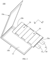
FIG. 1 is a schematic structural diagram of a secondary battery according to some embodiments of this application; -
FIG. 2 is an explosion schematic diagram of the secondary battery according to some embodiments of this application; -
FIG. 3 is a schematic structural diagram of a secondary battery according to some embodiments of this application; -
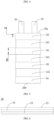
FIG. 4 is a schematic diagram of a winding structure of a jelly roll according to some embodiments of this application; -
FIG. 5 is a schematic diagram of installation of a jelly roll and adhesive members according to some embodiments of this application; -
FIG. 6 is a schematic structural diagram of an adhesive member according to some embodiments of this application; -
FIG. 7 is a schematic structural diagram of a jelly roll according to some embodiments of this application; and -
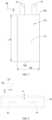
FIG. 8 is a top view of a secondary battery according to some embodiments of this application. -
- 100. Secondary battery;
- 10. Packaging bag; 10a. First bag body; 10b. Second bag body; 11. Accommodation cavity; 12. Pouch cavity; 13. Top sealing; 14. Side sealing;
- 20. Jelly roll; 20a. First end portion; 20b. Second end portion; 21. First electrode plate; 22. Second electrode plate; 23. Separator; 24. First outer surface; 241. Uncovered region;
- 30. Adhesive member; 31. Substrate layer; 32. First adhesive layer; 33. Second adhesive layer;
- 40. Tab; 41. First tab; 42. Second tab;
- X. First direction; Y Second direction; Z. Third direction; M. Winding direction.
- Embodiments of the technical solution of this application are described in detail below with reference to the accompanying drawings. The following embodiments are only used to more clearly illustrate the technical solution of this application, and therefore, are merely examples and cannot be used to limit the protection scope of this application.
- It is hereby noted that when an element is referred to as being "fixed to" or "disposed on" another element, the element can be directly on the another element, or there may be one or more intervening elements present therebetween. When an element is referred to as being "connected to" another element, the element can be directly connected to the another element, or there may be one or more intervening elements present therebetween.
- In the description of the embodiments of this application, the technical terms "first", "second", and the like are merely used to distinguish between different objects, and shall not be construed as any indication or implication of relative importance or any implicit indication of the quantity, particular sequence or primary-secondary relationship of the technical features indicated. In the description of the embodiments of this application, "a plurality of" means two or more unless otherwise expressly and specifically defined.
- In the description of the embodiments of this application, the term "and/or" describes only an association relationship between associated objects and represents that three relationships may exist. For example, A and/or B may represent the following three cases: Only A exists, both A and B exist, and only B exists. In addition, the character "/" in this specification generally indicates an "or" relationship between the associated objects.
- Reference to "embodiments" in this specification means that particular features, structures, or characteristics described with reference to the embodiments may be included in at least one embodiment of this application. Occurrence of the phrase in various places in this specification does not necessarily refer to the same embodiment, nor is an independent or alternative embodiment that is mutually exclusive with other embodiments. In addition, the technical features involved in different embodiments of this application described below can be combined with each other as long as the technical features do not conflict with each other.
- According to a first aspect, an embodiment of this application proposes a
secondary battery 100. Referring toFIG. 1 , thesecondary battery 100 includes apackaging bag 10, ajelly roll 20, and aadhesive member 30. Thejelly roll 20 is accommodated in thepackaging bag 10, theadhesive member 30 is provided on an outer surface of thejelly roll 20 in a sleeving manner, and theadhesive member 30 is adhered between thejelly roll 20 and thepackaging bag 10. - For the
above packaging bag 10, referring toFIG. 1 to FIG. 3 , anaccommodation cavity 11 is enclosed by thepackaging bag 10, and theaccommodation cavity 11 can accommodate theabove jelly roll 20 and an electrolyte (not marked in the figure). Thepackaging bag 10 may be a multi-layer compositefilm packaging bag 10 including a metal layer. Thepackaging bag 10 may be an aluminum-plastic film packaging bag including a PP (polypropylene) layer and an aluminum layer. For example, thepackaging bag 10 includes afirst bag body 10a and asecond bag body 10b. Thefirst bag body 10a and/or thesecond bag body 10b are/is punched with apouch cavity 12. Thejelly roll 20 may be disposed in thepouch cavity 12, and then edges of thefirst bag body 10a and thesecond bag body 10b are hot-pressed and sealed, so that a PP layer of thefirst bag body 10a and a PP layer of thesecond bag body 10b are adhered, and therefore, thecomplete packaging bag 10 is formed, theaccommodation cavity 11 is formed in thepouch cavity 12, and the hot-pressed and sealed parts form atop seal edge 13 and aside seal edge 14 of thepackaging bag 10. - For the
above jelly roll 20, referring toFIG. 1 andFIG. 4 , thejelly roll 20 is accommodated in theaccommodation cavity 11 of thepackaging bag 10. Thejelly roll 20 includes afirst electrode plate 21, asecond electrode plate 22, and aseparator 23. Thefirst electrode plate 21, thesecond electrode plate 22, and theseparator 23 are stacked and wound to form thejelly roll 20. Theseparator 23 is disposed between thefirst electrode plate 21 and thesecond electrode plate 22, to separate the two electrode plates. Thefirst electrode plate 21 and thesecond electrode plate 22 have opposite polarities, one of which is a cathode electrode plate and the other is an anode electrode plate. Theseparator 23 can be adhered between thefirst electrode plate 21 and thesecond electrode plate 22, which can reduce shrinkage of theseparator 23, thereby reducing a risk of a short circuit caused by contact between thefirst electrode plate 21 and thesecond electrode plate 22; and improving overall bonding strength of thejelly roll 20, to alleviate expansion of thejelly roll 20. - Referring to
FIG. 2 ,FIG. 3 , andFIG. 4 , thejelly roll 20 is electrically connected to atab 40. Thetab 40 includes afirst tab 41 and asecond tab 42. Thefirst tab 41 is electrically connected to thefirst electrode plate 21. Thesecond tab 42 is electrically connected to thesecond electrode plate 22. For example, further referring toFIG. 5 , along a first direction X, thejelly roll 20 includes afirst end portion 20a and asecond end portion 20b that are disposed opposite to each other, and thefirst tab 41 and thesecond tab 42 both protrude from thefirst end portion 20a of thejelly roll 20. After thejelly roll 20 is accommodated in thepackaging bag 10, thefirst end portion 20a is close to thetop seal edge 13 of thepackaging bag 10, and both thefirst tab 41 and thesecond tab 42 can extend from thetop seal edge 13. Thetab 40 is connected to the cathode and anode electrode plates of thejelly roll 20, so as to transfer positive and negative charges of thejelly roll 20 to an external circuit, so that thesecondary battery 100 can charge and discharge. The first direction X is a winding axis direction of thejelly roll 20, which may also be considered as a width direction of thefirst electrode plate 21 and/or a width direction of thesecond electrode plate 22, or a length direction of thejelly roll 20. - For the above
adhesive members 30, referring toFIG. 1 andFIG. 4 , along a winding direction M of thejelly roll 20, theadhesive member 30 encircles thejelly roll 20 and are provided on the outer surface of thejelly roll 20 in a sleeving manner, so as to tighten the electrode plates and theseparators 23 at layers of thejelly roll 20, so that adhesion of the layers of thejelly roll 20 is stable and gas generated by thejelly roll 20 can be reduced, which can effectively alleviate expansion of thejelly roll 20, and reduce breakage of thepackaging bag 10. Optionally, theadhesive member 30 is adhered to the outer surface of thejelly roll 20, which can further improve bonding strength between the electrode plates and theseparator 23 at the layers. Preferably, theadhesive member 30 is adhered between thejelly roll 20 and thepackaging bag 10, which can reduce movement of thejelly roll 20 in thepackaging bag 10, and reduce impact of thejelly roll 20 on thepackaging bag 10. - In some embodiments, the
adhesive member 30 includes hot melt adhesive or pressure-sensitive adhesive. The hot melt adhesive needs to be heated during use. Hot melting and solification of the hot melt adhesive can be achieved during a formation stage of thesecondary battery 100. Liquid hot melt adhesive is viscous and can firmly adhere thejelly roll 20 to thepackaging bag 10. After the formation stage finished, the hot melt adhesive quickly cools and solidifies, which can ensure bonding strength between thejelly roll 20 and thepackaging bag 10. A characteristic of the pressure-sensitive adhesive is that the pressure-sensitive adhesive can perform adhesion when slight pressure is applied without a need for additional heating, solvent, or water. For example, after thejelly roll 20 is accommodated in thepackaging bag 10, the adhesion of thejelly roll 20 to thepackaging bag 10 can be implemented by slightly pressing an outer surface of thepackaging bag 10 towards thejelly roll 20. Such an operation is simple and convenient, and can ensure the bonding strength between thejelly roll 20 and thepackaging bag 10. - In some other embodiments, referring to
FIG. 6 , theadhesive member 30 includes asubstrate layer 31, and two opposite surfaces of thesubstrate layer 31 along a thickness direction of the substrate layer are respectively provided with a firstadhesive layer 32 and a secondadhesive layer 33. - The
substrate layer 31 is used as a supporting structure of the firstadhesive layer 32 and the secondadhesive layer 33, and has high strength. Thesubstrate layer 31 can be prepared by using a material such as polyethylene, polypropylene, polyester, polyvinyl chloride, or polyimide. The firstadhesive layer 32 is adhered to thejelly roll 20, and the firstadhesive layer 32 includes the pressure-sensitive adhesive. When preparation of thejelly roll 20 is completed, theadhesive member 30 is arranged on the outer surface of thejelly roll 20 in a sleeving manner, and the firstadhesive layer 32 faces thejelly roll 20. The firstadhesive layer 32 can be adhered to thejelly roll 20 by applying pressure towards thejelly roll 20 on theadhesive member 30. The secondadhesive layer 33 is adhered to thepackaging bag 10, and the secondadhesive layer 33 includes the hot-melt adhesive or the pressure-sensitive adhesive. When the hot-melt adhesive is adopted, the hot-melt adhesive can be adhered to thepackaging bag 10 by heat generated in the formation stage of thesecondary battery 100. When the pressure-sensitive adhesive is adopted, thejelly roll 20 can be first placed in thepackaging bag 10, and adhesion between the pressure-sensitive adhesive and thepackaging bag 10 can be implemented by slightly pressing thepackaging bag 10 externally. - Optionally, the
adhesive member 30 includes an adhesive resin, a tackifying resin, and a curing agent. - The adhesive resin is a type of chemical substances commonly used in preparation of an adhesive agent, has adhesion and agglutination, and can be used to bond various materials. The adhesive resin includes one or more of a polyethylene-chlorotrifluoroethylene resin, a polypropylene resin, a modified polypropylene resin, an acrylic modified polyolefin resin, a polyethylene chlorotrifluoroethylene resin, an ethylene-vinyl acetate copolymer, an ethylene propylene copolymer, ethylene propylene diene monomer, ethylene propylene rubber, an ethylene propylene styrene acrylonitrile copolymer, an ethylene propylene terpolymer, isobutylene isoprene rubber, isoprene rubber, a maleic anhydride modified polyolefin resin, a modified polyphenylene ether resin, a modified polystyrene resin, a styrene-methylmethacrylate resin, acrylonitrile-butadiene rubber, polybutadiene rubber, a polybutadiene acrylonitrile resin, polypropylene butadiene rubber, a polybutadiene styrene resin, a styrene vinylbutadiene styrene copolymer, a styrene isoprene styrene block copolymer, a styrene butadiene styrene block copolymer, styrene-butadiene rubber, a styrene maleic anhydride copolymer, a syndiotactic polystyrene, an ethylene acrylic acid copolymer, a polytrifluorochloroethylene resin, a polyvinylidene fluoride resin, an ethylene-tetrafluoroethylene copolymer, an ethylene-chlorotrifluoroethylene copolymer, a polyvinyl fluoride resin, a polystyrene acrylonitrile resin, a polyorganosiloxane resin, a furfural phenol resin, a furfural acetone resin, a furfuryl alcohol resin, a phenolic resin, an epoxy resin, or an unsaturated polyester resin.
- The tackifying resin is a type of special adhesive resins that can increase adhesion performance. When the tackifying resin is added to the
adhesive member 30, viscosity and adhesion of theadhesive member 30 can be improved. The tackifying resin can improve fluidity, adhesion, and shear resistance performance of theadhesive member 30 to stably adhere thejelly roll 20 to thepackaging bag 10. The tackifying resin includes one or more of a rosin resin, a terpene resin, a petroleum resin, a phenolic resin, or an epoxy resin. - The curing agent is a type of chemical substances used to promote curing or hardening of the
adhesive member 30. The curing agent chemically reacts with main ingredients of the adhesive resin and/or the tackifying resin, thereby converting the adhesive agent from a liquid or semi-solid state to a solid state, to enhance adhesion performance and durability. For example, when theadhesive member 30 uses the hot melt adhesive, adding the curing agent to the hot melt adhesive can solidify and harden the hot melt adhesive faster and improve adhesion strength. The curing agent includes one or more of epoxidized m-phenylenediamine, a 4,4'-diaminodiphenylmethane epoxy resin, p-Aminophenol triglycidyl ether, hexamethylene diisocyanate, or methylene diphenyl diisocyanate, and the chemical substances can react chemically with molecules of a substrate in the hot-melt adhesive to form a cross-linking structure, so as to cause the molecules of the hot-melt adhesive to be staggered with each other, and increase firmness and stability of the adhesion. In addition, adding the curing agent can also improve fluidity of the hot melt adhesive, making it easier to coat the hot melt adhesive. - A molecular weight of the above adhesive resin can be selected from 10,000 to 10,000,000. A ratio of the adhesive resin, the tackifying resin, and the curing agent is (50% to 90%):(10% to 50%):(0.1% to 5%).
- In embodiments of this application, the
secondary battery 100 may be a long and narrow battery. For example, referring toFIG. 5 andFIG. 7 , a length of thejelly roll 20 is L mm (not including thefirst tab 41 and the second tab 42) along the first direction X, and a width of thejelly roll 20 is W1 mm along a second direction Y, where 2 ≤ L / W1 <_ 6, so that the secondary battery is suitable for electronic products such as smart watches, smart glasses, and Bluetooth headsets. The second direction Y is a width direction of thejelly roll 20, and the second direction Y is perpendicular to the first direction X. Theadhesive members 30 are arranged on and adhered to thesecondary battery 100 in a sleeving manner, so that adhesion of the electrode plates and theseparator 23 of thejelly roll 20 can be stable, and the gas generated by thejelly roll 20 can be reduced, which can alleviate the expansion of thejelly roll 20, thereby reducing the breakage of thepackaging bag 10. This solution is especially suitable for a narrow and longsecondary battery 100. For example, 50 ≤ L ≤ 200, and 20 <_ W1 ≤ 100; and preferably, 50 ≤ L ≤ 150, and 25 ≤ W1 ≤ 100. - Referring to
FIG. 1 andFIG. 5 , there are a plurality of theadhesive members 30, the plurality of theadhesive members 30 are provided on the outer surface of thejelly roll 20 in a sleeving manner, and the plurality of theadhesive members 30 are provided at intervals along the first direction X. Arrangement of the plurality of theadhesive members 30 can disperse stress on thejelly roll 20. For example, stress on both sides along the width direction of thejelly roll 20 is dispersed to the plurality of theadhesive members 30, which can reduce a local stress impact, alleviate the expansion of thejelly roll 20, and reduce the breakage of thepackaging bag 10. Optionally, the plurality of theadhesive members 30 are distributed along the first direction X at equal intervals on the outer surface of thejelly roll 20, to evenly disperse the stress on thejelly roll 20. - In some embodiments, a quantity of the
adhesive member 30 is N, N >_

jelly roll 20 is 3, at least four of theadhesive members 30 can be adopted. For example, the four of theadhesive members 30 are all provided on thejelly roll 20 in a sleeving manner, and the four of theadhesive members 30 are sequentially provided at intervals along the first direction X. Alternatively, L / W1 = 3.5, so X = 4.5,
adhesive members 30 may be used to adhere to thejelly roll 20, so as to ensure that theadhesive members 30 are stably arranged on thejelly roll 20 in a sleeving manner. The quantity of theadhesive member 30 is limited based on the length-to-width ratio of thejelly roll 20, and
jelly roll 20 indicates more of theadhesive members 30 required for adhesion, so as to disperse stress on parts of theadhesive members 30, and reduce stress concentration. - Referring to
FIG. 4 andFIG. 7 , in some embodiments, thejelly roll 20 has a firstouter surface 24 arranged along the winding direction M, and an area of the firstouter surface 24 is S1 mm2. A coverage area of asingle adhesive member 30 on the firstouter surface 24 is S2 mm2, and 10% ≤ S2 / S1 <_ 20%. Thesingle adhesive member 30 has a sufficient adhesive area with the firstouter surface 24, which can reduce stress concentration, and reduce tightening damage to thejelly roll 20, and the adhesive member can be stably arranged in a sleeving manner and adhered. A coverage area of all theadhesive members 30 on the firstouter surface 24 is S3 mm2, and 40% ≤ S3 / S1 <_ 80%, which can reduce tightening damage of theadhesive members 30 to thejelly roll 20. In addition, theadhesive members 30 also adhere to thepackaging bag 10. In the above adhesion area, when thejelly roll 20 and thepackaging bag 10 have a relative movement tendency or have relative movement, tearing of theadhesive members 30 can be reduced, to enhance bonding strength between thejelly roll 20 and thepackaging bag 10. - Because the
adhesive member 30 is arranged on the firstouter surface 24 of thejelly roll 20 in a sleeving manner, and a circumference of theadhesive member 30 is substantially consistent with a circumference of the firstouter surface 24 along the winding direction M, the coverage area of theadhesive member 30 on the firstouter surface 24 is related to a width of theadhesive member 30 along the first direction X. In the embodiments of this application, the width of theadhesive member 30 along the first direction X is W2 mm, where 2 ≤ W2 <_ 20, which can reduce stress concentration and reduce tightening damage to thejelly roll 20. Optionally, referring toFIG. 8 , along a third direction Z, a thickness of theadhesive member 30 is T1 µm, and 5 <_ T1 ≤ 80, which can ensure bonding strength of theadhesive member 30, reduce a space occupied by theadhesive member 30, and ensure energy density of thesecondary battery 100. The third direction Z is perpendicular to the first direction X, and the third direction Z is perpendicular to the winding direction M of thejelly roll 20. Because the winding direction M is actually formed by a combination of countless directions, and the winding direction M is perpendicular to and corresponds to the third direction Z, the third direction Z also includes countless directions (only one third direction Z is shown inFIG. 8 ), and the third direction Z may be considered as a direction from the adhesive member to thejelly roll 20. - Optionally, referring to
FIG. 5 , the firstouter surface 24 of thejelly roll 20 has a plurality of uncoveredregions 241. The uncoveredregions 241 refer to regions of the outer surface of thejelly roll 20 that are not covered by theadhesive members 30. A quantity of the uncoveredregions 241 is M, and M = N - 1. In this case,adhesive members 30 are arranged on both locations of the firstouter surface 24 that are close to thefirst end portion 20a and thesecond end portion 20b in a sleeving manner. Both thefirst end portion 20a and thesecond end portion 20b are at edge locations of thejelly roll 20, and bonding strength that is between the electrode plates and theseparator 23 and that is near the two end portions is weak. Theadhesive members 30 are arranged on both the locations close to thefirst end portion 20a and thesecond end portion 20b in a sleeving manner, which can further improve the bonding strength of thejelly roll 20 and effectively disperse the stress. - In the embodiments of this application, the
adhesive member 30 encircles thejelly roll 20 and are arranged on the outer surface of thejelly roll 20 in a sleeving manner, so as to tighten the electrode plates and theseparator 23 at the layers of thejelly roll 20, so that the adhesion of the layers of thejelly roll 20 is stable and the gas generated by thejelly roll 20 can be reduced, which can effectively alleviate the expansion of thejelly roll 20, and thus reduce the breakage of thepackaging bag 10. In addition, theadhesive members 30 can disperse stress of thejelly roll 20, reduce the local stress impact, alleviate the expansion of thejelly roll 20, and reduce the breakage of thepackaging bag 10. Moreover, thejelly roll 20 and thepackaging bag 10 are adhered via theadhesive member 30, which can reduce movement of thejelly roll 20 in thepackaging bag 10, thereby reducing the impact of thejelly roll 20 on thepackaging bag 10, further reducing the breakage of thepackaging bag 10, and improving high temperature resistance performance of thesecondary battery 100. - In the embodiments of this application, a lithium-ion battery is used as an example, and a high-temperature test is performed on the lithium-ion battery.
- Using graphite as a negative active material, mixing the negative active material graphite, a binder styrene-butadiene rubber (SBR), and a thickening agent sodium carboxymethyl cellulose (CMC) in a weight ratio of 96:2:2, and adding deionized water as a solvent, to prepare a slurry with a solid content of 70 wt% and stir evenly. Evenly coating the slurry on one surface of a copper foil with a thickness of 10 µm, and drying to obtain a negative electrode plate coated with a negative active layer on one surface. Repeating the above steps on the other surface of the copper foil, to obtain a negative electrode plate coated with negative active layers on both surfaces.
- Mixing a positive active material lithium cobalt oxide (LiCoO2), conductive carbon black (Super P), and polyvinylidene difluoride (PVDF) in a weight ratio of 97.5:1.0:1.5, and adding N-methyl-pyrrolidone (NMP) as a solvent, to prepare a slurry with a solid content of 75 wt% and stir evenly. Evenly coating the slurry on one surface of an aluminum foil with a thickness of 12 µm, and drying to obtain a positive electrode plate coated with a positive active layer on one surface. Repeating the above steps on the other surface of the aluminum foil, to obtain a positive electrode plate coated with positive active layers on both surfaces.
- In the atmosphere of dry argon gas, first mixing ethylene carbonate (EC), ethyl methyl carbonate (EMC), and diethyl carbonate (DEC) in a mass ratio of EC:EMC:DEC = 30:50:20 to obtain a basic organic solvent, and then adding lithium salts lithium hexafluorophosphate (LiPF6) to the basic organic solvent to dissolve and mix evenly to obtain an electrolyte solution in which a mass concentration of LiPF6 is 12.5%.
- Using a polyethylene porous film as a substrate layer, and coating a ceramic layer containing alumina ceramics and a PVDF binder on one side surface of the substrate layer as a separator, where a mass percentage of the alumina ceramics in the ceramic layer is 95%.
- Mixing a polypropylene resin (an adhesive resin), an epoxy resin (a tackifying resin), and m-Phenylenebis(diglycidylaminomethane) (a curing agent) in a ratio of 70%:25%:5% to prepare an adhesive member with hot melt adhesive.
- Stacking and winding the above-mentioned positive electrode plate, separator, and negative electrode plate. Using a 12 mm × 1 mm nickel sheet and aluminum sheet as tabs. Welding the aluminum-sheet tab to the positive electrode plate (aluminum foil of the positive electrode plate), and welding the nickel-sheet tab to the negative electrode plate (copper foil of the negative electrode plate), to form a jelly roll.
- (7) Jelly roll assembly: Arranging and adhering the above-mentioned adhesive members to an outer surface of a jelly roll in a sleeving manner, where near two ends along a length direction of the jelly roll, the
adhesive members 30 sleeve the jell roll . Placing, in a modular fixture, an aluminum-plastic film molded through pouch forming, with a pouch surface facing upward, and placing the jelly roll in a pouch. Applying an external force for compaction, so that theadhesive member 30 and the aluminum-plastic film are preliminarily adhered. Covering the jelly roll with another aluminum-plastic film molded through pouch forming, with a pouch surface facing downward, and performing hot sealing on surroundings of the two aluminum-plastic films by hot pressing, to obtain the assembled jelly roll. A length L of the jelly roll = 50 mm, and a width W1 = 25 mm; and L / W1 = 2. A quantity of the adhesive members is 3, the three adhesive members are arranged in a sleeving manner at equal intervals in the length direction of the jelly roll, and a width of the adhesive member in the length direction of the jelly roll is 10 mm. - (8) Liquid injection and packaging: Injecting an electrolyte solution into the assembled jelly roll, performing vacuum packaging, standing, and hot-pressing formation, to make adhesive members be stably adhered between the jelly roll and a packaging bag, and performing shaping and other processes to prepare a lithium-ion battery.
- Different from the embodiment 1, a length L of a jelly roll = 100 mm, and a width W1 = 25 mm; and L / W1 = 4.
- Different from the embodiment 1, a length L of a jelly roll = 150 mm, and a width W1 = 25 mm; and L / W1 = 6.
- Different from the embodiment 1, a length L of a jelly roll = 100 mm, and a width W1 = 35 mm; and L / W1 = 2.87.
- Different from the embodiment 1, a length L of a jelly roll = 200 mm, and a width W1 = 35 mm; and L / W1 = 5.71.
- Different from the embodiment 1, a length L of a jelly roll = 100 mm, and a width W1 = 50 mm; and L/W1 = 2.
- Different from the embodiment 1, a length L of a jelly roll = 200 mm, and a width W1 = 50 mm; and L / W1 = 4.
- Different from the embodiment 1, a length L of a jelly roll = 200 mm, and a width W1 = 100 mm; and L / W1 = 2.
- Different from the embodiment 1, no adhesive member is provided.
- Different from the embodiment 1, a length L of a jelly roll = 200 mm, and a width W1 = 25 mm; and L / W1 = 8.
- Different from the embodiment 1, a length L of a jelly roll = 200 mm, and a width W1 = 150 mm; and L / W1 = 1.33.
-
- 1). A lithium-ion battery stands at 25 °C for 5 minutes.
- 2). Charge the lithium-ion battery at 0.5C DC (Direct Current) to 3.0V.
- 3). The lithium-ion battery stands for another 5 minutes.
- 4). Convert the lithium-ion battery at 0.5C CC (Constant Current) 4.5V CV (Constant Voltage) to 0.05C.
- 5). After the lithium-ion battery stands for 5 minutes, transfer the lithium-ion battery to a heating furnace, raise a temperature at 5 °C/min to 100 degC, and keep the temperature constant for 5 h.
- 6). Turn off the heating, cool naturally to a room temperature, and check whether the lithium-ion battery has breakage and liquid leakage.
- Test results are shown in Table 1 below.
Table 1 L (mm) W1 (mm) L/ W1 With adhesive members or not Breakage and liquid leakage Embodiment 1 50 25 2 Yes 0/10 Embodiment 2 100 25 4 Yes 0/10 Embodiment 3 150 25 6 Yes 0/10 Embodiment 4 100 35 2.87 Yes 0/10 Embodiment 5 200 35 5.71 Yes 0/10 Embodiment 6 100 50 2 Yes 0/10 Embodiment 7 200 50 4 Yes 0/10 Embodiment 8 200 100 2 Yes 0/10 Comparative Embodiment 1 50 25 2 None 10/10 Comparative Embodiment 2 200 25 8 Yes 7/10 Comparative Embodiment 3 200 150 1.33 Yes 6/10 - According to the above Table 1, with reference to Embodiments 1 to 8 and Comparative embodiment 1, it can be learned that when the adhesive members are arranged on the outer surface of the jelly roll in a sleeving manner, the breakage and liquid leakage of the lithium-ion battery can be effectively reduced. In Comparative embodiment 2, the length-to-width ratio L / W1 of the jelly roll is large, more adhesive members are needed for adhesion, and a manufacturing process is increased, which is not conducive to improving production efficiency of the lithium-ion battery. In addition, because the length-to-width ratio of the jelly roll is large, a bonding force between layers of the jelly roll is weakened, and the jelly roll is more prone to expand, which may lead to breakage of a side seal edge of the packaging bag. In Comparative embodiment 3, the length-to-width ratio L / W1 of the jelly roll is small, and stress concentration may also occur on a top end of the jelly roll (along an extension direction of a tab). The adhesive members can limit expansion of side edges (both sides along a width direction of the jelly roll) of the jelly roll, but cannot limit the top end of the jelly roll, which may cause breakage of top sealing of the packaging bag. With reference to Embodiments 1 to 8 and Comparative embodiments 2 and 3, when 2 ≤ L / W1 ≤ 6, the breakage and liquid leakage of the packaging bag can be effectively reduced. In addition, with reference to Embodiments 1 to 8, optionally, 50 <_ L ≤ 200, and 20 ≤ W1 ≤ 100; and preferably, 50 ≤ L ≤ 150, and 25 ≤ W1 ≤ 100. In this range, the breakage and liquid leakage of the packaging bag are effectively reduced.
- In the embodiments of this application, the lithium-ion battery is used as an example, and the high-temperature test is performed on the lithium-ion battery again.
- Different from Embodiment 1, a quantity of adhesive members is 1.
- Different from Embodiment 1, a quantity of adhesive members is 2.
- Different from Embodiment 1, a quantity of adhesive members is 4.
- Different from Embodiment 1, a quantity of adhesive members is 5.
- Different from Embodiment 1, adhesive members are not arranged on locations close to two ends along a length direction of a jelly roll in a sleeving manner.
- Different from Embodiment 1, a width W2 of an adhesive member = 5 mm, a quantity of adhesive members is 1, and one adhesive member is adhered in a middle location of a jelly roll along a length direction of the jelly roll.
- Different from Embodiment 1, a width W2 of an adhesive member = 5 mm, and a quantity of adhesive members is 2.
- Different from Embodiment 1, a width W2 of an adhesive member = 5 mm, and a quantity of adhesive members is 3.
- Different from Embodiment 1, a width W2 of an adhesive member = 5 mm, a quantity of adhesive members is 3, and adhesive members are not arranged on locations close to two ends along a length direction of a jelly roll in a sleeving manner.
- Different from Embodiment 1, a width W2 of an adhesive member = 5 mm, and a quantity of adhesive members is 4.
- Different from Embodiment 1, a width W2 of an adhesive member = 5 mm, and a quantity of adhesive members is 5.
- Different from Embodiment 1, a width W2 of an adhesive member = 5 mm, and a quantity of adhesive members is 6.
- Test results are shown in Table 2 below.
Table 2 L(mm) W1(mm) W2(mm) N M Breakage and liquid leakage Embodimen t 1 50 25 10 3 2 0/10 Embodimen t 9 50 25 10 1 2 1/10 Embodimen t 1050 25 10 2 1 1/10 Embodimen t 1150 25 10 4 3 1/10 Embodimen t 1250 25 10 5 0 1/10 Embodimen t 1350 25 10 3 4 2/10 Embodimen t 1450 25 5 1 2 1/10 Embodimen t 15 50 25 5 2 1 1/10 Embodimen t 16 50 25 5 3 2 0/10 Embodimen t 17 50 25 5 3 4 3/10 Embodimen t 18 50 25 5 4 3 1/10 Embodimen t 19 50 25 5 5 4 1/10 Embodimen t 2050 25 5 6 5 1/10 - According to the above Table 2, with reference to Embodiment 9, Embodiment 18, and the above Embodiment 1, it can be learned that when the adhesive members are not arranged on the locations close to the two ends along the length direction of the jelly roll in a sleeving manner, slight breakage and liquid leakage occur. This is because the stress concentration occurs at the two ends along the length direction of the jelly roll, and a separator shrinks, the jelly roll expands and generates gas, resulting in the breakage and the liquid leakage of the packaging bag. Therefore, in the embodiments of this application, preferably, the adhesive members are arranged on the locations close to the two ends along the length direction of the jelly roll in a sleeving manner, that is, a quantity M of uncovered regions = N - 1.
-
Embodiments 
Embodiments Embodiments 


- In the embodiments of this application, a lithium-ion battery is used as an example, and a high-temperature test is performed on the lithium-ion battery.
- Different from Embodiment 1, a quantity of adhesive members is 1, and one adhesive member is adhered in a middle location of a jelly roll along a length direction of the jelly roll.
- Different from Embodiment 1, a quantity of adhesive members is 2.
- Different from Embodiment 1, a quantity of adhesive members is 4.
- Different from Embodiment 1, a quantity of adhesive members is 5.
- Different from Embodiment 1, a width W2 of an adhesive member = 5 mm, a quantity of adhesive members is 1, and one adhesive member is adhered in a middle location of a jelly roll along a length direction of the jelly roll.
- Different from Embodiment 1, a width W2 of an adhesive member = 5 mm, and a quantity of adhesive members is 3.
- Different from Embodiment 1, a width W2 of an adhesive member = 5 mm, and a quantity of adhesive members is 5.
- Different from Embodiment 1, a width W2 of an adhesive member = 5 mm, and a quantity of adhesive members is 8.
- Different from Embodiment 1, a width W2 of an adhesive member = 5 mm, and a quantity of adhesive members is 10.
- Different from Embodiment 1, a width W2 of an adhesive member = 15 mm, and a quantity of adhesive members is 1.
- Different from Embodiment 1, a width W2 of an adhesive member = 15 mm, and a quantity of adhesive members is 2.
- Different from Embodiment 1, a width W2 of an adhesive member = 15 mm, and a quantity of adhesive members is 3.
- Different from Embodiment 1, a width W2 of an adhesive member = 2.5 mm, and a quantity of adhesive members is 10.
- Test results are shown in Table 3 below.
Table 3 L(mm) W2(mm) N S2/S1 S3/S1 Breakage and liquid leakage Embodiment 1 50 10 3 20% 60% 0/10 Embodiment 2150 10 1 20% 20% 1/10 Embodiment 2250 10 2 20% 40% 0/10 Embodiment 2350 10 4 20% 80% 0/10 Embodiment 2450 10 5 20% 100% 2/10 Embodiment 25 50 5 1 10% 10% 2/10 Embodiment 26 50 5 3 10% 30% 0/10 Embodiment 27 50 5 5 10% 50% 0/10 Embodiment 28 50 5 8 10% 80% 0/10 Embodiment 29 50 5 10 10% 100% 1/10 Embodiment 3050 15 1 30% 30% 2/10 Embodiment 3150 15 2 30% 60% 1/10 Embodiment 3250 15 3 30% 90% 1/10 Embodiment 3350 2.5 10 5% 50% 2/10 - In
Embodiment 33, a width of a single adhesive member is small. When such adhesive members are arranged on an outer surface of a jelly roll in a sleeving manner, stress dispersion by the adhesive members is not obvious, which may cause tightening cracks on the outer surface of the jelly roll and may cause local expansion of the jelly roll, resulting in the breakage and the liquid leakage of the packaging bag. InEmbodiment 24 and Embodiment 29, an outer surface of a jelly roll in a winding direction is completely covered, which not only affects energy density, but also is difficult for an electrolyte solution to penetrate the jelly roll, and cyclic lithium plating is prone to occur. With reference to theabove Embodiments 21 to 33, it can be learned that when 10% ≤ S2 / S1 ≤ 20%, and 40% ≤ S3 / S1 ≤ 80%, the breakage and the liquid leakage of the packaging bag can be effectively reduced. - According to a second aspect, an embodiment of this application further provides an electronic device, including the
secondary battery 100 in any embodiment of the first aspect. The electronic device in this embodiment of this application is not particularly limited, and can be any electronic device known in the prior art. For example, the electronic device includes, but is not limited to, Bluetooth headsets, a mobile phone, a tablet, a laptop, an electric toy, an electric tool, or the like. - Finally, it is hereby noted that the foregoing embodiments are merely intended to illustrate technical solutions of this application rather than to limit this application; under the thought of this application, technical features in the foregoing embodiments or different embodiments may also be combined, steps may be implemented in any orders, and there are many other changes in different aspects of this application as described above, which are not provided in detail for the sake of brevity; although this application is illustrated in detail with reference to the foregoing embodiments, a person of ordinary skill in the art understands that he may still make modifications to the technical solutions recited in the foregoing embodiments or make equivalent replacements to some of the technical features; however, these modifications or replacements do not make the essence of the corresponding technical solution depart from the scope of the technical solutions of the embodiments.
Claims (11)
- A secondary battery (100), comprising a packaging bag (10a) and a jelly roll (20) accommodated in the packaging bag (10a), characterized in that,along a first direction (X), a length of the jelly roll (20) is L mm;along a second direction (Y), a width of the jelly roll (20) is W1 mm;
 the secondary battery (100) further comprises at least one adhesive member (30), the at least one adhesive member (30) is provided on an outer surface of the jelly roll (20) in a sleeving manner along a winding direction (M) of the jelly roll (20);the at least one adhesive member (30) is adhered between the jelly roll (20) and the packaging bag (10a); andthe first direction (X) is a winding axis direction of the jelly roll (20), the second direction (Y) is a width direction of the jelly roll (20), the first direction (X) is perpendicular to the second direction (Y).
 - The secondary battery (100) according to claim 1, characterized in that, 50 < L ≤ 200, and 20 < W1 ≤ 100.
- The secondary battery (100) according to claim 2, characterized in that, 50 ≤ L ≤ 150, and 25 ≤ W1 ≤ 100.
- The secondary battery (100) according to any one of claims 1 to 3, characterized in that,the at least one adhesive member includes a plurality of adhesive members (30);the plurality of adhesive members (30) are all provided on the outer surface of the jelly roll (20) in a sleeving manner; andthe plurality of adhesive members (30) are provided at intervals along the first direction (X).
- The secondary battery (100) according to claim 4, characterized in that,the jelly roll (20) has a first outer surface (24) provided along the winding direction (M) of the jelly roll (20); andalong the first direction (X), the plurality of adhesive members (30) are provided at two ends of the first outer surface (24) in a sleeving manner.
- The secondary battery (100) according to claim 5, characterized in that,a quantity of adhesive members in the plurality of adhesive members (30) is N, X = (L/W1) + 1,
 the first outer surface (24) further has a plurality of uncovered regions (241), wherein the plurality of uncovered regions are not covered with the plurality of adhesive members (30); anda quantity of the uncovered regions in the plurality of uncovered regions (241) is M, M = N - 1.
 - The secondary battery (100) according to claim 4, characterized in that,the jelly roll (20) has a first outer surface (24) provided along the winding direction (M);an area of the first outer surface (24) is S1 mm2;a coverage area of each adhesive member (30) on the first outer surface (24) is S2 mm2, 10% ≤ S2/ S1 ≤ 20%; anda coverage area of all of the plurality of adhesive members (30) on the first outer surface (24) is S3 mm2, 40% ≤ S3/S1 ≤ 80%.
- The secondary battery (100) according to any one of claims 1 to 7, characterized in that,along the first direction (X), a width of each adhesive member (30) is W2 mm, 2 ≤ W2 ≤ 20;along a third direction (Z), a thickness of each adhesive member (30) is T1 µm, 5 ≤ T1 ≤ 80; andthe third direction (Z) is perpendicular to the winding direction (M) of the jelly roll (20), the third direction (Z) is perpendicular to the first direction (X).
- The secondary battery (100) according to any one of claims 1 to 8, characterized in that, each adhesive member (30) comprises a hot melt adhesive or a pressure-sensitive adhesive.
- The secondary battery (100) according to any one of claims 1 to 8, characterized in that,each adhesive member (30) comprises a substrate layer (31);two opposite surfaces of the substrate layer (31) along a thickness direction of the substrate layer (31) are respectively provided with a first adhesive layer (32) and a second adhesive layer (33);the first adhesive layer (32) is adhered to the jelly roll (20);the second adhesive layer (33) is adhered to the packaging bag (10a);the first adhesive layer (32) comprises a pressure-sensitive adhesive; andthe second adhesive layer (33) comprises a hot melt adhesive or the pressure-sensitive adhesive.
- An electronic device, characterized in that, the electronic device comprises the secondary battery (100) according to any one of claims 1 to 10.
Applications Claiming Priority (1)
| Application Number | Priority Date | Filing Date | Title |
|---|---|---|---|
| CN202311225745.3A CN117276764A (en) | 2023-09-21 | 2023-09-21 | Secondary batteries and electronic equipment |
Publications (1)
| Publication Number | Publication Date |
|---|---|
| EP4528866A1 true EP4528866A1 (en) | 2025-03-26 |
Family
ID=89207575
Family Applications (1)
| Application Number | Title | Priority Date | Filing Date |
|---|---|---|---|
| EP24201741.6A Pending EP4528866A1 (en) | 2023-09-21 | 2024-09-20 | Secondary battery and electronic device |
Country Status (2)
| Country | Link |
|---|---|
| EP (1) | EP4528866A1 (en) |
| CN (1) | CN117276764A (en) |
Families Citing this family (1)
| Publication number | Priority date | Publication date | Assignee | Title |
|---|---|---|---|---|
| CN117895094A (en) * | 2023-12-29 | 2024-04-16 | 宁德新能源科技有限公司 | Secondary battery and method for preparing the same |
Citations (4)
| Publication number | Priority date | Publication date | Assignee | Title |
|---|---|---|---|---|
| US20120115025A1 (en) * | 2010-10-04 | 2012-05-10 | Lg Chem, Ltd. | Seal tape and secondary battery using the same |
| US20150171383A1 (en) * | 2013-12-16 | 2015-06-18 | Samsung Sdi Co., Ltd. | Jelly roll tape for rechargeable battery and rechargeable battery having the same |
| US20170084899A1 (en) * | 2014-01-21 | 2017-03-23 | Microvast Power Systems Co., Ltd. | Battery Module |
| CN217903250U (en) * | 2022-08-17 | 2022-11-25 | 松山湖材料实验室 | Flexible battery pack and wearable electronic device |
-
2023
- 2023-09-21 CN CN202311225745.3A patent/CN117276764A/en active Pending
-
2024
- 2024-09-20 EP EP24201741.6A patent/EP4528866A1/en active Pending
Patent Citations (4)
| Publication number | Priority date | Publication date | Assignee | Title |
|---|---|---|---|---|
| US20120115025A1 (en) * | 2010-10-04 | 2012-05-10 | Lg Chem, Ltd. | Seal tape and secondary battery using the same |
| US20150171383A1 (en) * | 2013-12-16 | 2015-06-18 | Samsung Sdi Co., Ltd. | Jelly roll tape for rechargeable battery and rechargeable battery having the same |
| US20170084899A1 (en) * | 2014-01-21 | 2017-03-23 | Microvast Power Systems Co., Ltd. | Battery Module |
| CN217903250U (en) * | 2022-08-17 | 2022-11-25 | 松山湖材料实验室 | Flexible battery pack and wearable electronic device |
Also Published As
| Publication number | Publication date |
|---|---|
| CN117276764A (en) | 2023-12-22 |
Similar Documents
| Publication | Publication Date | Title |
|---|---|---|
| CN105958008B (en) | A kind of lithium ion battery anode composite piece, preparation method and lithium ion battery | |
| CN106328992B (en) | A lithium ion battery and a method for preparing the same | |
| JP5382130B2 (en) | Method for producing solid electrolyte battery | |
| KR102735726B1 (en) | Electrode sheet and method for manufacturing the same, secondary battery, battery module and battery pack | |
| EP4246701A1 (en) | Battery, electronic device, and mobile apparatus | |
| JP4649993B2 (en) | Lithium secondary battery and manufacturing method thereof | |
| KR19980064462A (en) | Lithium ion secondary battery | |
| EP4738495A1 (en) | Secondary battery and electronic device | |
| JP2000067920A (en) | Solid electrolyte battery | |
| EP3660940B1 (en) | Battery and device | |
| EP4625567A2 (en) | Secondary battery and electronic apparatus | |
| KR102759598B1 (en) | Batteries, battery modules, battery packs and power consumption devices | |
| CN108431992A (en) | Separator and battery containing same | |
| CN112805347A (en) | Insulating tapes, pole pieces and electrochemical devices | |
| WO2025139728A1 (en) | Secondary battery and preparation method therefor | |
| EP4704243A2 (en) | Secondary battery and electronic apparatus | |
| CN114204038B (en) | Current collectors and their applications | |
| CN221352801U (en) | Positive electrode sheet, battery and battery pack | |
| CN117276764A (en) | Secondary batteries and electronic equipment | |
| CN112750977B (en) | Electrode pole piece, electrode assembly, electrochemical device, electronic device and preparation method | |
| CN112713301A (en) | Energy storage device | |
| US20250300321A1 (en) | Battery | |
| EP4510255A1 (en) | Expanding adhesive tape for battery packaging, preparation method therefor, application thereof, secondary battery, and electrical apparatus | |
| KR102908653B1 (en) | A cathode for all-solid state battery for preventing a short and A manufacturing method of the same | |
| KR20260049676A (en) | Secondary batteries and electrical devices |
Legal Events
| Date | Code | Title | Description |
|---|---|---|---|
| PUAI | Public reference made under article 153(3) epc to a published international application that has entered the european phase |
Free format text: ORIGINAL CODE: 0009012 |
|
| STAA | Information on the status of an ep patent application or granted ep patent |
Free format text: STATUS: REQUEST FOR EXAMINATION WAS MADE |
|
| 17P | Request for examination filed |
Effective date: 20240920 |
|
| AK | Designated contracting states |
Kind code of ref document: A1 Designated state(s): AL AT BE BG CH CY CZ DE DK EE ES FI FR GB GR HR HU IE IS IT LI LT LU LV MC ME MK MT NL NO PL PT RO RS SE SI SK SM TR |