EP4528863A1 - Electrochemical device and electric device - Google Patents
Electrochemical device and electric device Download PDFInfo
- Publication number
- EP4528863A1 EP4528863A1 EP22947131.3A EP22947131A EP4528863A1 EP 4528863 A1 EP4528863 A1 EP 4528863A1 EP 22947131 A EP22947131 A EP 22947131A EP 4528863 A1 EP4528863 A1 EP 4528863A1
- Authority
- EP
- European Patent Office
- Prior art keywords
- housing
- electrode plate
- along
- separator
- projection
- Prior art date
- Legal status (The legal status is an assumption and is not a legal conclusion. Google has not performed a legal analysis and makes no representation as to the accuracy of the status listed.)
- Pending
Links
Images




Classifications
-
- H—ELECTRICITY
- H01—ELECTRIC ELEMENTS
- H01M—PROCESSES OR MEANS, e.g. BATTERIES, FOR THE DIRECT CONVERSION OF CHEMICAL ENERGY INTO ELECTRICAL ENERGY
- H01M50/00—Constructional details or processes of manufacture of the non-active parts of electrochemical cells other than fuel cells, e.g. hybrid cells
- H01M50/40—Separators; Membranes; Diaphragms; Spacing elements inside cells
- H01M50/46—Separators, membranes or diaphragms characterised by their combination with electrodes
-
- H—ELECTRICITY
- H01—ELECTRIC ELEMENTS
- H01M—PROCESSES OR MEANS, e.g. BATTERIES, FOR THE DIRECT CONVERSION OF CHEMICAL ENERGY INTO ELECTRICAL ENERGY
- H01M10/00—Secondary cells; Manufacture thereof
- H01M10/04—Construction or manufacture in general
- H01M10/0468—Compression means for stacks of electrodes and separators
-
- H—ELECTRICITY
- H01—ELECTRIC ELEMENTS
- H01M—PROCESSES OR MEANS, e.g. BATTERIES, FOR THE DIRECT CONVERSION OF CHEMICAL ENERGY INTO ELECTRICAL ENERGY
- H01M10/00—Secondary cells; Manufacture thereof
- H01M10/05—Accumulators with non-aqueous electrolyte
- H01M10/058—Construction or manufacture
- H01M10/0585—Construction or manufacture of accumulators having only flat construction elements, i.e. flat positive electrodes, flat negative electrodes and flat separators
-
- H—ELECTRICITY
- H01—ELECTRIC ELEMENTS
- H01M—PROCESSES OR MEANS, e.g. BATTERIES, FOR THE DIRECT CONVERSION OF CHEMICAL ENERGY INTO ELECTRICAL ENERGY
- H01M50/00—Constructional details or processes of manufacture of the non-active parts of electrochemical cells other than fuel cells, e.g. hybrid cells
- H01M50/10—Primary casings; Jackets or wrappings
- H01M50/102—Primary casings; Jackets or wrappings characterised by their shape or physical structure
- H01M50/103—Primary casings; Jackets or wrappings characterised by their shape or physical structure prismatic or rectangular
-
- H—ELECTRICITY
- H01—ELECTRIC ELEMENTS
- H01M—PROCESSES OR MEANS, e.g. BATTERIES, FOR THE DIRECT CONVERSION OF CHEMICAL ENERGY INTO ELECTRICAL ENERGY
- H01M50/00—Constructional details or processes of manufacture of the non-active parts of electrochemical cells other than fuel cells, e.g. hybrid cells
- H01M50/10—Primary casings; Jackets or wrappings
- H01M50/102—Primary casings; Jackets or wrappings characterised by their shape or physical structure
- H01M50/105—Pouches or flexible bags
-
- H—ELECTRICITY
- H01—ELECTRIC ELEMENTS
- H01M—PROCESSES OR MEANS, e.g. BATTERIES, FOR THE DIRECT CONVERSION OF CHEMICAL ENERGY INTO ELECTRICAL ENERGY
- H01M50/00—Constructional details or processes of manufacture of the non-active parts of electrochemical cells other than fuel cells, e.g. hybrid cells
- H01M50/10—Primary casings; Jackets or wrappings
- H01M50/172—Arrangements of electric connectors penetrating the casing
- H01M50/174—Arrangements of electric connectors penetrating the casing adapted for the shape of the cells
- H01M50/176—Arrangements of electric connectors penetrating the casing adapted for the shape of the cells for prismatic or rectangular cells
-
- H—ELECTRICITY
- H01—ELECTRIC ELEMENTS
- H01M—PROCESSES OR MEANS, e.g. BATTERIES, FOR THE DIRECT CONVERSION OF CHEMICAL ENERGY INTO ELECTRICAL ENERGY
- H01M50/00—Constructional details or processes of manufacture of the non-active parts of electrochemical cells other than fuel cells, e.g. hybrid cells
- H01M50/40—Separators; Membranes; Diaphragms; Spacing elements inside cells
- H01M50/403—Manufacturing processes of separators, membranes or diaphragms
- H01M50/406—Moulding; Embossing; Cutting
-
- H—ELECTRICITY
- H01—ELECTRIC ELEMENTS
- H01M—PROCESSES OR MEANS, e.g. BATTERIES, FOR THE DIRECT CONVERSION OF CHEMICAL ENERGY INTO ELECTRICAL ENERGY
- H01M50/00—Constructional details or processes of manufacture of the non-active parts of electrochemical cells other than fuel cells, e.g. hybrid cells
- H01M50/40—Separators; Membranes; Diaphragms; Spacing elements inside cells
- H01M50/463—Separators, membranes or diaphragms characterised by their shape
-
- H—ELECTRICITY
- H01—ELECTRIC ELEMENTS
- H01M—PROCESSES OR MEANS, e.g. BATTERIES, FOR THE DIRECT CONVERSION OF CHEMICAL ENERGY INTO ELECTRICAL ENERGY
- H01M50/00—Constructional details or processes of manufacture of the non-active parts of electrochemical cells other than fuel cells, e.g. hybrid cells
- H01M50/40—Separators; Membranes; Diaphragms; Spacing elements inside cells
- H01M50/471—Spacing elements inside cells other than separators, membranes or diaphragms; Manufacturing processes thereof
-
- H—ELECTRICITY
- H01—ELECTRIC ELEMENTS
- H01M—PROCESSES OR MEANS, e.g. BATTERIES, FOR THE DIRECT CONVERSION OF CHEMICAL ENERGY INTO ELECTRICAL ENERGY
- H01M50/00—Constructional details or processes of manufacture of the non-active parts of electrochemical cells other than fuel cells, e.g. hybrid cells
- H01M50/50—Current conducting connections for cells or batteries
- H01M50/543—Terminals
- H01M50/547—Terminals characterised by the disposition of the terminals on the cells
- H01M50/55—Terminals characterised by the disposition of the terminals on the cells on the same side of the cell
-
- H—ELECTRICITY
- H01—ELECTRIC ELEMENTS
- H01M—PROCESSES OR MEANS, e.g. BATTERIES, FOR THE DIRECT CONVERSION OF CHEMICAL ENERGY INTO ELECTRICAL ENERGY
- H01M50/00—Constructional details or processes of manufacture of the non-active parts of electrochemical cells other than fuel cells, e.g. hybrid cells
- H01M50/50—Current conducting connections for cells or batteries
- H01M50/543—Terminals
- H01M50/552—Terminals characterised by their shape
- H01M50/553—Terminals adapted for prismatic, pouch or rectangular cells
-
- H—ELECTRICITY
- H01—ELECTRIC ELEMENTS
- H01M—PROCESSES OR MEANS, e.g. BATTERIES, FOR THE DIRECT CONVERSION OF CHEMICAL ENERGY INTO ELECTRICAL ENERGY
- H01M50/00—Constructional details or processes of manufacture of the non-active parts of electrochemical cells other than fuel cells, e.g. hybrid cells
- H01M50/50—Current conducting connections for cells or batteries
- H01M50/572—Means for preventing undesired use or discharge
- H01M50/584—Means for preventing undesired use or discharge for preventing incorrect connections inside or outside the batteries
- H01M50/586—Means for preventing undesired use or discharge for preventing incorrect connections inside or outside the batteries inside the batteries, e.g. incorrect connections of electrodes
-
- Y—GENERAL TAGGING OF NEW TECHNOLOGICAL DEVELOPMENTS; GENERAL TAGGING OF CROSS-SECTIONAL TECHNOLOGIES SPANNING OVER SEVERAL SECTIONS OF THE IPC; TECHNICAL SUBJECTS COVERED BY FORMER USPC CROSS-REFERENCE ART COLLECTIONS [XRACs] AND DIGESTS
- Y02—TECHNOLOGIES OR APPLICATIONS FOR MITIGATION OR ADAPTATION AGAINST CLIMATE CHANGE
- Y02E—REDUCTION OF GREENHOUSE GAS [GHG] EMISSIONS, RELATED TO ENERGY GENERATION, TRANSMISSION OR DISTRIBUTION
- Y02E60/00—Enabling technologies; Technologies with a potential or indirect contribution to GHG emissions mitigation
- Y02E60/10—Energy storage using batteries
Definitions
- This application relates to the field of battery cell technologies, and specifically, to an electrochemical device and an electric device.
- the separator in the electrode assembly is generally made longer to extend beyond a certain distance.
- the electrode assembly is placed into the housing for packaging, there is a risk that the ends of part of the separators may enter the packaging region of the housing, which could potentially lead to packaging failure of the housing.
- the embodiments of this application provide an electrochemical device, including a housing and an electrode assembly.
- the housing includes a first housing and a second housing, where the first housing and the second housing are connected to each other to form an accommodating space.
- the electrode assembly is disposed within the accommodating space, where the electrode assembly includes a first electrode plate, a second electrode plate, and a separator disposed between the first electrode plate and the second electrode plate, the first electrode plate, the separator, and the second electrode plate are sequentially stacked along a first direction, the first direction is a thickness direction of the housing, and the first housing and the second housing are arranged opposite to each other along the first direction.
- a projection of the second electrode plate is within a projection of the first electrode plate
- the projection of the first electrode plate is within a projection of the separator
- the projection of the separator is within a projection of the accommodating space.
- the separator extends beyond the first electrode plate, and an end of a portion of the separator extending beyond the first electrode plate, together with the first housing and the second housing, enclose a first region.
- the separator is disposed within the accommodating space of the housing, and the end of the portion of the separator extending beyond the first electrode plate and the second electrode plate, together with the first housing and the second housing, enclose the first region. This can prevent the separator from entering the connection region of the first housing and the second housing, reducing the impact of the separator on housing packaging, and improving the yield rate of the electrochemical device.
- a projection of the first region is within the projection of the separator, and a length of the first region (that is, a maximum length of the first region along the first direction) is L1, where L1 > 0.
- a width of the first region is W1, where W1 > 0.
- the width of the first region gradually decreases; and along the direction perpendicular to the first direction, a maximum length by which the separator extends beyond the first electrode plate is W, where W > 2 * W1.
- a length of the accommodating space is H, where H ⁇ 2 * L1.
- a minimum distance between the first region and the first electrode plate is D, where D ⁇ 0.45 mm, which can reduce a risk of a short circuit between the first electrode plate and the second electrode plate, improving the safety performance of the electrode assembly.
- the separator is connected to the first housing and/or the second housing, which can reduce a risk of displacement of the electrode assembly relative to the housing, improving the anti-vibration performance of the electrochemical device.
- the electrochemical device further includes a bonding member, where one end of the bonding member is connected to one side of the electrode assembly along the first direction, and an opposite end of the bonding member is connected to another side of the electrode assembly along the first direction.
- the bonding member can be configured to reinforce the electrode assembly, reducing a risk of relative displacement between the first electrode plate, the second electrode plate, and the separator, and improving the anti-vibration performance of the electrochemical device.
- an end of the separator abuts against the bonding member.
- a projection of the bonding member is within the projection of the accommodating space.
- the bonding member, together with the first housing and the second housing enclose a second region, and the second region is within the first region. This can reduce the impact of the bonding member on the housing packaging, improving the yield rate of the electrochemical device.
- a projection of the second region is within the projection of the bonding member, and part of the bonding members abut against the first housing and/or the second housing. This can reduce the risk of displacement of the electrode assembly relative to the housing, improving the anti-vibration performance of the electrochemical device.
- the first electrode plate, the separator, and the second electrode plate are each provided in plurality, and at least one separator is disposed between any adjacent first electrode plate and second electrode plate.
- the first electrode plate, the separator, and the second electrode plate are each provided in plurality, and at least one separator is disposed between any adjacent first electrode plate and second electrode plate.
- the first electrode plate, the separator, and the second electrode plate are each provided in plurality, and at least one separator is disposed between any adjacent first electrode plate and second electrode plate.
- the first electrode plate at each of two sides of the electrode assembly is the first electrode plate, and two ends of the bonding member are respectively connected to the first electrode plates at the two sides of the electrode assembly.
- the first electrode plate which allows ion penetration at any position on the second electrode plate, improving the energy density of the electrochemical device.
- An embodiment of this application further provides an electric device including the electrochemical device according to any one of the foregoing embodiments.
- the separator is disposed within the accommodating space of the housing, and the end of the portion of the separator extending beyond the first electrode plate and the second electrode plate, together with the first housing and the second housing, enclose the first region. This can prevent the separator from entering the connection region of the first housing and the second housing, reducing the impact of the separator on housing packaging, improving the yield rate of the electrochemical device, and reducing the impact of the quality issues of the electrochemical device on the electric device.
- Electrochemical device 100 Housing 10 First housing 11 First recess 111 First chamfer 112 Second housing 12 Second recess 121 Second chamfer 122 Accommodating space 13 Connection region 14 Electrolyte solution injection hole 15 Electrode assembly 20 First electrode plate 21 Second electrode plate 22 Separator 23 First electrode terminal 24 Second electrode terminal 25 First output terminal 31 Second output terminal 32 First region 40 First portion 41 Second portion 42 Bonding member 50 Second region 60 Third portion 61 Fourth portion 62 Electric device 200 First direction X
- one component when one component is assumed as being “connected to” another component, it may be connected to the another component directly or with a component possibly present therebetween. When one component is assumed as being “disposed on/in” another component, the component may be provided directly on/in the another component or with a component possibly present therebetween.
- the embodiments of this application provide an electrochemical device, including a housing and an electrode assembly.
- the housing includes a first housing and a second housing, where the first housing and the second housing are connected to each other to form an accommodating space.
- the electrode assembly is disposed within the accommodating space, where the electrode assembly includes a first electrode plate, a second electrode plate, and a separator disposed between the first electrode plate and the second electrode plate, the first electrode plate, the separator, and the second electrode plate are sequentially stacked along a first direction, the first direction is a thickness direction of the housing, and the first housing and the second housing are arranged opposite to each other along the first direction.
- a projection of the second electrode plate is within a projection of the first electrode plate
- the projection of the first electrode plate is within a projection of the separator
- the projection of the separator is within a projection of the accommodating space.
- the separator extends beyond the first electrode plate, and an end of a portion of the separator extending beyond the first electrode plate, together with the first housing and the second housing, enclose a first region.
- the separator is disposed within the accommodating space of the housing, and the end of the portion of the separator extending beyond the first electrode plate and the second electrode plate, together with the first housing and the second housing, enclose the first region. This can prevent the separator from entering the connection region of the first housing and the second housing, reducing the impact of the separator on housing packaging, and improving the yield rate of the electrochemical device.
- the housing 10 is provided with an electrolyte solution injection hole 15, where the electrolyte solution injection hole 15 is configured for injecting electrolyte solution into the housing 10 after the electrode assembly 20 is packaged within the housing 10.
- the electrochemical device 100 further includes a first output terminal 31 and a second output terminal 32, where the first output terminal 31 is electrically connected to the first electrode terminal 24 and exposed outside the housing 10, and the second output terminal 32 is electrically connected to the second electrode terminal 25 and exposed outside the housing 10.
- the first output terminal 31 and the second output terminal 32 are configured to electrically connect to external devices, enabling the electrochemical device 100 to charge and discharge.
- the electrochemical device 100 is a pouch battery.
- the housing 10 includes an aluminum plastic film.
- the electrochemical device 100 is a hard shell battery.
- the housing 10 includes a steel housing. As an example, further description will be provided in the following with the electrochemical device 100 being a hard shell battery and the housing 10 including a steel housing.
- the first output terminal 31 is located on an outer surface of the housing 10 and is electrically connected to the housing 10.
- the first electrode terminal 24 is electrically connected to the first output terminal 31 through its electrical connection to the housing 10.
- the first output terminal 31 is welded to the outer surface of the housing 10.
- the first electrode terminal 24 is welded to an inner surface of the housing 10.
- the first output terminal 31 is a nickel sheet.
- part of the second output terminal 32 is located within the housing 10 and connected to the second electrode terminal 25, and part of the second output terminal 32 is located outside the housing 10.
- the part of the second output terminal 32 located outside the housing 10 is configured to connect to external devices.
- the electrochemical device 100 further includes a second sealing member (not shown in the figure), where the second sealing member is connected to the second output terminal 32 and the housing 10, and the second sealing member can prevent the second output terminal 32 from coming into contact with the housing 10, thereby reducing the risk of a short circuit caused by the second output terminal 32 electrically connecting to the housing 10.
- the second output terminal 32 is a pole.
- first output terminal 31 being a nickel sheet and the second output terminal 32 being a pole.
- the first electrode plate 21 includes a first current collector and a first active material layer, where the first active material layer is disposed on a surface of the first current collector.
- the first current collector is made of copper foil.
- the first active material layer is made of graphite.
- the first electrode plate 21, the separator 23, and the second electrode plate 22 are each provided in plurality, and one separator 23 is disposed between any adjacent first electrode plate 21 and second electrode plate 22. All the first electrode plates 21, separators 23, and second electrode plates 22 are stacked.
- the electrode plate on the outermost side is the first electrode plate 21, and the first current collector of the first electrode plate 21 located on the outermost side is in contacting connection with the inner surface of the housing 10.
- the first electrode terminal 24 connects all the first electrode plates 21. In one embodiment, the second electrode terminal 25 is connected to all the second electrode plates 22.
- a projection of the second electrode plate 22 is within a projection of the first electrode plate 21, which can reduce the risk of lithium precipitation.
- the projection of the first electrode plate 21 is within a projection of the separator 23, and along the direction perpendicular to the first direction X, the separator 23 extends beyond the first electrode plate 21, which can reduce the risk of a short circuit between a first electrode plate 21 and an adjacent second electrode plate 22.
- the direction perpendicular to the first direction X refers to all directions on a plane perpendicular to the thickness direction of the housing 10.
- the first housing 11 and the second housing 12 are usually sealingly connected in the connection region 14 of the first housing 11 and the second housing 12. If part of the separator 23 enters the sealingly connected region of the first housing 11 and the second housing 12, it may cause failure in the sealing of the housing 10, resulting in the scrapping of the electrochemical device 100.
- the first region 40 includes a first portion 41 and a second portion 42.
- a projection of the first portion 41 is within the projection of the separator 23, and a projection of the second portion 42 is outside the projection of the separator 23.
- the first portion 41 is formed by the ends of the plurality of layers of separator 23 being recessed along a direction approaching the first electrode plate 21 and the second electrode plate 22.
- the first portion 41 is formed by shaping part of the separators 23. Specifically, after all the first electrode plates 21, separators 23, and second electrode plates 22 are stacked, a shaping process is used to form recessed notches at the ends of part of the separators 23, thereby forming the first portion 41.
- the shaping process for the separator 23 includes but is not limited to hot stamping, laser cutting, and mechanical cutting.
- the second portion 42 is formed in the chamfered part of the first housing 11 and/or the second housing 12. Along the direction perpendicular to the first direction X, one side of the second portion 42 is the first portion 41, and another side of the second portion 42 is the connection region 14 of the first housing 11 and the second housing 12.
- a length of the first region 40 is L1 (that is, a maximum length of the first region in the first direction), where L1 > 0.
- a width of the first region 40 is W1 (that is, a maximum width of the first region along the direction perpendicular to the first direction), where W1 > 0.
- the maximum width of the first region 40 is at the connection region 14 of the first housing 11 and the second housing 12, which can further reduce the risk of the separator 23 entering the connection region 14.
- the width of the first region 40 gradually decreases until it reaches zero, allowing the ends of part of the separators 23 to abut against the first housing 11 and/or the second housing 12, reducing a risk of relative displacement between the electrode assembly 20 and the housing 10, and improving the anti-vibration performance of the electrochemical device 100.
- a length of the accommodating space 13 is H, where H ⁇ 2 * L1, which allows more separators 23 to abut against the first housing 11 and/or the second housing 12, reducing the risk of relative displacement between the electrode assembly 20 and the housing 10, and improving the anti-vibration performance of the electrochemical device 100.
- L1 H/3.
- a minimum distance between the first portion 41 and the first electrode plate 21 is D, where D ⁇ 0.45 mm, allowing the portions of the separators 23 extending beyond the first electrode plate 21 to have an insulating effect, reducing the risk of a short circuit between a first electrode plate 21 and an adjacent second electrode plate 22.
- the minimum distance D between the first portion 41 and the first electrode plate 21 is a safety length by which the separator 23 extends beyond the first electrode plate 21.
- a value of D is one of 0.45 mm, 0.5 mm, and 0.55 mm.
- a maximum length by which the separator 23 extends beyond the first electrode plate 21 is W, where W > D and W > 2 * W1, reducing the impact of the first region 40 on the safety length by which the separator 23 extends beyond the first electrode plate 21.
- the second housing 12 has a second recess 121, and the first housing 11 covers the second housing 12, thereby forming the accommodating space 13 with the second recess 121.
- projections of the accommodating space 13 and the first region 40 are within the projection of the second housing 12, and the ends of part of the separators 23 abut against the second housing 12.
- the part of the second housing 12 located between the accommodating space 13 and the connection region 14 has a second chamfer 122.
- the second portion 42 is located between the second chamfer 122 and the first housing 11.
- the second chamfer 122 is rounded, which can reduce the impact of the second chamfer 122 on the separator 23, and reduce a risk of the second chamfer 122 piercing the separator 23.
- the first housing 11 has a first recess 111
- the second housing 12 has a second recess 121.
- the first housing 11 and the second housing 12 are snap-fitted to form the accommodating space 13.
- a portion of the projection of the accommodating space 13 is within the projection of the first housing 11, and another portion of the projection of the accommodating space 13 is within the projection of the second housing 12.
- a portion of the projection of the first region 40 is within the projection of the first housing 11, and another portion of the projection of the first region 40 is within the projection of the second housing 12.
- the part of the first housing 11 located between the first recess 111 and the connection region 14 has a first chamfer 112
- the part of the second housing 12 located between the second recess 121 and the connection region 14 has a second chamfer 122.
- the second portion 42 is located between the first chamfer 112 and the second chamfer 122.
- the first chamfer 112 is rounded, which can reduce the impact of the first chamfer 112 on the separator 23, and reduce a risk of the first chamfer 112 piercing the separator 23.
- the second chamfer 122 is rounded, which can reduce the impact of the second chamfer 122 on the separator 23, and reduce the risk of the second chamfer 122 piercing the separator 23.
- first housing 11 covering the second housing 12 and the second recess 121 forming the accommodating space 13.
- the separators 23 abutting against the second housing 12 are in a state of being compressed and deformed, which can further improve the stability of the connection between the electrode assembly 20 and the housing 10, reducing the risk of relative displacement between the electrode assembly 20 and the housing 10, and improving the anti-vibration performance of the electrochemical device 100.
- the portions of the separators 23 compressed and deformed by the second housing 12 all bend toward the second portion 42.
- the plurality of separators 23 in the bent region are sequentially stacked, which can reduce the risk of the ends of the first electrode plate 21 and the second electrode plate 22 piercing part of the separators 23 and then coming into contact with the housing 10 to cause a short circuit, improving the safety performance of the electrochemical device 100.
- the electrochemical device 100 further includes a bonding member 50, where one end of the bonding member 50 is connected to one side of the electrode assembly 20 along the first direction X, and an opposite end of the bonding member 50 is connected to another side of the electrode assembly 20 along the first direction X.
- the bonding member 50 can increase the connection tightness of the electrode assembly 20 along the first direction X, reducing a risk of relative displacement between the first electrode plate 21, the separator 23, and the second electrode plate 22, improving the anti-vibration performance of the electrode assembly 20, and improving the anti-vibration performance of the electrochemical device 100.
- the bonding member 50 is insulating adhesive tape.
- the bonding members 50 is provided in plurality, and the plurality of bonding members 50 are spaced apart from each other along a circumferential direction of the electrode assembly 20, fastening the electrode assembly 20 at multiple positions, further improving the anti-vibration performance of the electrode assembly 20, and improving the anti-vibration performance of the electrochemical device 100.
- an end of the separator 23 abuts against the bonding member 50, which can prevent the bonding member 50 from loosening, thereby reducing the risk of relative displacement between the first electrode plate 21, the separator 23, and the second electrode plate 22.
- a projection of the bonding member 50 is within the projection of the accommodating space 13.
- the second region 60 includes a third portion 61 and a fourth portion 62, where the third portion 61 constitutes part of the first portion 41, and the fourth portion 62 is the same as the second portion 42.
- a projection of the third portion 61 is within the projection of the bonding member 50, and a projection of the fourth portion 62 is outside the projection of the bonding member 50.
- a shaping process is used to form recessed notches at the ends of part of the separators 23.
- the recessed notches formed at the ends of the separators 23 constitute the first portion 41, and after the bonding member 50 is attached to the electrode assembly 20, the third portion 61 is formed within the first portion 41.
- the fourth portion 62 is the same as the second portion 42, and details are not repeated herein.
- a length of the second region 60 is L2, where L2 > 0.
- a width of the second region 60 is W2, where W2 > 0.
- the second region 60 has a maximum width at the connection region 14 of the first housing 11 and the second housing 12, which can further reduce the risk of the separator 23 and/or the bonding member 50 entering the connection region 14.
- the width of the second region 60 gradually decreases until it reaches zero, allowing the ends of part of the bonding members 50 to abut against the second housing 12, reducing a risk of relative displacement between the electrode assembly 20 and the housing 10, and improving the anti-vibration performance of the electrochemical device 100.
- L2 ⁇ H/2 which allows more bonding members 50 to abut against the second housing 12, reducing the risk of relative displacement between the electrode assembly 20 and the housing 10, and improving the anti-vibration performance of the electrochemical device 100.
- L2 H/3.
- the separators 23 abutting against the bonding member 50 are in a state of being compressed and deformed, which can further improve the stability of the connection between the first electrode plate 21, the separator 23, and the second electrode plate 22, reducing the risk of relative displacement between the first electrode plate 21, the separator 23, and the second electrode plate 22, improving the anti-vibration performance of the electrode assembly 20, and improving the anti-vibration performance of the electrochemical device 100.
- the portions of the separators 23 compressed and deformed by the bonding members 50 all bend toward the fourth portion 62.
- the plurality of separators 23 in the bent region are sequentially stacked, which can reduce the risk of the ends of the first electrode plate 21 and the second electrode plate 22 piercing part of the separators 23 and bonding members 50 and then coming into contact with the housing 10 to cause a short circuit, improving the safety performance of the electrochemical device 100.
- the separator 23 is disposed within the accommodating space 13 of the housing 10, and the end of the portion of the separator 23 extending beyond the first electrode plate 21 and the second electrode plate 22, together with the first housing 11 and the second housing 12, enclose the first region 40. This prevents the separator 23 from entering the connection region 14 of the first housing 11 and the second housing 12, reducing the impact of the separator 23 on the housing 10 packaging, and improving the yield rate of the electrochemical device 100.
- embodiments of this application further provide an electric device 200, which includes the electrochemical device 100 according to any of the above embodiments.
- the electrochemical device 100 can provide power for the electric device 200.
- the electric device 200 includes but is not limited to mobile phones, computers, tablets, digital cameras, drones, and new energy vehicles.
- the electric device 200 of this application adopts the electrochemical device 100 according to any of the above embodiments, the impact of the electrochemical device 100 on the electric device 200 due to quality issues can be reduced.
Landscapes
- Chemical & Material Sciences (AREA)
- Chemical Kinetics & Catalysis (AREA)
- Electrochemistry (AREA)
- General Chemical & Material Sciences (AREA)
- Engineering & Computer Science (AREA)
- Manufacturing & Machinery (AREA)
- Sealing Battery Cases Or Jackets (AREA)
- Secondary Cells (AREA)
- Electric Double-Layer Capacitors Or The Like (AREA)
Abstract
Description
- This application relates to the field of battery cell technologies, and specifically, to an electrochemical device and an electric device.
- Currently, to meet the safety requirements of the electrode assembly, the separator in the electrode assembly is generally made longer to extend beyond a certain distance. When the electrode assembly is placed into the housing for packaging, there is a risk that the ends of part of the separators may enter the packaging region of the housing, which could potentially lead to packaging failure of the housing.
- In view of the above situation, it is necessary to provide an electrochemical device to reduce the impact of the separator on housing packaging.
- The embodiments of this application provide an electrochemical device, including a housing and an electrode assembly. The housing includes a first housing and a second housing, where the first housing and the second housing are connected to each other to form an accommodating space. The electrode assembly is disposed within the accommodating space, where the electrode assembly includes a first electrode plate, a second electrode plate, and a separator disposed between the first electrode plate and the second electrode plate, the first electrode plate, the separator, and the second electrode plate are sequentially stacked along a first direction, the first direction is a thickness direction of the housing, and the first housing and the second housing are arranged opposite to each other along the first direction. Along the first direction, a projection of the second electrode plate is within a projection of the first electrode plate, the projection of the first electrode plate is within a projection of the separator, and the projection of the separator is within a projection of the accommodating space. Along a direction perpendicular to the first direction, the separator extends beyond the first electrode plate, and an end of a portion of the separator extending beyond the first electrode plate, together with the first housing and the second housing, enclose a first region.
- In the above electrochemical device, the separator is disposed within the accommodating space of the housing, and the end of the portion of the separator extending beyond the first electrode plate and the second electrode plate, together with the first housing and the second housing, enclose the first region. This can prevent the separator from entering the connection region of the first housing and the second housing, reducing the impact of the separator on housing packaging, and improving the yield rate of the electrochemical device.
- In some embodiments of this application, along the first direction, a projection of the first region is within the projection of the separator, and a length of the first region (that is, a maximum length of the first region along the first direction) is L1, where L1 > 0. Along the direction perpendicular to the first direction, a width of the first region (that is, a maximum width of the first region along the direction perpendicular to the first direction) is W1, where W1 > 0.
- In some embodiments of this application, along the first direction, starting from a connection region of the first housing and the second housing and extending along a direction away from the connection region, the width of the first region gradually decreases; and along the direction perpendicular to the first direction, a maximum length by which the separator extends beyond the first electrode plate is W, where W > 2 * W1.
- In some embodiments of this application, along the first direction, a length of the accommodating space is H, where H ≥ 2 * L1.
- In some embodiments of this application, along the direction perpendicular to the first direction, a minimum distance between the first region and the first electrode plate is D, where D ≥ 0.45 mm, which can reduce a risk of a short circuit between the first electrode plate and the second electrode plate, improving the safety performance of the electrode assembly.
- In some embodiments of this application, along the direction perpendicular to the first direction, the separator is connected to the first housing and/or the second housing, which can reduce a risk of displacement of the electrode assembly relative to the housing, improving the anti-vibration performance of the electrochemical device.
- In some embodiments of this application, the electrochemical device further includes a bonding member, where one end of the bonding member is connected to one side of the electrode assembly along the first direction, and an opposite end of the bonding member is connected to another side of the electrode assembly along the first direction. The bonding member can be configured to reinforce the electrode assembly, reducing a risk of relative displacement between the first electrode plate, the second electrode plate, and the separator, and improving the anti-vibration performance of the electrochemical device. Along the direction perpendicular to the first direction, an end of the separator abuts against the bonding member. Along the first direction, a projection of the bonding member is within the projection of the accommodating space. The bonding member, together with the first housing and the second housing, enclose a second region, and the second region is within the first region. This can reduce the impact of the bonding member on the housing packaging, improving the yield rate of the electrochemical device.
- In some embodiments of this application, along the direction perpendicular to the first direction, a projection of the second region is within the projection of the bonding member, and part of the bonding members abut against the first housing and/or the second housing. This can reduce the risk of displacement of the electrode assembly relative to the housing, improving the anti-vibration performance of the electrochemical device.
- In some embodiments of this application, the first electrode plate, the separator, and the second electrode plate are each provided in plurality, and at least one separator is disposed between any adjacent first electrode plate and second electrode plate. Along the first direction, at each of two sides of the electrode assembly is the first electrode plate, and two ends of the bonding member are respectively connected to the first electrode plates at the two sides of the electrode assembly. At each of two sides of the electrode assembly is the first electrode plate, which allows ion penetration at any position on the second electrode plate, improving the energy density of the electrochemical device.
- An embodiment of this application further provides an electric device including the electrochemical device according to any one of the foregoing embodiments. In the above electrochemical device, the separator is disposed within the accommodating space of the housing, and the end of the portion of the separator extending beyond the first electrode plate and the second electrode plate, together with the first housing and the second housing, enclose the first region. This can prevent the separator from entering the connection region of the first housing and the second housing, reducing the impact of the separator on housing packaging, improving the yield rate of the electrochemical device, and reducing the impact of the quality issues of the electrochemical device on the electric device.
-
-
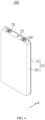
FIG. 1 is a schematic structural diagram of an electrochemical device according to an embodiment of this application. -
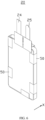
FIG. 2 is a schematic structural diagram of an electrode assembly according to an embodiment of this application. -
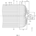
FIG. 3 is a partial view of a III-III section of the electrochemical device shown inFIG. 1 . -
FIG. 4 is a schematic structural diagram of an extended embodiment of the electrochemical device shown inFIG. 1 . -
FIG. 5 is a partial cross-sectional view of an extended embodiment of the electrochemical device shown inFIG. 1 . -
FIG. 6 is a schematic structural diagram of an electrode assembly disposed with a bonding member according to an embodiment of this application. -
FIG. 7 is a structural cross-sectional view of a portion, packaged in a housing, of the electrode assembly disposed with a bonding member shown inFIG. 6 . -
FIG. 8 is a schematic structural diagram of an electric device according to an embodiment of this application. -
Electrochemical device 100 Housing 10 First housing 11 First recess 111 First chamfer 112 Second housing 12 Second recess 121 Second chamfer 122 Accommodating space 13 Connection region 14 Electrolyte solution injection hole 15 Electrode assembly 20 First electrode plate 21 Second electrode plate 22 Separator 23 First electrode terminal 24 Second electrode terminal 25 First output terminal 31 Second output terminal 32 First region 40 First portion 41 Second portion 42 Bonding member 50 Second region 60 Third portion 61 Fourth portion 62 Electric device 200 First direction X - This application will be further described with reference to the accompanying drawings in the following specific embodiments.
- The following describes the technical solutions in embodiments of this application with reference to the accompanying drawings in the embodiments of this application. Apparently, the described embodiments are only some rather than all of the embodiments of this application.
- It should be noted that when one component is assumed as being "connected to" another component, it may be connected to the another component directly or with a component possibly present therebetween. When one component is assumed as being "disposed on/in" another component, the component may be provided directly on/in the another component or with a component possibly present therebetween.
- Unless otherwise defined, all technical and scientific terms used herein shall have the same meanings as commonly understood by those skilled in the art to which this application pertains. The terms used herein in the specification of this application are for description of specific embodiments only without any intention to limit this application. The term "and/or" used herein includes any and all combinations of one or more associated items listed.
- The embodiments of this application provide an electrochemical device, including a housing and an electrode assembly. The housing includes a first housing and a second housing, where the first housing and the second housing are connected to each other to form an accommodating space. The electrode assembly is disposed within the accommodating space, where the electrode assembly includes a first electrode plate, a second electrode plate, and a separator disposed between the first electrode plate and the second electrode plate, the first electrode plate, the separator, and the second electrode plate are sequentially stacked along a first direction, the first direction is a thickness direction of the housing, and the first housing and the second housing are arranged opposite to each other along the first direction. Along the first direction, a projection of the second electrode plate is within a projection of the first electrode plate, the projection of the first electrode plate is within a projection of the separator, and the projection of the separator is within a projection of the accommodating space. Along a direction perpendicular to the first direction, the separator extends beyond the first electrode plate, and an end of a portion of the separator extending beyond the first electrode plate, together with the first housing and the second housing, enclose a first region.
- In the above electrochemical device, the separator is disposed within the accommodating space of the housing, and the end of the portion of the separator extending beyond the first electrode plate and the second electrode plate, together with the first housing and the second housing, enclose the first region. This can prevent the separator from entering the connection region of the first housing and the second housing, reducing the impact of the separator on housing packaging, and improving the yield rate of the electrochemical device.
- The following further describes the embodiments of this application with reference to the accompanying drawings.
- As shown in
FIGs. 1 ,2 , and3 , embodiments of this application provide anelectrochemical device 100, including ahousing 10 and anelectrode assembly 20, where theelectrode assembly 20 is disposed within thehousing 10. Theelectrode assembly 20 includes afirst electrode plate 21, asecond electrode plate 22, aseparator 23, afirst electrode terminal 24, and asecond electrode terminal 25, where theseparator 23 is disposed between thefirst electrode plate 21 and thesecond electrode plate 22, and thefirst electrode plate 21, theseparator 23, and thesecond electrode plate 22 are sequentially stacked along a first direction X, where the first direction X is a thickness direction of thehousing 10. Thefirst electrode terminal 24 is electrically connected to thefirst electrode plate 21, and thesecond electrode terminal 25 is electrically connected to thesecond electrode plate 22. Thefirst electrode terminal 24 and thesecond electrode terminal 25 are configured to electrically connect to external devices, enabling theelectrochemical device 100 to charge and discharge. - In one embodiment, the
housing 10 is provided with an electrolytesolution injection hole 15, where the electrolytesolution injection hole 15 is configured for injecting electrolyte solution into thehousing 10 after theelectrode assembly 20 is packaged within thehousing 10. - In one embodiment, the
electrochemical device 100 further includes afirst output terminal 31 and asecond output terminal 32, where thefirst output terminal 31 is electrically connected to thefirst electrode terminal 24 and exposed outside thehousing 10, and thesecond output terminal 32 is electrically connected to thesecond electrode terminal 25 and exposed outside thehousing 10. Thefirst output terminal 31 and thesecond output terminal 32 are configured to electrically connect to external devices, enabling theelectrochemical device 100 to charge and discharge. - In one embodiment, the
electrochemical device 100 is a pouch battery. Optionally, thehousing 10 includes an aluminum plastic film. In one embodiment, theelectrochemical device 100 is a hard shell battery. Optionally, thehousing 10 includes a steel housing. As an example, further description will be provided in the following with theelectrochemical device 100 being a hard shell battery and thehousing 10 including a steel housing. - In one embodiment, the
first output terminal 31 is located on an outer surface of thehousing 10 and is electrically connected to thehousing 10. Thefirst electrode terminal 24 is electrically connected to thefirst output terminal 31 through its electrical connection to thehousing 10. In one embodiment, thefirst output terminal 31 is welded to the outer surface of thehousing 10. In one embodiment, thefirst electrode terminal 24 is welded to an inner surface of thehousing 10. In one embodiment, thefirst output terminal 31 is a nickel sheet. - In one embodiment, part of the
second output terminal 32 is located within thehousing 10 and connected to thesecond electrode terminal 25, and part of thesecond output terminal 32 is located outside thehousing 10. The part of thesecond output terminal 32 located outside thehousing 10 is configured to connect to external devices. Theelectrochemical device 100 further includes a second sealing member (not shown in the figure), where the second sealing member is connected to thesecond output terminal 32 and thehousing 10, and the second sealing member can prevent thesecond output terminal 32 from coming into contact with thehousing 10, thereby reducing the risk of a short circuit caused by thesecond output terminal 32 electrically connecting to thehousing 10. In one embodiment, thesecond output terminal 32 is a pole. - Referring to
FIGs. 2 and4 , in one embodiment, part of thefirst output terminal 31 is located within thehousing 10 and connected to thefirst electrode terminal 24, and part of thefirst output terminal 31 is located outside thehousing 10. The part of thefirst output terminal 31 located outside thehousing 10 is configured to connect to external devices. Theelectrochemical device 100 further includes a first sealing member (not shown in the figure), where the first sealing member is connected to thefirst output terminal 31 and thehousing 10, and the first sealing member can prevent thefirst output terminal 31 from coming into contact with thehousing 10, thereby reducing the risk of a short circuit caused by thefirst output terminal 31 electrically connecting to thehousing 10. In one embodiment, thefirst output terminal 31 is a pole. - As an example, further description will be provided in the following with the
first output terminal 31 being a nickel sheet and thesecond output terminal 32 being a pole. - Referring to
FIGs. 1 and3 , in one embodiment, one of thefirst electrode plate 21 and thesecond electrode plate 22 is a positive electrode plate, and the other is a negative electrode plate. As an example, further description will be provided in the following with thefirst electrode plate 21 being a negative electrode plate and thesecond electrode plate 22 being a positive electrode plate. - In one embodiment, the
first electrode plate 21 includes a first current collector and a first active material layer, where the first active material layer is disposed on a surface of the first current collector. Optionally, the first current collector is made of copper foil. Optionally, the first active material layer is made of graphite. - In one embodiment, the
second electrode plate 22 includes a second current collector and a second active material layer, where the second active material layer is disposed on a surface of the second current collector. Optionally, the second current collector is made of aluminum foil. Optionally, the second active material layer is made of lithium cobalt oxide. - The
housing 10 includes afirst housing 11 and asecond housing 12, where thefirst housing 11 and thesecond housing 12 are opposite to each other arranged along the first direction X, and thefirst housing 11 and thesecond housing 12 are connected to each other to form anaccommodating space 13. Theelectrode assembly 20 is disposed within theaccommodating space 13. - In one embodiment, the
first electrode plate 21, theseparator 23, and thesecond electrode plate 22 are each provided in plurality, and oneseparator 23 is disposed between any adjacentfirst electrode plate 21 andsecond electrode plate 22. All thefirst electrode plates 21,separators 23, andsecond electrode plates 22 are stacked. - In one embodiment, along the first direction X, the electrode plate on the outermost side is the
first electrode plate 21, and the first current collector of thefirst electrode plate 21 located on the outermost side is in contacting connection with the inner surface of thehousing 10. - In one embodiment, the
first electrode terminal 24 connects all thefirst electrode plates 21. In one embodiment, thesecond electrode terminal 25 is connected to all thesecond electrode plates 22. - Along the first direction X, a projection of the
second electrode plate 22 is within a projection of thefirst electrode plate 21, which can reduce the risk of lithium precipitation. - Along the first direction X, the projection of the
first electrode plate 21 is within a projection of theseparator 23, and along the direction perpendicular to the first direction X, theseparator 23 extends beyond thefirst electrode plate 21, which can reduce the risk of a short circuit between afirst electrode plate 21 and an adjacentsecond electrode plate 22. In this application, the direction perpendicular to the first direction X refers to all directions on a plane perpendicular to the thickness direction of thehousing 10. - Along the first direction X, the projection of the
separator 23 is within a projection of theaccommodating space 13. Along the direction perpendicular to the first direction X, ends of portions of a plurality of layers ofseparator 23 extending beyond thefirst electrode plate 21, together with thefirst housing 11 and thesecond housing 12, enclose afirst region 40. The presence of thefirst region 40 can reduce the risk of theseparator 23 entering theconnection region 14 of thefirst housing 11 and thesecond housing 12, reducing the impact of theseparator 23 on thehousing 10 packaging, and improving the yield rate of theelectrochemical device 100. In this application, theconnection region 14 of thefirst housing 11 and thesecond housing 12 refers to the region where thefirst housing 11 and thesecond housing 12 are in contact with each other. When packaging thehousing 10, thefirst housing 11 and thesecond housing 12 are usually sealingly connected in theconnection region 14 of thefirst housing 11 and thesecond housing 12. If part of theseparator 23 enters the sealingly connected region of thefirst housing 11 and thesecond housing 12, it may cause failure in the sealing of thehousing 10, resulting in the scrapping of theelectrochemical device 100. - In one embodiment, the
first region 40 includes afirst portion 41 and asecond portion 42. Along the first direction X, a projection of thefirst portion 41 is within the projection of theseparator 23, and a projection of thesecond portion 42 is outside the projection of theseparator 23. - In one embodiment, using
electrode assembly 20 as the object of illustration, along the direction perpendicular to the first direction X, thefirst portion 41 is formed by the ends of the plurality of layers ofseparator 23 being recessed along a direction approaching thefirst electrode plate 21 and thesecond electrode plate 22. In one embodiment, thefirst portion 41 is formed by shaping part of theseparators 23. Specifically, after all thefirst electrode plates 21,separators 23, andsecond electrode plates 22 are stacked, a shaping process is used to form recessed notches at the ends of part of theseparators 23, thereby forming thefirst portion 41. In one embodiment, the shaping process for theseparator 23 includes but is not limited to hot stamping, laser cutting, and mechanical cutting. - In one embodiment, the
second portion 42 is formed in the chamfered part of thefirst housing 11 and/or thesecond housing 12. Along the direction perpendicular to the first direction X, one side of thesecond portion 42 is thefirst portion 41, and another side of thesecond portion 42 is theconnection region 14 of thefirst housing 11 and thesecond housing 12. - In one embodiment, along the first direction X, a length of the
first region 40 is L1 (that is, a maximum length of the first region in the first direction), where L1 > 0. Along the direction perpendicular to the first direction X, a width of thefirst region 40 is W1 (that is, a maximum width of the first region along the direction perpendicular to the first direction), where W1 > 0. - In one embodiment, along the first direction X, the maximum width of the
first region 40 is at theconnection region 14 of thefirst housing 11 and thesecond housing 12, which can further reduce the risk of theseparator 23 entering theconnection region 14. Moreover, along the first direction X, starting from aconnection region 14 of thefirst housing 11 and thesecond housing 12 and extending along a direction away from theconnection region 14, the width of thefirst region 40 gradually decreases until it reaches zero, allowing the ends of part of theseparators 23 to abut against thefirst housing 11 and/or thesecond housing 12, reducing a risk of relative displacement between theelectrode assembly 20 and thehousing 10, and improving the anti-vibration performance of theelectrochemical device 100. - In one embodiment, along the first direction X, a length of the
accommodating space 13 is H, where H ≥ 2 * L1, which allowsmore separators 23 to abut against thefirst housing 11 and/or thesecond housing 12, reducing the risk of relative displacement between theelectrode assembly 20 and thehousing 10, and improving the anti-vibration performance of theelectrochemical device 100. In one embodiment, H/3 ≤ L1 ≤ H/2. Optionally, L1 = H/3. - In one embodiment, along the direction perpendicular to the first direction X, a minimum distance between the
first portion 41 and thefirst electrode plate 21 is D, where D ≥ 0.45 mm, allowing the portions of theseparators 23 extending beyond thefirst electrode plate 21 to have an insulating effect, reducing the risk of a short circuit between afirst electrode plate 21 and an adjacentsecond electrode plate 22. In one embodiment, the minimum distance D between thefirst portion 41 and thefirst electrode plate 21 is a safety length by which theseparator 23 extends beyond thefirst electrode plate 21. Optionally, a value of D is one of 0.45 mm, 0.5 mm, and 0.55 mm. - In one embodiment, along the direction perpendicular to the first direction X, a maximum length by which the
separator 23 extends beyond thefirst electrode plate 21 is W, where W > D and W > 2 * W1, reducing the impact of thefirst region 40 on the safety length by which theseparator 23 extends beyond thefirst electrode plate 21. - In one embodiment, the
second housing 12 has asecond recess 121, and thefirst housing 11 covers thesecond housing 12, thereby forming theaccommodating space 13 with thesecond recess 121. Along the direction perpendicular to the first direction X, projections of theaccommodating space 13 and thefirst region 40 are within the projection of thesecond housing 12, and the ends of part of theseparators 23 abut against thesecond housing 12. In one embodiment, the part of thesecond housing 12 located between theaccommodating space 13 and theconnection region 14 has asecond chamfer 122. Along the first direction X, thesecond portion 42 is located between thesecond chamfer 122 and thefirst housing 11. In one embodiment, thesecond chamfer 122 is rounded, which can reduce the impact of thesecond chamfer 122 on theseparator 23, and reduce a risk of thesecond chamfer 122 piercing theseparator 23. - As shown in
FIG. 5 , in one embodiment, thefirst housing 11 has afirst recess 111, and thesecond housing 12 has asecond recess 121. Thefirst housing 11 and thesecond housing 12 are snap-fitted to form theaccommodating space 13. Along the direction perpendicular to the first direction X, a portion of the projection of theaccommodating space 13 is within the projection of thefirst housing 11, and another portion of the projection of theaccommodating space 13 is within the projection of thesecond housing 12. A portion of the projection of thefirst region 40 is within the projection of thefirst housing 11, and another portion of the projection of thefirst region 40 is within the projection of thesecond housing 12. In one embodiment, the part of thefirst housing 11 located between thefirst recess 111 and theconnection region 14 has a first chamfer 112, and the part of thesecond housing 12 located between thesecond recess 121 and theconnection region 14 has asecond chamfer 122. Along the first direction X, thesecond portion 42 is located between the first chamfer 112 and thesecond chamfer 122. - In one embodiment, the first chamfer 112 is rounded, which can reduce the impact of the first chamfer 112 on the
separator 23, and reduce a risk of the first chamfer 112 piercing theseparator 23. In one embodiment, thesecond chamfer 122 is rounded, which can reduce the impact of thesecond chamfer 122 on theseparator 23, and reduce the risk of thesecond chamfer 122 piercing theseparator 23. - As an example, further description will be provided in the following with the
first housing 11 covering thesecond housing 12 and thesecond recess 121 forming theaccommodating space 13. - Referring to
FIG. 3 , in one embodiment, along the direction perpendicular to the first direction X, theseparators 23 abutting against thesecond housing 12 are in a state of being compressed and deformed, which can further improve the stability of the connection between theelectrode assembly 20 and thehousing 10, reducing the risk of relative displacement between theelectrode assembly 20 and thehousing 10, and improving the anti-vibration performance of theelectrochemical device 100. - In one embodiment, along the first direction X, the portions of the
separators 23 compressed and deformed by thesecond housing 12 all bend toward thesecond portion 42. Along the direction perpendicular to the first direction X, the plurality ofseparators 23 in the bent region are sequentially stacked, which can reduce the risk of the ends of thefirst electrode plate 21 and thesecond electrode plate 22 piercing part of theseparators 23 and then coming into contact with thehousing 10 to cause a short circuit, improving the safety performance of theelectrochemical device 100. - As shown in
FIGs. 6 and7 , in one embodiment, theelectrochemical device 100 further includes abonding member 50, where one end of thebonding member 50 is connected to one side of theelectrode assembly 20 along the first direction X, and an opposite end of thebonding member 50 is connected to another side of theelectrode assembly 20 along the first direction X. The bondingmember 50 can increase the connection tightness of theelectrode assembly 20 along the first direction X, reducing a risk of relative displacement between thefirst electrode plate 21, theseparator 23, and thesecond electrode plate 22, improving the anti-vibration performance of theelectrode assembly 20, and improving the anti-vibration performance of theelectrochemical device 100. Optionally, the bondingmember 50 is insulating adhesive tape. - In one embodiment, the
bonding members 50 is provided in plurality, and the plurality ofbonding members 50 are spaced apart from each other along a circumferential direction of theelectrode assembly 20, fastening theelectrode assembly 20 at multiple positions, further improving the anti-vibration performance of theelectrode assembly 20, and improving the anti-vibration performance of theelectrochemical device 100. - In one embodiment, along the direction perpendicular to the first direction X, an end of the
separator 23 abuts against the bondingmember 50, which can prevent thebonding member 50 from loosening, thereby reducing the risk of relative displacement between thefirst electrode plate 21, theseparator 23, and thesecond electrode plate 22. - Referring to
FIGs. 3 and6 , in one embodiment, along the first direction X, a projection of thebonding member 50 is within the projection of theaccommodating space 13. The bondingmember 50, together with thefirst housing 11 and thesecond housing 12, enclose asecond region 60, and thesecond region 60 is within thefirst region 40. This can reduce a risk of thebonding member 50 entering theconnection region 14, reducing the impact of thebonding member 50 on thehousing 10 packaging, and improving the yield rate of theelectrochemical device 100. - In one embodiment, the
second region 60 includes athird portion 61 and afourth portion 62, where thethird portion 61 constitutes part of thefirst portion 41, and thefourth portion 62 is the same as thesecond portion 42. Along the first direction X, a projection of thethird portion 61 is within the projection of thebonding member 50, and a projection of thefourth portion 62 is outside the projection of thebonding member 50. - In one embodiment, after all the
first electrode plates 21,separators 23, andsecond electrode plates 22 are stacked, a shaping process is used to form recessed notches at the ends of part of theseparators 23. After theelectrode assembly 20 is placed into thehousing 10, the recessed notches formed at the ends of theseparators 23 constitute thefirst portion 41, and after thebonding member 50 is attached to theelectrode assembly 20, thethird portion 61 is formed within thefirst portion 41. - The
fourth portion 62 is the same as thesecond portion 42, and details are not repeated herein. - In one embodiment, along the first direction X, a length of the
second region 60 is L2, where L2 > 0. Along the direction perpendicular to the first direction X, a width of thesecond region 60 is W2, where W2 > 0. - In one embodiment, along the first direction X, the
second region 60 has a maximum width at theconnection region 14 of thefirst housing 11 and thesecond housing 12, which can further reduce the risk of theseparator 23 and/or thebonding member 50 entering theconnection region 14. Moreover, along the first direction X, starting from theconnection region 14 of thefirst housing 11 and thesecond housing 12 and extending along a direction away from theconnection region 14, the width of thesecond region 60 gradually decreases until it reaches zero, allowing the ends of part of thebonding members 50 to abut against thesecond housing 12, reducing a risk of relative displacement between theelectrode assembly 20 and thehousing 10, and improving the anti-vibration performance of theelectrochemical device 100. - In one embodiment, L2 ≤ H/2, which allows
more bonding members 50 to abut against thesecond housing 12, reducing the risk of relative displacement between theelectrode assembly 20 and thehousing 10, and improving the anti-vibration performance of theelectrochemical device 100. In one embodiment, H/3 ≤ L2 ≤ H/2. Optionally, L2 = H/3. - In one embodiment, along the direction perpendicular to the first direction X, the
separators 23 abutting against the bondingmember 50 are in a state of being compressed and deformed, which can further improve the stability of the connection between thefirst electrode plate 21, theseparator 23, and thesecond electrode plate 22, reducing the risk of relative displacement between thefirst electrode plate 21, theseparator 23, and thesecond electrode plate 22, improving the anti-vibration performance of theelectrode assembly 20, and improving the anti-vibration performance of theelectrochemical device 100. - In one embodiment, along the first direction X, the portions of the
separators 23 compressed and deformed by thebonding members 50 all bend toward thefourth portion 62. Along the direction perpendicular to the first direction X, the plurality ofseparators 23 in the bent region are sequentially stacked, which can reduce the risk of the ends of thefirst electrode plate 21 and thesecond electrode plate 22 piercing part of theseparators 23 andbonding members 50 and then coming into contact with thehousing 10 to cause a short circuit, improving the safety performance of theelectrochemical device 100. - In summary, in the
electrochemical device 100 of this application, theseparator 23 is disposed within theaccommodating space 13 of thehousing 10, and the end of the portion of theseparator 23 extending beyond thefirst electrode plate 21 and thesecond electrode plate 22, together with thefirst housing 11 and thesecond housing 12, enclose thefirst region 40. This prevents theseparator 23 from entering theconnection region 14 of thefirst housing 11 and thesecond housing 12, reducing the impact of theseparator 23 on thehousing 10 packaging, and improving the yield rate of theelectrochemical device 100. - As shown in
FIG. 8 , embodiments of this application further provide anelectric device 200, which includes theelectrochemical device 100 according to any of the above embodiments. Theelectrochemical device 100 can provide power for theelectric device 200. - In one embodiment, the
electric device 200 includes but is not limited to mobile phones, computers, tablets, digital cameras, drones, and new energy vehicles. - When the
electric device 200 of this application adopts theelectrochemical device 100 according to any of the above embodiments, the impact of theelectrochemical device 100 on theelectric device 200 due to quality issues can be reduced. - In addition, persons skilled in the art can also make other changes within the spirit of this application. Certainly, these changes made according to the spirit of this application shall fall within the scope of this application.
Claims (10)
- An electrochemical device, comprising:a housing comprising a first housing and a second housing, wherein the first housing and the second housing are connected to each other to form an accommodating space; andan electrode assembly disposed within the accommodating space; wherein the electrode assembly comprises a first electrode plate, a second electrode plate, and a separator disposed between the first electrode plate and the second electrode plate; the first electrode plate, the separator, and the second electrode plate are sequentially stacked along a first direction, the first direction is a thickness direction of the housing, and the first housing and the second housing are arranged opposite to each other along the first direction; whereinalong the first direction, a projection of the second electrode plate is within a projection of the first electrode plate, the projection of the first electrode plate is within a projection of the separator, and the projection of the separator is within a projection of the accommodating space; andalong a direction perpendicular to the first direction, the separator extends beyond the first electrode plate, and an end of a portion of the separator extending beyond the first electrode plate, together with the first housing and the second housing, enclose a first region.
- The electrochemical device according to claim 1, whereinalong the first direction, at least part of a projection of the first region is within the projection of the separator, and a length of the first region is L1, wherein L1 > 0; andalong the direction perpendicular to the first direction, a width of the first region is W1, wherein W1 > 0.
- The electrochemical device according to claim 2, whereinalong the first direction, starting from a connection region of the first housing and the second housing and extending along a direction away from the connection region, the width W1 of the first region gradually decreases; andalong the direction perpendicular to the first direction, a maximum length by which the separator extends beyond the first electrode plate is W, wherein W > 2 * W1.
- The electrochemical device according to claim 2, wherein along the first direction, a length of the accommodating space is H, wherein H ≥ 2 * L1.
- The electrochemical device according to claim 1, wherein along the direction perpendicular to the first direction, a minimum distance between the first region and the first electrode plate is D, wherein D ≥ 0.45 mm.
- The electrochemical device according to claim 1, wherein along the direction perpendicular to the first direction, the separator is connected to the first housing and/or the second housing.
- The electrochemical device according to claim 1, further comprising a bonding member, wherein one end of the bonding member is connected to one side of the electrode assembly along the first direction, and an opposite end of the bonding member is connected to another side of the electrode assembly along the first direction; whereinalong the direction perpendicular to the first direction, an end of the separator abuts against the bonding member;along the first direction, a projection of the bonding member is within the projection of the accommodating space; andthe bonding member, together with the first housing and the second housing, enclose a second region, and the second region is within the first region.
- The electrochemical device according to claim 7, wherein along the direction perpendicular to the first direction, a projection of the second region is within the projection of the bonding member, and part of the bonding members abut against the first housing and/or the second housing.
- The electrochemical device according to claim 7, whereinthe first electrode plate, the separator, and the second electrode plate are each provided in plurality, and at least one separator is disposed between any adjacent first electrode plate and second electrode plate; andalong the first direction, at each of two sides of the electrode assembly is the first electrode plate, and two ends of the bonding member are respectively connected to the first electrode plates at the two sides of the electrode assembly.
- An electric device, comprising the electrochemical device according to any one of claims 1 to 9.
Applications Claiming Priority (1)
| Application Number | Priority Date | Filing Date | Title |
|---|---|---|---|
| PCT/CN2022/099893 WO2023245350A1 (en) | 2022-06-20 | 2022-06-20 | Electrochemical device and electric device |
Publications (2)
| Publication Number | Publication Date |
|---|---|
| EP4528863A1 true EP4528863A1 (en) | 2025-03-26 |
| EP4528863A4 EP4528863A4 (en) | 2025-10-22 |
Family
ID=86519516
Family Applications (1)
| Application Number | Title | Priority Date | Filing Date |
|---|---|---|---|
| EP22947131.3A Pending EP4528863A4 (en) | 2022-06-20 | 2022-06-20 | ELECTROCHEMICAL DEVICE AND ELECTRICAL DEVICE |
Country Status (4)
| Country | Link |
|---|---|
| US (1) | US20250118864A1 (en) |
| EP (1) | EP4528863A4 (en) |
| CN (1) | CN116210122B (en) |
| WO (1) | WO2023245350A1 (en) |
Family Cites Families (13)
| Publication number | Priority date | Publication date | Assignee | Title |
|---|---|---|---|---|
| JP4031635B2 (en) * | 2001-11-08 | 2008-01-09 | Tdk株式会社 | Electrochemical devices |
| JP2005044583A (en) * | 2003-07-25 | 2005-02-17 | Toshiba Corp | Thin secondary battery |
| JP4932263B2 (en) * | 2005-01-28 | 2012-05-16 | Necエナジーデバイス株式会社 | Multilayer secondary battery and manufacturing method thereof |
| CN100349322C (en) * | 2005-12-09 | 2007-11-14 | 中信国安盟固利新能源科技有限公司 | Cylindrical flexible packed lithium ion storage cell with aluminum-plastic composite film |
| KR20160105124A (en) * | 2015-02-27 | 2016-09-06 | 주식회사 엘지화학 | Pouch type secondary battery |
| JP6101726B2 (en) * | 2015-03-25 | 2017-03-22 | オートモーティブエナジーサプライ株式会社 | Lithium ion secondary battery |
| CN205376661U (en) * | 2016-01-19 | 2016-07-06 | 东莞新能源科技有限公司 | Lamination formula battery |
| JP7374204B2 (en) * | 2019-03-01 | 2023-11-06 | 青▲海▼▲時▼代新能源科技有限公司 | secondary battery |
| KR20230031974A (en) * | 2020-09-28 | 2023-03-07 | 닝더 엠프렉스 테크놀로지 리미티드 | battery |
| CN113597683A (en) * | 2020-09-30 | 2021-11-02 | 宁德新能源科技有限公司 | Electrode assembly, battery and preparation method of electrode assembly |
| CN112687831B (en) * | 2020-12-24 | 2022-03-22 | 宁德新能源科技有限公司 | Electrode assembly and secondary battery |
| CN113097430B (en) * | 2021-03-30 | 2022-07-29 | 宁德新能源科技有限公司 | Electrochemical device and electronic device |
| CN114430095B (en) * | 2022-04-06 | 2022-07-08 | 宁德新能源科技有限公司 | Electrochemical device and electronic apparatus |
-
2022
- 2022-06-20 CN CN202280005985.XA patent/CN116210122B/en active Active
- 2022-06-20 EP EP22947131.3A patent/EP4528863A4/en active Pending
- 2022-06-20 WO PCT/CN2022/099893 patent/WO2023245350A1/en not_active Ceased
-
2024
- 2024-12-19 US US18/987,069 patent/US20250118864A1/en active Pending
Also Published As
| Publication number | Publication date |
|---|---|
| CN116210122A (en) | 2023-06-02 |
| WO2023245350A1 (en) | 2023-12-28 |
| EP4528863A4 (en) | 2025-10-22 |
| CN116210122B (en) | 2025-04-04 |
| CN116210122A8 (en) | 2024-05-21 |
| US20250118864A1 (en) | 2025-04-10 |
Similar Documents
| Publication | Publication Date | Title |
|---|---|---|
| US8283067B2 (en) | Electric energy storage device and manufacturing method thereof | |
| CN202308182U (en) | Secondary battery | |
| EP2958177B1 (en) | Electrode assembly having rounded corners | |
| US11271274B2 (en) | Secondary battery | |
| US12463275B2 (en) | Electrode assembly including plastic member applied to electrode tabs-lead coupling portion and secondary battery including the same | |
| EP3703160B1 (en) | Secondary battery | |
| US20110076544A1 (en) | Stack type battery | |
| CN113366682A (en) | Electrochemical device and electronic device | |
| JP4438784B2 (en) | Power storage device | |
| US20230026628A1 (en) | Electrochemical apparatus and electronic apparatus | |
| EP4123795B1 (en) | Battery including exterior material and method for manufacturing battery including exterior material | |
| US20240030521A1 (en) | Battery and electric device | |
| US20230246313A1 (en) | Secondary battery | |
| KR20150013014A (en) | Electrode assembly, and rechargeable battery | |
| US20220223918A1 (en) | Secondary battery and battery module | |
| KR100277638B1 (en) | Electrode assembly manufacturing method and electrode assembly and battery using the electrode assembly | |
| US20250118864A1 (en) | Electrochemical device and electric device | |
| CN115441102B (en) | Exterior body and battery | |
| EP4604277A1 (en) | Secondary battery and method of manufacturing a secondary battery | |
| CN222995471U (en) | Batteries and electronic devices | |
| US20250087834A1 (en) | Electrode assembly and rechargeable battery including the same | |
| US20260024855A1 (en) | Battery cell including electrode tab, battery module including the same, and battery cell manufacturing method | |
| CN116169439B (en) | battery cells | |
| US20240413472A1 (en) | Secondary battery and battery assembly | |
| KR20260066964A (en) | Secondary battery and case for secondary battery |
Legal Events
| Date | Code | Title | Description |
|---|---|---|---|
| STAA | Information on the status of an ep patent application or granted ep patent |
Free format text: STATUS: THE INTERNATIONAL PUBLICATION HAS BEEN MADE |
|
| PUAI | Public reference made under article 153(3) epc to a published international application that has entered the european phase |
Free format text: ORIGINAL CODE: 0009012 |
|
| STAA | Information on the status of an ep patent application or granted ep patent |
Free format text: STATUS: REQUEST FOR EXAMINATION WAS MADE |
|
| 17P | Request for examination filed |
Effective date: 20241218 |
|
| AK | Designated contracting states |
Kind code of ref document: A1 Designated state(s): AL AT BE BG CH CY CZ DE DK EE ES FI FR GB GR HR HU IE IS IT LI LT LU LV MC MK MT NL NO PL PT RO RS SE SI SK SM TR |
|
| DAV | Request for validation of the european patent (deleted) | ||
| DAX | Request for extension of the european patent (deleted) | ||
| A4 | Supplementary search report drawn up and despatched |
Effective date: 20250919 |
|
| RIC1 | Information provided on ipc code assigned before grant |
Ipc: H01M 10/04 20060101AFI20250915BHEP Ipc: H01M 50/46 20210101ALI20250915BHEP Ipc: H01M 50/406 20210101ALI20250915BHEP Ipc: H01M 10/0585 20100101ALI20250915BHEP Ipc: H01M 50/105 20210101ALI20250915BHEP Ipc: H01M 50/463 20210101ALI20250915BHEP Ipc: H01M 50/471 20210101ALI20250915BHEP Ipc: H01M 50/103 20210101ALI20250915BHEP Ipc: H01M 50/176 20210101ALI20250915BHEP Ipc: H01M 50/55 20210101ALI20250915BHEP Ipc: H01M 50/553 20210101ALI20250915BHEP |