EP4528716A1 - Motor vehicle with improved active road noise cancelling apparatus - Google Patents
Motor vehicle with improved active road noise cancelling apparatus Download PDFInfo
- Publication number
- EP4528716A1 EP4528716A1 EP24201876.0A EP24201876A EP4528716A1 EP 4528716 A1 EP4528716 A1 EP 4528716A1 EP 24201876 A EP24201876 A EP 24201876A EP 4528716 A1 EP4528716 A1 EP 4528716A1
- Authority
- EP
- European Patent Office
- Prior art keywords
- motor vehicle
- control input
- vehicle according
- input signal
- corresponding wall
- Prior art date
- Legal status (The legal status is an assumption and is not a legal conclusion. Google has not performed a legal analysis and makes no representation as to the accuracy of the status listed.)
- Pending
Links
Images



Classifications
-
- G—PHYSICS
- G10—MUSICAL INSTRUMENTS; ACOUSTICS
- G10K—SOUND-PRODUCING DEVICES; METHODS OR DEVICES FOR PROTECTING AGAINST, OR FOR DAMPING, NOISE OR OTHER ACOUSTIC WAVES IN GENERAL; ACOUSTICS NOT OTHERWISE PROVIDED FOR
- G10K11/00—Methods or devices for transmitting, conducting or directing sound in general; Methods or devices for protecting against, or for damping, noise or other acoustic waves in general
- G10K11/16—Methods or devices for protecting against, or for damping, noise or other acoustic waves in general
- G10K11/175—Methods or devices for protecting against, or for damping, noise or other acoustic waves in general using interference effects; Masking sound
- G10K11/178—Methods or devices for protecting against, or for damping, noise or other acoustic waves in general using interference effects; Masking sound by electro-acoustically regenerating the original acoustic waves in anti-phase
- G10K11/1787—General system configurations
- G10K11/17879—General system configurations using both a reference signal and an error signal
-
- G—PHYSICS
- G10—MUSICAL INSTRUMENTS; ACOUSTICS
- G10K—SOUND-PRODUCING DEVICES; METHODS OR DEVICES FOR PROTECTING AGAINST, OR FOR DAMPING, NOISE OR OTHER ACOUSTIC WAVES IN GENERAL; ACOUSTICS NOT OTHERWISE PROVIDED FOR
- G10K11/00—Methods or devices for transmitting, conducting or directing sound in general; Methods or devices for protecting against, or for damping, noise or other acoustic waves in general
- G10K11/16—Methods or devices for protecting against, or for damping, noise or other acoustic waves in general
- G10K11/175—Methods or devices for protecting against, or for damping, noise or other acoustic waves in general using interference effects; Masking sound
- G10K11/178—Methods or devices for protecting against, or for damping, noise or other acoustic waves in general using interference effects; Masking sound by electro-acoustically regenerating the original acoustic waves in anti-phase
- G10K11/1781—Methods or devices for protecting against, or for damping, noise or other acoustic waves in general using interference effects; Masking sound by electro-acoustically regenerating the original acoustic waves in anti-phase characterised by the analysis of input or output signals, e.g. frequency range, modes, transfer functions
- G10K11/17813—Methods or devices for protecting against, or for damping, noise or other acoustic waves in general using interference effects; Masking sound by electro-acoustically regenerating the original acoustic waves in anti-phase characterised by the analysis of input or output signals, e.g. frequency range, modes, transfer functions characterised by the analysis of the acoustic paths, e.g. estimating, calibrating or testing of transfer functions or cross-terms
- G10K11/17815—Methods or devices for protecting against, or for damping, noise or other acoustic waves in general using interference effects; Masking sound by electro-acoustically regenerating the original acoustic waves in anti-phase characterised by the analysis of input or output signals, e.g. frequency range, modes, transfer functions characterised by the analysis of the acoustic paths, e.g. estimating, calibrating or testing of transfer functions or cross-terms between the reference signals and the error signals, i.e. primary path
-
- G—PHYSICS
- G10—MUSICAL INSTRUMENTS; ACOUSTICS
- G10K—SOUND-PRODUCING DEVICES; METHODS OR DEVICES FOR PROTECTING AGAINST, OR FOR DAMPING, NOISE OR OTHER ACOUSTIC WAVES IN GENERAL; ACOUSTICS NOT OTHERWISE PROVIDED FOR
- G10K11/00—Methods or devices for transmitting, conducting or directing sound in general; Methods or devices for protecting against, or for damping, noise or other acoustic waves in general
- G10K11/16—Methods or devices for protecting against, or for damping, noise or other acoustic waves in general
- G10K11/175—Methods or devices for protecting against, or for damping, noise or other acoustic waves in general using interference effects; Masking sound
- G10K11/178—Methods or devices for protecting against, or for damping, noise or other acoustic waves in general using interference effects; Masking sound by electro-acoustically regenerating the original acoustic waves in anti-phase
- G10K11/1785—Methods, e.g. algorithms; Devices
- G10K11/17857—Geometric disposition, e.g. placement of microphones
-
- G—PHYSICS
- G10—MUSICAL INSTRUMENTS; ACOUSTICS
- G10K—SOUND-PRODUCING DEVICES; METHODS OR DEVICES FOR PROTECTING AGAINST, OR FOR DAMPING, NOISE OR OTHER ACOUSTIC WAVES IN GENERAL; ACOUSTICS NOT OTHERWISE PROVIDED FOR
- G10K11/00—Methods or devices for transmitting, conducting or directing sound in general; Methods or devices for protecting against, or for damping, noise or other acoustic waves in general
- G10K11/16—Methods or devices for protecting against, or for damping, noise or other acoustic waves in general
- G10K11/175—Methods or devices for protecting against, or for damping, noise or other acoustic waves in general using interference effects; Masking sound
- G10K11/178—Methods or devices for protecting against, or for damping, noise or other acoustic waves in general using interference effects; Masking sound by electro-acoustically regenerating the original acoustic waves in anti-phase
- G10K11/1781—Methods or devices for protecting against, or for damping, noise or other acoustic waves in general using interference effects; Masking sound by electro-acoustically regenerating the original acoustic waves in anti-phase characterised by the analysis of input or output signals, e.g. frequency range, modes, transfer functions
- G10K11/17821—Methods or devices for protecting against, or for damping, noise or other acoustic waves in general using interference effects; Masking sound by electro-acoustically regenerating the original acoustic waves in anti-phase characterised by the analysis of input or output signals, e.g. frequency range, modes, transfer functions characterised by the analysis of the input signals only
- G10K11/17823—Reference signals, e.g. ambient acoustic environment
-
- G—PHYSICS
- G10—MUSICAL INSTRUMENTS; ACOUSTICS
- G10K—SOUND-PRODUCING DEVICES; METHODS OR DEVICES FOR PROTECTING AGAINST, OR FOR DAMPING, NOISE OR OTHER ACOUSTIC WAVES IN GENERAL; ACOUSTICS NOT OTHERWISE PROVIDED FOR
- G10K2210/00—Details of active noise control [ANC] covered by G10K11/178 but not provided for in any of its subgroups
- G10K2210/10—Applications
- G10K2210/128—Vehicles
- G10K2210/1282—Automobiles
-
- G—PHYSICS
- G10—MUSICAL INSTRUMENTS; ACOUSTICS
- G10K—SOUND-PRODUCING DEVICES; METHODS OR DEVICES FOR PROTECTING AGAINST, OR FOR DAMPING, NOISE OR OTHER ACOUSTIC WAVES IN GENERAL; ACOUSTICS NOT OTHERWISE PROVIDED FOR
- G10K2210/00—Details of active noise control [ANC] covered by G10K11/178 but not provided for in any of its subgroups
- G10K2210/10—Applications
- G10K2210/128—Vehicles
- G10K2210/1282—Automobiles
- G10K2210/12821—Rolling noise; Wind and body noise
-
- G—PHYSICS
- G10—MUSICAL INSTRUMENTS; ACOUSTICS
- G10K—SOUND-PRODUCING DEVICES; METHODS OR DEVICES FOR PROTECTING AGAINST, OR FOR DAMPING, NOISE OR OTHER ACOUSTIC WAVES IN GENERAL; ACOUSTICS NOT OTHERWISE PROVIDED FOR
- G10K2210/00—Details of active noise control [ANC] covered by G10K11/178 but not provided for in any of its subgroups
- G10K2210/10—Applications
- G10K2210/129—Vibration, e.g. instead of, or in addition to, acoustic noise
- G10K2210/1291—Anti-Vibration-Control, e.g. reducing vibrations in panels or beams
-
- G—PHYSICS
- G10—MUSICAL INSTRUMENTS; ACOUSTICS
- G10K—SOUND-PRODUCING DEVICES; METHODS OR DEVICES FOR PROTECTING AGAINST, OR FOR DAMPING, NOISE OR OTHER ACOUSTIC WAVES IN GENERAL; ACOUSTICS NOT OTHERWISE PROVIDED FOR
- G10K2210/00—Details of active noise control [ANC] covered by G10K11/178 but not provided for in any of its subgroups
- G10K2210/30—Means
- G10K2210/321—Physical
- G10K2210/3211—Active mounts for vibrating structures with means to actively suppress the vibration, e.g. for vehicles
Definitions
- the invention relates to a motor vehicle provided with an active noise cancelling apparatus and more specifically road noise, i.e. the noise perceptible in the passenger compartment substantially or to a greater extent caused by the rolling of the tyres on the road.
- the apparatus is provided in turn with specific transducers, a control unit configured to receive the signals generated by the transducers, and sound emitting devices controlled by the control unit based on the received signals according to a control scheme for emitting sounds inside the passenger compartment of the motor vehicle.
- the emitted sounds are adapted to superpose the road noise perceptible in the passenger compartment with an effect of reducing or cancelling the road noise.
- the transducers can include for example sound pressure sensors, such as microphones, configured to detect a residual of the road noise in the passenger compartment, also called error, and possibly in addition vibration sensors configured to detect quantities indicative of vibrations at the supposed sources of the road noise, i.e. zones in the proximity of the wheels or more in general of the four corners of the motor vehicle (substantially considered as a rectangle in plan view).
- sound pressure sensors such as microphones
- vibration sensors configured to detect quantities indicative of vibrations at the supposed sources of the road noise, i.e. zones in the proximity of the wheels or more in general of the four corners of the motor vehicle (substantially considered as a rectangle in plan view).
- the vibration sensors such as accelerometers and strain gauges, or more precisely their sensible members are generally placed near the wheels or the four corners, for example at the upper supports of the suspensions of the wheels or on the wheel hubs.
- the sound emitting devices are normally electroacoustic transducers or loudspeakers integrated in the upholstery of the passenger compartment and configured to emit the sounds directly in the passenger compartment.
- control scheme most commonly adopted by the control unit is a scheme of predictive type or more precisely called feedforward.
- the signals related to the quantities detected by the vibration sensors form a reference signal, which is provided together with a signal representative of the error as inputs of an adaptive filter of the class of the least mean squares algorithms, from which a control input is obtained at the output for the sound emitting devices, by means of which the sound emitting devices progressively reduce the error.
- the reference signal is generally considered very important as it represents an additional piece of information with respect to the sole piece of information about the error, by means of which it is possible to adopt only a feedback control scheme.
- An object of the invention is to satisfy the need set forth above, preferably in a simple and repeatable manner.
- the object is achieved by a motor vehicle according to claim 1.
- reference numeral 1 is used to indicate, as a whole, a motor vehicle.
- the motor vehicle 1 comprises a body 2, in turn including a chassis 3 ( Figure 7 ) and a bodywork 4 carried by the chassis 3 and defining the outer surfaces of the motor vehicle 1.
- the motor vehicle 1 comprises a plurality of wheels 5, (only two of which are illustrated in Figure 1 ).
- the wheels 5 are coupled to the body 2 or more precisely to the chassis 3 by means of suspensions of known type and not illustrated.
- the body 2 or more precisely the bodywork 4 comprises a plurality of walls delimiting a passenger compartment 6 of the motor vehicle 1.
- the passenger compartment 6 is illustrated in Figure 6 and is configured to accommodate one or more passengers, among whom a driver 7.
- the passenger compartment 6 comprises a position (for example comprising a seat for the driver 7 and a steering wheel of the motor vehicle 1) for accommodating the driver 7.
- the walls comprise the windows of the motor vehicle 1, among which in particular a windshield 9, side windows 10a, 10b, and a rear window 11.
- the side window 10a is at the front with respect to the side window 10b.
- the side window 10a is coupled to a door 2b of the body 2 in a sliding manner on an inner volume of the door 2b, with respect to the door 2b.
- the side window 10a has a hidden portion 10c, which is arranged (in particular always) in the inner volume of the door 2b, for example regardless of the position of the side window 10a with respect to the door 2b.
- the side window 10b is fixed with respect to the body 2.
- the inner volume of the door 2b is invisible from the outside of the motor vehicle 1.
- the wall comprising the rear window 11 comprises more in general a hatchback door 12, in turn comprising the rear window 11 and a contour band 13 perimeterally contouring the rear window 11, namely contouring at least a portion of the perimeter of the rear window 11.
- the contour band 13 extends in a loop all around the rear window 11, thereby forming a closed contour.
- the contour band 13 is non-transparent or (in particular completely) opaque, whereby, in other words, the view through the contour band 13 is substantially inhibited, in particular both from the inside of the passenger compartment 6, and from the outside of the motor vehicle 1.
- the rear window 11 is preferably transparent or has at least a non-zero degree of transparency, at least from the inside of the passenger compartment 6 or also from the outside of the motor vehicle 1, although not necessarily, because the rear window 11 could be opaque both from the inside of the passenger compartment 6, and from the outside of the motor vehicle 1.
- Windows are known, in fact, that are opaque from the outside and transparent from the inside or windows are known that are even opaque both from the inside and from the outside.
- any one among the walls delimiting the passenger compartment 6 any one of these walls could in fact comprise a corresponding window like the rear window 11 (since the rear window 11 is a type of window, and not with the meaning of identical to the rear window 11) and a contour band like the contour band 13.
- the contour band and the window can in general be part of one single body or be made in one single piece, i.e. be seamlessly fixed to each other.
- one of the walls delimiting the passenger compartment 6 comprises the windshield 9 and a related contour band 14.
- another one of the walls delimiting the passenger compartment 6 is or comprises a roof 8 of the motor vehicle 1, which in turn comprises a window 15 and a contour band 16.
- contour bands 13, 14, 16 can share properties similar to one another, i.e. can be (in particular completely) opaque and contour the entire perimeter of the rear window 11, of the windshield 9, and of the roof 8, respectively with respective looped configurations; however, each one of the contour bands 13, 14, 16 could more generally also contour only a portion of the perimeter.
- the roof 8 could comprise or be defined by a sheet, in particular opaque, instead of having the window 15. This could be valid, for example, also for the wall comprising the rear window 11 or the wall comprising one of the side windows 10a, 10b.
- the walls delimiting the passenger compartment 6 have respective inner surfaces 17, which directly face the passenger compartment 6 or, alternatively, are covered with a motor vehicle interior trim layer, for example made of leather, fabric, or plastic material.
- a motor vehicle interior trim layer for example made of leather, fabric, or plastic material.
- this aspect, namely having the inner surfaces 17, is valid specifically individually for each one of the walls comprising the windshield 9, the windows 10a, 10b, the rear window 11, as well as for the roof 8.
- this aspect, namely having the inner surfaces 17, could be valid also individually for each one of the walls mentioned in this paragraph in the absence of windows, i.e. respectively in the absence of the windshield 9, the windows 10a, 10b, the rear window 11, or more precisely when completely opaque, for example as defined by respective sheets. Therefore, this could be valid more specifically also for the roof 8 in the case where it is defined by a sheet.
- the walls with the inner surfaces 17 could have, each one in an independent manner, corresponding outer surfaces 18 directly exposed on the outside of the motor vehicle 1 (possibly considering a finishing paint as part of the outer surfaces 18) and/or, more in particular, could be or be defined, each one in an independent manner, by single panels with respective thicknesses extending respectively from the inner surfaces 17 to corresponding end surfaces opposite the inner surfaces 17 in the direction of the thickness.
- the end surfaces could for example coincide with the outer surfaces 18 (with the possible finishing paint included), each one in an independent manner.
- Having the outer surfaces 18 and/or the fact of being defined by single panels, possibly with the end surfaces coinciding with the outer surfaces 18, could be valid also individually for each one of the walls mentioned in this paragraph in the absence of windows, i.e. respectively in the absence of the windshield 9, the windows 10a, 10b, the rear window 11, or more precisely when completely opaque, for example as defined by respective sheets. Therefore, this could be valid more specifically also for the roof 8 in the case where it is defined by a sheet.
- the motor vehicle 1 further comprises an active road noise cancelling apparatus, which is configured to reduce or cancel at least part of the noise perceptible from the inside of the passenger compartment 6 and caused at least in part by the rolling of the wheels 5 on the roadbed during the use of the motor vehicle 1.
- an active road noise cancelling apparatus configured to reduce or cancel at least part of the noise perceptible from the inside of the passenger compartment 6 and caused at least in part by the rolling of the wheels 5 on the roadbed during the use of the motor vehicle 1.
- the apparatus comprises a plurality of actuators 120, 121, 122, 123, 124 controllable through a control input signal y.
- the control input signal y can for example be of vector or matrix type, so as to include a plurality of components respectively pertinent for the independent control of the related actuators 120, 121, 122, 123, 124, or can anyway be considered as a set of single signals respectively pertinent for the independent control of the related actuators 120, 121, 122, 123, 124.
- the actuators 120, 121, 122, 123, 124 are not all necessary, whereby their number could vary, so that also only one of the actuators 120, 121, 122, 123, 124 could be present. In the latter case, the control input signal y could be one single signal or, better, have one single component.
- the actuators 120, 121, 122, 123, 124 are respectively coupled or applied to corresponding walls among the ones delimiting the passenger compartment 6 and more in particular having the inner surfaces 17.
- the actuators 120, 121, 122, 123, 124 are controlled through the control input signal y for transmitting vibrations corresponding to the control input signal y to the corresponding walls, namely for driving into vibration the corresponding walls in a manner corresponding to the control input signal y.
- the actuators 120, 121, 122, 123, 124 transmit the vibrations to the corresponding walls, in particular directly, because respectively applied to the walls.
- the vibrations are indirectly transmitted by the walls to the passenger compartment 6, where a sound y' is generated by effect of the vibrations of the walls, namely it is produced by means of the actuators 120, 121, 122, 123, 124.
- the actuators 120, 121, 122, 123, 124 are or comprise actuators of electrodynamic or piezoelectric type.
- the actuators of electrodynamic type are actuated magnetically, i.e. operate by means of the magnetic induction principle.
- the actuators of electrodynamic type include windings immersed in a magnetic field configured so that they produce forces on the walls where the actuators of electrodynamic type are applied when passed through by electric current. The forces are proportional to the intensity of the flow of the magnetic field through the windings and to the intensity of the electric current.
- the actuators of electrodynamic or piezoelectric type are components structurally known per se and available on the market for various functions.
- the actuators of electrodynamic or piezoelectric type are also known as (electrodynamic/piezoelectric) shakers.
- the actuators 120, 121, 122, 123, 124 are arranged at the corresponding walls driven into vibration. In practice, the actuators 120, 121, 122, 123, 124 are attached to the respective walls.
- the actuators 120, 121, 122, 123, 124 are coupled or applied to and in particular arranged at the windshield 9, the side windows 10a, 10b, the rear window 11, and the roof 8.
- the actuators 120, 123, 124 are arranged and/or applied (or attached) to or at the respective contour bands 14, 13, 16, more in particular on the inner side, i.e. towards the passenger compartment 6.
- each one of the transducers 120, 123, 124 can be arranged and/or applied at the related window (respectively the windshield 9, the rear window 11, and the window 15).
- the actuator 122 is arranged and/or applied at the window 10b.
- the actuator 121 is preferably arranged and/or applied at the hidden portion 10c. The same could be valid for the actuator 122, which could be arranged at a similar hidden portion (not illustrated) of the window 10b.
- Each one of the actuators 120, 121, 122, 123, 124 can be coupled or applied to the corresponding wall by means of one or more fastening devices (for example by direct joint or fastening on the wall or on a base adapted for the direct joint or fastening and directly fixed to the wall) or more preferably by means of glueing, in particular direct, or integration onto the wall (as is illustrated for example in Figures 3 , 4 ).
- fastening devices for example by direct joint or fastening on the wall or on a base adapted for the direct joint or fastening and directly fixed to the wall
- glueing in particular direct, or integration onto the wall
- the apparatus comprises a plurality of transducers 20, 21, 22, 23, 24, each one of which is configured to detect a quantity indicative of an acceleration or a deformation and to generate a related reference signal x. It will always be possible to aggregate the reference signals x in one single reference signal x, for example in vector or matrix format, namely by means of a specially provided pre-established aggregation function. Likewise, without any loss of generality, the apparatus could also comprise only one or more transducers 20, 21, 22, 23, 24; therefore, the single reference signal x could also be the one generated by the single one of the transducers 20, 21, 22, 23, 24 included in the apparatus.
- the description will only refer to the single reference signal x, for the sake of descriptive simplicity, but anyway in a non-limiting manner.
- a person skilled in the art can easily extend the arguments related to the single reference signal x, for example by simply disaggregating, in particular by means of an inverse of the aggregation function, the single reference signal x in the plurality of reference signals x possibly generated.
- each one of the transducers 20, 21, 22, 23, 24 can comprise an accelerometer 26 and/or a strain gauge 27.
- the detected quantity could actually coincide with an acceleration or a deformation, but not necessarily.
- an indicative quantity can coincide with the quantity, although not necessarily.
- the expression "indicative of” can be interpreted as "at least derivable in a direct and univocal manner from”, for example by means of one or more pre-established gains or gains variable in a pre-established manner as a function of other detected quantities.
- the actuators 120, 121, 122, 123, 124 can be globally represented as a function 101 which associates the control input signal y with the sound y'.
- control input signal y is treated as one single signal but it could comprise, in an aggregated form, a plurality of signals configured to control the respective actuators 120, 121, 122, 123, 124, in a manner conceptually similar to what already specified with regard to the reference signal x.
- the motor vehicle 1 or the apparatus comprises at least one error sensor 32 configured to detect a quantity indicative of a residual sound or error produced by a superposition of the sound y' with an interior noise d inside the passenger compartment 6 and to generate a related error signal e.
- the error sensor 32 is configured to detect the residual sound or error.
- the residual sound is inside the passenger compartment 6. Therefore, the error sensor 32 is spaced apart towards the inside of the passenger compartment 6 from the side windows 10a, 10b or from the transducers 20, 21, 22, 23, 24.
- the error sensor 32 is arranged inside the passenger compartment 6, more in particular at the position for the driver 7, preferably in the upper zone of the position, namely in the zone destined to accommodate the head of the driver 7 or at a height corresponding to the head of the driver 7, i.e. at a height of a headrest of the seat of the position.
- the error sensor 32 is arranged inside the passenger compartment 6 at the roof 8.
- the error sensor 32 comprises a detector of a sound wave pressure, which herein defines the quantity indicative of the residual sound or error.
- the detector can be a microphone.
- the error sensor 32 is in particular configured to detect the sound wave pressure indicative of the residual sound or error.
- the motor vehicle 1 or the apparatus comprises a control unit ECU configured to execute an active noise cancellation algorithm based on the error signal e , as well as preferably the reference signal x .
- the control unit ECU is coupled to the error sensor 32 for receiving the error signal e , from which the control unit ECU could extract the piece of information about the error.
- the control unit ECU is further preferably coupled to each one of the transducers 20, 21, 22, 23, 24 for receiving the reference signal x .
- the control unit ECU determines through the algorithm the control input signal y , which is adapted to cancel, reduce or minimize the residual sound or the error.
- the interior noise d corresponds to or is associated with the reference signal x ; in other words, the interior noise d is the one caused by the accelerations and/or deformations indicated by the quantities detected by the transducers 20, 21, 22, 23, 24, from which the reference signal x related to the detected quantities is issued.
- the accelerations and/or deformations propagate through the body 2 causing vibrations inside the passenger compartment 6; the vibrations contribute to the formation of the interior noise d inside the passenger compartment 6.
- the interior noise d or the error given by the superposition of the interior noise d and the sound y ' is defined by sound waves in the passenger compartment 6.
- the reference signal x is associated with the interior noise d , which could be considered as a disturbance sound d , according to an unknown function 102.
- the sound y ' which is suitable or adapted for cancelling the interior noise d , since it corresponds to the control input signal y by means of the function 101, superposes the disturbance sound d (sum node 103 in Figure 5 ), thereby forming the residual sound, which can thus be interpreted as the error to be further reduced or cancelled.
- the residual sound is thus the effect of the active noise cancellation algorithm on the interior noise d .
- the control unit ECU is configured to control the actuators 120, 121, 122, 123, 124 by means of the control input signal y , so that the actuators 120, 121, 122, 123, 124 cause the sound y ' in the passenger compartment 6.
- the active noise cancellation algorithm can also be considered as a transfer function or a similar linear or non-linear function in the time or frequency domain (function 104 in Figure 5 ).
- the algorithm could thus be known per se, for example.
- the active noise cancellation algorithm comprises an adaptive filter configured to output the control input signal y as a function of the reference signal x and of the error or of the error signal e .
- the adaptive filter is a parametric function associating the reference signal x with the control input signal y and having variable parameters determined by solving an optimization problem of a cost function or optimization function.
- the optimization is or comprises a minimization of the cost function, which is specifically an expected value of a squared modulus of the error or of the error signal e .
- the adaptive filter is configured as a least mean squares filter.
- At least one, some among or more preferably all the transducers 20, 21, 22, 23, 24 are respectively coupled or applied to the corresponding walls on which the actuators 120, 121, 122, 123, 124 are applied.
- the transducers 20, 21, 22, 23, 24 are attached to the corresponding walls.
- the accelerations can be with respect to the chassis 3 or more in general with respect to a reference system fixed to the motor vehicle 1, possibly net of the gravity acceleration, such that the related quantities indicative of the accelerations do not substantially take into account the acceleration with which the motor vehicle 1 advances in use or more in general accelerations not having effect on the interior noise d inside the passenger compartment 6.
- each one of the corresponding walls is configured such that a coherence between the reference signal x and the interior noise, i.e. the disturbance sound d , is at least greater than 0.7 and more preferably equal to or greater than 0.8.
- the coherence could, for example, be defined by a function with real values, which could in turn be defined, for example, as the ratio between the squared modulus of the cross-spectral density between the reference signal x and the disturbance sound d and a product between the respective spectral densities of the reference signal x and of the disturbance sound d .
- the coherence is correlated to the unknown function 102 and can be for example estimated and thus determined by means of suitable experimental tests on the motor vehicle 1.
- the unknown function 102 can also possibly be estimated in an experimental manner by using a suitable model.
- the coherence can depend for example on the number and on the material of possible layers interposed between the wall and the passenger compartment 6. The smaller the number of interposed layers, the greater the coherence.
- the wall has the inner surface 17
- the coherence will be maximized, especially with the absence of the possible covering with the motor vehicle interior trim layer.
- the maximum coherence is expected when the transducers 20, 21, 22, 23, 24 are arranged at the windows.
- the transducers 20, 21, 22, 23, 24, are coupled and arranged at the windshield 9, the side windows 10a, 10b, the rear window 11, and the roof 8.
- the transducers 20, 23, 24 are arranged or attached to or at the respective contour bands 14, 13, 16, more in particular on the inner side, i.e. towards the passenger compartment 6.
- each one of the transducers 20, 23, 24 can have at least one element arranged at the related window (respectively the windshield 9, the rear window 11, and the window 15).
- the latter element is transparent.
- the transparent element could be an accelerometer, a strain gauge, or any electric member, such as for example a cable.
- the element could in particular be a sensible element configured to detect the related quantity.
- the transducer 22 comprises the transparent element or is entirely transparent and is arranged at the window 10b.
- the transducer 21 is preferably arranged at the hidden portion 10c. The same could apply to the transducer 22, which could be arranged at the similar hidden portion (not illustrated) of the window 10b.
- the transducer 21 comprises an accelerometer fixed to the window 10a (in particular at the hidden portion 10c) by means of a fastening device, in particular a bolt.
- the transducer 21 comprises a strain gauge applied to the window 10a (in particular at the hidden portion 10c), for example by means of glueing or by means of integration in the window 10a.
- each one of the transducers 20, 21, 22, 23, 24 can be coupled to the corresponding wall by means of a fastening device (for example, when it comprises an accelerometer similar to the variation in Figure 3 ) or by means of glueing to or integration in the wall (for example, when it comprises a strain gauge similar to the variation in Figure 4 ).
- the reference signal x is replaced by an estimate d ' of the interior noise d .
- control unit ECU comprises a model (which can be represented for example as a function, in particular a transfer function 205), in particular a mathematical model, for determining the estimate d' of the interior noise d as a function of the control input signal y and of the error signal e .
- model which can be represented for example as a function, in particular a transfer function 205
- a mathematical model for determining the estimate d' of the interior noise d as a function of the control input signal y and of the error signal e .
- the model is preferably stored by the control unit ECU and determined experimentally, in particular identified, for example by means of one among the known model identification methods from experimental data, during calibration tests of the motor vehicle 1.
- the model can be updated or determined in real time during the use of the motor vehicle 1 through known learning algorithms, for example based on artificial intelligence, without any loss of generality.
- the model could also be updatable at the end of a specific utilization session of the motor vehicle 1, in which sufficient data are collected for again identifying the model.
- the model comprises in turn a primary model (which can be represented for example as a function, in particular a transfer function 206), for example a mathematical primary model, for determining an estimate of the sound y ' as a function of the control input signal y .
- the primary model simulates or approximates or estimates the operation of the actuators 120, 121, 122, 123, 124 on the motor vehicle 1 as if the actuators 120, 121, 122, 123, 124 were controlled by means of the control input signal y , thereby determining the estimate of the sound y '.
- the same considerations just made for the model in general are valid.
- the model comprises a determination function 207 (represented as a sum node in Figure 6 ) for determining the estimate d ' of the interior noise d from the estimate of the sound y ' and from the error signal e , in particular considering that the latter was given by the superposition of the interior noise d with the actual sound y '.
- the determination function 207 deducts (i.e. in practice subtracts) the estimate of the sound y ' from the error signal e , thereby obtaining the estimate d ' of the interior noise d.
- control unit ECU is configured to estimate a sort of reference signal, similar to the embodiment in Figure 5 , which is defined by the estimate d ' by means of the model. Therefore, similar to the embodiment in Figure 5 , the control unit ECU executes the active noise cancellation algorithm with the adaptive filter to output the control input signal y as a function of the estimated reference signal, i.e. in this case of the estimate d ', and of the error signal e .
- control unit ECU obtains the estimate d ' for or at a current instant (of time), in particular as a function of the control input signal y and of the error signal e at the current instant.
- the adaptive filter provides the control input signal y for or at a following instant (of time), always as a function of the estimate d ' and of the error signal e for the current instant.
- the adaptive filter corrects the error with a delay of an instant.
- the latter concept is represented by the function 208 in Figure 6 , which represents the so-called unitary delay function in the control field.
- the transducers 20, 21, 22, 23, 24 are totally superfluous, whereby they can be absent.
- the transducers 20, 21, 22, 23, 24 are not essential and that the active noise cancellation algorithm may not be based on the reference signal x , but also only on the error signal e .
- the active noise cancellation algorithm could comprise an adaptive filter configured to output the control input signal y as a function of the error signal e , where the adaptive filter could be a parametric function associating the error signal e with the control input signal y and having variable parameters determined by the active noise cancelling parameter solving an optimization problem of an optimization function associated with the error signal e , where preferably the optimization comprises a minimization of the optimization function or more simply of the error signal e or of the residual sound, namely of an expected value of its squared modulus.
- the actuators 120, 121, 122, 123, 124 act, in particular directly, on the walls, the vibration of which, according to studies by the Applicant, has a very strong correlation or coherence with the interior noise d .
- the apparatus intervenes directly on that which is substantially the real main source of the noise in the passenger compartment 6, thereby achieving a high cancellation efficacy of the interior noise d , without any need to increase the number of transducers.
- the transducers 20, 21, 22, 23, 24 could even be absent.
- the arrangement of the transducers 20, 21, 22, 23, 24, which guarantees a high coherence between the reference signal x and the interior noise inside the passenger compartment 6, involves an additional bonus effect in terms of efficacy with respect to the prior art, for example with respect to solutions with the transducers arranged in the proximity of the wheels 5 or of the four corners of the motor vehicle 1.
- all the mentioned signals can be mono-dimensional or pluri-dimensional, without any loss of generality.
- the interior noise could also contain components which are not to be attributed only and exclusively to the rolling of the wheels 5 on the road; but rather, the interior noise could also include components linked to vibrations peculiar of the walls delimiting the passenger compartment 6 during the utilization of the motor vehicle 1.
- each one of the transducers 20, 21, 22, 23, 24 and/or actuators 120, 121, 122, 123, 124 can be coupled to a different wall with respect to the corresponding one specifically described and illustrated in the drawings.
- each one of the transducers 20, 21, 22, 23, 24 or of the actuators 120, 121, 122, 123, 124 can be integrally exchanged with those of another one of the transducers 20, 21, 22, 23, 24 or of the actuators 120, 121, 122, 123, 124, without any loss of generality.
Landscapes
- Physics & Mathematics (AREA)
- Engineering & Computer Science (AREA)
- Acoustics & Sound (AREA)
- Multimedia (AREA)
- Soundproofing, Sound Blocking, And Sound Damping (AREA)
- Fittings On The Vehicle Exterior For Carrying Loads, And Devices For Holding Or Mounting Articles (AREA)
Abstract
A motor vehicle (1) includes a body (2) comprising a chassis (3), walls delimiting a passenger compartment (6), at least one actuator (120, 121, 122, 123, 124) applied to a corresponding wall between said walls and controllable through a control input signal (y) to transmit a vibration corresponding to the control input signal (y) to the corresponding wall, thereby producing a corresponding sound (y') inside the passenger compartment (6), an error sensor (32) configured to detect a quantity indicative of a residual sound produced by a superposition of said sound (y') with an interior noise (d) inside the passenger compartment (6) and to generate a related error signal (e), and a control unit (ECU) coupled to the error sensor (32) to receive the error signal (e), configured to execute an active noise cancellation algorithm based on the error signal (e), so as to determine the control input signal (y) adapted to minimize or reduce the residual sound, and further configured to control the actuator (120, 121, 122, 123, 124) with the determined control input signal (y).
Description
- This patent application claims priority from
Italian patent application no. 102023000019644 filed on September 25, 2023 - The invention relates to a motor vehicle provided with an active noise cancelling apparatus and more specifically road noise, i.e. the noise perceptible in the passenger compartment substantially or to a greater extent caused by the rolling of the tyres on the road.
- As is known, some motor vehicles and especially the high-end ones, are provided with an active road noise cancelling apparatus.
- Usually, the apparatus is provided in turn with specific transducers, a control unit configured to receive the signals generated by the transducers, and sound emitting devices controlled by the control unit based on the received signals according to a control scheme for emitting sounds inside the passenger compartment of the motor vehicle.
- The emitted sounds are adapted to superpose the road noise perceptible in the passenger compartment with an effect of reducing or cancelling the road noise.
- The transducers can include for example sound pressure sensors, such as microphones, configured to detect a residual of the road noise in the passenger compartment, also called error, and possibly in addition vibration sensors configured to detect quantities indicative of vibrations at the supposed sources of the road noise, i.e. zones in the proximity of the wheels or more in general of the four corners of the motor vehicle (substantially considered as a rectangle in plan view).
- Therefore, the vibration sensors, such as accelerometers and strain gauges, or more precisely their sensible members are generally placed near the wheels or the four corners, for example at the upper supports of the suspensions of the wheels or on the wheel hubs.
- The sound emitting devices are normally electroacoustic transducers or loudspeakers integrated in the upholstery of the passenger compartment and configured to emit the sounds directly in the passenger compartment.
- The control scheme most commonly adopted by the control unit is a scheme of predictive type or more precisely called feedforward.
- In particular, the signals related to the quantities detected by the vibration sensors form a reference signal, which is provided together with a signal representative of the error as inputs of an adaptive filter of the class of the least mean squares algorithms, from which a control input is obtained at the output for the sound emitting devices, by means of which the sound emitting devices progressively reduce the error.
- The reference signal is generally considered very important as it represents an additional piece of information with respect to the sole piece of information about the error, by means of which it is possible to adopt only a feedback control scheme.
- For this reason, there is a tendency in the field to increase the number of the vibration sensors with the aim to increase the wealth of information of the reference signal.
- On the other hand, the increase in the number of sensors constitutes a drawback from the point of view of the efficiency and of the resulting complexity of the apparatus.
- Therefore, the need is felt to improve the efficacy of the apparatus without necessarily falling within the drawback just mentioned.
- An object of the invention is to satisfy the need set forth above, preferably in a simple and repeatable manner.
- The object is achieved by a motor vehicle according to
claim 1. - The dependent claims define particular embodiments of the invention.
- In the following, an embodiment of the invention is described for a better understanding thereof by way of non-limiting example and with reference to the accompanying drawings wherein:
-
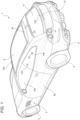
Figure 1 is a perspective view of a motor vehicle according to the invention, -
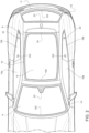
Figure 2 is a plan view of the motor vehicle inFigure 1 , -
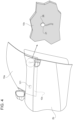
Figures 3 and4 are perspective views, on an enlarged scale and with parts removed for clarity, of a door of the motor vehicle, with the addition of an enlargement of a detailed portion of a window coupled to the door, according to respective variations of the motor vehicle, -
Figure 5 is a block diagram of a noise cancellation algorithm executed by a control unit of the motor vehicle, -
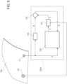
Figure 6 is an alternative variation of the noise cancellation algorithm inFigure 5 , and -
Figure 7 is a side view of the motor vehicle, with parts removed so as to show a passenger compartment inside the motor vehicle. - In
Figure 1 ,reference numeral 1 is used to indicate, as a whole, a motor vehicle. - The
motor vehicle 1 comprises abody 2, in turn including a chassis 3 (Figure 7 ) and abodywork 4 carried by thechassis 3 and defining the outer surfaces of themotor vehicle 1. - Furthermore, the
motor vehicle 1 comprises a plurality ofwheels 5, (only two of which are illustrated inFigure 1 ). Thewheels 5 are coupled to thebody 2 or more precisely to thechassis 3 by means of suspensions of known type and not illustrated. - The
body 2 or more precisely thebodywork 4 comprises a plurality of walls delimiting apassenger compartment 6 of themotor vehicle 1. - The
passenger compartment 6 is illustrated inFigure 6 and is configured to accommodate one or more passengers, among whom adriver 7. - In other words, the
passenger compartment 6 comprises a position (for example comprising a seat for thedriver 7 and a steering wheel of the motor vehicle 1) for accommodating thedriver 7. - More specifically, the walls comprise the windows of the
motor vehicle 1, among which in particular awindshield 9,side windows rear window 11. - In the illustrated embodiment, the
side window 10a is at the front with respect to theside window 10b. In particular, regardless of being more at the front, theside window 10a is coupled to adoor 2b of thebody 2 in a sliding manner on an inner volume of thedoor 2b, with respect to thedoor 2b. - As is visible in
Figures 3 and4 , referring to distinct variations of themotor vehicle 1, theside window 10a has ahidden portion 10c, which is arranged (in particular always) in the inner volume of thedoor 2b, for example regardless of the position of theside window 10a with respect to thedoor 2b. - Furthermore, independently, the
side window 10b is fixed with respect to thebody 2. - The inner volume of the
door 2b is invisible from the outside of themotor vehicle 1. - Furthermore, in the illustrated embodiment, the wall comprising the
rear window 11 comprises more in general ahatchback door 12, in turn comprising therear window 11 and acontour band 13 perimeterally contouring therear window 11, namely contouring at least a portion of the perimeter of therear window 11. In particular, thecontour band 13 extends in a loop all around therear window 11, thereby forming a closed contour. Preferably, but not necessarily, thecontour band 13 is non-transparent or (in particular completely) opaque, whereby, in other words, the view through thecontour band 13 is substantially inhibited, in particular both from the inside of thepassenger compartment 6, and from the outside of themotor vehicle 1. Furthermore, therear window 11 is preferably transparent or has at least a non-zero degree of transparency, at least from the inside of thepassenger compartment 6 or also from the outside of themotor vehicle 1, although not necessarily, because therear window 11 could be opaque both from the inside of thepassenger compartment 6, and from the outside of themotor vehicle 1. Windows are known, in fact, that are opaque from the outside and transparent from the inside or windows are known that are even opaque both from the inside and from the outside. - The latter paragraph can be advantageously extended, although not necessarily, to any one among the walls delimiting the
passenger compartment 6; any one of these walls could in fact comprise a corresponding window like the rear window 11 (since therear window 11 is a type of window, and not with the meaning of identical to the rear window 11) and a contour band like thecontour band 13. The contour band and the window can in general be part of one single body or be made in one single piece, i.e. be seamlessly fixed to each other. - For example, according to the illustrated embodiment, one of the walls delimiting the
passenger compartment 6 comprises thewindshield 9 and arelated contour band 14. - Likewise, although in an independent manner, another one of the walls delimiting the
passenger compartment 6 is or comprises aroof 8 of themotor vehicle 1, which in turn comprises awindow 15 and acontour band 16. - The
contour bands rear window 11, of thewindshield 9, and of theroof 8, respectively with respective looped configurations; however, each one of thecontour bands - More in general, the
roof 8 could comprise or be defined by a sheet, in particular opaque, instead of having thewindow 15. This could be valid, for example, also for the wall comprising therear window 11 or the wall comprising one of theside windows - In general, at least some of the walls delimiting the
passenger compartment 6 have respectiveinner surfaces 17, which directly face thepassenger compartment 6 or, alternatively, are covered with a motor vehicle interior trim layer, for example made of leather, fabric, or plastic material. For example, this aspect, namely having theinner surfaces 17, is valid specifically individually for each one of the walls comprising thewindshield 9, thewindows rear window 11, as well as for theroof 8. More in particular, this aspect, namely having theinner surfaces 17, could be valid also individually for each one of the walls mentioned in this paragraph in the absence of windows, i.e. respectively in the absence of thewindshield 9, thewindows rear window 11, or more precisely when completely opaque, for example as defined by respective sheets. Therefore, this could be valid more specifically also for theroof 8 in the case where it is defined by a sheet. - The walls with the
inner surfaces 17 could have, each one in an independent manner, correspondingouter surfaces 18 directly exposed on the outside of the motor vehicle 1 (possibly considering a finishing paint as part of the outer surfaces 18) and/or, more in particular, could be or be defined, each one in an independent manner, by single panels with respective thicknesses extending respectively from theinner surfaces 17 to corresponding end surfaces opposite theinner surfaces 17 in the direction of the thickness. The end surfaces could for example coincide with the outer surfaces 18 (with the possible finishing paint included), each one in an independent manner. Having theouter surfaces 18 and/or the fact of being defined by single panels, possibly with the end surfaces coinciding with theouter surfaces 18, could be valid also individually for each one of the walls mentioned in this paragraph in the absence of windows, i.e. respectively in the absence of thewindshield 9, thewindows rear window 11, or more precisely when completely opaque, for example as defined by respective sheets. Therefore, this could be valid more specifically also for theroof 8 in the case where it is defined by a sheet. - The
motor vehicle 1 further comprises an active road noise cancelling apparatus, which is configured to reduce or cancel at least part of the noise perceptible from the inside of thepassenger compartment 6 and caused at least in part by the rolling of thewheels 5 on the roadbed during the use of themotor vehicle 1. - The apparatus comprises a plurality of
actuators - The control input signal y can for example be of vector or matrix type, so as to include a plurality of components respectively pertinent for the independent control of the
related actuators related actuators - The
actuators actuators - The
actuators passenger compartment 6 and more in particular having the inner surfaces 17. - The
actuators - In other words, the
actuators - Since the walls communicate with the
passenger compartment 6, the vibrations are indirectly transmitted by the walls to thepassenger compartment 6, where a sound y' is generated by effect of the vibrations of the walls, namely it is produced by means of theactuators - In particular, the
actuators - More precisely, the actuators of electrodynamic type are actuated magnetically, i.e. operate by means of the magnetic induction principle. In practice, the actuators of electrodynamic type include windings immersed in a magnetic field configured so that they produce forces on the walls where the actuators of electrodynamic type are applied when passed through by electric current. The forces are proportional to the intensity of the flow of the magnetic field through the windings and to the intensity of the electric current.
- The actuators of electrodynamic or piezoelectric type are components structurally known per se and available on the market for various functions. In particular, the actuators of electrodynamic or piezoelectric type are also known as (electrodynamic/piezoelectric) shakers.
- The
actuators actuators - In the illustrated embodiment, the
actuators windshield 9, theside windows rear window 11, and theroof 8. - In particular, the
actuators respective contour bands passenger compartment 6. - Alternatively or additionally, each one of the
transducers windshield 9, therear window 11, and the window 15). - For example, the
actuator 122 is arranged and/or applied at thewindow 10b. - The
actuator 121 is preferably arranged and/or applied at the hiddenportion 10c. The same could be valid for theactuator 122, which could be arranged at a similar hidden portion (not illustrated) of thewindow 10b. - Each one of the
actuators Figures 3 ,4 ). - Furthermore, advantageously but not necessarily, the apparatus comprises a plurality of
transducers more transducers transducers - More specifically, each one of the
transducers accelerometer 26 and/or a strain gauge 27. - The detected quantity could actually coincide with an acceleration or a deformation, but not necessarily. In general, in the following, an indicative quantity can coincide with the quantity, although not necessarily. More specifically, the expression "indicative of" can be interpreted as "at least derivable in a direct and univocal manner from", for example by means of one or more pre-established gains or gains variable in a pre-established manner as a function of other detected quantities.
- Referring now to
Figure 5 , theactuators function 101 which associates the control input signal y with the sound y'. - To such regard, it is hereby reminded that the control input signal y is treated as one single signal but it could comprise, in an aggregated form, a plurality of signals configured to control the
respective actuators - Furthermore, the
motor vehicle 1 or the apparatus comprises at least oneerror sensor 32 configured to detect a quantity indicative of a residual sound or error produced by a superposition of the sound y' with an interior noise d inside thepassenger compartment 6 and to generate a related error signal e. - In other words, the
error sensor 32 is configured to detect the residual sound or error. Clearly, the residual sound is inside thepassenger compartment 6. Therefore, theerror sensor 32 is spaced apart towards the inside of thepassenger compartment 6 from theside windows transducers - As is illustrated in the example in
Figure 7 , theerror sensor 32 is arranged inside thepassenger compartment 6, more in particular at the position for thedriver 7, preferably in the upper zone of the position, namely in the zone destined to accommodate the head of thedriver 7 or at a height corresponding to the head of thedriver 7, i.e. at a height of a headrest of the seat of the position. Alternatively or additionally, theerror sensor 32 is arranged inside thepassenger compartment 6 at theroof 8. - In particular, the
error sensor 32 comprises a detector of a sound wave pressure, which herein defines the quantity indicative of the residual sound or error. For example, the detector can be a microphone. - Therefore, the
error sensor 32 is in particular configured to detect the sound wave pressure indicative of the residual sound or error. - Furthermore, the
motor vehicle 1 or the apparatus comprises a control unit ECU configured to execute an active noise cancellation algorithm based on the error signal e, as well as preferably the reference signal x. - The control unit ECU is coupled to the
error sensor 32 for receiving the error signal e, from which the control unit ECU could extract the piece of information about the error. - The control unit ECU is further preferably coupled to each one of the
transducers - The control unit ECU determines through the algorithm the control input signal y, which is adapted to cancel, reduce or minimize the residual sound or the error.
- According to the embodiment in
Figure 5 , the interior noise d corresponds to or is associated with the reference signal x; in other words, the interior noise d is the one caused by the accelerations and/or deformations indicated by the quantities detected by thetransducers - Actually, the accelerations and/or deformations propagate through the
body 2 causing vibrations inside thepassenger compartment 6; the vibrations contribute to the formation of the interior noise d inside thepassenger compartment 6. - Therefore, it is clear that the interior noise d or the error given by the superposition of the interior noise d and the sound y' is defined by sound waves in the
passenger compartment 6. - More precisely, the reference signal x is associated with the interior noise d, which could be considered as a disturbance sound d, according to an
unknown function 102. The sound y', which is suitable or adapted for cancelling the interior noise d, since it corresponds to the control input signal y by means of thefunction 101, superposes the disturbance sound d (sum node 103 inFigure 5 ), thereby forming the residual sound, which can thus be interpreted as the error to be further reduced or cancelled. - The residual sound is thus the effect of the active noise cancellation algorithm on the interior noise d.
- It is thus clear that the interior noise d is different from the accelerations and/or deformations indicated by the quantities detected by the
transducers passenger compartment 6 caused by such accelerations and/or deformations. In fact, as already mentioned, the vibrations contribute to the formation of the interior noise d but they do not necessarily define it. The control unit ECU is configured to control theactuators actuators passenger compartment 6. - The active noise cancellation algorithm can also be considered as a transfer function or a similar linear or non-linear function in the time or frequency domain (function 104 in
Figure 5 ). The algorithm could thus be known per se, for example. - In the specific example in
Figure 5 , the active noise cancellation algorithm comprises an adaptive filter configured to output the control input signal y as a function of the reference signal x and of the error or of the error signal e. - More specifically, the adaptive filter is a parametric function associating the reference signal x with the control input signal y and having variable parameters determined by solving an optimization problem of a cost function or optimization function.
- In particular, the optimization is or comprises a minimization of the cost function, which is specifically an expected value of a squared modulus of the error or of the error signal e.
- Therefore, the adaptive filter is configured as a least mean squares filter.
- Preferably, at least one, some among or more preferably all the
transducers actuators - More specifically, the
transducers - Therefore, implicitly, the accelerations and/or deformations of the walls are associated with the interior noise d or with the error according to an unknown function (just as the reference signal x is associated with the interior noise d according to the function 102). Therefore, the accelerations and/or deformations of the walls are not indicative of the interior noise d and, consequently, in particular of the error.
- In other words, the
transducers - The accelerations can be with respect to the
chassis 3 or more in general with respect to a reference system fixed to themotor vehicle 1, possibly net of the gravity acceleration, such that the related quantities indicative of the accelerations do not substantially take into account the acceleration with which themotor vehicle 1 advances in use or more in general accelerations not having effect on the interior noise d inside thepassenger compartment 6. - Conveniently, each one of the corresponding walls is configured such that a coherence between the reference signal x and the interior noise, i.e. the disturbance sound d, is at least greater than 0.7 and more preferably equal to or greater than 0.8.
- The coherence could, for example, be defined by a function with real values, which could in turn be defined, for example, as the ratio between the squared modulus of the cross-spectral density between the reference signal x and the disturbance sound d and a product between the respective spectral densities of the reference signal x and of the disturbance sound d.
- The coherence is correlated to the
unknown function 102 and can be for example estimated and thus determined by means of suitable experimental tests on themotor vehicle 1. Theunknown function 102 can also possibly be estimated in an experimental manner by using a suitable model. - The coherence can depend for example on the number and on the material of possible layers interposed between the wall and the
passenger compartment 6. The smaller the number of interposed layers, the greater the coherence. - Therefore, in the case where the wall has the
inner surface 17, the coherence will be maximized, especially with the absence of the possible covering with the motor vehicle interior trim layer. - In particular, the maximum coherence is expected when the
transducers - In the illustrated embodiment, the
transducers windshield 9, theside windows rear window 11, and theroof 8. - In particular, the
transducers respective contour bands passenger compartment 6. - Alternatively or additionally, each one of the
transducers windshield 9, therear window 11, and the window 15). Preferably, the latter element is transparent. The transparent element could be an accelerometer, a strain gauge, or any electric member, such as for example a cable. - The element could in particular be a sensible element configured to detect the related quantity.
- For example, the
transducer 22 comprises the transparent element or is entirely transparent and is arranged at thewindow 10b. - The
transducer 21 is preferably arranged at the hiddenportion 10c. The same could apply to thetransducer 22, which could be arranged at the similar hidden portion (not illustrated) of thewindow 10b. - In particular, according to the variation in
Figure 3 , thetransducer 21 comprises an accelerometer fixed to thewindow 10a (in particular at the hiddenportion 10c) by means of a fastening device, in particular a bolt. - According to a variation in
Figure 4 , thetransducer 21 comprises a strain gauge applied to thewindow 10a (in particular at the hiddenportion 10c), for example by means of glueing or by means of integration in thewindow 10a. - More in general, each one of the
transducers Figure 3 ) or by means of glueing to or integration in the wall (for example, when it comprises a strain gauge similar to the variation inFigure 4 ). - The embodiment in
Figure 6 , although conceptually distinct, has some similarities with the embodiment inFigure 5 , therefore it will be described specifying in detail only the differences of the latter. The similar signals will be in particular indicated by the same symbol used inFigure 5 , whereas the similar functions will be indicated by a reference numeral having one hundred more than those inFigure 5 . - In particular, the reference signal x is replaced by an estimate d' of the interior noise d.
- Herein, i.e. in the embodiment in
Figure 6 , the control unit ECU comprises a model (which can be represented for example as a function, in particular a transfer function 205), in particular a mathematical model, for determining the estimate d' of the interior noise d as a function of the control input signal y and of the error signal e. - The model is preferably stored by the control unit ECU and determined experimentally, in particular identified, for example by means of one among the known model identification methods from experimental data, during calibration tests of the
motor vehicle 1. Alternatively or additionally, the model can be updated or determined in real time during the use of themotor vehicle 1 through known learning algorithms, for example based on artificial intelligence, without any loss of generality. The model could also be updatable at the end of a specific utilization session of themotor vehicle 1, in which sufficient data are collected for again identifying the model. - More specifically, the model comprises in turn a primary model (which can be represented for example as a function, in particular a transfer function 206), for example a mathematical primary model, for determining an estimate of the sound y' as a function of the control input signal y. In practice, the primary model simulates or approximates or estimates the operation of the
actuators motor vehicle 1 as if theactuators - Therefore, the model comprises a determination function 207 (represented as a sum node in
Figure 6 ) for determining the estimate d' of the interior noise d from the estimate of the sound y' and from the error signal e, in particular considering that the latter was given by the superposition of the interior noise d with the actual sound y'. In fact, thedetermination function 207 deducts (i.e. in practice subtracts) the estimate of the sound y' from the error signal e, thereby obtaining the estimate d' of the interior noise d. - In particular, the control unit ECU is configured to estimate a sort of reference signal, similar to the embodiment in
Figure 5 , which is defined by the estimate d' by means of the model. Therefore, similar to the embodiment inFigure 5 , the control unit ECU executes the active noise cancellation algorithm with the adaptive filter to output the control input signal y as a function of the estimated reference signal, i.e. in this case of the estimate d', and of the error signal e. - Still more specifically, the control unit ECU obtains the estimate d' for or at a current instant (of time), in particular as a function of the control input signal y and of the error signal e at the current instant. However, the adaptive filter provides the control input signal y for or at a following instant (of time), always as a function of the estimate d' and of the error signal e for the current instant. Furthermore, the adaptive filter corrects the error with a delay of an instant. The latter concept is represented by the
function 208 inFigure 6 , which represents the so-called unitary delay function in the control field. - In the light of the above, the embodiments in
Figure 5 andFigure 6 refer to feedforward and feedback active noise cancelling schemes, respectively. - Clearly, in the embodiment in
Figure 6 , thetransducers - Based on the embodiments in
Figures 5 and6 , it is inferable that more generally, thetransducers - Based on the foregoing, the advantages of the
motor vehicle 1 according to the invention are evident. - The
actuators passenger compartment 6, thereby achieving a high cancellation efficacy of the interior noise d, without any need to increase the number of transducers. Thetransducers - On the other hand, advantageously, the arrangement of the
transducers passenger compartment 6, involves an additional bonus effect in terms of efficacy with respect to the prior art, for example with respect to solutions with the transducers arranged in the proximity of thewheels 5 or of the four corners of themotor vehicle 1. - Finally, it is clear that modifications and variations can be made to the
motor vehicle 1 according to the invention which anyway do not depart from the scope of protection defined by the claims. - In particular, all the mentioned signals can be mono-dimensional or pluri-dimensional, without any loss of generality.
- Furthermore, the number of the described components could vary, as well as the geometrical shape and the dimensions of the described and illustrated components.
- The values indicated within a described interval are to be understood as all described individually, also if not explicitly mentioned in a precise manner.
- The interior noise could also contain components which are not to be attributed only and exclusively to the rolling of the
wheels 5 on the road; but rather, the interior noise could also include components linked to vibrations peculiar of the walls delimiting thepassenger compartment 6 during the utilization of themotor vehicle 1. - Furthermore, the correspondences of the
transducers actuators transducers actuators - Finally, the characteristics of each one of the
transducers actuators transducers actuators
Claims (14)
- Motor vehicle (1) comprising- a body (2) comprising a chassis (3) and a plurality of walls, the walls delimiting a passenger compartment (6) to accommodate one or more passengers (7),- at least one actuator (120, 121, 122, 123, 124) applied to a corresponding wall between said walls and controllable through a control input signal (y) to transmit a vibration corresponding to the control input signal (y) to the corresponding wall, thereby producing a corresponding sound (y') inside the passenger compartment (6),- an error sensor (32) configured to detect a quantity indicative of a residual sound produced by a superposition of said sound (y') with an interior noise (d) inside the passenger compartment (6) and to generate a related error signal (e), and- a control unit (ECU) coupled to the error sensor (32) to receive the error signal (e), configured to execute an active noise cancellation algorithm based on the error signal (e), so as to determine the control input signal (y) adapted to minimize or reduce the residual sound, and further configured to control the actuator (120, 121, 122, 123, 124) with the determined control input signal (y).
- The motor vehicle according to claim 1, wherein the actuator (120, 121, 122, 123, 124) is arranged at the corresponding wall and is configured to transmit the vibration directly to the corresponding wall.
- The motor vehicle according to claim 1 or 2, wherein the corresponding wall has a respective inner surface (17) directly facing the passenger compartment (6) or covered with a motor vehicle interior trim layer.
- The motor vehicle according to claim 3, wherein the corresponding wall has an outer surface (18) directly exposed on the outside of the motor vehicle (1) or covered with a further trim layer, such as a layer of paint, directly exposed on the outside of the motor vehicle.
- The motor vehicle according to claim 4, wherein the corresponding wall is a single panel with a thickness extending from the inner surface (17) to the outer surface (18) .
- The motor vehicle according to any of the preceding claims, wherein the corresponding wall comprises a window (9, 10a, 10b, 11, 15) of the motor vehicle.
- The motor vehicle according to claim 6, wherein the corresponding wall comprises a non-transparent contour band (13, 14, 16) perimeterally contouring the window (9, 10a, 10b, 11, 15) .
- The motor vehicle according to claim 7, wherein the actuator (120, 121, 122, 123, 124) is applied at the contour band (13, 14, 16).
- The motor vehicle according to claim 6, wherein the window (9, 10a, 10b, 11, 15) comprises a hidden portion (10c) arranged within an inner volume of the body (2), the inner volume being invisible from the outside of the motor vehicle (1), wherein the actuator (120, 121, 122, 123, 124) is applied at the hidden portion (10c).
- The motor vehicle according to any one of the preceding claims, further comprising at least one transducer (20, 21, 22, 23, 24) configured to detect a quantity indicative of an acceleration or deformation of a component of the motor vehicle (1) and to generate a related reference signal (x), the control unit (ECU) being coupled to the transducer (20, 21, 22, 23, 24) to receive the reference signal (x), and wherein the active noise cancellation algorithm comprises an adaptive filter (104) configured to output the control input signal (y) as a function of the reference signal (x) and of the error signal (e).
- The motor vehicle according to claim 10, wherein the transducer (20, 21, 22, 23, 24) is coupled to the corresponding wall so as to detect said quantity, whereby the quantity is indicative of the acceleration of the corresponding wall or the deformation of the corresponding wall.
- The motor vehicle according to any one of claims 1 to 9, wherein the control unit (ECU) comprises a model for determining an estimate (d' ) of said interior noise (d) as a function of the control input signal (y) and of the error signal (e) at a current instant, and is configured to estimate a reference signal (x) for the current instant defined by said estimate (d' ) by means of said model, wherein the active noise cancellation algorithm comprises an adaptive filter (204) configured to output the control input signal (y) at an instant following the current instant as a function of the estimated reference signal (x) and of the error signal (e).
- The motor vehicle according to any one of claims 10 to 12, wherein the adaptive filter (104, 204) is a parametric function associating the reference signal (x) with the control input signal (y) and having variable parameters determined by the active noise cancellation algorithm by solving an optimization problem of an optimization function associated with the error signal (e).
- The motor vehicle according to claim 13, wherein the optimization comprises a minimization of the optimization function defining a cost function, the cost function being an expected value of a squared modulus of the error signal (e).
Applications Claiming Priority (1)
| Application Number | Priority Date | Filing Date | Title |
|---|---|---|---|
| IT102023000019644A IT202300019644A1 (en) | 2023-09-25 | 2023-09-25 | MOTOR VEHICLE WITH AN IMPROVED ACTIVE ROAD NOISE CANCELLATION DEVICE |
Publications (1)
| Publication Number | Publication Date |
|---|---|
| EP4528716A1 true EP4528716A1 (en) | 2025-03-26 |
Family
ID=88965311
Family Applications (1)
| Application Number | Title | Priority Date | Filing Date |
|---|---|---|---|
| EP24201876.0A Pending EP4528716A1 (en) | 2023-09-25 | 2024-09-23 | Motor vehicle with improved active road noise cancelling apparatus |
Country Status (3)
| Country | Link |
|---|---|
| US (1) | US20250104683A1 (en) |
| EP (1) | EP4528716A1 (en) |
| IT (1) | IT202300019644A1 (en) |
Citations (3)
| Publication number | Priority date | Publication date | Assignee | Title |
|---|---|---|---|---|
| US5812684A (en) * | 1995-07-05 | 1998-09-22 | Ford Global Technologies, Inc. | Passenger compartment noise attenuation apparatus for use in a motor vehicle |
| US20180130455A1 (en) * | 2016-11-08 | 2018-05-10 | Andersen Corporation | Active noise cancellation systems and methods |
| US20230274725A1 (en) * | 2020-07-28 | 2023-08-31 | Tesla, Inc. | Adaptive noise cancelling system for automotive hands-free telecommunications |
-
2023
- 2023-09-25 IT IT102023000019644A patent/IT202300019644A1/en unknown
-
2024
- 2024-09-03 US US18/822,741 patent/US20250104683A1/en active Pending
- 2024-09-23 EP EP24201876.0A patent/EP4528716A1/en active Pending
Patent Citations (3)
| Publication number | Priority date | Publication date | Assignee | Title |
|---|---|---|---|---|
| US5812684A (en) * | 1995-07-05 | 1998-09-22 | Ford Global Technologies, Inc. | Passenger compartment noise attenuation apparatus for use in a motor vehicle |
| US20180130455A1 (en) * | 2016-11-08 | 2018-05-10 | Andersen Corporation | Active noise cancellation systems and methods |
| US20230274725A1 (en) * | 2020-07-28 | 2023-08-31 | Tesla, Inc. | Adaptive noise cancelling system for automotive hands-free telecommunications |
Also Published As
| Publication number | Publication date |
|---|---|
| IT202300019644A1 (en) | 2025-03-25 |
| US20250104683A1 (en) | 2025-03-27 |
Similar Documents
| Publication | Publication Date | Title |
|---|---|---|
| CN116134512B (en) | Active noise cancellation system based on load factor | |
| EP3244400B1 (en) | Method and system for selecting sensor locations on a vehicle for active road noise control | |
| KR102905999B1 (en) | Active noise cancellation for high-frequency, broadband airborne noise | |
| US5245664A (en) | Active noise control system for automotive vehicle | |
| CN107016987B (en) | Engine noise control | |
| Kim et al. | Active control of road noise considering the vibro-acoustic transfer path of a passenger car | |
| EP4224466B1 (en) | Road noise cancellation shaping filters | |
| EP4528716A1 (en) | Motor vehicle with improved active road noise cancelling apparatus | |
| Dehandschutter et al. | Active control of structure-borne road noise using vibration actuators | |
| JPH07104767A (en) | Vehicle interior noise reduction device | |
| US8184820B2 (en) | Indirect acoustic transfer control of noise | |
| CN110103863A (en) | The vehicle noise of vehicle body installation eliminates system | |
| JPH04113946A (en) | Noise control device for automobile | |
| JP2782937B2 (en) | Active seat device for vehicles | |
| US6150733A (en) | Method and device for influencing an impression which is subjectively perceived by an occupant of a vehicle, in particular of a passenger car, when the vehicle is being operated | |
| JPH03228097A (en) | Vibration controller | |
| IT202300019632A1 (en) | MOTOR VEHICLE WITH AN IMPROVED ACTIVE ROAD NOISE CANCELLATION DEVICE | |
| JPH05265471A (en) | Active noise controller for vehicle | |
| JP2589738Y2 (en) | Vehicle interior noise reduction device | |
| JP2010078852A (en) | Noise control device and noise control method | |
| JPH08292771A (en) | Active noise control device for vehicle | |
| JPH0355465Y2 (en) | ||
| RU2199454C2 (en) | Vehicle | |
| CN116940981A (en) | Apparatus and method for reducing noise in an interior space of a vehicle | |
| Hauer et al. | Interior noise calculation |
Legal Events
| Date | Code | Title | Description |
|---|---|---|---|
| PUAI | Public reference made under article 153(3) epc to a published international application that has entered the european phase |
Free format text: ORIGINAL CODE: 0009012 |
|
| STAA | Information on the status of an ep patent application or granted ep patent |
Free format text: STATUS: THE APPLICATION HAS BEEN PUBLISHED |
|
| AK | Designated contracting states |
Kind code of ref document: A1 Designated state(s): AL AT BE BG CH CY CZ DE DK EE ES FI FR GB GR HR HU IE IS IT LI LT LU LV MC ME MK MT NL NO PL PT RO RS SE SI SK SM TR |
|
| STAA | Information on the status of an ep patent application or granted ep patent |
Free format text: STATUS: REQUEST FOR EXAMINATION WAS MADE |
|
| 17P | Request for examination filed |
Effective date: 20250925 |