EP4528688A1 - Self-driving control system and self-driving control method - Google Patents
Self-driving control system and self-driving control method Download PDFInfo
- Publication number
- EP4528688A1 EP4528688A1 EP23805863.0A EP23805863A EP4528688A1 EP 4528688 A1 EP4528688 A1 EP 4528688A1 EP 23805863 A EP23805863 A EP 23805863A EP 4528688 A1 EP4528688 A1 EP 4528688A1
- Authority
- EP
- European Patent Office
- Prior art keywords
- vehicle
- magnetic
- magnetic field
- marker
- autonomous driving
- Prior art date
- Legal status (The legal status is an assumption and is not a legal conclusion. Google has not performed a legal analysis and makes no representation as to the accuracy of the status listed.)
- Pending
Links
Images











Classifications
-
- G—PHYSICS
- G01—MEASURING; TESTING
- G01R—MEASURING ELECTRIC VARIABLES; MEASURING MAGNETIC VARIABLES
- G01R33/00—Arrangements or instruments for measuring magnetic variables
- G01R33/0094—Sensor arrays
-
- G—PHYSICS
- G05—CONTROLLING; REGULATING
- G05D—SYSTEMS FOR CONTROLLING OR REGULATING NON-ELECTRIC VARIABLES
- G05D1/00—Control of position, course, altitude or attitude of land, water, air or space vehicles, e.g. using automatic pilots
- G05D1/20—Control system inputs
- G05D1/24—Arrangements for determining position or orientation
- G05D1/244—Arrangements for determining position or orientation using passive navigation aids external to the vehicle, e.g. markers, reflectors or magnetic means
- G05D1/2446—Arrangements for determining position or orientation using passive navigation aids external to the vehicle, e.g. markers, reflectors or magnetic means the passive navigation aids having encoded information, e.g. QR codes or ground control points
-
- B—PERFORMING OPERATIONS; TRANSPORTING
- B60—VEHICLES IN GENERAL
- B60W—CONJOINT CONTROL OF VEHICLE SUB-UNITS OF DIFFERENT TYPE OR DIFFERENT FUNCTION; CONTROL SYSTEMS SPECIALLY ADAPTED FOR HYBRID VEHICLES; ROAD VEHICLE DRIVE CONTROL SYSTEMS FOR PURPOSES NOT RELATED TO THE CONTROL OF A PARTICULAR SUB-UNIT
- B60W60/00—Drive control systems specially adapted for autonomous road vehicles
-
- G—PHYSICS
- G01—MEASURING; TESTING
- G01V—GEOPHYSICS; GRAVITATIONAL MEASUREMENTS; DETECTING MASSES OR OBJECTS; TAGS
- G01V3/00—Electric or magnetic prospecting or detecting; Measuring magnetic field characteristics of the earth, e.g. declination, deviation
- G01V3/08—Electric or magnetic prospecting or detecting; Measuring magnetic field characteristics of the earth, e.g. declination, deviation operating with magnetic or electric fields produced or modified by objects or geological structures or by detecting devices
- G01V3/081—Electric or magnetic prospecting or detecting; Measuring magnetic field characteristics of the earth, e.g. declination, deviation operating with magnetic or electric fields produced or modified by objects or geological structures or by detecting devices the magnetic field is produced by the objects or geological structures
-
- G—PHYSICS
- G05—CONTROLLING; REGULATING
- G05D—SYSTEMS FOR CONTROLLING OR REGULATING NON-ELECTRIC VARIABLES
- G05D1/00—Control of position, course, altitude or attitude of land, water, air or space vehicles, e.g. using automatic pilots
- G05D1/20—Control system inputs
- G05D1/24—Arrangements for determining position or orientation
- G05D1/247—Arrangements for determining position or orientation using signals provided by artificial sources external to the vehicle, e.g. navigation beacons
- G05D1/248—Arrangements for determining position or orientation using signals provided by artificial sources external to the vehicle, e.g. navigation beacons generated by satellites, e.g. GPS
-
- G—PHYSICS
- G05—CONTROLLING; REGULATING
- G05D—SYSTEMS FOR CONTROLLING OR REGULATING NON-ELECTRIC VARIABLES
- G05D1/00—Control of position, course, altitude or attitude of land, water, air or space vehicles, e.g. using automatic pilots
- G05D1/60—Intended control result
- G05D1/646—Following a predefined trajectory, e.g. a line marked on the floor or a flight path
-
- G—PHYSICS
- G05—CONTROLLING; REGULATING
- G05D—SYSTEMS FOR CONTROLLING OR REGULATING NON-ELECTRIC VARIABLES
- G05D2105/00—Specific applications of the controlled vehicles
- G05D2105/20—Specific applications of the controlled vehicles for transportation
- G05D2105/22—Specific applications of the controlled vehicles for transportation of humans
-
- G—PHYSICS
- G05—CONTROLLING; REGULATING
- G05D—SYSTEMS FOR CONTROLLING OR REGULATING NON-ELECTRIC VARIABLES
- G05D2107/00—Specific environments of the controlled vehicles
- G05D2107/10—Outdoor regulated spaces
- G05D2107/13—Spaces reserved for vehicle traffic, e.g. roads, regulated airspace or regulated waters
-
- G—PHYSICS
- G05—CONTROLLING; REGULATING
- G05D—SYSTEMS FOR CONTROLLING OR REGULATING NON-ELECTRIC VARIABLES
- G05D2109/00—Types of controlled vehicles
- G05D2109/10—Land vehicles
-
- G—PHYSICS
- G05—CONTROLLING; REGULATING
- G05D—SYSTEMS FOR CONTROLLING OR REGULATING NON-ELECTRIC VARIABLES
- G05D2111/00—Details of signals used for control of position, course, altitude or attitude of land, water, air or space vehicles
- G05D2111/10—Optical signals
- G05D2111/17—Coherent light, e.g. laser signals
-
- G—PHYSICS
- G05—CONTROLLING; REGULATING
- G05D—SYSTEMS FOR CONTROLLING OR REGULATING NON-ELECTRIC VARIABLES
- G05D2111/00—Details of signals used for control of position, course, altitude or attitude of land, water, air or space vehicles
- G05D2111/20—Acoustic signals, e.g. ultrasonic signals
-
- G—PHYSICS
- G05—CONTROLLING; REGULATING
- G05D—SYSTEMS FOR CONTROLLING OR REGULATING NON-ELECTRIC VARIABLES
- G05D2111/00—Details of signals used for control of position, course, altitude or attitude of land, water, air or space vehicles
- G05D2111/30—Radio signals
-
- G—PHYSICS
- G08—SIGNALLING
- G08G—TRAFFIC CONTROL SYSTEMS
- G08G1/00—Traffic control systems for road vehicles
- G08G1/01—Detecting movement of traffic to be counted or controlled
- G08G1/02—Detecting movement of traffic to be counted or controlled using treadles built into the road
Definitions
- the present disclosure relates to an autonomous driving control system and the like for a vehicle that travels on a road provided with markers.
- Patent Literature (PTL) 1 relates to such autonomous driving. More specifically, PTL 1 discloses a vehicle automatic traveling system that travels with automatic steering by detecting magnetic markers laid along the travel path of the vehicle.
- the present disclosure provides an autonomous driving control system and the like that can appropriately control the travel of the vehicle according to the markers.
- An autonomous driving control system is for a vehicle that travels on a road provided with a marker that emits a steady magnetic field or a quasi-steady magnetic field, and includes: a magnetic sensor array that is equipped on the vehicle and senses magnetism; and an information processing circuit that generates an image showing a magnetic field in a region closer to the marker than the magnetic sensor array, according to a sensing result of the magnetism and a fundamental equation of the steady magnetic field and the quasi-steady magnetic field, and controls travel of the vehicle according to the image.
- autonomous driving refers to the automation of driving tasks.
- Autonomous driving capabilities are classified into six levels, ranging from Level 0 to Level 5. Among these levels, Level 5 is also called full autonomous driving. In Level 5, all driving tasks to the destination are performed by the system. This means the driving tasks are not monitored by a human driver. Therefore, there is no room for error in Level 5 implementations.
- LiDAR Light Detection and Ranging
- millimeter-wave radar millimeter-wave radar
- ultrasonic sonar for autonomous driving
- object detection and object recognition are performed by a camera.
- collision avoidance and white line recognition are performed.
- the distance to objects is measured by LiDAR, millimeter-wave radar, and ultrasonic sonar, and collision avoidance is performed.
- AI artificial intelligence
- driving tasks performed by drivers and corresponding images obtained from cameras are learned in advance.
- the same driving task is reproduced by the AI.
- white line recognition is carried out using a camera and AI, and the driving task is reproduced so that the vehicle moves along the white line. This enables the vehicle to move along the road.
- an autonomous driving control system for a vehicle that travels on a road provided with a marker that emits a steady magnetic field or a quasi-steady magnetic field, and includes: a magnetic sensor array that is equipped on the vehicle and senses magnetism; and an information processing circuit that generates an image showing a magnetic field in a region closer to the marker than the magnetic sensor array, according to a sensing result of the magnetism and a fundamental equation of the steady magnetic field and the quasi-steady magnetic field, and controls travel of the vehicle according to the image.
- the autonomous driving control system can sufficiently obtain the spatial change of the magnetic field according to the temporal changes in sensing results and the speed of the vehicle. Therefore, the autonomous driving control system can adequately generate an image showing the magnetic field.
- the magnetic sensor array includes one or more two-dimensional magnetic sensor arrays arranged in a front-rear direction and a left-right direction of the vehicle.
- the autonomous driving control system can sufficiently obtain the spatial change of the magnetic field with a two-dimensional magnetic sensor array. Therefore, the autonomous driving control system can adequately generate an image showing the magnetic field.
- the magnetic sensor array includes one or more one-dimensional magnetic sensor arrays arranged in a left-right direction of the vehicle.
- the magnetic sensor array senses the magnetism in one layer arranged in a front-rear direction and a left-right direction of the vehicle.
- the information processing circuit generates the image according to Equation (5) to be described later which is in accordance with the sensing result and the fundamental equation, where: H i (x, y, z) is an i component in a magnetic field at a coordinate position (x, y, z); i is x, y, or z; z is a coordinate value in a z-direction from a top of the vehicle toward a bottom of the vehicle; x is a coordinate value in an x-direction orthogonal to the z-direction, y is a coordinate value in a y-direction orthogonal to the z-direction and the x-direction, f(k x , k y ) is a two-dimensional Fourier transform image of H i (x, y, 0) indicating the sensing result at (x, y, 0) which is a measurement plane; k x is a wavenumber with respect to x, and k
- the information processing circuit generates the image according to Equation (9) to be described later which is in accordance with the sensing result and the fundamental equation, where: H i (x, y, z) is an i component in a magnetic field at a coordinate position (x, y, z); i is x, y, or z; z is a coordinate value in a z-direction from a top of the vehicle toward a bottom of the vehicle; x is a coordinate value in an x-direction orthogonal to the z-direction, y is a coordinate value in a y-direction orthogonal to the z-direction and the x-direction, f(k x , k y ) is a two-dimensional Fourier transform image of H i (x, y, 0) indicating the sensing result at (x, y, 0) which is a measurement plane; g(k x , k y ) is a two-dimensional
- the autonomous driving control system further includes: at least one of a camera, a LiDAR, a millimeter-wave radar, an ultrasonic sonar, or a GPS receiver equipped on the vehicle.
- the information processing circuit further controls the travel of the vehicle according to the at least one of the camera, the LiDAR, the millimeter-wave radar, the ultrasonic sonar, or the GPS receiver.
- the autonomous driving control system further includes the marker provided on the road.
- the marker includes a plurality of markers provided on the road, and the plurality of markers emit steady magnetic fields or quasi-steady magnetic fields with a plurality of magnetic patterns for controlling the travel of the vehicle.
- each of the plurality of magnetic patterns is a barcode-like magnetic pattern.
- the marker represents a code sequence, as an arrangement of a plurality of magnetic poles, for controlling the travel of the vehicle, the code sequence includes a code for error detection, and the information processing circuit: reads the code sequence according to the image; determines whether the code sequence read includes an error according to the code included in the code sequence read; and controls the travel of the vehicle in accordance with the code sequence read on condition that the code sequence read is determined to include no error.
- the autonomous driving control system can read a code sequence from the marker via an image indicating the magnetic field.
- the autonomous driving control system can determine whether the read-out code sequence includes an error according to the code for error detection. Accordingly, the autonomous driving control system can appropriately control the travel of the vehicle according to a highly reliable code sequence.
- the marker has a wire-like shape.
- the marker is a magnetic material that is magnetic.
- the autonomous driving control system further includes: an induction circuit that is equipped on the vehicle and induces a first magnetic field component.
- the marker emits the steady magnetic field or the quasi-steady magnetic field by inducing a second magnetic field component in response to the first magnetic field component.
- a vehicle includes the autonomous driving control system.
- This image is assumed to show the marker with high accuracy. It is therefore assumed that the marker can be appropriately identified. It therefore becomes possible to appropriately control the travel of the vehicle according to the marker.
- the magnetic field components described in the present disclosure are the components that make up the magnetic field.
- the magnetic field components may be each of several magnetic fields superimposed on the overall magnetic field.
- the devices described in the present disclosure may include a plurality of elements arranged in a distributed manner.
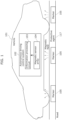
- FIG. 1 is a conceptual diagram illustrating the configuration of the autonomous driving control system according to the present embodiment.
- Vehicle 101 illustrated in FIG. 1 is a machine that travels on a road, and specifically is an automobile. Vehicle 101 can also be referred to as an autonomous driving vehicle.
- Autonomous driving control system 102 is a system that controls the travel of vehicle 101. More specifically, autonomous driving control system 102 controls the travel of vehicle 101 in accordance with markers 105 provided on the road. Controlling travel of vehicle 101 by autonomous driving control system 102 includes, for example, controlling vehicle 101 to travel straight, turn left, turn right, stop, etc.
- Autonomous driving control system 102 includes information processing circuit 103 and magnetic sensor array 104.
- the region closer to marker 105 than magnetic sensor array 104 may specifically be a region closer to the estimated position of marker 105 than magnetic sensor array 104, and may be defined as a position lower than magnetic sensor array 104.
- the region closer to marker 105 than magnetic sensor array 104 may be a region closer to the road surface than magnetic sensor array 104.
- the luminance of the image may correspond to the strength of the magnetic field.
- Information processing circuit 103 controls the travel of vehicle 101 in accordance with the generated image.
- information processing circuit 103 reads out information for controlling vehicle 101 from the generated image. More specifically, information processing circuit 103 reads out information such as travel straight, turn left, turn right, or stop. Information processing circuit 103 then controls the travel of vehicle 101 according to the read-out information.
- Magnetic sensor array 104 is a device that senses magnetism. Magnetic sensor array 104 senses the magnetism of a magnetic field that includes a magnetic field component induced by marker 105 provided on the road. More specifically, for example, magnetic sensor array 104 includes a plurality of magnetic sensors and senses the magnetism of a magnetic field that includes a magnetic field component induced by marker 105 provided on the road with each magnetic sensor.
- Marker 105 induces a magnetic field component. More specifically, marker 105 emits a steady magnetic field or a quasi-steady magnetic field. For example, a plurality of markers 105 are provided along the road. Marker 105 may be referred to as a magnetic marker.
- marker 105 may be a magnetic material (specifically a ferromagnetic material) that is magnetic such as a permanent magnet. Marker 105 embodied as a magnetic material that is magnetic may induce a magnetic field component. Marker 105 may be, for example, an electric conductor that is conductive, such as a ring or coil. Marker 105 embodied as an electric conductor that is conductive may induce a magnetic field component based on electromagnetic induction. This will be described in greater detail later.
- marker 105 may represent a code sequence, as an arrangement of a plurality of magnetic poles, for controlling travel of vehicle 101.
- Information processing circuit 103 may read out a code sequence in accordance with the generated image, and control the travel of vehicle 101 in accordance with the read-out code sequence.
- Information processing circuit 103 may ignore the read-out code sequence if it is determined that the read-out code sequence includes an error. In this case, information processing circuit 103 may output an alert indicating that the read-out code sequence includes an error. Alternatively, in this case, information processing circuit 103 may correct the error and control the travel of vehicle 101 in accordance with the error-corrected code sequence.
- Protective agent 117 covers marker 105 and forms a layer for protecting marker 105.
- a protective film containing a resin or the like may be used as protective agent 117.
- a layer of protective agent 117 may be formed by applying a protective coating to the plurality of markers 105 and the road surface.
- magnetic sensor array 104 of autonomous driving control system 102 senses magnetism (S101).
- information processing circuit 103 of autonomous driving control system 102 generates an image showing the magnetic field in a region closer to marker 105 than magnetic sensor array 104, according to the sensing result of magnetism and the fundamental equation of the steady magnetic field and the quasi-steady magnetic field (S102).
- Information processing circuit 103 controls the travel of vehicle 101 in accordance with the generated image (S103).
- At least one of one or more cameras 106, one or more LiDARs 107, one or more wave sensors 108, and global positioning system (GPS) receiver 109 may be equipped on vehicle 101.
- wave sensor 108 may be a millimeter wave radar, an ultrasonic sonar, or a combination thereof.
- Information processing circuit 103 may perform collision avoidance by controlling the traveling of vehicle 101 according to information obtained from the one or more cameras 106, the one or more LiDARs 107, and the one or more wave sensors 108. In doing so, information processing circuit 103 may perform collision avoidance by performing object detection and object recognition using a neural network.
- control for causing vehicle 101 to travel along a road using markers 105 and control for performing collision avoidance using the one or more cameras 106, the one or more LiDARs 107, and the one or more wave sensors 108 may be combined.
- information processing circuit 103 may obtain position information of vehicle 101 from GPS receiver 109 and control the travel of vehicle 101 according to the position information.
- Autonomous driving control system 102 may include at least one of: the one or more cameras 106; the one or more LiDARs 107; the one or more wave sensors 108; or GPS receiver 109.
- FIG. 4 is side view of vehicle 101 illustrated in FIG. 1 .
- magnetic sensor array 104 is disposed at the lower portion of vehicle 101.
- Magnetic sensor array 104 senses the magnetism of a magnetic field that includes a magnetic field component induced by marker 105.
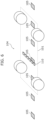
- FIG. 5 is a conceptual diagram illustrating a first example of magnetic sensor array 104 illustrated in FIG. 1 .
- magnetic sensor array 104 is a two-dimensional magnetic sensor array arranged in the front-rear direction and the left-right direction of vehicle 101.
- magnetic sensor array 104 includes a plurality of magnetic sensors 110 arranged in the front-rear direction and the left-right direction of vehicle 101.
- FIG. 6 is a conceptual diagram illustrating a second example of magnetic sensor array 104 illustrated in FIG. 1 .
- magnetic sensor array 104 is a one-dimensional magnetic sensor array arranged in the left-right direction of vehicle 101. Stated differently, magnetic sensor array 104 includes a plurality of magnetic sensors 110 arranged in the left-right direction of vehicle 101.
- FIG. 7 is a conceptual diagram illustrating a first example of the reconstruction according to the present embodiment.
- magnetic sensor array 104 which is a one-dimensional magnetic sensor array, can scan a two-dimensional measurement plane above marker 105. This makes it possible to obtain a sensing result of magnetism on a two-dimensional measurement plane, that is, a two-dimensional sensing result.
- information processing circuit 103 obtains the speed of vehicle 101 from a speedometer or the like of vehicle 101, and converts the temporal changes in the sensing results in magnetic sensor array 104 into spatial changes according to the speed of vehicle 101. More specifically, the higher the speed of vehicle 101 is, the wider the range over which the temporal changes in the sensing results in magnetic sensor array 104 may be converted into spatial changes. This makes it possible to appropriately obtain a two-dimensional sensing result.
- magnetic sensor array 104 which is a two-dimensional magnetic sensor array
- a one-dimensional magnetic sensor array can be considered to exist for each row in the left-right direction. Therefore, according to the above operations, a two-dimensional sensing result is obtained for each row in the left-right direction. This makes it possible to obtain a plurality of two-dimensional sensing results, one for each of the plurality of rows in the left-right direction.
- FIG. 8 is a conceptual diagram illustrating the coordinate system for the reconstruction illustrated in FIG. 7.
- FIG. 8 expresses the measurement plane and the reconstruction plane in an xyz orthogonal coordinate system.
- z is a coordinate value in the z-direction from the top of vehicle 101 toward the bottom
- x is a coordinate value in the x-direction orthogonal to the z-direction
- y is a coordinate value in the y-direction orthogonal to the z-direction and the x-direction.
- the x-direction corresponds to the left-right direction of vehicle 101
- the y-direction corresponds to the front-rear direction of vehicle 101.
- the x-direction corresponds to the front-rear direction of vehicle 101
- the y-direction corresponds to the left-right direction of vehicle 101.
- Equation (1) is x, y, or z.
- Equation (2) is the Laplacian, also called the Laplacian operator.
- Equation (2) A general solution of the above Equation (1) is expressed by the following Equation (2) as the sum of an exponentially increasing term and an exponentially decaying term in the z-direction.
- Equation (5) representing the magnetic field (specifically, the i component of the magnetic field vector) is derived according to the sensing result of the magnetic field and the fundamental equation of the steady magnetic field and the quasi-steady magnetic field.
- f(k x , k y ) is obtained by performing a two-dimensional Fourier transform with respect to x and y on H i (x, y, 0) obtained from the sensing result.
- H i (x, y, z a ) on the reconstruction plane is obtained. This makes it possible to accurately obtain information on the magnetic field in the reconstruction plane.
- H i (x, y, z a ) on the reconstruction plane is expressed as Equation (6) below.
- Information processing circuit 103 may generate an image expressed by H i (x, y, z a ) in the above Equation (6) as the image representing the magnetic field on the reconstruction plane.
- one measurement plane is used, but two measurement planes may be used. This will be described in greater detail below with reference to FIG. 9 through FIG. 12 .
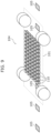
- FIG. 9 is a conceptual diagram illustrating a third example of magnetic sensor array 104 illustrated in FIG. 1 .
- magnetic sensor array 104 is a combination of a first two-dimensional magnetic sensor array and a second two-dimensional magnetic sensor array, each of which is arranged in the front-rear direction and the left-right direction of vehicle 101.
- Each of the first two-dimensional magnetic sensor array and the second two-dimensional magnetic sensor array arranged in the front-rear direction and the left-right direction of vehicle 101 includes a plurality of magnetic sensors 110 arranged in the front-rear direction and the left-right direction of vehicle 101.
- the position of the first two-dimensional magnetic sensor array and the position of the second two-dimensional magnetic sensor array are different from each other in the up-down direction of vehicle 101.
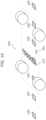
- FIG. 10 is a conceptual diagram illustrating a fourth example of magnetic sensor array 104 illustrated in FIG. 1 .
- magnetic sensor array 104 is a combination of a first one-dimensional magnetic sensor array and a second one-dimensional magnetic sensor array, each of which is arranged in the left-right direction of vehicle 101.
- Each of the first one-dimensional magnetic sensor array and the second one-dimensional magnetic sensor array arranged in the left-right direction of vehicle 101 includes a plurality of magnetic sensors 110 arranged in the left-right direction of vehicle 101.
- the position of the first one-dimensional magnetic sensor array and the position of the second one-dimensional magnetic sensor array are different from each other in the up-down direction of vehicle 101.
- the position of the first one-dimensional magnetic sensor array and the position of the second one-dimensional magnetic sensor array in the front-rear direction of vehicle 101 are different from each other in this example, they may coincide with each other.
- FIG. 11 is a conceptual diagram illustrating a second example of the reconstruction according to the present embodiment.
- magnetic sensor array 104 which is a combination of two one-dimensional magnetic sensor arrays, can scan two measurement planes above marker 105. This makes it possible to obtain a sensing result of magnetism on two measurement planes.
- FIG. 9 as well, it possible to obtain a sensing result of magnetism on two measurement planes.
- the speed of vehicle 101 may be used in the examples of FIG. 9 and FIG. 10 , similar to the examples of FIG. 5 and FIG. 6 .
- Information processing circuit 103 generates an image showing the magnetic field in a reconstruction plane closer to marker 105 than the two measurement planes, according to the sensing result of magnetism in the two measurement planes and the fundamental equation of the steady magnetic field and the quasi-steady magnetic field.
- FIG. 12 is a conceptual diagram illustrating the coordinate system for the reconstruction illustrated in FIG. 11.
- FIG. 12 expresses the two measurement planes and the reconstruction plane in an xyz orthogonal coordinate system.
- z is a coordinate value in the z-direction from the top of vehicle 101 toward the bottom
- x is a coordinate value in the x-direction orthogonal to the z-direction
- y is a coordinate value in the y-direction orthogonal to the z-direction and the x-direction.
- Equation (1) holds true for H i (x, y, z), which is the i-component of the magnetic field vector in the xyz orthogonal coordinate system.
- Equation (2) the general solution of the above Equation (1) is expressed as the above Equation (2).
- the magnetic sources are assumed to be on both the positive side and the negative side in the z-direction.
- z 0 of the i-component of the magnetic field vector.
- a(k x , k y ) and b(k x , k y ) in Equation (2) can be obtained as illustrated in Equation (7) and Equation (8) below, respectively.
- a k x , k y 1 2 f k x , k y + g k x , k y k x 2 + k y 2
- b k x , k y 1 2 f k x , k y ⁇ g k x , k y k x 2 + k y 2
- Equation (9) H i (x, y, z) is obtained as in Equation (9) below.
- Equation (9) representing the magnetic field (specifically, the i component of the magnetic field vector) is derived according to the sensing result of the magnetic field and the fundamental equation of the steady magnetic field and the quasi-steady magnetic field in the free space.
- H i (x, y, 0) which is the Dirichlet-type boundary condition
- z 0 is approximately obtained.
- f(k x , k y ) and g(k x , k y ) are obtained by performing a two-dimensional Fourier transform with respect to x and y on H i (x, y, 0) and ⁇ / ⁇ zH i (x, y, z)
- z 0 obtained from the sensing results.
- H i (x, y, z a ) on the reconstruction plane is obtained. This makes it possible to accurately obtain information on the magnetic field in the reconstruction plane.
- H i (x, y, z a ) on the reconstruction plane is expressed as Equation (10) below.
- Information processing circuit 103 may generate an image expressed by H i (x, y, z a ) in the above Equation (10) as the image representing the magnetic field on the reconstruction plane.
- FIG. 13 is a block diagram illustrating the details of the configuration of autonomous driving control system 102 illustrated in FIG. 1 .
- autonomous driving control system 102 includes magnetic sensor array 104 and information processing circuit 103.
- Autonomous driving control system 102 may further include travel controller 113.
- Travel controller 113 is a device for driving vehicle 101 and includes a power source, actuators, electric circuits, and the like.
- information processing circuit 103 may control the travel of vehicle 101 via travel controller 113 by transmitting a control signal for controlling the travel of vehicle 101 to travel controller 113.
- Magnetic sensor array 104 includes a plurality of magnetic sensors 110.
- Information processing circuit 103 includes input circuit 111 and arithmetic circuit 112.
- Input circuit 111 is an electric circuit for obtaining information and inputting information to arithmetic circuit 112. For example, input circuit 111 obtains a sensing result of magnetism from magnetic sensor array 104. More specifically, input circuit 111 obtains a sensing result of magnetism from each magnetic sensor 110 included in magnetic sensor array 104. Input circuit 111 inputs the sensing result of magnetism to arithmetic circuit 112.
- Input circuit 111 may perform AD conversion (analog-to-digital conversion). For example, input circuit 111 may obtain a sensing result of magnetism from magnetic sensor array 104 as an analog signal. Input circuit 111 may convert the sensing result obtained as an analog signal into a digital signal. Input circuit 111 may input the sensing result converted into a digital signal to arithmetic circuit 112.
- AD conversion analog-to-digital conversion
- FIG. 14 is conceptual diagram illustrating marker 105, a measurement image, and a reconstruction image according to the present embodiment.
- Marker 105 includes a plurality of magnetic poles comprising one or more N poles and one or more S poles.
- Magnetic sensor array 104 senses the magnetism of a magnetic field that includes a magnetic field component induced by marker 105. The sensing result is obtained as a measurement image.
- FIG. 15 is a conceptual diagram illustrating a first example of marker 105.
- the black portion is the N pole portion of marker 105.
- the white portion is the portion of marker 105 other than the N pole. Stated differently, the white portion is the S pole portion of marker 105, or the portion of marker 105 that is neither the N pole nor the S pole. "N pole" and "S pole” may be switched in this description.
- FIG. 16 is a conceptual diagram illustrating a second example of marker 105.
- the black portion is the N pole portion of marker 105
- the white portion is the portion of marker 105 other than the N pole.
- N pole and S pole may be switched in this description.
- marker 105 may indicate 4 types of control-travel straight, turn right, turn left, and stop-using 2 bits.
- One bit may be expressed by one section of the N pole or S pole in marker 105.
- noise may be generated by, for example, manholes and fallen objects. Therefore, marker 105 may represent these controls using a greater number of bits.
- the magnetic field component induced by marker 105 diffuses and the contrast of the measurement image decreases. This may result in the reconstruction image not being appropriately obtained.
- the plurality of markers 105 should be arranged at intervals shorter than the length of vehicle 101 in the front-rear direction of vehicle 101 (for example, 5 m).
- FIG. 20 is a conceptual diagram illustrating a fourth example of marker 105.
- a concentric marker 105 is used.
- marker 105 includes concentric magnetic poles.
- magnetic wires are arranged in circular shapes with radii of 5 cm, 10 cm, and 15 cm, and are fixed by a support member.
- positions where a magnetic wire can be arranged are defined as K, L, and M.
- the magnetic pattern of marker 105 is determined by where among K, L, and M the magnetic wires are actually arranged.
- a magnetic wire may be arranged in one of K, L, or M, may be arranged in two of them, or may be arranged in all three. Stated differently, the possible magnetic wire arrangements are K, L, M, KL, KM, LM, and KLM. In this way, seven magnetic patterns can be used.
- FIG. 21 is a conceptual diagram illustrating the magnetic field direction around concentric marker 105.
- the magnetic wires are arranged such that the magnetic field direction is oriented upward from marker 105. More specifically, the magnetic wire is arranged such that the N pole is positioned on the upper side.
- the magnetic wire may be arranged such that the S pole is positioned on the upper side, or arranged such that the S pole is on the inner side and the N pole is on the outer side, or arranged such that the N pole is on the inner side and the S pole is on the outer side.
- the magnetic pattern becomes more easily identifiable if the orientation of K, L, and M is consistent such that one of the N pole or S pole is positioned on the upper side for all of them.
- FIG. 22 shows reconstruction images in a case where concentric marker 105 is used.
- Reconstruction images such as those illustrated in FIG. 22 are generated by information processing circuit 103 for each of the following magnetic wire arrangements: K, L, M, KL, KM, LM, and KLM.
- the white portion corresponds to the N pole
- the black portion corresponds to the S pole.
- information processing circuit 103 can appropriately identify the magnetic pattern based on the reconstruction image, and can appropriately control the travel of vehicle 101 based on the magnetic pattern.
- Information processing circuit 103 can appropriately identify the magnetic pattern regardless of the orientation of vehicle 101, and can appropriately read control information such as turn right, turn left, or travel straight indicated by the magnetic pattern.
- three circles are used, but two or fewer circles may be used, or four or more circles may be used.
- the number of circles determines the number of magnetic patterns and the number of types of control.
- FIG. 23 is a conceptual diagram illustrating a fifth example of marker 105.
- an electric conductor is used as marker 105.
- the electric conductor used as marker 105 is a closed circuit of a metal such as copper.
- An annular (ring-shaped) electric conductor may be used as marker 105, or a coil-shaped electric conductor may be used as marker 105.
- Marker 105 which is an electric conductor, induces a magnetic field component by electromagnetic induction.
- Vehicle 101 is equipped with an induction circuit for generating electromagnetic induction.
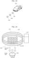
- FIG. 24 is a conceptual diagram illustrating the induction circuit equipped on vehicle 101.
- induction circuit 114 equipped on vehicle 101 may be a coil connected to power source 115.
- Induction circuit 114 equipped on vehicle 101 may include power source 115.
- Induction circuit 114 may be arranged to cover magnetic sensor array 104 that includes the plurality of magnetic sensors 110.
- induction circuit 114 by current flowing in induction circuit 114, induction circuit 114 induces a downward first magnetic field component underneath vehicle 101.
- electromagnetic induction occurs, current flows in marker 105, which is an electric conductor, and marker 105 induces an upward second magnetic field component.
- Magnetic sensor array 104 senses the magnetism of the magnetic field that includes the second magnetic field component.
- Autonomous driving control system 102 can sense the magnetism of the magnetic field including the magnetic field component induced by marker 105.
- Autonomous driving control system 102 can generate an image showing the magnetic field in a region close to marker 105, and appropriately control the travel of vehicle 101 according to the image.
- the magnetic poles of permanent magnets such as ferrite magnets may be altered by a strong external magnetic field.
- marker 105 is a permanent magnet such as a ferrite magnet
- the magnetic pattern may be altered by a strong external magnetic field.
- marker 105 is an electric conductor such as copper, magnetism is appropriately controlled by electromagnetic induction, thereby inhibiting adverse effects such as changes in the magnetic pattern.
- marker 105 which is an electric conductor, has a magnetic pattern corresponding to the shape of the electric conductor.
- the plurality of markers 105 may emit steady magnetic fields or quasi-steady magnetic fields with a plurality of magnetic patterns by having a plurality of shapes.
- information processing circuit 103 of autonomous driving control system 102 may switch between an operation corresponding to an electric conductor and an operation corresponding to a permanent magnet by switching whether or not to apply current to induction circuit 114.
- FIG. 25 is a conceptual diagram illustrating another example of the electric conductor used as marker 105.
- the electric conductor used as marker 105 is not limited to an annular electric conductor, and may be a metal disc or the like. Even when the electric conductor is a metal disc, eddy currents are generated within the metal disc by electromagnetic induction. As a result, a magnetic field component is induced.
- a downward first magnetic field component is induced by current flowing in induction circuit 114 of vehicle 101.
- electromagnetic induction occurs, eddy currents flow in the metal disc, and the metal disc induces an upward second magnetic field component.
- Magnetic sensor array 104 senses the magnetism of the magnetic field that includes the second magnetic field component. This enables autonomous driving control system 102 to sense the magnetism of the magnetic field including the magnetic field component induced by the metal disc installed as marker 105.
- FIG. 26 is a conceptual diagram illustrating yet another example of the electric conductor used as marker 105.
- the electric conductor used as marker 105 may be a coil-shaped closed circuit. Note that the electric conductor used as marker 105 does not need to be connected to a power source, nor does it need to include a power source.
- an electric conductor that is conductive may be used instead of a magnetic material that is magnetic.
- FIG. 28 is a conceptual diagram schematically illustrating an example of the electric conductor corresponding to the example in FIG. 16 .
- a closed circuit of an electric conductor as illustrated in FIG. 28 may be arranged along the outline of the black portion (or white portion).
- FIG. 30 is a conceptual diagram schematically illustrating another example of the electric conductor corresponding to the example in FIG. 16 .
- a plate of an electric conductor may be arranged in the black portion (or white portion) as illustrated in FIG. 30 .
- a plate-shaped electric conductor instead of an annular electric conductor as illustrated in FIG. 28 , a plate-shaped electric conductor may be used.
- eddy currents are generated in the electric conductor by electromagnetic induction, and a magnetic field component is induced from the electric conductor.
- a two-dimensional code-like magnetic pattern is formed.
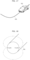
- a wire-shaped electric conductor may be used instead of the magnetic wire illustrated in FIG. 17 through FIG. 19 . In this case as well, the control and other aspects explained in FIG. 17 through FIG. 19 can be applied.
- a concentric electric conductor may be used instead of the concentric magnetic material that is magnetic illustrated in FIG. 20 through FIG. 22 . In this case as well, the control and other aspects explained in FIG. 20 through FIG. 22 can be applied.
- FIG. 32 is a conceptual diagram illustrating a second specific example of magnetic sensor array 104 illustrated in FIG. 1 .
- the plurality of magnetic sensors 110 of magnetic sensor array 104 are disposed on two planes that are parallel to both the front-rear direction and the left-right direction of vehicle 101, and correspond to two different positions in the up-down direction of vehicle 101.
- a plurality of magnetic sensors 110 are arranged alternately on two planes with respect to each of the front-rear direction and the left-right direction of vehicle 101.
- the displacement in the front-rear direction and left-right direction of the plurality of magnetic sensors 110 disposed on the two planes may be ignored.
- the sensing results may be interpolated by linear interpolation or the like in the front-rear direction and the left-right direction.
- magnetism may be sensed at corresponding positions across two measurement planes, both in the front-rear and left-right directions by magnetic sensor array 104 moving as vehicle 101 moves.
- the displacement in the front-rear direction of the plurality of magnetic sensors 110 disposed on the two planes may be ignored.
- the sensing results may be interpolated by linear interpolation or the like in the front-rear direction.
- magnetism may be sensed at corresponding positions across two measurement planes, both in the front-rear and left-right directions by magnetic sensor array 104 moving as vehicle 101 moves.
- a plurality of magnetic sensors 110 are arranged alternately on two planes with respect to the front-rear direction of vehicle 101, but a plurality of magnetic sensors 110 may be arranged alternately on two planes with respect to the left-right direction of vehicle 101.
- the displacement in the left-right direction of the plurality of magnetic sensors 110 disposed on the two planes may be ignored.
- the sensing results may be interpolated by linear interpolation or the like in the left-right direction.
- FIG. 34 is a conceptual diagram illustrating a fourth specific example of magnetic sensor array 104 illustrated in FIG. 1 .
- the plurality of magnetic sensors 110 of magnetic sensor array 104 are disposed on one plane that is parallel to both the front-rear direction and the left-right direction of vehicle 101. More specifically, in this example, one two-dimensional magnetic sensor array is used. This makes it possible to obtain a sensing result of magnetism on a single planar measurement plane.
- magnetic sensor array 104 in this example may sense magnetism in two measurement planes by vibrating in the up-down direction of vehicle 101.
- An actuator for vibrating magnetic sensor array 104 in the up-down direction of vehicle 101 may be equipped on vehicle 101.
- Autonomous driving control system 102 may include such an actuator.
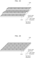
- FIG. 35 is a conceptual diagram illustrating a fifth specific example of magnetic sensor array 104 illustrated in FIG. 1 .
- the plurality of magnetic sensors 110 of magnetic sensor array 104 are disposed on two straight lines that are parallel to the left-right direction of vehicle 101 and correspond to two different positions in the up-down direction of vehicle 101.
- the two straight lines on which the plurality of magnetic sensors 110 are disposed correspond to the same single position in the front-rear direction of vehicle 101. More specifically, two one-dimensional magnetic sensor arrays are stacked.
- the plurality of magnetic sensors 110 also move. This makes it possible to obtain a sensing result of magnetism on two measurement planes corresponding to two different positions in the up-down direction of vehicle 101.
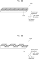
- FIG. 36 is a conceptual diagram illustrating a sixth specific example of magnetic sensor array 104 illustrated in FIG. 1 .
- the plurality of magnetic sensors 110 of magnetic sensor array 104 are disposed on two straight lines that are parallel to the left-right direction of vehicle 101 and correspond to two different positions in the up-down direction of vehicle 101.
- the two straight lines on which the plurality of magnetic sensors 110 are disposed correspond to the same single position in the front-rear direction of vehicle 101.
- a plurality of magnetic sensors 110 are arranged alternately on two straight lines with respect to the left-right direction of vehicle 101. As vehicle 101 moves in the front-rear direction, the plurality of magnetic sensors 110 also move. This makes it possible to obtain a sensing result of magnetism on two measurement planes corresponding to two different positions in the up-down direction of vehicle 101.
- the displacement in the left-right direction of the plurality of magnetic sensors 110 disposed on the two straight lines may be ignored.
- the sensing results may be interpolated by linear interpolation or the like in the left-right direction.
- FIG. 37 is a conceptual diagram illustrating a seventh specific example of magnetic sensor array 104 illustrated in FIG. 1 .
- the plurality of magnetic sensors 110 of magnetic sensor array 104 are disposed on two straight lines that are parallel to the left-right direction of vehicle 101 and correspond to two different positions in the up-down direction of vehicle 101.
- the two straight lines on which the plurality of magnetic sensors 110 are disposed correspond to two different positions in the front-rear direction of vehicle 101.
- the plurality of magnetic sensors 110 also move. This makes it possible to obtain a sensing result of magnetism on two measurement planes corresponding to two different positions in the up-down direction of vehicle 101.
- the displacement in the front-rear direction of the plurality of magnetic sensors 110 disposed on the two straight lines may be ignored.
- magnetism may be sensed at corresponding positions across two measurement planes, both in the front-rear and left-right direction by magnetic sensor array 104 moving as vehicle 101 moves.
- FIG. 38 is a conceptual diagram illustrating an eighth specific example of magnetic sensor array 104 illustrated in FIG. 1 .
- the plurality of magnetic sensors 110 of magnetic sensor array 104 are disposed on one straight line that is parallel to the left-right direction of vehicle 101. More specifically, in this example, one one-dimensional magnetic sensor array is used. As vehicle 101 moves in the front-rear direction, the plurality of magnetic sensors 110 also move. This makes it possible to obtain a sensing result of magnetism on one measurement plane corresponding to one position in the up-down direction of vehicle 101.
- magnetic sensor array 104 in this example may sense magnetism in two measurement planes by vibrating in the up-down direction of vehicle 101.
- An actuator for vibrating magnetic sensor array 104 in the up-down direction of vehicle 101 may be equipped on vehicle 101.
- Autonomous driving control system 102 may include such an actuator.
- the up-down direction in each figure corresponds to the up-down direction of vehicle 101, but the up-down direction may be inverted so that magnetic sensor 110 is installed facing downward.
- a plurality of magnetic sensors 110 are schematically illustrated, but the configuration of the plurality of magnetic sensors 110 is not limited to the examples illustrated in FIG. 31 through FIG. 38 .
- the number of the plurality of magnetic sensors 110 is not limited to the number illustrated in FIG. 31 through FIG. 38 .
- Each magnetic sensor array 104 illustrated in FIG. 31 through FIG. 33 may be considered as a combination of two two-dimensional magnetic sensor arrays arranged in the front-rear direction and the left-right direction of vehicle 101. These two two-dimensional magnetic sensor arrays are disposed at two different positions from each other in the up-down direction of vehicle 101.
- Each magnetic sensor array 104 illustrated in FIG. 35 through FIG. 37 may be considered as a combination of two one-dimensional magnetic sensor arrays arranged in the left-right direction of vehicle 101. These two one-dimensional magnetic sensor arrays are disposed at two different positions from each other in the up-down direction of vehicle 101.
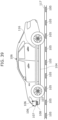
- FIG. 39 is a conceptual diagram illustrating a magnetic shield equipped on vehicle 101.
- information processing circuit 103 generates the reconstruction image using the above-mentioned Equation (5).
- the reconstruction image may not be appropriately generated due to a magnetic noise source above magnetic sensor array 104.
- magnetic shield 116 may be provided above magnetic sensor array 104.
- magnetic shield 116 is made of permalloy, which has a high magnetic permeability.
- Magnetic shield 116 makes it difficult for magnetism to reach magnetic sensor array 104, which is below magnetic shield 116, from a magnetic noise source above magnetic shield 116. This enables the reconstruction image to be appropriately generated even when a magnetic noise source exists above magnetic sensor array 104.
- Magnetic shield 116 is particularly effective in cases in which magnetic sensor array 104 does not sense magnetism in the two measurement planes but senses magnetism in one measurement plane. However, magnetic shield 116 may be used even in cases where magnetic sensor array 104 senses magnetism in the two measurement planes. Autonomous driving control system 102 may include such magnetic shield 116.
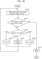
- FIG. 40 is a flowchart illustrating the travel control process performed by information processing circuit 103.
- information processing circuit 103 reads a sensing result of magnetism from magnetic sensor array 104 (S201).
- information processing circuit 103 generates a reconstruction image in a region close to the estimated position of marker 105, according to the sensing result of magnetism and the fundamental equation of the steady magnetic field and the quasi-steady magnetic field. Information processing circuit 103 then performs correlation between the magnetic patterns prepared in memory and the reconstruction image, and determines whether the correlation value is greater than or equal to a threshold value (S202). If the correlation value is less than the threshold value (No in S202), it is assumed that the magnetism of marker 105 has not been sensed. In such cases, information processing circuit 103 stops vehicle 101 (S207).
- information processing circuit 103 determines where the position corresponding to the correlation value greater than or equal to the threshold value is (S203). Stated differently, information processing circuit 103 determines where the position of the portion in the reconstruction image that yields a correlation value greater than or equal to the threshold value is with respect to the magnetic pattern prepared in memory.
- information processing circuit 103 causes vehicle 101 to turn left (S204). If the position corresponding to the correlation value greater than or equal to the threshold value is the center position, information processing circuit 103 causes vehicle 101 to travel straight (S205). If the position corresponding to the correlation value greater than or equal to the threshold value is the right position, information processing circuit 103 causes vehicle 101 to turn right (S206).
- Information processing circuit 103 repeats the above-described processing (i.e., the processing from S201 to S207). This enables information processing circuit 103 to control the travel of vehicle 101 according to the reconstruction image.
- the sensing result may be read in advance in a steady magnetic field or a quasi-steady magnetic field.
- a difference from the sensing result of magnetism in the steady magnetic field may be used. With this, the effects of individual differences among the plurality of magnetic sensors 110 and the effects of environmental magnetic fields can be inhibited.
- Information processing circuit 103 may control the curvature for causing vehicle 101 to turn left or right according to the position corresponding to the correlation value greater than or equal to the threshold value. For example, information processing circuit 103 may increase the curvature as the position corresponding to the correlation value greater than or equal to the threshold value deviates further from the center. This enables information processing circuit 103 to drive vehicle 101 along various curves.
- Information processing circuit 103 may control the travel of vehicle 101 via P control (proportional control). Information processing circuit 103 may use I control (integral control) in curves to drive vehicle 101 smoothly along the curves.
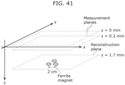
- FIG. 41 is a conceptual diagram of a basic experiment (an experiment with a reduced scale).
- FIG. 41 expresses two measurement planes and a reconstruction plane in an xyz orthogonal coordinate system.
- z is a coordinate value in the z-direction from the measurement planes toward the magnetic source
- x is a coordinate value in the x-direction orthogonal to the z-direction
- y is a coordinate value in the y-direction orthogonal to the z-direction and the x-direction.
- the magnetic source includes three ferrite magnets arranged at 2 cm intervals.
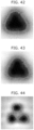
- This verification is a comparative verification between control based on the measurement image and control based on the reconstruction image.
- FIG. 45 is a conceptual diagram illustrating the relationship between a measurement image and a reconstruction image for verification. More specifically, FIG. 45 illustrates the magnetic field distribution on the surface of marker 105, the measurement image showing the sensing result of magnetism in magnetic sensor array 104, and the reconstruction image obtained as an image showing the magnetic field in a region close to marker 105 generated by information processing circuit 103.
- the measurement image corresponds to the sensing result of magnetism in magnetic sensor array 104 spaced from marker 105, and therefore deviates from the magnetic field distribution on the surface of marker 105.
- the reconstruction image is an image obtained according to fundamental equation of steady magnetic fields and quasi-steady magnetic fields, and shows the magnetic field in a region close to marker 105 on the road where marker 105 is provided. Therefore, it approximates the magnetic field distribution on the surface of marker 105. Stated differently, the reconstruction image appropriately shows the magnetic pattern of marker 105.
- autonomous driving control system 102 can more appropriately control the travel of vehicle 101 by using the reconstruction image rather than using the measurement image.
- a prototype model of vehicle 101 equipped with autonomous driving control system 102, and a plurality of markers 105 are used in an indoor environment.
- a plurality of tracking target markers, each being marker 105 implemented as a tracking target, and a plurality of dummy markers, each being marker 105 implemented as a dummy marker are arranged.
- vehicle 101 For both control based on the measurement image and control based on the reconstruction image, it is verified whether vehicle 101 can continuously track only the plurality of tracking target markers among the plurality of markers 105.
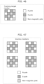
- FIG. 46 is a conceptual diagram illustrating a tracking target marker.
- the tracking target marker has a two-dimensional code-like magnetic pattern. Stated differently, the tracking target marker has a matrix-like magnetic pattern, and each of the plurality of sections included in the magnetic pattern corresponds to an N pole, an S pole, or a non-magnetic pole that is neither an N pole nor an S pole.
- FIG. 47 is a conceptual diagram illustrating dummy markers. As illustrated in FIG. 47 , four types of dummy markers are used for verification.
- the dummy marker similar to the tracking target marker, has a matrix-like magnetic pattern, and each of the plurality of sections included in the magnetic pattern corresponds to an N pole, an S pole, or a non-magnetic pole.
- the four types of dummy markers have four mutually different types of magnetic patterns.
- the four types of magnetic patterns of the four types of dummy markers are also different from the magnetic pattern of the tracking target marker.
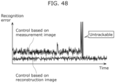
- FIG. 48 is a graph illustrating comparative verification results between control based on the measurement image and control based on the reconstruction image.
- the recognition error is the difference between the position of the tracking target marker recognized by autonomous driving control system 102 and the actual position of the tracking target marker.
- the recognition error is relatively large, and vehicle 101 becomes unable to track the tracking target marker partway through.
- the recognition error is relatively small, and vehicle 101 is able to continuously track the tracking target marker until the end.
- autonomous driving control system 102 can more appropriately control the travel of vehicle 101 by using the reconstruction image rather than using the measurement image.
- autonomous driving control system 102 of vehicle 101 that travels on road provided with markers 105 includes magnetic sensor array 104 and information processing circuit 103.
- Magnetic sensor array 104 is equipped on vehicle 101 and senses magnetism.
- Information processing circuit 103 generates an image showing the magnetic field in a region closer to marker 105 than magnetic sensor array 104, according to the sensing result of magnetism and the fundamental equation of the steady magnetic field and the quasi-steady magnetic field.
- Information processing circuit 103 controls the travel of vehicle 101 in accordance with the image.
- This image is assumed to show marker 105 with high accuracy. It is therefore assumed that marker 105 can be appropriately identified. Therefore, autonomous driving control system 102 can appropriately control the travel of vehicle 101 according to marker 105.
- information processing circuit 103 may obtain the speed of vehicle 101.
- Information processing circuit 103 may convert temporal changes in the sensing result into spatial changes according to the speed.
- Information processing circuit 103 may generate an image showing the magnetic field according to the fundamental equation and the sensing result in which the temporal changes have been converted into the spatial changes.
- magnetic sensor array 104 may include one or more two-dimensional magnetic sensor arrays arranged in the front-rear direction and the left-right direction of vehicle 101. Accordingly, autonomous driving control system 102 can sufficiently obtain the spatial change of the magnetic field with a two-dimensional magnetic sensor array. Therefore, autonomous driving control system 102 can adequately generate an image showing the magnetic field.
- magnetic sensor array 104 may include one or more one-dimensional magnetic sensor arrays arranged in the left-right direction of vehicle 101. This enables autonomous driving control system 102 to appropriately control the travel of vehicle 101 with few resources and at low cost.
- magnetic sensor array 104 may sense magnetism in one layer arranged in the front-rear direction and the left-right direction of vehicle 101. This enables autonomous driving control system 102 to sense magnetism in a simple manner and perform processing with a low computational load.
- magnetic sensor array 104 may sense magnetism in two layers arranged in the front-rear direction and the left-right direction of vehicle 101. This enables autonomous driving control system 102 to appropriately obtain the gradient of the magnetic field in the up-down direction and adequately generate an image showing the magnetic field.
- information processing circuit 103 may generate the image according to the above Equation (5) as an arithmetic expression which is in accordance with the sensing result and the fundamental equation.
- H i (x, y, z) represents the i component of the magnetic field at coordinate position (x, y, z).
- i indicates x, y, or z.
- z is a coordinate value in the z-direction from the top of vehicle 101 toward bottom.
- x is a coordinate value in the x-direction orthogonal to the z-direction.
- y is a coordinate value in the y-direction orthogonal to the z-direction and the x-direction.
- f(k x , k y ) represents the two-dimensional Fourier transform image of H i (x, y, 0).
- H i (x, y, 0) represents the sensing result at the measurement plane (x, y, 0).
- k x is a wavenumber with respect to x.
- k y is a wavenumber with respect to y.
- information processing circuit 103 may generate the image according to the above Equation (9) as an arithmetic expression which is in accordance with the sensing result and the fundamental equation.
- H i (x, y, z) represents the i component of the magnetic field at coordinate position (x, y, z).
- i indicates x, y, or z.
- z is a coordinate value in the z-direction from the top of vehicle 101 toward bottom.
- x is a coordinate value in the x-direction orthogonal to the z-direction.
- y is a coordinate value in the y-direction orthogonal to the z-direction and the x-direction.
- f(k x , k y ) represents the two-dimensional Fourier transform image of H i (x, y, 0).
- H i (x, y, 0) represents the sensing result at the measurement plane (x, y, 0).
- g(k x , k y ) represents the two-dimensional Fourier transform image of ⁇ / ⁇ zH i (x, y, z)
- z 0.
- k x is a wavenumber with respect to x.
- k y is a wavenumber with respect to y.
- autonomous driving control system 102 may further include at least one of a camera, a LiDAR, a millimeter-wave radar, an ultrasonic sonar, or a GPS receiver.
- the at least one of the camera, the LiDAR, the millimeter-wave radar, the ultrasonic sonar, or the GPS receiver is equipped on vehicle 101.
- Information processing circuit 103 may further control the travel of vehicle 101 according to the at least one of the camera, the LiDAR, the millimeter-wave radar, the ultrasonic sonar, or the GPS receiver.
- Autonomous driving control system 102 may further include, for example, marker 105 provided on the road. This enables autonomous driving control system 102 to control the travel of vehicle 101 according to marker 105 included in autonomous driving control system 102.
- Autonomous driving control system 102 may further include, for example, a plurality of markers 105 each provided on the road as marker 105.
- the plurality of markers 105 may emit steady magnetic fields or quasi-steady magnetic fields with a plurality of magnetic patterns for controlling the travel of vehicle 101. This enables autonomous driving control system 102 to control the travel of vehicle 101 according to a plurality of magnetic patterns.
- each of the plurality of magnetic patterns may be a concentric magnetic pattern. This enables autonomous driving control system 102 to inhibit the influence of the orientation of vehicle 101 in the identification of magnetic patterns.
- each of the plurality of magnetic patterns may be a barcode-like magnetic pattern. This enables autonomous driving control system 102 to control the travel of vehicle 101 according to a barcode that can simply indicate various information.
- each of the plurality of magnetic patterns may be a two-dimensional code-like magnetic pattern. This enables autonomous driving control system 102 to control the travel of vehicle 101 according to a two-dimensional code that can indicate a greater variety of information.
- marker 105 may represent a code sequence, as an arrangement of a plurality of magnetic poles, for controlling travel of vehicle 101.
- the code sequence may include a code for error detection.
- Information processing circuit 103 may read out the code sequence in accordance with the image showing the magnetic field.
- information processing circuit 103 may determine whether the read-out code sequence includes an error according to the code included in the read-out code sequence. Information processing circuit 103 may control the travel of vehicle 101 in accordance with the read-out code sequence if it is determined that no error is included in the read-out code sequence.
- autonomous driving control system 102 can read a code sequence from marker 105 via an image indicating the magnetic field.
- Autonomous driving control system 102 can determine whether the read-out code sequence includes an error according to the code for error detection. Accordingly, autonomous driving control system 102 can appropriately control the travel of vehicle 101 according to a highly reliable code sequence.
- marker 105 may have a wire-like shape. This enables autonomous driving control system 102 to control the travel of vehicle 101 along a wire-like shape.
- marker 105 may be a magnetic material that is magnetic. This enables autonomous driving control system 102 to control the travel of vehicle 101 using a simple marker 105.
- vehicle 101 may include autonomous driving control system 102. This enables vehicle 101 to control the travel of vehicle 101 according to an image showing the magnetic field in a region closer to marker 105 than magnetic sensor array 104.
- processing that is executed by a specific element according to the embodiment may be executed by a different element, instead of the specific element.
- a sequence of a plurality of processes may be changed, or a plurality of processes may be executed in parallel.
- a plurality of variations may also be applied in combination.
- the ordinal numbers used in the description, such as first, second, etc., may be replaced as appropriate. The ordinal number may be given anew to or removed from element names, etc.
- Each element of the autonomous driving control system may be an electric circuit. These electric circuits may be configured collectively as a single electric circuit, or configured individually as different electric circuits. These electric circuits may correspond to dedicated hardware or general-purpose hardware that executes the above-described program or the like.
Landscapes
- Engineering & Computer Science (AREA)
- Physics & Mathematics (AREA)
- Remote Sensing (AREA)
- General Physics & Mathematics (AREA)
- Automation & Control Theory (AREA)
- Aviation & Aerospace Engineering (AREA)
- Radar, Positioning & Navigation (AREA)
- Life Sciences & Earth Sciences (AREA)
- Transportation (AREA)
- Mechanical Engineering (AREA)
- Electromagnetism (AREA)
- Human Computer Interaction (AREA)
- Environmental & Geological Engineering (AREA)
- Geology (AREA)
- General Life Sciences & Earth Sciences (AREA)
- Geophysics (AREA)
- Condensed Matter Physics & Semiconductors (AREA)
- Control Of Position, Course, Altitude, Or Attitude Of Moving Bodies (AREA)
Abstract
Description
- The present disclosure relates to an autonomous driving control system and the like for a vehicle that travels on a road provided with markers.
- Conventionally, autonomous driving of vehicles has been under research and development. The technique described in Patent Literature (PTL) 1 relates to such autonomous driving. More specifically,
PTL 1 discloses a vehicle automatic traveling system that travels with automatic steering by detecting magnetic markers laid along the travel path of the vehicle. - [PTL 1]
Japanese Unexamined Patent Application Publication No. 2005-202478 - However, manholes, fallen objects, floor slabs buried under asphalt, reinforcing steel bars for concrete, bridge reinforcing bars, water pipes, culverts, and covers of utility tunnels may affect the magnetic field. Therefore, it may be difficult to identify a marker, and it may be difficult to control the travel of the vehicle.
- In view of this, the present disclosure provides an autonomous driving control system and the like that can appropriately control the travel of the vehicle according to the markers.
- An autonomous driving control system according to one aspect of the present disclosure is for a vehicle that travels on a road provided with a marker that emits a steady magnetic field or a quasi-steady magnetic field, and includes: a magnetic sensor array that is equipped on the vehicle and senses magnetism; and an information processing circuit that generates an image showing a magnetic field in a region closer to the marker than the magnetic sensor array, according to a sensing result of the magnetism and a fundamental equation of the steady magnetic field and the quasi-steady magnetic field, and controls travel of the vehicle according to the image.
- These general or specific aspects may be implemented as a system, a device or apparatus, a method, an integrated circuit, a computer program, or a non-transitory computer-readable recording medium such a CD-ROM, or any combination thereof.
- According to one aspect of the present disclosure, it is possible to appropriately control the travel of the vehicle according to the markers.
-
- [
FIG. 1 ]
FIG. 1 is a conceptual diagram illustrating the configuration of an autonomous driving control system according to an embodiment of the present disclosure. - [
FIG. 2 ]
FIG. 2 is a flowchart illustrating operations performed by an autonomous driving control system according to an embodiment of the present disclosure. - [
FIG. 3 ]
FIG. 3 is a perspective view of a vehicle according to an embodiment of the present disclosure. - [
FIG. 4 ]
FIG. 4 is a side view of a vehicle according to an embodiment of the present disclosure. - [
FIG. 5 ]
FIG. 5 is a conceptual diagram illustrating a first example of a magnetic sensor array according to an embodiment of the present disclosure. - [
FIG. 6 ]
FIG. 6 is a conceptual diagram illustrating a second example of a magnetic sensor array according to an embodiment of the present disclosure. - [
FIG. 7 ]
FIG. 7 is a conceptual diagram illustrating a first example of reconstruction according to an embodiment of the present disclosure. - [
FIG. 8 ]
FIG. 8 is a conceptual diagram illustrating a coordinate system for the first example of the reconstruction according to an embodiment of the present disclosure. - [
FIG. 9 ]
FIG. 9 is a conceptual diagram illustrating a third example of a magnetic sensor array according to an embodiment of the present disclosure. - [
FIG. 10 ]
FIG. 10 is a conceptual diagram illustrating a fourth example of a magnetic sensor array according to an embodiment of the present disclosure. - [
FIG. 11 ]
FIG. 11 is a conceptual diagram illustrating a second example of reconstruction according to an embodiment of the present disclosure. - [
FIG. 12 ]
FIG. 12 is a conceptual diagram illustrating a coordinate system for the second example of the reconstruction according to an embodiment of the present disclosure. - [
FIG. 13 ]
FIG. 13 is a block diagram illustrating the details of the configuration of the autonomous driving control system according to an embodiment of the present disclosure. - [
FIG. 14 ]
FIG. 14 is a conceptual diagram illustrating a marker, a measurement image, and a reconstruction image according to an embodiment of the present disclosure. - [
FIG. 15 ]
FIG. 15 is a conceptual diagram illustrating a first example of a marker according to an embodiment of the present disclosure. - [
FIG. 16 ]
FIG. 16 is a conceptual diagram illustrating a second example of a marker according to an embodiment of the present disclosure. - [
FIG. 17 ]
FIG. 17 is a conceptual diagram illustrating a third example of a marker according to an embodiment of the present disclosure. - [
FIG. 18 ]
FIG. 18 is a conceptual diagram illustrating the magnetic field around a magnetic wire according to an embodiment of the present disclosure. - [
FIG. 19 ]
FIG. 19 shows a reconstruction image in a case where a magnetic wire is used according to an embodiment of the present disclosure. - [
FIG. 20 ]
FIG. 20 is a conceptual diagram illustrating a fourth example of a marker according to an embodiment of the present disclosure. - [
FIG. 21 ]
FIG. 21 is a conceptual diagram illustrating the magnetic field direction around a concentric marker according to an embodiment of the present disclosure. - [
FIG. 22 ]
FIG. 22 shows reconstruction images in a case where a concentric marker is used according to an embodiment of the present disclosure. - [
FIG. 23 ]
FIG. 23 is a conceptual diagram illustrating a fifth example of a marker according to an embodiment of the present disclosure. - [
FIG. 24 ]
FIG. 24 is a conceptual diagram illustrating an induction circuit according to an embodiment of the present disclosure. - [
FIG. 25 ]
FIG. 25 is a conceptual diagram illustrating another example of an electric conductor according to an embodiment of the present disclosure. - [
FIG. 26 ]
FIG. 26 is a conceptual diagram illustrating yet another example of an electric conductor according to an embodiment of the present disclosure. - [
FIG. 27 ]
FIG. 27 is a conceptual diagram illustrating an example of an electric conductor corresponding to the first example of a marker according to an embodiment of the present disclosure. - [
FIG. 28 ]
FIG. 28 is a conceptual diagram illustrating an example of an electric conductor corresponding to the second example of a marker according to an embodiment of the present disclosure. - [
FIG. 29 ]
FIG. 29 is a conceptual diagram illustrating another example of an electric conductor corresponding to the first example of a marker according to an embodiment of the present disclosure. - [
FIG. 30 ]
FIG. 30 is a conceptual diagram illustrating another example of an electric conductor corresponding to the second example of a marker according to an embodiment of the present disclosure. - [
FIG. 31 ]
FIG. 31 is a conceptual diagram illustrating a first specific example of a magnetic sensor array according to an embodiment of the present disclosure. - [
FIG. 32 ]
FIG. 32 is a conceptual diagram illustrating a second specific example of a magnetic sensor array according to an embodiment of the present disclosure. - [
FIG. 33 ]
FIG. 33 is a conceptual diagram illustrating a third specific example of a magnetic sensor array according to an embodiment of the present disclosure. - [
FIG. 34 ]
FIG. 34 is a conceptual diagram illustrating a fourth specific example of a magnetic sensor array according to an embodiment of the present disclosure. - [
FIG. 35 ]
FIG. 35 is a conceptual diagram illustrating a fifth specific example of a magnetic sensor array according to an embodiment of the present disclosure. - [
FIG. 36 ]
FIG. 36 is a conceptual diagram illustrating a sixth specific example of a magnetic sensor array according to an embodiment of the present disclosure. - [
FIG. 37 ]
FIG. 37 is a conceptual diagram illustrating a seventh specific example of a magnetic sensor array according to an embodiment of the present disclosure. - [
FIG. 38 ]
FIG. 38 is a conceptual diagram illustrating an eighth specific example of a magnetic sensor array according to an embodiment of the present disclosure. - [
FIG. 39 ]
FIG. 39 is a conceptual diagram illustrating a magnetic shield according to an embodiment of the present disclosure. - [
FIG. 40 ]
FIG. 40 is a flowchart illustrating a travel control process according to an embodiment of the present disclosure. - [
FIG. 41 ]
FIG. 41 is a conceptual diagram illustrating a basic experiment according to an embodiment of the present disclosure. - [
FIG. 42 ]
FIG. 42 shows a first measurement image obtained in a basic experiment according to an embodiment of the present disclosure. - [
FIG. 43 ]
FIG. 43 shows a second measurement image obtained in a basic experiment according to an embodiment of the present disclosure. - [
FIG. 44 ]
FIG. 44 shows a reconstruction image obtained in a basic experiment according to an embodiment of the present disclosure. - [
FIG. 45 ]
FIG. 45 is a conceptual diagram illustrating the relationship between a measurement image and a reconstruction image for verification according to an embodiment of the present disclosure. - [
FIG. 46 ]
FIG. 46 is a conceptual diagram illustrating a tracking target marker for verification according to an embodiment of the present disclosure. - [
FIG. 47 ]
FIG. 47 is a conceptual diagram illustrating dummy markers for verification according to an embodiment of the present disclosure. - [
FIG. 48 ]
FIG. 48 is a graph illustrating verification results according to an embodiment of the present disclosure. - Generally, autonomous driving refers to the automation of driving tasks. Autonomous driving capabilities are classified into six levels, ranging from
Level 0 to Level 5. Among these levels, Level 5 is also called full autonomous driving. In Level 5, all driving tasks to the destination are performed by the system. This means the driving tasks are not monitored by a human driver. Therefore, there is no room for error in Level 5 implementations. - Various sensing techniques for realizing autonomous driving are being researched and developed. More specifically, the use of cameras, LiDAR (Light Detection and Ranging), millimeter-wave radar, and ultrasonic sonar for autonomous driving is being researched and developed. For example, object detection and object recognition are performed by a camera. As a result, collision avoidance and white line recognition are performed. For example, the distance to objects is measured by LiDAR, millimeter-wave radar, and ultrasonic sonar, and collision avoidance is performed.
- Furthermore, for example, the realization of autonomous driving using artificial intelligence (AI) composed of, for example, neural networks is being researched and developed. More specifically, in AI, driving tasks performed by drivers and corresponding images obtained from cameras are learned in advance. When the same image is obtained from the camera, the same driving task is reproduced by the AI. For example, white line recognition is carried out using a camera and AI, and the driving task is reproduced so that the vehicle moves along the white line. This enables the vehicle to move along the road.
- For example, the use of markers such as magnetic markers for autonomous driving is also being researched and developed. More specifically, markers provided on the road are detected by a magnetic sensor equipped on a vehicle. The vehicle is controlled to move along the markers provided along the road.
- For example, depending on weather conditions, it may be difficult to recognize white lines using a camera and AI. Therefore, there is a possibility of malfunction depending on weather conditions, and autonomous driving may be difficult. Thus, using markers that are less susceptible to weather conditions for autonomous driving is effective.
- However, manholes, fallen objects, floor slabs buried under asphalt, reinforcing steel bars for concrete, bridge reinforcing bars, water pipes, culverts, and covers of utility tunnels may affect the magnetic field. Therefore, it may be difficult to identify the marker, and it may be difficult to control the travel of the vehicle.
- For example, an autonomous driving control system according to one aspect of the present disclosure is for a vehicle that travels on a road provided with a marker that emits a steady magnetic field or a quasi-steady magnetic field, and includes: a magnetic sensor array that is equipped on the vehicle and senses magnetism; and an information processing circuit that generates an image showing a magnetic field in a region closer to the marker than the magnetic sensor array, according to a sensing result of the magnetism and a fundamental equation of the steady magnetic field and the quasi-steady magnetic field, and controls travel of the vehicle according to the image.
- This enables the autonomous driving control system to control the travel of the vehicle according to an image showing the magnetic field in a region closer to the marker than the magnetic sensor array. This image is assumed to show the marker with high accuracy. It is therefore assumed that the marker can be appropriately identified. Therefore, the autonomous driving control system can appropriately control the travel of the vehicle according to the marker.
- For example, the information processing circuit: obtains a speed of the vehicle; converts temporal changes in the sensing result into spatial changes according to the speed; and generates the image according to the fundamental equation and the sensing result in which the temporal changes have been converted into the spatial changes.
- Accordingly, the autonomous driving control system can sufficiently obtain the spatial change of the magnetic field according to the temporal changes in sensing results and the speed of the vehicle. Therefore, the autonomous driving control system can adequately generate an image showing the magnetic field.
- For example, the magnetic sensor array includes one or more two-dimensional magnetic sensor arrays arranged in a front-rear direction and a left-right direction of the vehicle.
- Accordingly, the autonomous driving control system can sufficiently obtain the spatial change of the magnetic field with a two-dimensional magnetic sensor array. Therefore, the autonomous driving control system can adequately generate an image showing the magnetic field.
- For example, the magnetic sensor array includes one or more one-dimensional magnetic sensor arrays arranged in a left-right direction of the vehicle.
- This enables the autonomous driving control system to appropriately control the travel of the vehicle with few resources and at low cost.
- For example, the magnetic sensor array senses the magnetism in one layer arranged in a front-rear direction and a left-right direction of the vehicle.
- This enables the autonomous driving control system to sense magnetism in a simple manner and perform processing with a low computational load.
- For example, the magnetic sensor array senses the magnetism in two layers arranged in a front-rear direction and a left-right direction of the vehicle.
- This enables the autonomous driving control system to appropriately obtain the gradient of the magnetic field in the up-down direction and adequately generate an image showing the magnetic field.
- For example, the information processing circuit generates the image according to Equation (5) to be described later which is in accordance with the sensing result and the fundamental equation, where: Hi(x, y, z) is an i component in a magnetic field at a coordinate position (x, y, z); i is x, y, or z; z is a coordinate value in a z-direction from a top of the vehicle toward a bottom of the vehicle; x is a coordinate value in an x-direction orthogonal to the z-direction, y is a coordinate value in a y-direction orthogonal to the z-direction and the x-direction, f(kx, ky) is a two-dimensional Fourier transform image of Hi(x, y, 0) indicating the sensing result at (x, y, 0) which is a measurement plane; kx is a wavenumber with respect to x, and ky is a wavenumber with respect to y.
- This enables the autonomous driving control system to adequately generate an image showing the magnetic field in a region closer to a marker than the magnetic sensor array, using the sensing result.
- For example, the information processing circuit generates the image according to Equation (9) to be described later which is in accordance with the sensing result and the fundamental equation, where: Hi(x, y, z) is an i component in a magnetic field at a coordinate position (x, y, z); i is x, y, or z; z is a coordinate value in a z-direction from a top of the vehicle toward a bottom of the vehicle; x is a coordinate value in an x-direction orthogonal to the z-direction, y is a coordinate value in a y-direction orthogonal to the z-direction and the x-direction, f(kx, ky) is a two-dimensional Fourier transform image of Hi(x, y, 0) indicating the sensing result at (x, y, 0) which is a measurement plane; g(kx, ky) is a two-dimensional Fourier transform image of ∂/∂zHi(x, y, z)|z=0 indicating a gradient in the z-direction of the sensing result at (x, y, 0) which is the measurement plane; kx is a wavenumber with respect to x, and ky is a wavenumber with respect to y.
- This enables the autonomous driving control system to adequately generate an image showing the magnetic field in a region closer to a marker than the magnetic sensor array, using the sensing result and its gradient.
- For example, the autonomous driving control system further includes: at least one of a camera, a LiDAR, a millimeter-wave radar, an ultrasonic sonar, or a GPS receiver equipped on the vehicle. The information processing circuit further controls the travel of the vehicle according to the at least one of the camera, the LiDAR, the millimeter-wave radar, the ultrasonic sonar, or the GPS receiver.
- This enables the autonomous driving control system to control the travel of the vehicle according to various information obtained from a camera, a LiDAR, a millimeter-wave radar, an ultrasonic sonar, or a GPS receiver.
- For example, the autonomous driving control system further includes the marker provided on the road.
- This enables the autonomous driving control system to control the travel of the vehicle according to the marker included in the autonomous driving control system.
- For example, the marker includes a plurality of markers provided on the road, and the plurality of markers emit steady magnetic fields or quasi-steady magnetic fields with a plurality of magnetic patterns for controlling the travel of the vehicle.
- This enables the autonomous driving control system to control the travel of the vehicle according to a plurality of magnetic patterns.
- For example, each of the plurality of magnetic patterns is a concentric magnetic pattern.
- This enables the autonomous driving control system to inhibit the influence of the orientation of the vehicle in the identification of magnetic patterns.
- For example, each of the plurality of magnetic patterns is a barcode-like magnetic pattern.
- This enables the autonomous driving control system to control the travel of the vehicle according to a barcode that can simply indicate various information.
- For example, each of the plurality of magnetic patterns is a two-dimensional code-like magnetic pattern.
- This enables the autonomous driving control system to control the travel of the vehicle according to a two-dimensional code that can indicate a greater variety of information.
- For example, the marker represents a code sequence, as an arrangement of a plurality of magnetic poles, for controlling the travel of the vehicle, the code sequence includes a code for error detection, and the information processing circuit: reads the code sequence according to the image; determines whether the code sequence read includes an error according to the code included in the code sequence read; and controls the travel of the vehicle in accordance with the code sequence read on condition that the code sequence read is determined to include no error.
- This enables the autonomous driving control system to read a code sequence from the marker via an image indicating the magnetic field. The autonomous driving control system can determine whether the read-out code sequence includes an error according to the code for error detection. Accordingly, the autonomous driving control system can appropriately control the travel of the vehicle according to a highly reliable code sequence.
- For example, the marker has a wire-like shape.
- This enables the autonomous driving control system to control the travel of the vehicle along a wire-like shape.
- For example, the marker is a magnetic material that is magnetic.
- This enables the autonomous driving control system to control the travel of the vehicle using a simple marker.
- For example, the marker is an electric conductor that is conductive.
- This enables the autonomous driving control system to appropriately control the travel of the vehicle using an electric conductor as the marker.
- For example, the autonomous driving control system further includes: an induction circuit that is equipped on the vehicle and induces a first magnetic field component. The marker emits the steady magnetic field or the quasi-steady magnetic field by inducing a second magnetic field component in response to the first magnetic field component.
- This enables the autonomous driving control system to appropriately generate a magnetic field from the marker even when an electric conductor is used as the marker.
- For example, a vehicle according to one aspect of the present disclosure includes the autonomous driving control system.
- This enables the vehicle to control its travel according to an image showing the magnetic field in a region closer to the marker than the magnetic sensor array.
- For example, an autonomous driving control method according to one aspect of the present disclosure is for a vehicle that travels on a road provided with a marker that emits a steady magnetic field or a quasi-steady magnetic field, and includes: sensing magnetism by a magnetic sensor array equipped on the vehicle; and generating an image showing a magnetic field in a region closer to the marker than the magnetic sensor array, according to a sensing result of the magnetism and a fundamental equation of the steady magnetic field and the quasi-steady magnetic field, and controlling travel of the vehicle according to the image.
- This makes it possible to control the travel of the vehicle according to an image showing the magnetic field in a region closer to the marker than the magnetic sensor array. This image is assumed to show the marker with high accuracy. It is therefore assumed that the marker can be appropriately identified. It therefore becomes possible to appropriately control the travel of the vehicle according to the marker.
- Hereinafter, embodiments will be described with reference to the drawings. Each of the following embodiments describes a general or specific example. The numerical values, shapes, materials, elements, the arrangement and connection of the elements, steps, the order of the steps etc., presented in the following embodiments are mere examples, and do not limit the scope of the claims.
- The magnetic field components described in the present disclosure are the components that make up the magnetic field. The magnetic field components may be each of several magnetic fields superimposed on the overall magnetic field. In addition, the devices described in the present disclosure may include a plurality of elements arranged in a distributed manner.
-
FIG. 1 is a conceptual diagram illustrating the configuration of the autonomous driving control system according to the present embodiment.Vehicle 101 illustrated inFIG. 1 is a machine that travels on a road, and specifically is an automobile.Vehicle 101 can also be referred to as an autonomous driving vehicle. - Autonomous
driving control system 102 is a system that controls the travel ofvehicle 101. More specifically, autonomousdriving control system 102 controls the travel ofvehicle 101 in accordance withmarkers 105 provided on the road. Controlling travel ofvehicle 101 by autonomousdriving control system 102 includes, for example, controllingvehicle 101 to travel straight, turn left, turn right, stop, etc. - For example, a plurality of
markers 105 are provided along the road. More specifically, a plurality ofmarkers 105 are provided on the road surface and covered byprotective agent 117. Autonomousdriving control system 102 drivesvehicle 101 along the plurality ofmarkers 105 provided along the road. - Autonomous
driving control system 102 includesinformation processing circuit 103 andmagnetic sensor array 104. -
Information processing circuit 103 is an electric circuit that performs information processing.Information processing circuit 103 generates an image showing the magnetic field in a region closer tomarker 105 thanmagnetic sensor array 104, according to the sensing result of magnetism sensed bymagnetic sensor array 104 and the fundamental equation of the steady magnetic field and the quasi-steady magnetic field. - A steady magnetic field is, for example, a static magnetic field that does not change over time. A quasi-steady magnetic field is, for example, a magnetic field in which temporal changes are smaller than a reference. More specifically, the quasi-steady magnetic field may be a magnetic field that changes at or below a reference frequency. This reference frequency may be 1 kHz, several hundred Hz, several tens of Hz, or several Hz.
- The region closer to
marker 105 thanmagnetic sensor array 104 may specifically be a region closer to the estimated position ofmarker 105 thanmagnetic sensor array 104, and may be defined as a position lower thanmagnetic sensor array 104. The region closer tomarker 105 thanmagnetic sensor array 104 may be a region closer to the road surface thanmagnetic sensor array 104. The luminance of the image may correspond to the strength of the magnetic field.Information processing circuit 103 controls the travel ofvehicle 101 in accordance with the generated image. - For example,
information processing circuit 103 reads out information for controllingvehicle 101 from the generated image. More specifically,information processing circuit 103 reads out information such as travel straight, turn left, turn right, or stop.Information processing circuit 103 then controls the travel ofvehicle 101 according to the read-out information. -
Magnetic sensor array 104 is a device that senses magnetism.Magnetic sensor array 104 senses the magnetism of a magnetic field that includes a magnetic field component induced bymarker 105 provided on the road. More specifically, for example,magnetic sensor array 104 includes a plurality of magnetic sensors and senses the magnetism of a magnetic field that includes a magnetic field component induced bymarker 105 provided on the road with each magnetic sensor. -
Marker 105 induces a magnetic field component. More specifically,marker 105 emits a steady magnetic field or a quasi-steady magnetic field. For example, a plurality ofmarkers 105 are provided along the road.Marker 105 may be referred to as a magnetic marker. - For example,
marker 105 may be a magnetic material (specifically a ferromagnetic material) that is magnetic such as a permanent magnet.Marker 105 embodied as a magnetic material that is magnetic may induce a magnetic field component.Marker 105 may be, for example, an electric conductor that is conductive, such as a ring or coil.Marker 105 embodied as an electric conductor that is conductive may induce a magnetic field component based on electromagnetic induction. This will be described in greater detail later. - For example,
marker 105 may represent a code sequence, as an arrangement of a plurality of magnetic poles, for controlling travel ofvehicle 101.Information processing circuit 103 may read out a code sequence in accordance with the generated image, and control the travel ofvehicle 101 in accordance with the read-out code sequence. - For example, the code sequence represented by
marker 105 may include a code for error detection.Information processing circuit 103 may determine whether the read-out code sequence includes an error according to the code for error detection.Information processing circuit 103 may control the travel ofvehicle 101 in accordance with the read-out code sequence if it is determined that no error is included. -
Information processing circuit 103 may ignore the read-out code sequence if it is determined that the read-out code sequence includes an error. In this case,information processing circuit 103 may output an alert indicating that the read-out code sequence includes an error. Alternatively, in this case,information processing circuit 103 may correct the error and control the travel ofvehicle 101 in accordance with the error-corrected code sequence. -
Protective agent 117 coversmarker 105 and forms a layer for protectingmarker 105. A protective film containing a resin or the like may be used asprotective agent 117. A layer ofprotective agent 117 may be formed by applying a protective coating to the plurality ofmarkers 105 and the road surface. -
FIG. 2 is a flowchart illustrating operations performed by autonomousdriving control system 102 illustrated inFIG. 1 . Autonomousdriving control system 102 performs the operations illustrated inFIG. 2 . - First,
magnetic sensor array 104 of autonomousdriving control system 102 senses magnetism (S101). Next,information processing circuit 103 of autonomousdriving control system 102 generates an image showing the magnetic field in a region closer tomarker 105 thanmagnetic sensor array 104, according to the sensing result of magnetism and the fundamental equation of the steady magnetic field and the quasi-steady magnetic field (S102).Information processing circuit 103 controls the travel ofvehicle 101 in accordance with the generated image (S103). -
FIG. 3 is perspective view ofvehicle 101 illustrated inFIG. 1 . As illustrated inFIG. 3 ,vehicle 101 is controlled to travel along a plurality ofmarkers 105 covered byprotective agent 117.Magnetic sensor array 104 equipped onvehicle 101 is disposed at the lower portion ofvehicle 101. - As illustrated in
FIG. 3 , at least one of one ormore cameras 106, one or more LiDARs 107, one ormore wave sensors 108, and global positioning system (GPS)receiver 109 may be equipped onvehicle 101. Here,wave sensor 108 may be a millimeter wave radar, an ultrasonic sonar, or a combination thereof. -
Information processing circuit 103 may perform collision avoidance by controlling the traveling ofvehicle 101 according to information obtained from the one ormore cameras 106, the one or more LiDARs 107, and the one ormore wave sensors 108. In doing so,information processing circuit 103 may perform collision avoidance by performing object detection and object recognition using a neural network. - Stated differently, control for causing
vehicle 101 to travel along aroad using markers 105 and control for performing collision avoidance using the one ormore cameras 106, the one or more LiDARs 107, and the one ormore wave sensors 108 may be combined. Furthermore,information processing circuit 103 may obtain position information ofvehicle 101 fromGPS receiver 109 and control the travel ofvehicle 101 according to the position information. - Autonomous
driving control system 102 may include at least one of: the one ormore cameras 106; the one or more LiDARs 107; the one ormore wave sensors 108; orGPS receiver 109. -
FIG. 4 is side view ofvehicle 101 illustrated inFIG. 1 . As illustrated inFIG. 4 ,magnetic sensor array 104 is disposed at the lower portion ofvehicle 101.Magnetic sensor array 104 senses the magnetism of a magnetic field that includes a magnetic field component induced bymarker 105. -
FIG. 5 is a conceptual diagram illustrating a first example ofmagnetic sensor array 104 illustrated inFIG. 1 . In this example,magnetic sensor array 104 is a two-dimensional magnetic sensor array arranged in the front-rear direction and the left-right direction ofvehicle 101. Stated differently,magnetic sensor array 104 includes a plurality ofmagnetic sensors 110 arranged in the front-rear direction and the left-right direction ofvehicle 101. -
FIG. 6 is a conceptual diagram illustrating a second example ofmagnetic sensor array 104 illustrated inFIG. 1 . In this example,magnetic sensor array 104 is a one-dimensional magnetic sensor array arranged in the left-right direction ofvehicle 101. Stated differently,magnetic sensor array 104 includes a plurality ofmagnetic sensors 110 arranged in the left-right direction ofvehicle 101. -
FIG. 7 is a conceptual diagram illustrating a first example of the reconstruction according to the present embodiment. For example, in the example ofFIG. 6 , byvehicle 101 traveling,magnetic sensor array 104, which is a one-dimensional magnetic sensor array, can scan a two-dimensional measurement plane abovemarker 105. This makes it possible to obtain a sensing result of magnetism on a two-dimensional measurement plane, that is, a two-dimensional sensing result. - For example,
information processing circuit 103 obtains the speed ofvehicle 101 from a speedometer or the like ofvehicle 101, and converts the temporal changes in the sensing results inmagnetic sensor array 104 into spatial changes according to the speed ofvehicle 101. More specifically, the higher the speed ofvehicle 101 is, the wider the range over which the temporal changes in the sensing results inmagnetic sensor array 104 may be converted into spatial changes. This makes it possible to appropriately obtain a two-dimensional sensing result. - The operations described above may also be applied to the example in
FIG. 5 . More specifically, inmagnetic sensor array 104, which is a two-dimensional magnetic sensor array, a one-dimensional magnetic sensor array can be considered to exist for each row in the left-right direction. Therefore, according to the above operations, a two-dimensional sensing result is obtained for each row in the left-right direction. This makes it possible to obtain a plurality of two-dimensional sensing results, one for each of the plurality of rows in the left-right direction. - A single two-dimensional sensing result obtained by combining the plurality of two-dimensional sensing results may be used in subsequent processing, or each of the plurality of two-dimensional sensing results may be used in subsequent processing.
-
Information processing circuit 103 generates an image showing the magnetic field in a reconstruction plane closer tomarker 105 than the measurement plane, according to the sensing result of magnetism in the measurement plane and the fundamental equation of the steady magnetic field and the quasi-steady magnetic field. -
FIG. 8 is a conceptual diagram illustrating the coordinate system for the reconstruction illustrated inFIG. 7. FIG. 8 expresses the measurement plane and the reconstruction plane in an xyz orthogonal coordinate system. - z is a coordinate value in the z-direction from the top of
vehicle 101 toward the bottom, x is a coordinate value in the x-direction orthogonal to the z-direction, and y is a coordinate value in the y-direction orthogonal to the z-direction and the x-direction. For example, the x-direction corresponds to the left-right direction ofvehicle 101, and the y-direction corresponds to the front-rear direction ofvehicle 101. Alternatively, the x-direction corresponds to the front-rear direction ofvehicle 101 and the y-direction corresponds to the left-right direction ofvehicle 101. Moreover, the magnetic field is sensed at z=0. That is, z=0 corresponds to the measurement plane. - For example, the fundamental equation of the steady magnetic field and the quasi-steady magnetic field in free space "without a magnetic source including an induced magnetic field" is expressed by Laplace's equation. More specifically, the following Equation (1) holds true for Hi(x, y, z), which is the i-component of the magnetic field vector in the xyz orthogonal coordinate system.
[Math. 1]
- For example, i is x, y, or z. Δ is the Laplacian, also called the Laplacian operator. A general solution of the above Equation (1) is expressed by the following Equation (2) as the sum of an exponentially increasing term and an exponentially decaying term in the z-direction.
[Math. 2]
- In Equation (2) above, kx and ky represent the wavenumbers in the x- and y-directions, respectively. Also, a(kx, ky) and b(kx, ky) are functions expressed in terms of kx and ky. In this example, the magnetic source is assumed to be on the positive side in the z-direction. Therefore, for convenience, terms that decay exponentially in the z-direction are omitted. Therefore, Equation (2) is expressed as Equation (3) below.
[Math. 3]
- For example, Hi(x, y, 0), which is the i component of the magnetic field vector in the z=0 plane, is obtained by the measurement. Using this, a(kx, ky) in Equation (3) is calculated as in Equation (4) below.
[Math. 4]
- Here, f(kx, ky) is the two-dimensional Fourier transform image of Hi(x, y, 0). By substituting Equation (4) into Equation (3), Hi(x, y, z) is obtained as in Equation (5) below.
[Math. 5]
- As described above, Equation (5) representing the magnetic field (specifically, the i component of the magnetic field vector) is derived according to the sensing result of the magnetic field and the fundamental equation of the steady magnetic field and the quasi-steady magnetic field.
- That is, it is possible to derive the solution of Laplace's equation, which is the fundamental equation of the steady magnetic field and the quasi-steady magnetic field in the free space, using Hi(x, y, 0), which is a Dirichlet-type boundary condition. More specifically, it is possible to derive Hi(x, y, z) at any z-coordinate in a space where no magnetic source exists. That is, it is possible to reconstruct the magnetic field on a reconstruction plane close to
marker 105 from the magnetic field on a measurement plane that is an xy plane at z=0. - For example, Hi(x, y, 0) is obtained as the sensing result at the measurement plane at z=0. f(kx, ky) is obtained by performing a two-dimensional Fourier transform with respect to x and y on Hi(x, y, 0) obtained from the sensing result. By substituting f(kx, ky) obtained by the two-dimensional Fourier transform and z-coordinate value za of the reconstruction plane into Equation (5), Hi(x, y, za) on the reconstruction plane is obtained. This makes it possible to accurately obtain information on the magnetic field in the reconstruction plane.
- Ultimately, Hi(x, y, za) on the reconstruction plane is expressed as Equation (6) below.
[Math. 6]
-
Information processing circuit 103 may generate an image expressed by Hi(x, y, za) in the above Equation (6) as the image representing the magnetic field on the reconstruction plane. - In the examples described with reference to
FIG. 5 through FIG. 8 , one measurement plane is used, but two measurement planes may be used. This will be described in greater detail below with reference toFIG. 9 through FIG. 12 . -
FIG. 9 is a conceptual diagram illustrating a third example ofmagnetic sensor array 104 illustrated inFIG. 1 . In this example,magnetic sensor array 104 is a combination of a first two-dimensional magnetic sensor array and a second two-dimensional magnetic sensor array, each of which is arranged in the front-rear direction and the left-right direction ofvehicle 101. - Each of the first two-dimensional magnetic sensor array and the second two-dimensional magnetic sensor array arranged in the front-rear direction and the left-right direction of
vehicle 101 includes a plurality ofmagnetic sensors 110 arranged in the front-rear direction and the left-right direction ofvehicle 101. The position of the first two-dimensional magnetic sensor array and the position of the second two-dimensional magnetic sensor array are different from each other in the up-down direction ofvehicle 101. -
FIG. 10 is a conceptual diagram illustrating a fourth example ofmagnetic sensor array 104 illustrated inFIG. 1 . In this example,magnetic sensor array 104 is a combination of a first one-dimensional magnetic sensor array and a second one-dimensional magnetic sensor array, each of which is arranged in the left-right direction ofvehicle 101. - Each of the first one-dimensional magnetic sensor array and the second one-dimensional magnetic sensor array arranged in the left-right direction of
vehicle 101 includes a plurality ofmagnetic sensors 110 arranged in the left-right direction ofvehicle 101. The position of the first one-dimensional magnetic sensor array and the position of the second one-dimensional magnetic sensor array are different from each other in the up-down direction ofvehicle 101. - Although the position of the first one-dimensional magnetic sensor array and the position of the second one-dimensional magnetic sensor array in the front-rear direction of
vehicle 101 are different from each other in this example, they may coincide with each other. -
FIG. 11 is a conceptual diagram illustrating a second example of the reconstruction according to the present embodiment. For example, in the example ofFIG. 10 , byvehicle 101 traveling,magnetic sensor array 104, which is a combination of two one-dimensional magnetic sensor arrays, can scan two measurement planes abovemarker 105. This makes it possible to obtain a sensing result of magnetism on two measurement planes. In the example illustrated inFIG. 9 as well, it possible to obtain a sensing result of magnetism on two measurement planes. The speed ofvehicle 101 may be used in the examples ofFIG. 9 andFIG. 10 , similar to the examples ofFIG. 5 andFIG. 6 . -
Information processing circuit 103 generates an image showing the magnetic field in a reconstruction plane closer tomarker 105 than the two measurement planes, according to the sensing result of magnetism in the two measurement planes and the fundamental equation of the steady magnetic field and the quasi-steady magnetic field. -
FIG. 12 is a conceptual diagram illustrating the coordinate system for the reconstruction illustrated inFIG. 11. FIG. 12 expresses the two measurement planes and the reconstruction plane in an xyz orthogonal coordinate system. As in the example inFIG. 8 , z is a coordinate value in the z-direction from the top ofvehicle 101 toward the bottom, x is a coordinate value in the x-direction orthogonal to the z-direction, and y is a coordinate value in the y-direction orthogonal to the z-direction and the x-direction. Moreover, the magnetic field is sensed at z=0 and z=d. That is, z=0 and z=d correspond to the two measurement planes. - As described above, the above Equation (1) holds true for Hi(x, y, z), which is the i-component of the magnetic field vector in the xyz orthogonal coordinate system. In addition, the general solution of the above Equation (1) is expressed as the above Equation (2).
- In this example, the magnetic sources are assumed to be on both the positive side and the negative side in the z-direction. For example, there may be a
marker 105 on the positive side in the z-direction, and a magnetic noise source on the negative side in the z-direction. Accordingly, terms that decay exponentially in the z-direction are not omitted. - For example, the measurement yields i-component Hi(x, y, 0) of the magnetic field vector in the plane of z=0, and the z-direction gradient ∂/∂zHi(x, y, z)|z=0 of the i-component of the magnetic field vector. Using these, a(kx, ky) and b(kx, ky) in Equation (2) can be obtained as illustrated in Equation (7) and Equation (8) below, respectively.
[Math. 7]
[Math. 8]
- In Equations (7) and (8), f(kx, ky) is the two-dimensional Fourier transform image of Hi(x, y, 0), and g(kx, ky) is the two-dimensional Fourier transform image of ∂/∂zHi(x, y, z)|z=0. By substituting Equation (7) and Equation (8) into Equation (2), Hi(x, y, z) is obtained as in Equation (9) below.
[Math. 9]
- As described above, Equation (9) representing the magnetic field (specifically, the i component of the magnetic field vector) is derived according to the sensing result of the magnetic field and the fundamental equation of the steady magnetic field and the quasi-steady magnetic field in the free space.
- That is, using Hi(x, y, 0), which is the Dirichlet-type boundary condition, and ∂/∂zHi(x, y, z)|z=0, which is the Neumann-type boundary condition, it is possible to derive the solution of Laplace's equation, which is the fundamental equation of the steady magnetic field and the quasi-steady magnetic field in the free space. More specifically, it is possible to derive Hi(x, y, z) at any z-coordinate in a space where no magnetic source exists. That is, it is possible to reconstruct the magnetic field on a reconstruction plane close to
marker 105 from the magnetic field on a measurement plane that is an xy plane at z=0 and a measurement plane in the vicinity thereof. - For example, Hi(x, y, 0) is obtained as the sensing result at the measurement plane at z=0. ∂/∂zHi(x, y, z)|z=0 is calculated according to the sensing results at the two measurement planes. For example, a sensing result at the measurement plane at z=0 and a sensing result at the measurement plane at z=d are obtained, and by dividing their difference by d, which is the distance between these two measurement planes, ∂/∂zHi(x, y, z)|z=0 is approximately obtained.
- Then, f(kx, ky) and g(kx, ky) are obtained by performing a two-dimensional Fourier transform with respect to x and y on Hi(x, y, 0) and ∂/∂zHi(x, y, z)|z=0 obtained from the sensing results. By substituting f(kx, ky) and g(kx, ky) obtained by the two-dimensional Fourier transform and z-coordinate value za of the reconstruction plane into Equation (9), Hi(x, y, za) on the reconstruction plane is obtained. This makes it possible to accurately obtain information on the magnetic field in the reconstruction plane.
- Ultimately, Hi(x, y, za) on the reconstruction plane is expressed as Equation (10) below.
[Math. 10]
-
Information processing circuit 103 may generate an image expressed by Hi(x, y, za) in the above Equation (10) as the image representing the magnetic field on the reconstruction plane. -
FIG. 13 is a block diagram illustrating the details of the configuration of autonomousdriving control system 102 illustrated inFIG. 1 . As described above, autonomousdriving control system 102 includesmagnetic sensor array 104 andinformation processing circuit 103. - Autonomous
driving control system 102 may further includetravel controller 113.Travel controller 113 is a device for drivingvehicle 101 and includes a power source, actuators, electric circuits, and the like. For example,information processing circuit 103 may control the travel ofvehicle 101 viatravel controller 113 by transmitting a control signal for controlling the travel ofvehicle 101 to travelcontroller 113. -
Magnetic sensor array 104 includes a plurality ofmagnetic sensors 110.Information processing circuit 103 includesinput circuit 111 andarithmetic circuit 112. -
Input circuit 111 is an electric circuit for obtaining information and inputting information toarithmetic circuit 112. For example,input circuit 111 obtains a sensing result of magnetism frommagnetic sensor array 104. More specifically,input circuit 111 obtains a sensing result of magnetism from eachmagnetic sensor 110 included inmagnetic sensor array 104.Input circuit 111 inputs the sensing result of magnetism toarithmetic circuit 112. -
Input circuit 111 may perform AD conversion (analog-to-digital conversion). For example,input circuit 111 may obtain a sensing result of magnetism frommagnetic sensor array 104 as an analog signal.Input circuit 111 may convert the sensing result obtained as an analog signal into a digital signal.Input circuit 111 may input the sensing result converted into a digital signal toarithmetic circuit 112. -
Arithmetic circuit 112 is an electric circuit for performing computational processing. For example,arithmetic circuit 112 performs the computational processing described above. More specifically,arithmetic circuit 112 calculates the magnetic field in the reconstruction plane from the magnetic field in the measurement plane, and generates an image showing the magnetic field in the reconstruction plane.Arithmetic circuit 112 may transmit a control signal for controlling the travel ofvehicle 101 to travelcontroller 113 in accordance with the generated image. -
FIG. 14 is conceptualdiagram illustrating marker 105, a measurement image, and a reconstruction image according to the present embodiment.Marker 105 includes a plurality of magnetic poles comprising one or more N poles and one or more S poles.Magnetic sensor array 104 senses the magnetism of a magnetic field that includes a magnetic field component induced bymarker 105. The sensing result is obtained as a measurement image. - However,
magnetic sensor array 104 is disposed at a position where it does not collide with the road surface.Magnetic sensor array 104 is therefore spaced frommarker 105 provided on the road. The magnetic poles ofmarker 105 thus do not appear clearly in the measurement image. -
Information processing circuit 103 generates, as a reconstruction image, an image showing the magnetic field in a region closer tomarker 105 thanmagnetic sensor array 104, according to the sensing result of magnetism and the fundamental equation of the steady magnetic field and the quasi-steady magnetic field. In such a reconstruction image, the magnetic poles ofmarker 105 appear clearly. Therefore,information processing circuit 103 can appropriately identifymarker 105 according to the reconstruction image. -
FIG. 15 is a conceptual diagram illustrating a first example ofmarker 105. For example, inFIG. 15 , the black portion is the N pole portion ofmarker 105. The white portion is the portion ofmarker 105 other than the N pole. Stated differently, the white portion is the S pole portion ofmarker 105, or the portion ofmarker 105 that is neither the N pole nor the S pole. "N pole" and "S pole" may be switched in this description. - As illustrated in
FIG. 15 , the magnetic poles ofmarker 105 may constitute a barcode.Marker 105 may represent a code sequence, via a barcode, for controlling travel ofvehicle 101. Accordingly, various information for controlling travel ofvehicle 101 can be expressed. -
FIG. 16 is a conceptual diagram illustrating a second example ofmarker 105. For example, just like in the example illustrated inFIG. 15 , inFIG. 16 , the black portion is the N pole portion ofmarker 105, and the white portion is the portion ofmarker 105 other than the N pole. "N pole" and "S pole" may be switched in this description. - As illustrated in
FIG. 16 , the magnetic poles ofmarker 105 may constitute a two-dimensional code such as a QR code (registered trademark).Marker 105 may represent a code sequence, via a two-dimensional code, for controlling travel ofvehicle 101. Accordingly, a wider variety of information can be expressed. - For example,
marker 105 may indicate 4 types of control-travel straight, turn right, turn left, and stop-using 2 bits. One bit may be expressed by one section of the N pole or S pole inmarker 105. However, noise may be generated by, for example, manholes and fallen objects. Therefore,marker 105 may represent these controls using a greater number of bits. -
Magnetic sensor array 104 is disposed approximately 50 cm away from the road surface (for example, on the underside of an ordinary vehicle) so as not to collide with the road surface. Stated differently,magnetic sensor array 104 is disposed approximately 50 cm away frommarker 105.Information processing circuit 103 generates a reconstruction image showing the magnetic field in a reconstruction plane approximately 50 cm belowmagnetic sensor array 104 in the up-down direction ofvehicle 101. - However, as the distance from
marker 105 increases, the magnetic field component induced bymarker 105 diffuses and the contrast of the measurement image decreases. This may result in the reconstruction image not being appropriately obtained. - Therefore, when
magnetic sensor array 104 is approximately 50 cm away frommarker 105, in order to obtain appropriate measurement images and reconstruction images, the N pole and S pole inmarker 105 should have a width of approximately 10 cm. In other words, one section in the barcode or two-dimensional code ofmarker 105 should have a width of 10 cm or greater. - For example, the barcode or two-dimensional code of
marker 105 has a size corresponding to a value obtained by multiplying the above-mentioned width by the number of bits used to represent the control ofvehicle 101. - It is desirable that at least one of the plurality of
markers 105 is present underneathvehicle 101 so thatvehicle 101 does not deviate from the row of the plurality ofmarkers 105. Therefore, the plurality ofmarkers 105 should be arranged at intervals shorter than the length ofvehicle 101 in the front-rear direction of vehicle 101 (for example, 5 m). -
FIG. 17 is a conceptual diagram illustrating a third example ofmarker 105. In this example, magnetic wire is used asmarker 105. For example, the magnetic wire is a ferrite rope and induces a magnetic field component. More specifically, magnetic wire may be provided along the road asmarker 105.Information processing circuit 103 may drivevehicle 101 along the road by drivingvehicle 101 along the magnetic wire. This appropriately inhibitsvehicle 101 from deviating from the road. -
FIG. 18 is a conceptual diagram illustrating the magnetic field around the magnetic wire used asmarker 105. The magnetic wire is polarized in the width direction of the magnetic wire, with the N pole and S pole straddling the center axis of the magnetic wire. -
FIG. 19 shows a reconstruction image in a case where a magnetic wire is used asmarker 105. For example,magnetic sensor array 104 is a one-dimensional magnetic sensor array arranged in the arrangement direction illustrated inFIG. 19 , and moves in the travel direction illustrated inFIG. 19 . The reconstruction image is generated byinformation processing circuit 103 as an image showing a magnetic field close tomarker 105. In the reconstruction image ofFIG. 19 , the white portion corresponds to the N pole, and the black portion corresponds to the S pole. - As illustrated in the reconstruction image of
FIG. 19 , a portion corresponding to the N pole of the magnetic wire and a portion corresponding to the S pole of the magnetic wire are observed. In other words,FIG. 19 clearly shows the magnetic field around the magnetic wire used asmarker 105 in the reconstruction image. Accordingly, the travel ofvehicle 101 is appropriately controlled. -
FIG. 20 is a conceptual diagram illustrating a fourth example ofmarker 105. In this example, aconcentric marker 105 is used. Stated differently,marker 105 includes concentric magnetic poles. For example, magnetic wires are arranged in circular shapes with radii of 5 cm, 10 cm, and 15 cm, and are fixed by a support member. As illustrated inFIG. 20 , positions where a magnetic wire can be arranged are defined as K, L, and M. The magnetic pattern ofmarker 105 is determined by where among K, L, and M the magnetic wires are actually arranged. - A magnetic wire may be arranged in one of K, L, or M, may be arranged in two of them, or may be arranged in all three. Stated differently, the possible magnetic wire arrangements are K, L, M, KL, KM, LM, and KLM. In this way, seven magnetic patterns can be used.
-
FIG. 21 is a conceptual diagram illustrating the magnetic field direction aroundconcentric marker 105. For example, whenmarker 105 is provided on the road, the magnetic wires are arranged such that the magnetic field direction is oriented upward frommarker 105. More specifically, the magnetic wire is arranged such that the N pole is positioned on the upper side. - Note that the magnetic wire may be arranged such that the S pole is positioned on the upper side, or arranged such that the S pole is on the inner side and the N pole is on the outer side, or arranged such that the N pole is on the inner side and the S pole is on the outer side.
- For example, the magnetic pattern becomes more easily identifiable if the orientation of K, L, and M is consistent such that one of the N pole or S pole is positioned on the upper side for all of them.
-
FIG. 22 shows reconstruction images in a case whereconcentric marker 105 is used. Reconstruction images such as those illustrated inFIG. 22 are generated byinformation processing circuit 103 for each of the following magnetic wire arrangements: K, L, M, KL, KM, LM, and KLM. In the reconstruction image ofFIG. 22 , the white portion corresponds to the N pole, and the black portion corresponds to the S pole. - As illustrated in
FIG. 22 , reconstruction images corresponding to each magnetic pattern are generated. Accordingly,information processing circuit 103 can appropriately identify the magnetic pattern based on the reconstruction image, and can appropriately control the travel ofvehicle 101 based on the magnetic pattern.Information processing circuit 103 can appropriately identify the magnetic pattern regardless of the orientation ofvehicle 101, and can appropriately read control information such as turn right, turn left, or travel straight indicated by the magnetic pattern. - Here, three circles are used, but two or fewer circles may be used, or four or more circles may be used. The number of circles determines the number of magnetic patterns and the number of types of control.
-
FIG. 23 is a conceptual diagram illustrating a fifth example ofmarker 105. In this example, an electric conductor is used asmarker 105. For example, the electric conductor used asmarker 105 is a closed circuit of a metal such as copper. An annular (ring-shaped) electric conductor may be used asmarker 105, or a coil-shaped electric conductor may be used asmarker 105. -
Marker 105, which is an electric conductor, induces a magnetic field component by electromagnetic induction.Vehicle 101 is equipped with an induction circuit for generating electromagnetic induction. -
FIG. 24 is a conceptual diagram illustrating the induction circuit equipped onvehicle 101. As illustrated inFIG. 24 ,induction circuit 114 equipped onvehicle 101 may be a coil connected topower source 115.Induction circuit 114 equipped onvehicle 101 may includepower source 115.Induction circuit 114 may be arranged to covermagnetic sensor array 104 that includes the plurality ofmagnetic sensors 110. - For example, by current flowing in
induction circuit 114,induction circuit 114 induces a downward first magnetic field component underneathvehicle 101. As a result, electromagnetic induction occurs, current flows inmarker 105, which is an electric conductor, andmarker 105 induces an upward second magnetic field component.Magnetic sensor array 104 senses the magnetism of the magnetic field that includes the second magnetic field component. - This enables autonomous
driving control system 102 to sense the magnetism of the magnetic field including the magnetic field component induced bymarker 105. Autonomousdriving control system 102 can generate an image showing the magnetic field in a region close tomarker 105, and appropriately control the travel ofvehicle 101 according to the image. - For example, the magnetic poles of permanent magnets such as ferrite magnets may be altered by a strong external magnetic field. Stated differently, when
marker 105 is a permanent magnet such as a ferrite magnet, the magnetic pattern may be altered by a strong external magnetic field. However, whenmarker 105 is an electric conductor such as copper, magnetism is appropriately controlled by electromagnetic induction, thereby inhibiting adverse effects such as changes in the magnetic pattern. - For example,
marker 105, which is an electric conductor, has a magnetic pattern corresponding to the shape of the electric conductor. The plurality ofmarkers 105 may emit steady magnetic fields or quasi-steady magnetic fields with a plurality of magnetic patterns by having a plurality of shapes. - For example, in
vehicle 101,information processing circuit 103 of autonomousdriving control system 102 may switch between an operation corresponding to an electric conductor and an operation corresponding to a permanent magnet by switching whether or not to apply current toinduction circuit 114. -
FIG. 25 is a conceptual diagram illustrating another example of the electric conductor used asmarker 105. The electric conductor used asmarker 105 is not limited to an annular electric conductor, and may be a metal disc or the like. Even when the electric conductor is a metal disc, eddy currents are generated within the metal disc by electromagnetic induction. As a result, a magnetic field component is induced. - More specifically, similar to the example in
FIG. 24 , for example, a downward first magnetic field component is induced by current flowing ininduction circuit 114 ofvehicle 101. As a result, electromagnetic induction occurs, eddy currents flow in the metal disc, and the metal disc induces an upward second magnetic field component.Magnetic sensor array 104 senses the magnetism of the magnetic field that includes the second magnetic field component. This enables autonomousdriving control system 102 to sense the magnetism of the magnetic field including the magnetic field component induced by the metal disc installed asmarker 105. -
FIG. 26 is a conceptual diagram illustrating yet another example of the electric conductor used asmarker 105. As illustrated inFIG. 26 , the electric conductor used asmarker 105 may be a coil-shaped closed circuit. Note that the electric conductor used asmarker 105 does not need to be connected to a power source, nor does it need to include a power source. - In the plurality of examples of
marker 105 illustrated inFIG. 15 through FIG. 22 , an electric conductor that is conductive may be used instead of a magnetic material that is magnetic. - For example, in the example illustrated in
FIG. 15 , there may be a coil in the black portion and no coil in the white portion. Alternatively, in the example illustrated inFIG. 15 , there may be no coil in the black portion and a coil in the white portion. Similarly, in the example illustrated inFIG. 16 , there may be a coil in the black portion and no coil in the white portion. Alternatively, in the example illustrated inFIG. 16 , there may be no coil in the black portion and a coil in the white portion. Even when an electric conductor is used, the control and other aspects explained inFIG. 15 and FIG. 16 can be applied. -
FIG. 27 is a conceptual diagram schematically illustrating an example of the electric conductor corresponding to the example inFIG. 15 . For example, in the example illustrated inFIG. 15 , a closed circuit of an electric conductor as illustrated inFIG. 27 may be arranged along the outline of the black portion (or white portion). -
FIG. 28 is a conceptual diagram schematically illustrating an example of the electric conductor corresponding to the example inFIG. 16 . For example, in the example illustrated inFIG. 16 , a closed circuit of an electric conductor as illustrated inFIG. 28 may be arranged along the outline of the black portion (or white portion). -
FIG. 29 is a conceptual diagram schematically illustrating another example of the electric conductor corresponding to the example inFIG. 15 . For example, in the example illustrated inFIG. 15 , a plate of an electric conductor may be arranged in the black portion (or white portion) as illustrated inFIG. 29 . Stated differently, instead of an annular electric conductor as illustrated inFIG. 27 , a plate-shaped electric conductor may be used. As described above, even when a plate-shaped electric conductor is used, eddy currents are generated in the electric conductor by electromagnetic induction, and a magnetic field component is induced from the electric conductor. As a result, a barcode-like magnetic pattern is formed. -
FIG. 30 is a conceptual diagram schematically illustrating another example of the electric conductor corresponding to the example inFIG. 16 . For example, in the example illustrated inFIG. 16 , a plate of an electric conductor may be arranged in the black portion (or white portion) as illustrated inFIG. 30 . Stated differently, instead of an annular electric conductor as illustrated inFIG. 28 , a plate-shaped electric conductor may be used. As described above, even when a plate-shaped electric conductor is used, eddy currents are generated in the electric conductor by electromagnetic induction, and a magnetic field component is induced from the electric conductor. As a result, a two-dimensional code-like magnetic pattern is formed. - Instead of the magnetic wire illustrated in
FIG. 17 through FIG. 19 , a wire-shaped electric conductor may be used. In this case as well, the control and other aspects explained inFIG. 17 through FIG. 19 can be applied. - Instead of the concentric magnetic material that is magnetic illustrated in
FIG. 20 through FIG. 22 , a concentric electric conductor may be used. In this case as well, the control and other aspects explained inFIG. 20 through FIG. 22 can be applied. -
FIG. 31 is a conceptual diagram illustrating a first specific example ofmagnetic sensor array 104 illustrated inFIG. 1 . In this example, the plurality ofmagnetic sensors 110 ofmagnetic sensor array 104 are disposed on two planes that are parallel to both the front-rear direction and the left-right direction ofvehicle 101, and correspond to two different positions in the up-down direction ofvehicle 101. More specifically, in this example, two two-dimensional magnetic sensor arrays are stacked. This makes it possible to obtain a sensing result of magnetism on two planar measurement planes. -
FIG. 32 is a conceptual diagram illustrating a second specific example ofmagnetic sensor array 104 illustrated inFIG. 1 . In this example as well, similar to the example inFIG. 31 , the plurality ofmagnetic sensors 110 ofmagnetic sensor array 104 are disposed on two planes that are parallel to both the front-rear direction and the left-right direction ofvehicle 101, and correspond to two different positions in the up-down direction ofvehicle 101. In this example, a plurality ofmagnetic sensors 110 are arranged alternately on two planes with respect to each of the front-rear direction and the left-right direction ofvehicle 101. - This makes it possible to obtain a sensing result of magnetism on two planar measurement planes. In this example, the displacement in the front-rear direction and left-right direction of the plurality of
magnetic sensors 110 disposed on the two planes may be ignored. Alternatively, the sensing results may be interpolated by linear interpolation or the like in the front-rear direction and the left-right direction. Alternatively, magnetism may be sensed at corresponding positions across two measurement planes, both in the front-rear and left-right directions bymagnetic sensor array 104 moving asvehicle 101 moves. -
FIG. 33 is a conceptual diagram illustrating a third specific example ofmagnetic sensor array 104 illustrated inFIG. 1 . In this example as well, similar to the example inFIG. 31 , the plurality ofmagnetic sensors 110 ofmagnetic sensor array 104 are disposed on two planes that are parallel to both the front-rear direction and the left-right direction ofvehicle 101, and correspond to two different positions in the up-down direction ofvehicle 101. In this example, a plurality ofmagnetic sensors 110 are arranged alternately on two planes with respect to the front-rear direction ofvehicle 101. - This makes it possible to obtain a sensing result of magnetism on two planar measurement planes. In this example, the displacement in the front-rear direction of the plurality of
magnetic sensors 110 disposed on the two planes may be ignored. Alternatively, the sensing results may be interpolated by linear interpolation or the like in the front-rear direction. Alternatively, magnetism may be sensed at corresponding positions across two measurement planes, both in the front-rear and left-right directions bymagnetic sensor array 104 moving asvehicle 101 moves. - Note that in this example, a plurality of
magnetic sensors 110 are arranged alternately on two planes with respect to the front-rear direction ofvehicle 101, but a plurality ofmagnetic sensors 110 may be arranged alternately on two planes with respect to the left-right direction ofvehicle 101. In this case as well, it is possible to obtain a sensing result of magnetism on two planar measurement planes. In this case, the displacement in the left-right direction of the plurality ofmagnetic sensors 110 disposed on the two planes may be ignored. Alternatively, the sensing results may be interpolated by linear interpolation or the like in the left-right direction. -
FIG. 34 is a conceptual diagram illustrating a fourth specific example ofmagnetic sensor array 104 illustrated inFIG. 1 . In this example, the plurality ofmagnetic sensors 110 ofmagnetic sensor array 104 are disposed on one plane that is parallel to both the front-rear direction and the left-right direction ofvehicle 101. More specifically, in this example, one two-dimensional magnetic sensor array is used. This makes it possible to obtain a sensing result of magnetism on a single planar measurement plane. - Note that
magnetic sensor array 104 in this example may sense magnetism in two measurement planes by vibrating in the up-down direction ofvehicle 101. An actuator for vibratingmagnetic sensor array 104 in the up-down direction ofvehicle 101 may be equipped onvehicle 101. Autonomousdriving control system 102 may include such an actuator. -
FIG. 35 is a conceptual diagram illustrating a fifth specific example ofmagnetic sensor array 104 illustrated inFIG. 1 . In this example, the plurality ofmagnetic sensors 110 ofmagnetic sensor array 104 are disposed on two straight lines that are parallel to the left-right direction ofvehicle 101 and correspond to two different positions in the up-down direction ofvehicle 101. In this example, the two straight lines on which the plurality ofmagnetic sensors 110 are disposed correspond to the same single position in the front-rear direction ofvehicle 101. More specifically, two one-dimensional magnetic sensor arrays are stacked. - As
vehicle 101 moves in the front-rear direction, the plurality ofmagnetic sensors 110 also move. This makes it possible to obtain a sensing result of magnetism on two measurement planes corresponding to two different positions in the up-down direction ofvehicle 101. -
FIG. 36 is a conceptual diagram illustrating a sixth specific example ofmagnetic sensor array 104 illustrated inFIG. 1 . In this example as well, the plurality ofmagnetic sensors 110 ofmagnetic sensor array 104 are disposed on two straight lines that are parallel to the left-right direction ofvehicle 101 and correspond to two different positions in the up-down direction ofvehicle 101. In this example as well, the two straight lines on which the plurality ofmagnetic sensors 110 are disposed correspond to the same single position in the front-rear direction ofvehicle 101. - In this example, a plurality of
magnetic sensors 110 are arranged alternately on two straight lines with respect to the left-right direction ofvehicle 101. Asvehicle 101 moves in the front-rear direction, the plurality ofmagnetic sensors 110 also move. This makes it possible to obtain a sensing result of magnetism on two measurement planes corresponding to two different positions in the up-down direction ofvehicle 101. - In this example, the displacement in the left-right direction of the plurality of
magnetic sensors 110 disposed on the two straight lines may be ignored. Alternatively, the sensing results may be interpolated by linear interpolation or the like in the left-right direction. -
FIG. 37 is a conceptual diagram illustrating a seventh specific example ofmagnetic sensor array 104 illustrated inFIG. 1 . In this example as well, the plurality ofmagnetic sensors 110 ofmagnetic sensor array 104 are disposed on two straight lines that are parallel to the left-right direction ofvehicle 101 and correspond to two different positions in the up-down direction ofvehicle 101. - In this example, the two straight lines on which the plurality of
magnetic sensors 110 are disposed correspond to two different positions in the front-rear direction ofvehicle 101. Asvehicle 101 moves in the front-rear direction, the plurality ofmagnetic sensors 110 also move. This makes it possible to obtain a sensing result of magnetism on two measurement planes corresponding to two different positions in the up-down direction ofvehicle 101. - In this example, the displacement in the front-rear direction of the plurality of
magnetic sensors 110 disposed on the two straight lines may be ignored. Alternatively, magnetism may be sensed at corresponding positions across two measurement planes, both in the front-rear and left-right direction bymagnetic sensor array 104 moving asvehicle 101 moves. -
FIG. 38 is a conceptual diagram illustrating an eighth specific example ofmagnetic sensor array 104 illustrated inFIG. 1 . In this example, the plurality ofmagnetic sensors 110 ofmagnetic sensor array 104 are disposed on one straight line that is parallel to the left-right direction ofvehicle 101. More specifically, in this example, one one-dimensional magnetic sensor array is used. Asvehicle 101 moves in the front-rear direction, the plurality ofmagnetic sensors 110 also move. This makes it possible to obtain a sensing result of magnetism on one measurement plane corresponding to one position in the up-down direction ofvehicle 101. - Note that
magnetic sensor array 104 in this example may sense magnetism in two measurement planes by vibrating in the up-down direction ofvehicle 101. An actuator for vibratingmagnetic sensor array 104 in the up-down direction ofvehicle 101 may be equipped onvehicle 101. Autonomousdriving control system 102 may include such an actuator. - In
FIG. 31 through FIG. 38 , the up-down direction in each figure corresponds to the up-down direction ofvehicle 101, but the up-down direction may be inverted so thatmagnetic sensor 110 is installed facing downward. InFIG. 31 through FIG. 38 , a plurality ofmagnetic sensors 110 are schematically illustrated, but the configuration of the plurality ofmagnetic sensors 110 is not limited to the examples illustrated inFIG. 31 through FIG. 38 . In particular, the number of the plurality ofmagnetic sensors 110 is not limited to the number illustrated inFIG. 31 through FIG. 38 . - Each
magnetic sensor array 104 illustrated inFIG. 31 through FIG. 33 may be considered as a combination of two two-dimensional magnetic sensor arrays arranged in the front-rear direction and the left-right direction ofvehicle 101. These two two-dimensional magnetic sensor arrays are disposed at two different positions from each other in the up-down direction ofvehicle 101. - Each
magnetic sensor array 104 illustrated inFIG. 35 through FIG. 37 may be considered as a combination of two one-dimensional magnetic sensor arrays arranged in the left-right direction ofvehicle 101. These two one-dimensional magnetic sensor arrays are disposed at two different positions from each other in the up-down direction ofvehicle 101. -
FIG. 39 is a conceptual diagram illustrating a magnetic shield equipped onvehicle 101. In a case in whichmagnetic sensor array 104 does not sense magnetism in the two measurement planes but senses magnetism in one measurement plane,information processing circuit 103 generates the reconstruction image using the above-mentioned Equation (5). However, in this case, there is a possibility that the reconstruction image may not be appropriately generated due to a magnetic noise source abovemagnetic sensor array 104. - In view of this, as illustrated in
FIG. 39 ,magnetic shield 116 may be provided abovemagnetic sensor array 104. For example,magnetic shield 116 is made of permalloy, which has a high magnetic permeability.Magnetic shield 116 makes it difficult for magnetism to reachmagnetic sensor array 104, which is belowmagnetic shield 116, from a magnetic noise source abovemagnetic shield 116. This enables the reconstruction image to be appropriately generated even when a magnetic noise source exists abovemagnetic sensor array 104. -
Magnetic shield 116 is particularly effective in cases in whichmagnetic sensor array 104 does not sense magnetism in the two measurement planes but senses magnetism in one measurement plane. However,magnetic shield 116 may be used even in cases wheremagnetic sensor array 104 senses magnetism in the two measurement planes. Autonomousdriving control system 102 may include suchmagnetic shield 116. -
FIG. 40 is a flowchart illustrating the travel control process performed byinformation processing circuit 103. For example,information processing circuit 103 reads a sensing result of magnetism from magnetic sensor array 104 (S201). - Next,
information processing circuit 103 generates a reconstruction image in a region close to the estimated position ofmarker 105, according to the sensing result of magnetism and the fundamental equation of the steady magnetic field and the quasi-steady magnetic field.Information processing circuit 103 then performs correlation between the magnetic patterns prepared in memory and the reconstruction image, and determines whether the correlation value is greater than or equal to a threshold value (S202). If the correlation value is less than the threshold value (No in S202), it is assumed that the magnetism ofmarker 105 has not been sensed. In such cases,information processing circuit 103 stops vehicle 101 (S207). - If the correlation value is greater than or equal to the threshold value (Yes in S202), it is assumed that the magnetism of
marker 105 has been sensed. In such cases,information processing circuit 103 determines where the position corresponding to the correlation value greater than or equal to the threshold value is (S203). Stated differently,information processing circuit 103 determines where the position of the portion in the reconstruction image that yields a correlation value greater than or equal to the threshold value is with respect to the magnetic pattern prepared in memory. - If the position corresponding to the correlation value greater than or equal to the threshold value is the left position,
information processing circuit 103 causesvehicle 101 to turn left (S204). If the position corresponding to the correlation value greater than or equal to the threshold value is the center position,information processing circuit 103 causesvehicle 101 to travel straight (S205). If the position corresponding to the correlation value greater than or equal to the threshold value is the right position,information processing circuit 103 causesvehicle 101 to turn right (S206). -
Information processing circuit 103 repeats the above-described processing (i.e., the processing from S201 to S207). This enablesinformation processing circuit 103 to control the travel ofvehicle 101 according to the reconstruction image. - The above-described travel control process is only one example, and various modifications may be made thereto. For example, the sensing result may be read in advance in a steady magnetic field or a quasi-steady magnetic field. In subsequent operations, a difference from the sensing result of magnetism in the steady magnetic field may be used. With this, the effects of individual differences among the plurality of
magnetic sensors 110 and the effects of environmental magnetic fields can be inhibited. -
Information processing circuit 103 may control the curvature for causingvehicle 101 to turn left or right according to the position corresponding to the correlation value greater than or equal to the threshold value. For example,information processing circuit 103 may increase the curvature as the position corresponding to the correlation value greater than or equal to the threshold value deviates further from the center. This enablesinformation processing circuit 103 to drivevehicle 101 along various curves. -
Information processing circuit 103 may control the travel ofvehicle 101 via P control (proportional control).Information processing circuit 103 may use I control (integral control) in curves to drivevehicle 101 smoothly along the curves. - Next, a basic experiment related to the present embodiment will be described with reference to
FIG. 41 through FIG. 44 . In this basic experiment, a reconstruction image is generated from a measurement image. -
FIG. 41 is a conceptual diagram of a basic experiment (an experiment with a reduced scale).FIG. 41 expresses two measurement planes and a reconstruction plane in an xyz orthogonal coordinate system. - z is a coordinate value in the z-direction from the measurement planes toward the magnetic source, x is a coordinate value in the x-direction orthogonal to the z-direction, and y is a coordinate value in the y-direction orthogonal to the z-direction and the x-direction.
- The magnetic source includes three ferrite magnets arranged at 2 cm intervals. The reconstruction plane is z = 1.7 mm, which corresponds to the position where the magnetic source is. The two measurement planes are z = 0 mm and z = 0.2 mm, and the magnetic field is sensed at the two measurement planes.
-
FIG. 42 shows a first measurement image obtained in a basic experiment (an experiment with a reduced scale). More specifically,FIG. 42 illustrates a first measurement image corresponding to the sensing result of magnetism at the measurement plane at z = 0 mm. -
FIG. 43 shows a second measurement image obtained in a basic experiment (an experiment with a reduced scale). More specifically,FIG. 43 illustrates a second measurement image corresponding to the sensing result of magnetism at the measurement plane at z = 0.2 mm. -
FIG. 44 shows a reconstruction image obtained in a basic experiment (an experiment with a reduced scale). More specifically,FIG. 44 illustrates a reconstruction image showing the magnetic field at the reconstruction plane at z = 1.7 mm. This reconstruction image is generated using Equation (9). - In the first measurement image and the second measurement image illustrated in
FIG. 42 and FIG. 43 , it is difficult to identify the presence of the three ferrite magnets. However, in the reconstruction image illustrated inFIG. 44 , it is possible to identify the presence of the three ferrite magnets. Stated differently, in the reduced-scale experiment, it was demonstrated that the reconstruction image can appropriately show the magnetic field in a region closer to the magnetic source than the measurement plane. Autonomousdriving control system 102 can appropriately identifymarker 105 by using such a reconstruction image, and can appropriately control the travel ofvehicle 101. - Next, verification related to the present embodiment will be described with reference to
FIG. 45 through FIG. 48 . This verification is a comparative verification between control based on the measurement image and control based on the reconstruction image. -
FIG. 45 is a conceptual diagram illustrating the relationship between a measurement image and a reconstruction image for verification. More specifically,FIG. 45 illustrates the magnetic field distribution on the surface ofmarker 105, the measurement image showing the sensing result of magnetism inmagnetic sensor array 104, and the reconstruction image obtained as an image showing the magnetic field in a region close tomarker 105 generated byinformation processing circuit 103. - The measurement image corresponds to the sensing result of magnetism in
magnetic sensor array 104 spaced frommarker 105, and therefore deviates from the magnetic field distribution on the surface ofmarker 105. However, the reconstruction image is an image obtained according to fundamental equation of steady magnetic fields and quasi-steady magnetic fields, and shows the magnetic field in a region close tomarker 105 on the road wheremarker 105 is provided. Therefore, it approximates the magnetic field distribution on the surface ofmarker 105. Stated differently, the reconstruction image appropriately shows the magnetic pattern ofmarker 105. - Therefore, it is assumed that autonomous
driving control system 102 can more appropriately control the travel ofvehicle 101 by using the reconstruction image rather than using the measurement image. - For comparative verification between control based on the measurement image and control based on the reconstruction image, a prototype model of
vehicle 101 equipped with autonomousdriving control system 102, and a plurality ofmarkers 105 are used in an indoor environment. In the indoor environment, a plurality of tracking target markers, each beingmarker 105 implemented as a tracking target, and a plurality of dummy markers, each beingmarker 105 implemented as a dummy marker, are arranged. - For both control based on the measurement image and control based on the reconstruction image, it is verified whether
vehicle 101 can continuously track only the plurality of tracking target markers among the plurality ofmarkers 105. -
FIG. 46 is a conceptual diagram illustrating a tracking target marker. The tracking target marker has a two-dimensional code-like magnetic pattern. Stated differently, the tracking target marker has a matrix-like magnetic pattern, and each of the plurality of sections included in the magnetic pattern corresponds to an N pole, an S pole, or a non-magnetic pole that is neither an N pole nor an S pole. -
FIG. 47 is a conceptual diagram illustrating dummy markers. As illustrated inFIG. 47 , four types of dummy markers are used for verification. - The dummy marker, similar to the tracking target marker, has a matrix-like magnetic pattern, and each of the plurality of sections included in the magnetic pattern corresponds to an N pole, an S pole, or a non-magnetic pole. The four types of dummy markers have four mutually different types of magnetic patterns. The four types of magnetic patterns of the four types of dummy markers are also different from the magnetic pattern of the tracking target marker.
-
FIG. 48 is a graph illustrating comparative verification results between control based on the measurement image and control based on the reconstruction image. InFIG. 48 , the recognition error is the difference between the position of the tracking target marker recognized by autonomousdriving control system 102 and the actual position of the tracking target marker. In control based on the measurement image, the recognition error is relatively large, andvehicle 101 becomes unable to track the tracking target marker partway through. However, in control based on the reconstruction image, the recognition error is relatively small, andvehicle 101 is able to continuously track the tracking target marker until the end. - Stated differently, autonomous
driving control system 102 can more appropriately control the travel ofvehicle 101 by using the reconstruction image rather than using the measurement image. - As described above, autonomous
driving control system 102 ofvehicle 101 that travels on road provided withmarkers 105 includesmagnetic sensor array 104 andinformation processing circuit 103.Magnetic sensor array 104 is equipped onvehicle 101 and senses magnetism.Information processing circuit 103 generates an image showing the magnetic field in a region closer tomarker 105 thanmagnetic sensor array 104, according to the sensing result of magnetism and the fundamental equation of the steady magnetic field and the quasi-steady magnetic field.Information processing circuit 103 controls the travel ofvehicle 101 in accordance with the image. - This enables autonomous
driving control system 102 to control the travel ofvehicle 101 according to an image showing the magnetic field in a region closer tomarker 105 thanmagnetic sensor array 104. This image is assumed to showmarker 105 with high accuracy. It is therefore assumed thatmarker 105 can be appropriately identified. Therefore, autonomousdriving control system 102 can appropriately control the travel ofvehicle 101 according tomarker 105. - For example,
information processing circuit 103 may obtain the speed ofvehicle 101.Information processing circuit 103 may convert temporal changes in the sensing result into spatial changes according to the speed.Information processing circuit 103 may generate an image showing the magnetic field according to the fundamental equation and the sensing result in which the temporal changes have been converted into the spatial changes. - Accordingly, autonomous
driving control system 102 can sufficiently obtain the spatial change of the magnetic field according to the temporal changes in sensing results and the speed ofvehicle 101. Therefore, autonomousdriving control system 102 can adequately generate an image showing the magnetic field. - For example,
magnetic sensor array 104 may include one or more two-dimensional magnetic sensor arrays arranged in the front-rear direction and the left-right direction ofvehicle 101. Accordingly, autonomousdriving control system 102 can sufficiently obtain the spatial change of the magnetic field with a two-dimensional magnetic sensor array. Therefore, autonomousdriving control system 102 can adequately generate an image showing the magnetic field. - For example,
magnetic sensor array 104 may include one or more one-dimensional magnetic sensor arrays arranged in the left-right direction ofvehicle 101. This enables autonomousdriving control system 102 to appropriately control the travel ofvehicle 101 with few resources and at low cost. - For example,
magnetic sensor array 104 may sense magnetism in one layer arranged in the front-rear direction and the left-right direction ofvehicle 101. This enables autonomousdriving control system 102 to sense magnetism in a simple manner and perform processing with a low computational load. - For example,
magnetic sensor array 104 may sense magnetism in two layers arranged in the front-rear direction and the left-right direction ofvehicle 101. This enables autonomousdriving control system 102 to appropriately obtain the gradient of the magnetic field in the up-down direction and adequately generate an image showing the magnetic field. - For example,
information processing circuit 103 may generate the image according to the above Equation (5) as an arithmetic expression which is in accordance with the sensing result and the fundamental equation. - In Equation (5) above, Hi(x, y, z) represents the i component of the magnetic field at coordinate position (x, y, z). i indicates x, y, or z. z is a coordinate value in the z-direction from the top of
vehicle 101 toward bottom. x is a coordinate value in the x-direction orthogonal to the z-direction. y is a coordinate value in the y-direction orthogonal to the z-direction and the x-direction. - f(kx, ky) represents the two-dimensional Fourier transform image of Hi(x, y, 0). Hi(x, y, 0) represents the sensing result at the measurement plane (x, y, 0). kx is a wavenumber with respect to x. ky is a wavenumber with respect to y.
- This enables autonomous
driving control system 102 to adequately generate an image showing the magnetic field in a region closer tomarker 105 thanmagnetic sensor array 104, using the sensing result. - For example,
information processing circuit 103 may generate the image according to the above Equation (9) as an arithmetic expression which is in accordance with the sensing result and the fundamental equation. - In Equation (9) above, Hi(x, y, z) represents the i component of the magnetic field at coordinate position (x, y, z). i indicates x, y, or z. z is a coordinate value in the z-direction from the top of
vehicle 101 toward bottom. x is a coordinate value in the x-direction orthogonal to the z-direction. y is a coordinate value in the y-direction orthogonal to the z-direction and the x-direction. - f(kx, ky) represents the two-dimensional Fourier transform image of Hi(x, y, 0). Hi(x, y, 0) represents the sensing result at the measurement plane (x, y, 0). g(kx, ky) represents the two-dimensional Fourier transform image of ∂/∂zHi(x, y, z)|z=0. ∂/∂zHi(x, y, z)|z=0 represents the gradient in the z-direction of the sensing result at the measurement plane (x, y, 0). kx is a wavenumber with respect to x. ky is a wavenumber with respect to y.
- This enables autonomous
driving control system 102 to adequately generate an image showing the magnetic field in a region closer tomarker 105 thanmagnetic sensor array 104, using the sensing result and its gradient. - For example, autonomous
driving control system 102 may further include at least one of a camera, a LiDAR, a millimeter-wave radar, an ultrasonic sonar, or a GPS receiver. Here, the at least one of the camera, the LiDAR, the millimeter-wave radar, the ultrasonic sonar, or the GPS receiver is equipped onvehicle 101.Information processing circuit 103 may further control the travel ofvehicle 101 according to the at least one of the camera, the LiDAR, the millimeter-wave radar, the ultrasonic sonar, or the GPS receiver. - This enables autonomous
driving control system 102 to control the travel ofvehicle 101 according to various information obtained from a camera, a LiDAR, a millimeter-wave radar, an ultrasonic sonar, and a GPS receiver. - Autonomous
driving control system 102 may further include, for example,marker 105 provided on the road. This enables autonomousdriving control system 102 to control the travel ofvehicle 101 according tomarker 105 included in autonomousdriving control system 102. - Autonomous
driving control system 102 may further include, for example, a plurality ofmarkers 105 each provided on the road asmarker 105. The plurality ofmarkers 105 may emit steady magnetic fields or quasi-steady magnetic fields with a plurality of magnetic patterns for controlling the travel ofvehicle 101. This enables autonomousdriving control system 102 to control the travel ofvehicle 101 according to a plurality of magnetic patterns. - For example, each of the plurality of magnetic patterns may be a concentric magnetic pattern. This enables autonomous
driving control system 102 to inhibit the influence of the orientation ofvehicle 101 in the identification of magnetic patterns. - For example, each of the plurality of magnetic patterns may be a barcode-like magnetic pattern. This enables autonomous
driving control system 102 to control the travel ofvehicle 101 according to a barcode that can simply indicate various information. - For example, each of the plurality of magnetic patterns may be a two-dimensional code-like magnetic pattern. This enables autonomous
driving control system 102 to control the travel ofvehicle 101 according to a two-dimensional code that can indicate a greater variety of information. - For example,
marker 105 may represent a code sequence, as an arrangement of a plurality of magnetic poles, for controlling travel ofvehicle 101. The code sequence may include a code for error detection.Information processing circuit 103 may read out the code sequence in accordance with the image showing the magnetic field. - Furthermore,
information processing circuit 103 may determine whether the read-out code sequence includes an error according to the code included in the read-out code sequence.Information processing circuit 103 may control the travel ofvehicle 101 in accordance with the read-out code sequence if it is determined that no error is included in the read-out code sequence. - This enables autonomous
driving control system 102 to read a code sequence frommarker 105 via an image indicating the magnetic field. Autonomousdriving control system 102 can determine whether the read-out code sequence includes an error according to the code for error detection. Accordingly, autonomousdriving control system 102 can appropriately control the travel ofvehicle 101 according to a highly reliable code sequence. - For example,
marker 105 may have a wire-like shape. This enables autonomousdriving control system 102 to control the travel ofvehicle 101 along a wire-like shape. - For example,
marker 105 may be a magnetic material that is magnetic. This enables autonomousdriving control system 102 to control the travel ofvehicle 101 using asimple marker 105. - For example,
marker 105 may be an electric conductor that is conductive. This enables autonomousdriving control system 102 to appropriately control the travel ofvehicle 101 using electric conductors asmarker 105. - Autonomous
driving control system 102 may further include, for example,induction circuit 114. Here,induction circuit 114 is equipped onvehicle 101 and induces a first magnetic field component.Marker 105 may induce a second magnetic field component in response to the first magnetic field component. This enables autonomousdriving control system 102 to appropriately generate a magnetic field frommarker 105 even when an electric conductor is used asmarker 105. - For example,
vehicle 101 according to one aspect of the present disclosure may include autonomousdriving control system 102. This enablesvehicle 101 to control the travel ofvehicle 101 according to an image showing the magnetic field in a region closer tomarker 105 thanmagnetic sensor array 104. - Hereinbefore, an aspect of the autonomous driving control system has been described according to an embodiment, but aspects of the autonomous driving control system are not limited to this embodiment. Any modification conceivable by those skilled in the art may be made to the embodiment, and a plurality of elements according to the embodiment may be combined arbitrarily.
- For example, processing that is executed by a specific element according to the embodiment may be executed by a different element, instead of the specific element. Moreover, a sequence of a plurality of processes may be changed, or a plurality of processes may be executed in parallel. A plurality of variations may also be applied in combination. The ordinal numbers used in the description, such as first, second, etc., may be replaced as appropriate. The ordinal number may be given anew to or removed from element names, etc.
- The autonomous driving control method including steps executed by each element of the autonomous driving control system may be executed by any arbitrary device or system. For example, part or all of the autonomous driving control method may be executed by a computer that includes, for example, a processor, memory, and an input/output circuit. At this time, a program for causing the computer to execute the autonomous driving control method may be executed by the computer to execute the autonomous driving control method.
- The above-described program may be recorded on a non-transitory computer-readable recording medium.
- Each of the elements of the autonomous driving control system may be configured in the form of dedicated hardware, in the form of general-purpose hardware that executes the above program or the like, or any combination thereof. The general-purpose hardware may be configured by, for example, memory that records the program and a general-purpose processor that reads out and executes the program from the memory. The memory as used herein may, for example, be semiconductor memory or a hard disk, and the general-purpose processor may, for example, be a CPU.
- The dedicated hardware may be configured by, for example, memory and a dedicated processor. For example, a dedicated processor may refer to a memory for recording data and execute the autonomous driving control method described above.
- Each element of the autonomous driving control system may be an electric circuit. These electric circuits may be configured collectively as a single electric circuit, or configured individually as different electric circuits. These electric circuits may correspond to dedicated hardware or general-purpose hardware that executes the above-described program or the like.
- The autonomous driving control system can also be described as an autonomous driving control device. The autonomous driving control system may be configured from a plurality of dispersed devices.
- One aspect of the present disclosure is useful for an autonomous driving control system of a vehicle that travels on a road provided with markers, and is applicable in, for example, traffic systems and transportation systems.
-
- 101
- vehicle
- 102
- autonomous driving control system
- 103
- information processing circuit
- 104
- magnetic sensor array
- 105
- marker
- 106
- camera
- 107
- LiDAR
- 108
- wave sensor
- 109
- GPS receiver
- 110
- magnetic sensor
- 111
- input circuit
- 112
- arithmetic circuit
- 113
- travel controller
- 114
- induction circuit
- 115
- power source
- 116
- magnetic shield
- 117
- protective agent
Claims (20)
- An autonomous driving control system for a vehicle that travels on a road provided with a marker that emits a steady magnetic field or a quasi-steady magnetic field, the autonomous driving control system comprising:a magnetic sensor array that is equipped on the vehicle and senses magnetism; andan information processing circuit that generates an image showing a magnetic field in a region closer to the marker than the magnetic sensor array, according to a sensing result of the magnetism and a fundamental equation of the steady magnetic field and the quasi-steady magnetic field, and controls travel of the vehicle according to the image.
- The autonomous driving control system according to claim 1, wherein
the information processing circuit:obtains a speed of the vehicle;converts temporal changes in the sensing result into spatial changes according to the speed; andgenerates the image according to the fundamental equation and the sensing result in which the temporal changes have been converted into the spatial changes. - The autonomous driving control system according to claim 1 or 2, wherein
the magnetic sensor array includes one or more two-dimensional magnetic sensor arrays arranged in a front-rear direction and a left-right direction of the vehicle. - The autonomous driving control system according to claim 1 or 2, wherein
the magnetic sensor array includes one or more one-dimensional magnetic sensor arrays arranged in a left-right direction of the vehicle. - The autonomous driving control system according to claim 1 or 2, wherein
the magnetic sensor array senses the magnetism in one layer arranged in a front-rear direction and a left-right direction of the vehicle. - The autonomous driving control system according to claim 1 or 2, wherein
the magnetic sensor array senses the magnetism in two layers arranged in a front-rear direction and a left-right direction of the vehicle. - The autonomous driving control system according to claim 1 or 2, whereinthe information processing circuit generates the image according to the following arithmetic expression which is in accordance with the sensing result and the fundamental equation:
 where: Hi(x, y, z) is an i component in a magnetic field at a coordinate position (x, y, z); i is x, y, or z; z is a coordinate value in a z-direction from a top of the vehicle toward a bottom of the vehicle; x is a coordinate value in an x-direction orthogonal to the z-direction, y is a coordinate value in a y-direction orthogonal to the z-direction and the x-direction, f(kx, ky) is a two-dimensional Fourier transform image of Hi(x, y, 0) indicating the sensing result at (x, y, 0) which is a measurement plane; kx is a wavenumber with respect to x, and ky is a wavenumber with respect to y.
 - The autonomous driving control system according to claim 1 or 2, whereinthe information processing circuit generates the image according to the following arithmetic expression which is in accordance with the sensing result and the fundamental equation:
 where: Hi(x, y, z) is an i component in a magnetic field at a coordinate position (x, y, z); i is x, y, or z; z is a coordinate value in a z-direction from a top of the vehicle toward a bottom of the vehicle; x is a coordinate value in an x-direction orthogonal to the z-direction, y is a coordinate value in a y-direction orthogonal to the z-direction and the x-direction, f(kx, ky) is a two-dimensional Fourier transform image of Hi(x, y, 0) indicating the sensing result at (x, y, 0) which is a measurement plane; g(kx, ky) is a two-dimensional Fourier transform image of ∂/∂zHi(x, y, z)|z=0 indicating a gradient in the z-direction of the sensing result at (x, y, 0) which is the measurement plane; kx is a wavenumber with respect to x, and ky is a wavenumber with respect to y.
 - The autonomous driving control system according to claim 1 or 2, further comprising:at least one of a camera, a LiDAR, a millimeter-wave radar, an ultrasonic sonar, or a GPS receiver equipped on the vehicle, whereinthe information processing circuit further controls the travel of the vehicle according to the at least one of the camera, the LiDAR, the millimeter-wave radar, the ultrasonic sonar, or the GPS receiver.
- The autonomous driving control system according to claim 1 or 2, further comprising:
the marker provided on the road. - The autonomous driving control system according to claim 10, whereinthe marker comprises a plurality of markers provided on the road, andthe plurality of markers emit steady magnetic fields or quasi-steady magnetic fields with a plurality of magnetic patterns for controlling the travel of the vehicle.
- The autonomous driving control system according to claim 11, wherein
each of the plurality of magnetic patterns is a concentric magnetic pattern. - The autonomous driving control system according to claim 11, wherein
each of the plurality of magnetic patterns is a barcode-like magnetic pattern. - The autonomous driving control system according to claim 11, wherein
each of the plurality of magnetic patterns is a two-dimensional code-like magnetic pattern. - The autonomous driving control system according to claim 10, whereinthe marker represents a code sequence, as an arrangement of a plurality of magnetic poles, for controlling the travel of the vehicle,the code sequence includes a code for error detection, andthe information processing circuit:reads the code sequence according to the image;determines whether the code sequence read includes an error according to the code included in the code sequence read; andcontrols the travel of the vehicle in accordance with the code sequence read on condition that the code sequence read is determined to include no error.
- The autonomous driving control system according to claim 10, wherein
the marker has a wire-like shape. - The autonomous driving control system according to claim 10, wherein
the marker is a magnetic material that is magnetic. - The autonomous driving control system according to claim 10, wherein
the marker is an electric conductor that is conductive. - The autonomous driving control system according to claim 18, further comprising:an induction circuit that is equipped on the vehicle and induces a first magnetic field component, whereinthe marker emits the steady magnetic field or the quasi-steady magnetic field by inducing a second magnetic field component in response to the first magnetic field component.
- An autonomous driving control method for a vehicle that travels on a road provided with a marker that emits a steady magnetic field or a quasi-steady magnetic field, the autonomous driving control method comprising:sensing magnetism by a magnetic sensor array equipped on the vehicle; andgenerating an image showing a magnetic field in a region closer to the marker than the magnetic sensor array, according to a sensing result of the magnetism and a fundamental equation of the steady magnetic field and the quasi-steady magnetic field, and controlling travel of the vehicle according to the image.
Applications Claiming Priority (2)
| Application Number | Priority Date | Filing Date | Title |
|---|---|---|---|
| JP2022080439 | 2022-05-16 | ||
| PCT/JP2023/014379 WO2023223706A1 (en) | 2022-05-16 | 2023-04-07 | Self-driving control system and self-driving control method |
Publications (2)
| Publication Number | Publication Date |
|---|---|
| EP4528688A1 true EP4528688A1 (en) | 2025-03-26 |
| EP4528688A4 EP4528688A4 (en) | 2025-10-22 |
Family
ID=88835000
Family Applications (1)
| Application Number | Title | Priority Date | Filing Date |
|---|---|---|---|
| EP23805863.0A Pending EP4528688A4 (en) | 2022-05-16 | 2023-04-07 | SELF-DRIVING CONTROL SYSTEM AND SELF-DRIVING CONTROL METHOD |
Country Status (5)
| Country | Link |
|---|---|
| US (1) | US20250291348A1 (en) |
| EP (1) | EP4528688A4 (en) |
| JP (1) | JPWO2023223706A1 (en) |
| TW (1) | TW202408853A (en) |
| WO (1) | WO2023223706A1 (en) |
Family Cites Families (5)
| Publication number | Priority date | Publication date | Assignee | Title |
|---|---|---|---|---|
| JP3122761B2 (en) * | 1998-07-31 | 2001-01-09 | 建設省土木研究所長 | Road marker magnetizing device |
| JP2001134896A (en) * | 1999-11-05 | 2001-05-18 | Matsushita Electric Ind Co Ltd | Current position calculation device |
| JP2005202478A (en) | 2004-01-13 | 2005-07-28 | Denso Corp | Automated driving system for vehicles |
| US9278691B1 (en) * | 2014-09-18 | 2016-03-08 | Flextronics Ap, Llc | Vehicle lane departure system based on magnetic field flux detection |
| US11921516B2 (en) * | 2016-04-28 | 2024-03-05 | Aichi Steel Corporation | Magnetic marker and driving assistance system |
-
2023
- 2023-04-07 TW TW112113049A patent/TW202408853A/en unknown
- 2023-04-07 WO PCT/JP2023/014379 patent/WO2023223706A1/en not_active Ceased
- 2023-04-07 EP EP23805863.0A patent/EP4528688A4/en active Pending
- 2023-04-07 JP JP2024521599A patent/JPWO2023223706A1/ja active Pending
- 2023-04-07 US US18/862,678 patent/US20250291348A1/en active Pending
Also Published As
| Publication number | Publication date |
|---|---|
| WO2023223706A1 (en) | 2023-11-23 |
| TW202408853A (en) | 2024-03-01 |
| US20250291348A1 (en) | 2025-09-18 |
| EP4528688A4 (en) | 2025-10-22 |
| JPWO2023223706A1 (en) | 2023-11-23 |
Similar Documents
| Publication | Publication Date | Title |
|---|---|---|
| CN113343746B (en) | Method and apparatus for lane detection on a vehicle driving surface | |
| EP3509048B1 (en) | Vehicle system and path estimation method | |
| CN105094130B (en) | The AGV transfer robots air navigation aid and device of laser guidance map structuring | |
| US20210139024A1 (en) | Collision monitoring using system data | |
| KR102176483B1 (en) | Deep Learning-based Vehicle Trajectory Prediction Method and Apparatus using Rasterized Lane Information | |
| CN113853533A (en) | Yaw rate from radar data | |
| CN110892231B (en) | Method for determining position information of a motor vehicle and motor vehicle | |
| CN104584097A (en) | Electric motor | |
| EP3508822B1 (en) | Learning system and learning method for vehicle | |
| JP2020057301A (en) | Magnetic marker system | |
| WO2020022196A1 (en) | System for vehicle | |
| CN117651880A (en) | Radar data analysis and hidden object detection | |
| CN111108344A (en) | Position capturing system and position capturing method | |
| WO2018225677A1 (en) | Marker system and operation method | |
| JP7597808B2 (en) | Crash monitoring using statistical models. | |
| JP7389360B2 (en) | Driving road diagnosis system | |
| EP4528688A1 (en) | Self-driving control system and self-driving control method | |
| JP2019002772A (en) | Marker detection method, and system for vehicle | |
| US20190276021A1 (en) | Inter-Vehicle Distance Estimation Method and Inter-Vehicle Distance Estimation Device | |
| CN112147614B (en) | Method and system for mapping a physical environment using an occupancy grid | |
| WO2023243617A1 (en) | Magnetic marker, vehicular system, and marker detection method | |
| CN114586083A (en) | Information processing apparatus, information processing system, information processing method, and information processing program | |
| JP7610480B2 (en) | Vehicle control device | |
| EA051781B1 (en) | AUTONOMOUS DRIVING CONTROL SYSTEM AND AUTONOMOUS DRIVING CONTROL METHOD | |
| Nazlibilek et al. | A multi-sensor network for direction finding of moving ferromagnetic objects inside water by magnetic anomaly |
Legal Events
| Date | Code | Title | Description |
|---|---|---|---|
| STAA | Information on the status of an ep patent application or granted ep patent |
Free format text: STATUS: THE INTERNATIONAL PUBLICATION HAS BEEN MADE |
|
| PUAI | Public reference made under article 153(3) epc to a published international application that has entered the european phase |
Free format text: ORIGINAL CODE: 0009012 |
|
| STAA | Information on the status of an ep patent application or granted ep patent |
Free format text: STATUS: REQUEST FOR EXAMINATION WAS MADE |
|
| 17P | Request for examination filed |
Effective date: 20241031 |
|
| AK | Designated contracting states |
Kind code of ref document: A1 Designated state(s): AL AT BE BG CH CY CZ DE DK EE ES FI FR GB GR HR HU IE IS IT LI LT LU LV MC ME MK MT NL NO PL PT RO RS SE SI SK SM TR |
|
| DAV | Request for validation of the european patent (deleted) | ||
| DAX | Request for extension of the european patent (deleted) | ||
| A4 | Supplementary search report drawn up and despatched |
Effective date: 20250924 |
|
| RIC1 | Information provided on ipc code assigned before grant |
Ipc: G08G 1/00 20060101AFI20250918BHEP Ipc: B60W 30/10 20060101ALI20250918BHEP Ipc: G01R 33/02 20060101ALI20250918BHEP Ipc: G01V 3/08 20060101ALI20250918BHEP Ipc: G05D 1/646 20240101ALI20250918BHEP |