EP4528630A1 - Method of generating a final panoramic image using a digital 3d model of the dental condition of a patient - Google Patents
Method of generating a final panoramic image using a digital 3d model of the dental condition of a patient Download PDFInfo
- Publication number
- EP4528630A1 EP4528630A1 EP23198691.0A EP23198691A EP4528630A1 EP 4528630 A1 EP4528630 A1 EP 4528630A1 EP 23198691 A EP23198691 A EP 23198691A EP 4528630 A1 EP4528630 A1 EP 4528630A1
- Authority
- EP
- European Patent Office
- Prior art keywords
- patient
- panoramic image
- digital
- initial
- model
- Prior art date
- Legal status (The legal status is an assumption and is not a legal conclusion. Google has not performed a legal analysis and makes no representation as to the accuracy of the status listed.)
- Granted
Links
Images


Classifications
-
- G—PHYSICS
- G06—COMPUTING OR CALCULATING; COUNTING
- G06T—IMAGE DATA PROCESSING OR GENERATION, IN GENERAL
- G06T3/00—Geometric image transformations in the plane of the image
- G06T3/40—Scaling of whole images or parts thereof, e.g. expanding or contracting
- G06T3/4038—Image mosaicing, e.g. composing plane images from plane sub-images
-
- A—HUMAN NECESSITIES
- A61—MEDICAL OR VETERINARY SCIENCE; HYGIENE
- A61B—DIAGNOSIS; SURGERY; IDENTIFICATION
- A61B6/00—Apparatus or devices for radiation diagnosis; Apparatus or devices for radiation diagnosis combined with radiation therapy equipment
- A61B6/02—Arrangements for diagnosis sequentially in different planes; Stereoscopic radiation diagnosis
- A61B6/025—Tomosynthesis
-
- A—HUMAN NECESSITIES
- A61—MEDICAL OR VETERINARY SCIENCE; HYGIENE
- A61B—DIAGNOSIS; SURGERY; IDENTIFICATION
- A61B6/00—Apparatus or devices for radiation diagnosis; Apparatus or devices for radiation diagnosis combined with radiation therapy equipment
- A61B6/50—Apparatus or devices for radiation diagnosis; Apparatus or devices for radiation diagnosis combined with radiation therapy equipment specially adapted for specific body parts; specially adapted for specific clinical applications
- A61B6/51—Apparatus or devices for radiation diagnosis; Apparatus or devices for radiation diagnosis combined with radiation therapy equipment specially adapted for specific body parts; specially adapted for specific clinical applications for dentistry
-
- G—PHYSICS
- G06—COMPUTING OR CALCULATING; COUNTING
- G06T—IMAGE DATA PROCESSING OR GENERATION, IN GENERAL
- G06T2200/00—Indexing scheme for image data processing or generation, in general
- G06T2200/32—Indexing scheme for image data processing or generation, in general involving image mosaicing
-
- G—PHYSICS
- G06—COMPUTING OR CALCULATING; COUNTING
- G06T—IMAGE DATA PROCESSING OR GENERATION, IN GENERAL
- G06T2207/00—Indexing scheme for image analysis or image enhancement
- G06T2207/30—Subject of image; Context of image processing
- G06T2207/30004—Biomedical image processing
- G06T2207/30036—Dental; Teeth
-
- G—PHYSICS
- G06—COMPUTING OR CALCULATING; COUNTING
- G06T—IMAGE DATA PROCESSING OR GENERATION, IN GENERAL
- G06T2210/00—Indexing scheme for image generation or computer graphics
- G06T2210/41—Medical
Definitions
- the present invention relates to a computer-assisted x-ray system and a method of generating a final panoramic image of the dental condition of a patient.
- Panoramic images give dentists a quick overview of a patient's dental condition. Panoramic images are used by dentists to prepare for treatment and allow a quick initial diagnosis in problem cases.
- a panoramic image is a standard procedure of all extraoral dental radiographic procedures.
- a classic planar 2D representation of the panoramic image is commonly used by dentists.
- the panoramic image is generally reconstructed using a shift- and-add procedure or more complex procedures.
- a panoramic image depicts the anatomical structures located in a panoramic layer (a 3D mesh) to be mapped within the patient's jaw.
- two-dimensional x-ray projection images are acquired by rotating an x-ray detector and an x-ray source along a trajectory around the patient's head.
- the panoramic layer is pre-set for the patients to be imaged relative to the trajectory.
- a panoramic image is reconstructed based on the panoramic layer and the x-ray projection images.
- the sharpness of the panoramic image is important for a correct diagnosis and the treatment. However, the sharpness depends significantly on the position of the panoramic layer relative to the patient's position and the patient specific dental condition.
- the positioning of the patient is usually achieved by using a bite block and /or a head fixture.
- the position of the patient can be determined by imaging techniques using scout shots.
- the sharpness of the panoramic image can be improved by commonly known autofocus techniques in which the panoramic layer is optimized through applying local sharpness measures to obtain a sharply reconstructed panoramic image.
- An objective of the present invention is to provide a system and method for generating a panoramic image in which dental condition of the patient can be mapped with improved sharpness.
- the method according to the invention is a computer-implemented method and is used to generate a final panoramic image of the dental condition of a patient.
- the method comprises the following steps: acquiring a digital 3D model of a dental condition of the patient which describes the 3D surface of the teeth and the gingiva; acquiring two-dimensional x-ray projection images by rotating an x-ray detector and an x-ray source along a trajectory around the patient's head; setting an initial panoramic layer of the patient to be imaged relative to the trajectory; reconstructing an initial panoramic image based on the initial panoramic layer and the x-ray projection images; setting a plurality of reference points on the initial panoramic image, and finding the corresponding plurality of points on the digital 3D model; selecting a plurality of points on the initial panoramic layer which correspond to the plurality of reference points set on the initial panoramic image; finding a mapping function that maps the plurality of points selected on the initial panoramic layer to the corresponding plurality of points found on the digital 3D model; deforming the initial panoramic layer in accordance with the mapping function
- the method according to the present invention creates diagnostic and therapeutic added value for the dentist through more reliable diagnosis due to the improved sharpness of the final panoramic layer.
- no additional sharpness measures e.g., autofocus, or positioning means, e.g., scout shots are necessary because by virtue of the digital 3D model, a patient-specific deformed initial panoramic layer is used for the sharpness optimization.
- the digital 3D model can be obtained through various methods.
- the digital 3D model can be obtained through optically scanning of the dental condition by means of an intraoral scanner.
- the digital 3D model can be obtained through optically scanning of an impression material by means of an intraoral scanner.
- the digital 3D model can be obtained through using a 3D volume image which has been reconstructed from a set x-ray projection images of the patient's head.
- the digital 3D model can be obtained through using a 3D volume image which has been reconstructed from a set of x-ray projections of an impression material of the patient's dental condition.
- anatomical structures of the dental condition when finding the mapping function.
- These anatomical structures may include one or more of the following: tooth contour; tooth tips; tooth necks; tooth crowns; approximal teeth contacts; tooth roots; tooth root tips, tooth nerve canals, tooth pulp; periodontal gap.
- A An anatomical structure (tooth contour)
- the method according to the invention is a computer-implemented method and can be carried out on a computer-implemented x-ray system (1) as shown in an embodiment in Fig. 3 .
- the present invention also includes a corresponding computer program having computer-readable code for implementing the method.
- the computer program is provided on a computer readable storage medium accessible to the x-ray system (1).
- the computerized x-ray system (1) comprises an x-ray device (2) for performing patient imaging, which generates x-ray projection images (15) or a sinogram.
- the x-ray device (2) has an x-ray source (3) and an x-ray detector (4) that are rotated around the patient's head during the imaging.
- the trajectory of the x-ray source (3) and the x-ray detector (4) during the imaging can describe a circular path. However, it can also assume a form deviating from this.
- the patient's head can be positioned in the x-ray device (2) with a bite block (7) and optionally with a head fixation (6).
- the trajectory ( course ) of the x-ray source (3) and the x-ray detector (4) with respect to the bite block (7) and the head fixation (6) are known by the system (1).
- the x-ray detector (4) detects the x-rays emitted by the x-ray source (3) during the rotation.
- the x-ray projection images (15) are acquired, namely read out from the x-ray detector (4).
- the computerized x-ray system (1) also comprises an operating unit (5) such as a user interface, a computing unit (8) e.g., a computer which can be connected to the x-ray device (2), and a display device (9) such as a screen for visualizing any data sets resulting from the method.
- the computer may be connected to the x-ray device (2) via a local area network (not shown) or, alternatively, via the Internet.
- the computer is connected to input devices such as a keyboard (10), mouse (11), and the like.
- the computer may be also part of a cloud. Alternatively, the computer may be integrated into the x-ray device (2). Alternatively, all or some of the computations may take place in the cloud as cloud computing.
- the computer executes the computer program and provides the data sets, e.g., the panoramic images for visualization on the screen.
- the screen may be provided spatially separate from or integrated with the x-ray device.
- the computer may also control all functions of the x-ray device (2).
- separate computers may be used for the control, operation, and panoramic image reconstruction.
- the x-ray system (1) is preferably configurable as an IoT system and can be bidirectionally connected via a local area network and/or the internet (not shown) to other dental devices such as optical intraoral scanners (12), dental milling machines, additive manufacturing machines, and the like for cloud computing, data exchange, remote control, and the like.
- dental devices such as optical intraoral scanners (12), dental milling machines, additive manufacturing machines, and the like for cloud computing, data exchange, remote control, and the like.
- the computer implemented method is for generating a final panoramic image (13) of a patient.
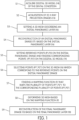
- the method comprises the following steps (S1-S9) as shown in Fig. 1 .
- step (S1) as shown in Fig. 2 , a digital 3D model (14) of a dental condition of the patient which describes the 3D surface of the teeth, and the gingiva is acquired.
- the digital 3D model (14) can be obtained through one or more of the following methods, e.g, through (i) optically scanning of the dental condition by means of an intraoral scanner (12) as shown in Fig. 12 and Fig.
- the digital 3D model (14) of the dental condition of the patient can already exist on the computing unit (8) of the dentist.
- a new digital 3D model (14) of the dental condition of the patient can be directly acquired before the x-ray panoramic imaging.
- a digital 3D model (14) of the patient can be obtained from another dentist via cloud data exchange.
- step (S2) two-dimensional x-ray projection images (15) as shown in Fig. 4 , are acquired by rotating the x-ray detector (4) and the x-ray source (3) along a trajectory around the patient's head.
- the system (1) has several x-ray panoramic acquisition modes for different patient anatomies. Each acquisition mode defines a specific trajectory of the x-ray detector (4) and the x-ray source (3) around the patient's head.
- step (S3) an initial panoramic layer (16) as shown in Fig. 5 , of the patient to be imaged relative to the trajectory is set.
- the initial panoramic layer (16) describes the area to be reconstructed in the 3D space and defines the dimensions (width, height, pixel size) of initial panoramic image (17) and the anatomical structures to be mapped within the patient's jaw.
- step (S4) an initial panoramic image (17) as shown in Fig. 6 , is reconstructed based on the initial panoramic layer (16) and the x-ray projection images (15).
- a conventional Shift&Add approach may be used for the reconstruction of the initial panoramic image (17).
- All exposed x-ray projection images (15) contribute to the initial panoramic image (17).
- the x-ray projection images may be postprocessed, e.g., offset (dark current) and gain (beam shape, pixel based signal deviation) corrected, before reconstructing the initial panoramic image (17).
- step (S5) a plurality of reference points (P1, P2) as shown in Fig. 7 , are set on the initial panoramic image (17).
- the number of reference points (P1, P2) may be also increased with the number of anatomical structures (A) to be used.
- the corresponding plurality of points (P1', P2') as shown in Fig. 8 are found on the digital 3D model (14). Additional image processing techniques such as pattern recognition or AI can be used to find the corresponding plurality of points (P1', P2') on the digital 3D model (14).
- step (S6) a plurality of points (P1", P2") as shown in Fig. 9 , are selected on the initial panoramic layer (16) which correspond to the plurality of reference points (P1, P2) set on the initial panoramic image (17).
- the initial panoramic layer (16) may have the same resolution as the initial panoramic image (17).
- the plurality of reference (P1, P2) points define x-y positions on the initial panoramic image (17) whereas the plurality of points (P1", P2”) define x-y-z coordinates on the initial panoramic layer (16) in 3D.
- For each reference point on the initial panoramic image (17) a corresponding point on the initial panoramic layer (16) exist.
- a mapping function (F) as shown inf Fig. 14 , is found that maps the plurality of points (P 1 ", P2") selected on the initial panoramic layer (16) to the corresponding plurality of points (P1', P2') found on the digital 3D model (14).
- the mapping function (F) can be defined per pixel (point), or group of pixels (group of points). The group of pixels may each define a dental region such as separate anatomical structure.
- the mapping function (F) may be represented trough a transformation matrix, including rotation, translation, scaling, and/or warping.
- step (S8) the initial panoramic layer (16) is deformed in accordance with the mapping function (F) to obtain a final panoramic layer (18). Additionally, a 3D blurring filter can be applied on the final panoramic layer (18) to remove any kind of outliers before reconstruction the final panoramic image (13).
- step (S9) the final panoramic image (13) as shown in Fig. 11 , is reconstructed based on the x-ray projection images (15) and the final panoramic layer (18).
- a conventional Shift&Add approach may be used for the reconstruction of the final panoramic image (13) .
- All exposed x-ray projection images (15) contribute to the initial panoramic image (17).
- the final panoramic image (13) can be displayed on the display device (9).
- the final panoramic image (13) can be displayed on the display device (9) as a planar 2D image or as a 3D image superposed on the final panoramic layer (18).
- the setting step (S5) comprises the following sub steps: In a first sub step, one or more anatomical structures (A) in the initial panoramic image (17) and the same anatomical structures (A) in the digital 3D model (14) as shown in Fig.8 , are determined.
- the plurality of reference points are set on the anatomical structures (A) in the initial panoramic image (17), and then the corresponding plurality of points on the corresponding anatomical structures are found in the digital 3D model (14).
- the anatomical structures (A) may include one or more of the following: tooth contour; tooth tips; tooth necks; tooth crowns; approximal teeth contacts; tooth roots; tooth root tips; tooth nerve canals; tooth pulp; periodontal gap.
- the selection of anatomical structures (A) to be used depends on the type of the digital 3D model (14) of the dental condition of the patient.
Landscapes
- Health & Medical Sciences (AREA)
- Life Sciences & Earth Sciences (AREA)
- Engineering & Computer Science (AREA)
- Medical Informatics (AREA)
- Physics & Mathematics (AREA)
- Heart & Thoracic Surgery (AREA)
- Surgery (AREA)
- Nuclear Medicine, Radiotherapy & Molecular Imaging (AREA)
- Optics & Photonics (AREA)
- Pathology (AREA)
- Radiology & Medical Imaging (AREA)
- Biomedical Technology (AREA)
- Biophysics (AREA)
- Molecular Biology (AREA)
- High Energy & Nuclear Physics (AREA)
- Animal Behavior & Ethology (AREA)
- General Health & Medical Sciences (AREA)
- Public Health (AREA)
- Veterinary Medicine (AREA)
- Dentistry (AREA)
- Oral & Maxillofacial Surgery (AREA)
- General Physics & Mathematics (AREA)
- Theoretical Computer Science (AREA)
- Apparatus For Radiation Diagnosis (AREA)
Abstract
Description
- The present invention relates to a computer-assisted x-ray system and a method of generating a final panoramic image of the dental condition of a patient.
- Panoramic images give dentists a quick overview of a patient's dental condition. Panoramic images are used by dentists to prepare for treatment and allow a quick initial diagnosis in problem cases. A panoramic image is a standard procedure of all extraoral dental radiographic procedures. A classic planar 2D representation of the panoramic image is commonly used by dentists. The panoramic image is generally reconstructed using a shift- and-add procedure or more complex procedures. A panoramic image depicts the anatomical structures located in a panoramic layer (a 3D mesh) to be mapped within the patient's jaw.
- Generally, in x-ray panoramic imaging, two-dimensional x-ray projection images are acquired by rotating an x-ray detector and an x-ray source along a trajectory around the patient's head. Usually, the panoramic layer is pre-set for the patients to be imaged relative to the trajectory. Finally, a panoramic image is reconstructed based on the panoramic layer and the x-ray projection images.
- The sharpness of the panoramic image is important for a correct diagnosis and the treatment. However, the sharpness depends significantly on the position of the panoramic layer relative to the patient's position and the patient specific dental condition.
- In the prior art, the positioning of the patient is usually achieved by using a bite block and /or a head fixture. Alternatively, the position of the patient can be determined by imaging techniques using scout shots. In the prior art, the sharpness of the panoramic image can be improved by commonly known autofocus techniques in which the panoramic layer is optimized through applying local sharpness measures to obtain a sharply reconstructed panoramic image.
- The above prior art techniques have the disadvantage that the patient is unnecessarily exposed with additional x-ray radiation for acquiring the scout shot information.
- Furthermore, the commonly used autofocus techniques require additional computational effort for the calculation of the optimal panoramic layer.
- An objective of the present invention is to provide a system and method for generating a panoramic image in which dental condition of the patient can be mapped with improved sharpness.
- This objectives is achieved by the method as defined in
claim 1, and the x-ray system as defined in claim 6. The subject-matters of the dependent claims define further developments and preferred embodiments. - The method according to the invention is a computer-implemented method and is used to generate a final panoramic image of the dental condition of a patient. The method comprises the following steps: acquiring a digital 3D model of a dental condition of the patient which describes the 3D surface of the teeth and the gingiva; acquiring two-dimensional x-ray projection images by rotating an x-ray detector and an x-ray source along a trajectory around the patient's head; setting an initial panoramic layer of the patient to be imaged relative to the trajectory; reconstructing an initial panoramic image based on the initial panoramic layer and the x-ray projection images; setting a plurality of reference points on the initial panoramic image, and finding the corresponding plurality of points on the digital 3D model; selecting a plurality of points on the initial panoramic layer which correspond to the plurality of reference points set on the initial panoramic image; finding a mapping function that maps the plurality of points selected on the initial panoramic layer to the corresponding plurality of points found on the digital 3D model; deforming the initial panoramic layer in accordance with the mapping function to obtain a final panoramic layer; reconstructing the final panoramic image based on the x-ray projection images and the final panoramic layer; displaying the final panoramic image.
- An advantageous effect of the invention is that the sharpness of the final panoramic layer can be improved by virtue of the digital 3D model of the dental condition of the patient, especially through deforming the initial panoramic layer to conform with the 3D surface of the teeth and the gingiva. The digital 3D model is used thereby as a pre-knowledge about the dental condition of the patient.
- In sum, the method according to the present invention creates diagnostic and therapeutic added value for the dentist through more reliable diagnosis due to the improved sharpness of the final panoramic layer. Thus, no additional sharpness measures, e.g., autofocus, or positioning means, e.g., scout shots are necessary because by virtue of the digital 3D model, a patient-specific deformed initial panoramic layer is used for the sharpness optimization.
- According to the present invention, the digital 3D model can be obtained through various methods. For example, the digital 3D model can be obtained through optically scanning of the dental condition by means of an intraoral scanner. For example, the digital 3D model can be obtained through optically scanning of an impression material by means of an intraoral scanner. For example, the digital 3D model can be obtained through using a 3D volume image which has been reconstructed from a set x-ray projection images of the patient's head. For example, the digital 3D model can be obtained through using a 3D volume image which has been reconstructed from a set of x-ray projections of an impression material of the patient's dental condition.
- According to the present invention, it is also optionally considered to additionally use anatomical structures of the dental condition when finding the mapping function. In this way, impairment of the mapping function by noise can be avoided or reduced as far as possible. These anatomical structures may include one or more of the following: tooth contour; tooth tips; tooth necks; tooth crowns; approximal teeth contacts; tooth roots; tooth root tips, tooth nerve canals, tooth pulp; periodontal gap.
- In the following description, the present invention will be explained in more detail with reference to the exemplary embodiments and with reference to the drawings, wherein.
- Fig. 1 -
- shows a flow chart of a method of generating a final panoramic image of a patient according to an embodiment of the invention;
- Fig. 2 -
- shows a digital 3D model of a dental condition of the patient according to an embodiment of the invention;
- Fig. 3 -
- shows a schematic drawing of an x-ray system according to an embodiment of the invention;
- Fig. 4 -
- shows at least some of the two-dimensional x-ray projection images acquired by rotating an x-ray detector and an x-ray source along a trajectory around the patient's head according to an embodiment of the invention;
- Fig. 5 -
- shows an initial panoramic layer (3D Mesh) of the patient to be imaged relative to the trajectory according to an embodiment of the invention;
- Fig. 6 -
- shows an initial panoramic image reconstructed based on the initial panoramic layer and the x-ray projection images according to an embodiment of the invention;
- Fig. 7 -
- shows a plurality of reference points set on the initial panoramic image, and an anatomical structure (A) according to an embodiment of the invention;
- Fig. 8 -
- shows corresponding plurality of points found on the digital 3D model and an anatomical structure (A) according to an embodiment of the invention;
- Fig. 9 -
- shows a plurality of points selected on the initial panoramic layer which correspond to the plurality of reference points set on the initial panoramic image according to an embodiment of the invention;
- Fig. 10 -
- shows a final panoramic layer obtained by deforming the initial panoramic layer in accordance with a mapping function as shown in
Fig. 14 according to an embodiment of the invention; - Fig. 11 -
- shows a final panoramic image reconstructed based on the x-ray projection images and the final panoramic layer according to an embodiment of the invention;
- Fig. 12 -
- shows a dentist acquiring a digital 3D model of a dental condition of the patient according to an embodiment of the invention;
- Fig. 13 -
- shows an x-ray system having an intraoral scanner according to an embodiment of the invention;
- Fig. 14 -
- shows a mapping function (F) that maps the plurality of points selected on the initial panoramic layer to the corresponding plurality of points found on the digital 3D model according to an embodiment of the invention.
- The reference numbers shown in the drawings designate the elements listed below, which are referred to in the following description of the exemplary embodiments.
- 1.
- X-ray system
- 2.
- X-ray device
- 3.
- X-ray source
- 4.
- X-ray detector
- 5.
- Operating unit (user interface)
- 6.
- Head fixation
- 7.
- Bite block
- 8.
- Computing unit (Computer)
- 9.
- Display device (Screen)
- 10.
- Input device (Keyboard)
- 11.
- Input device (Mouse)
- 12.
- Intraoral Scanner
- 13.
- Final panoramic image
- 14
- Digital 3D model (IO Scan)
- 15.
- X-ray projection images
- 16.
- Initial panoramic layer (or 3D Mesh)
- 17.
- Initial panoramic image
- 18.
- Final panoramic layer (or deformed 3D Mesh)
- The method according to the invention, which is explained in detail below, is a computer-implemented method and can be carried out on a computer-implemented x-ray system (1) as shown in an embodiment in
Fig. 3 . - The present invention also includes a corresponding computer program having computer-readable code for implementing the method. The computer program is provided on a computer readable storage medium accessible to the x-ray system (1). The computerized x-ray system (1) comprises an x-ray device (2) for performing patient imaging, which generates x-ray projection images (15) or a sinogram. The x-ray device (2) has an x-ray source (3) and an x-ray detector (4) that are rotated around the patient's head during the imaging. The trajectory of the x-ray source (3) and the x-ray detector (4) during the imaging can describe a circular path. However, it can also assume a form deviating from this. If several actuators (not shown) are controlled simultaneously, a trajectory deviating from a pure circular path around the patient's head can be achieved. The patient's head can be positioned in the x-ray device (2) with a bite block (7) and optionally with a head fixation (6). The trajectory (course) of the x-ray source (3) and the x-ray detector (4) with respect to the bite block (7) and the head fixation (6) are known by the system (1). The x-ray detector (4) detects the x-rays emitted by the x-ray source (3) during the rotation. The x-ray projection images (15) are acquired, namely read out from the x-ray detector (4). The computerized x-ray system (1) also comprises an operating unit (5) such as a user interface, a computing unit (8) e.g., a computer which can be connected to the x-ray device (2), and a display device (9) such as a screen for visualizing any data sets resulting from the method. The computer may be connected to the x-ray device (2) via a local area network (not shown) or, alternatively, via the Internet. The computer is connected to input devices such as a keyboard (10), mouse (11), and the like. The computer may be also part of a cloud. Alternatively, the computer may be integrated into the x-ray device (2). Alternatively, all or some of the computations may take place in the cloud as cloud computing. The computer executes the computer program and provides the data sets, e.g., the panoramic images for visualization on the screen. The screen may be provided spatially separate from or integrated with the x-ray device. Preferably, the computer may also control all functions of the x-ray device (2). Alternatively, separate computers may be used for the control, operation, and panoramic image reconstruction.
- The x-ray system (1) is preferably configurable as an IoT system and can be bidirectionally connected via a local area network and/or the internet (not shown) to other dental devices such as optical intraoral scanners (12), dental milling machines, additive manufacturing machines, and the like for cloud computing, data exchange, remote control, and the like.
- The computer implemented method is for generating a final panoramic image (13) of a patient. The method comprises the following steps (S1-S9) as shown in
Fig. 1 . - In step (S1), as shown in
Fig. 2 , a digital 3D model (14) of a dental condition of the patient which describes the 3D surface of the teeth, and the gingiva is acquired. The digital 3D model (14) can be obtained through one or more of the following methods, e.g, through (i) optically scanning of the dental condition by means of an intraoral scanner (12) as shown inFig. 12 and Fig. 13 , (ii) optically scanning of an impression material (not shown) by means of an intraoral scanner (12); (iii) using a 3D volume image which has been reconstructed from a set x-ray projection images of the patient's head, (iv) using a 3D volume image which has been reconstructed from a set of x-ray projections of an impression material of the patient's dental condition. - The digital 3D model (14) of the dental condition of the patient can already exist on the computing unit (8) of the dentist. Alternatively, a new digital 3D model (14) of the dental condition of the patient can be directly acquired before the x-ray panoramic imaging. Alternatively, a digital 3D model (14) of the patient can be obtained from another dentist via cloud data exchange.
- In step (S2), two-dimensional x-ray projection images (15) as shown in
Fig. 4 , are acquired by rotating the x-ray detector (4) and the x-ray source (3) along a trajectory around the patient's head. The system (1) has several x-ray panoramic acquisition modes for different patient anatomies. Each acquisition mode defines a specific trajectory of the x-ray detector (4) and the x-ray source (3) around the patient's head. - In step (S3), an initial panoramic layer (16) as shown in
Fig. 5 , of the patient to be imaged relative to the trajectory is set. The initial panoramic layer (16) describes the area to be reconstructed in the 3D space and defines the dimensions (width, height, pixel size) of initial panoramic image (17) and the anatomical structures to be mapped within the patient's jaw. - In step (S4), an initial panoramic image (17) as shown in
Fig. 6 , is reconstructed based on the initial panoramic layer (16) and the x-ray projection images (15). For the reconstruction of the initial panoramic image (17) a conventional Shift&Add approach may be used. All exposed x-ray projection images (15) contribute to the initial panoramic image (17). The x-ray projection images may be postprocessed, e.g., offset (dark current) and gain (beam shape, pixel based signal deviation) corrected, before reconstructing the initial panoramic image (17). - In step (S5), a plurality of reference points (P1, P2) as shown in
Fig. 7 , are set on the initial panoramic image (17). The number of reference points (P1, P2) may be also increased with the number of anatomical structures (A) to be used. Subsequently, the corresponding plurality of points (P1', P2') as shown inFig. 8 , are found on the digital 3D model (14). Additional image processing techniques such as pattern recognition or AI can be used to find the corresponding plurality of points (P1', P2') on the digital 3D model (14). - In step (S6), a plurality of points (P1", P2") as shown in
Fig. 9 , are selected on the initial panoramic layer (16) which correspond to the plurality of reference points (P1, P2) set on the initial panoramic image (17). The initial panoramic layer (16) may have the same resolution as the initial panoramic image (17). The plurality of reference (P1, P2) points define x-y positions on the initial panoramic image (17) whereas the plurality of points (P1", P2") define x-y-z coordinates on the initial panoramic layer (16) in 3D. For each reference point on the initial panoramic image (17) a corresponding point on the initial panoramic layer (16) exist. - In step (S7), a mapping function (F) as shown inf
Fig. 14 , is found that maps the plurality of points (P 1 ", P2") selected on the initial panoramic layer (16) to the corresponding plurality of points (P1', P2') found on the digital 3D model (14). The mapping function (F) can be defined per pixel (point), or group of pixels (group of points). The group of pixels may each define a dental region such as separate anatomical structure. The mapping function (F) may be represented trough a transformation matrix, including rotation, translation, scaling, and/or warping. - In step (S8), the initial panoramic layer (16) is deformed in accordance with the mapping function (F) to obtain a final panoramic layer (18). Additionally, a 3D blurring filter can be applied on the final panoramic layer (18) to remove any kind of outliers before reconstruction the final panoramic image (13).
- In step (S9), the final panoramic image (13) as shown in
Fig. 11 , is reconstructed based on the x-ray projection images (15) and the final panoramic layer (18). For the reconstruction of the final panoramic image (13) a conventional Shift&Add approach may be used. All exposed x-ray projection images (15) contribute to the initial panoramic image (17). Finally, the final panoramic image (13) can be displayed on the display device (9). The final panoramic image (13) can be displayed on the display device (9) as a planar 2D image or as a 3D image superposed on the final panoramic layer (18). - According to a variation of the above described embodiment, it is also optionally considered to additionally use anatomical structures (A) as shown in
Fig. 7 , of the dental condition when finding the mapping function (F). Additional image processing techniques such as pattern recognition or AI can be used. In this embodiment, the setting step (S5) comprises the following sub steps: In a first sub step, one or more anatomical structures (A) in the initial panoramic image (17) and the same anatomical structures (A) in the digital 3D model (14) as shown inFig.8 , are determined. Subsequently, in a second sub step, the plurality of reference points are set on the anatomical structures (A) in the initial panoramic image (17), and then the corresponding plurality of points on the corresponding anatomical structures are found in the digital 3D model (14). - In this embodiment, the anatomical structures (A) may include one or more of the following: tooth contour; tooth tips; tooth necks; tooth crowns; approximal teeth contacts; tooth roots; tooth root tips; tooth nerve canals; tooth pulp; periodontal gap.
- The selection of anatomical structures (A) to be used depends on the type of the digital 3D model (14) of the dental condition of the patient.
Claims (6)
- A computer implemented method of generating a final panoramic image (13) of a patient, comprising the steps of:acquiring (S1) a digital 3D model (14) of a dental condition of the patient which describes the 3D surface of the teeth and the gingiva;acquiring (S2) two-dimensional x-ray projection images (15) by rotating an x-ray detector (4) and an x-ray source (3) along a trajectory around the patient's head;setting (S3) an initial panoramic layer (16) of the patient to be imaged relative to the trajectory;reconstructing (S4) an initial panoramic image (17) based on the initial panoramic layer (16) and the x-ray projection images (15);setting (S5) a plurality of reference points (P1, P2) on the initial panoramic image (17), and finding the corresponding plurality of points (P1', P2') on the digital 3D model (14);selecting (S6) a plurality of points (P1", P2") on the initial panoramic layer (16) which correspond to the plurality of reference points (P 1, P2) set on the initial panoramic image (17);finding (S7) a mapping function (F) that maps the plurality of points (P1", P2") selected on the initial panoramic layer (16) to the corresponding plurality of points (PI , P2') found on the digital 3D model (14);deforming (S8) the initial panoramic layer (16) in accordance with the mapping function (F) to obtain a final panoramic layer (18);reconstructing (S9) the final panoramic image (13) based on the x-ray projection images (15) and the final panoramic layer (18);displaying the final panoramic image (13).
- The method according to claim 1, characterized in that
in the acquiring step (S1) the digital 3D model (14) can be obtained through one or more of the following methods:- optically scanning of the dental condition by means of an intraoral scanner (12);- optically scanning of an impression material by means of an intraoral scanner (12); or- using a 3D volume image which has been reconstructed from a set x-ray projection images of the patient's head;- using a 3D volume image which has been reconstructed from a set of x-ray projection images of an impression material of the patient's dental condition. - The method according to claim 1 or 2, characterized in that in the setting step (S5) comprises the subs steps of:determining one or more anatomical structures (A) in the initial panoramic image (17) and the same anatomical structures (A) in the digital 3D model (14);setting the plurality of reference points on the anatomical structures in the initial panoramic image (17), and finding the corresponding plurality of points on the corresponding anatomical structures in the digital 3D model (14).
- The method according to claim 3, characterized in that anatomical structures (A) include one or more of the following:tooth contour;tooth tips;tooth necks;tooth crowns;approximal teeth contacts;tooth roots;tooth root tipstooth nerve canalstooth pulp;periodontal gap.
- A computer program comprising computer-readable code which, when executed by a computer-assisted x-ray system (1), causes the system (1) to perform the method of any one of the preceding claims.
- A computer-assisted x-ray system (1) comprising a computing unit (8) configured to execute the computer program according to claim 5.
Priority Applications (2)
| Application Number | Priority Date | Filing Date | Title |
|---|---|---|---|
| EP23198691.0A EP4528630B1 (en) | 2023-09-21 | 2023-09-21 | Method of generating a final panoramic image using a digital 3d model of the dental condition of a patient |
| PCT/EP2024/073786 WO2025061416A1 (en) | 2023-09-21 | 2024-08-26 | Method of generating a final panoramic image using a digital 3d model of the dental condition of a patient |
Applications Claiming Priority (1)
| Application Number | Priority Date | Filing Date | Title |
|---|---|---|---|
| EP23198691.0A EP4528630B1 (en) | 2023-09-21 | 2023-09-21 | Method of generating a final panoramic image using a digital 3d model of the dental condition of a patient |
Publications (2)
| Publication Number | Publication Date |
|---|---|
| EP4528630A1 true EP4528630A1 (en) | 2025-03-26 |
| EP4528630B1 EP4528630B1 (en) | 2026-04-22 |
Family
ID=88146587
Family Applications (1)
| Application Number | Title | Priority Date | Filing Date |
|---|---|---|---|
| EP23198691.0A Active EP4528630B1 (en) | 2023-09-21 | 2023-09-21 | Method of generating a final panoramic image using a digital 3d model of the dental condition of a patient |
Country Status (2)
| Country | Link |
|---|---|
| EP (1) | EP4528630B1 (en) |
| WO (1) | WO2025061416A1 (en) |
Citations (2)
| Publication number | Priority date | Publication date | Assignee | Title |
|---|---|---|---|---|
| KR101146862B1 (en) * | 2010-12-02 | 2012-05-16 | 이준호 | Method to change from two-dimensional panorama picture to three-dimensional picture and the recorded media thereof |
| US20200234404A1 (en) * | 2017-09-28 | 2020-07-23 | 3Shape A/S | Method and system for generating a panoramic image |
-
2023
- 2023-09-21 EP EP23198691.0A patent/EP4528630B1/en active Active
-
2024
- 2024-08-26 WO PCT/EP2024/073786 patent/WO2025061416A1/en not_active Ceased
Patent Citations (2)
| Publication number | Priority date | Publication date | Assignee | Title |
|---|---|---|---|---|
| KR101146862B1 (en) * | 2010-12-02 | 2012-05-16 | 이준호 | Method to change from two-dimensional panorama picture to three-dimensional picture and the recorded media thereof |
| US20200234404A1 (en) * | 2017-09-28 | 2020-07-23 | 3Shape A/S | Method and system for generating a panoramic image |
Non-Patent Citations (1)
| Title |
|---|
| BARONE SANDRO ET AL: "Geometrical modeling of complete dental shapes by using panoramic X-ray, digital mouth data and anatomical templates", COMPUTERIZED MEDICAL IMAGING AND GRAPHICS, PERGAMON PRESS, NEW YORK, NY, US, vol. 43, 20 January 2015 (2015-01-20), pages 112 - 121, XP029244417, ISSN: 0895-6111, DOI: 10.1016/J.COMPMEDIMAG.2015.01.005 * |
Also Published As
| Publication number | Publication date |
|---|---|
| WO2025061416A1 (en) | 2025-03-27 |
| EP4528630B1 (en) | 2026-04-22 |
Similar Documents
| Publication | Publication Date | Title |
|---|---|---|
| EP3595574B1 (en) | Automatic dental arch mapping system and method | |
| CN110313037B (en) | Longitudinal analysis and visualization under limited precision system | |
| JP6483273B2 (en) | Automatic selection and locking of intraoral images | |
| CN108463170B (en) | X-ray image display apparatus and X-ray image display method | |
| US11045290B2 (en) | Dynamic dental arch map | |
| Scarfe et al. | Cone beam computed tomography: volume acquisition | |
| EP2973401B1 (en) | Method for producing teeth surface from x-ray scan of a negative impression | |
| EP2564375A1 (en) | Virtual cephalometric imaging | |
| Yoon et al. | Digital radiographic image processing and analysis | |
| US20240338865A1 (en) | Optimization of extraoral panoramic images through model-based prior knowledge of the patient's jaw arch form | |
| US20250209644A1 (en) | Method of automatically matching of a ct dental volume and a digital dental impression of a patient using neural networks | |
| JP7152738B2 (en) | Image processing device and image processing program | |
| EP4528630B1 (en) | Method of generating a final panoramic image using a digital 3d model of the dental condition of a patient | |
| EP4375928A1 (en) | Method for length measurement within dental panoramic images | |
| Barone et al. | Geometrical modeling of complete dental shapes by using panoramic X-ray, digital mouth data and anatomical templates | |
| US12544018B2 (en) | Method for digital volume tomography imaging of a small volume | |
| EP4331497A1 (en) | X-ray system for the production of dental panoramic images with several offset individual x-ray emitters | |
| EP4606313A1 (en) | Method of generating a cephalometric image of a patient's head with reduced chatter marks | |
| Prativi et al. | Development of cephalometric radiography in orthodontic imaging: a literature review | |
| US20250380923A1 (en) | Method for artifact reduction in cone beam computed tomography images | |
| US20250029292A1 (en) | Method and system for generating dental panoramic images with sharpened depiction of clinically relevant, patient-specific pre-selected anatomical structures |
Legal Events
| Date | Code | Title | Description |
|---|---|---|---|
| PUAI | Public reference made under article 153(3) epc to a published international application that has entered the european phase |
Free format text: ORIGINAL CODE: 0009012 |
|
| STAA | Information on the status of an ep patent application or granted ep patent |
Free format text: STATUS: THE APPLICATION HAS BEEN PUBLISHED |
|
| AK | Designated contracting states |
Kind code of ref document: A1 Designated state(s): AL AT BE BG CH CY CZ DE DK EE ES FI FR GB GR HR HU IE IS IT LI LT LU LV MC ME MK MT NL NO PL PT RO RS SE SI SK SM TR |
|
| STAA | Information on the status of an ep patent application or granted ep patent |
Free format text: STATUS: REQUEST FOR EXAMINATION WAS MADE |
|
| 17P | Request for examination filed |
Effective date: 20250918 |
|
| GRAP | Despatch of communication of intention to grant a patent |
Free format text: ORIGINAL CODE: EPIDOSNIGR1 |
|
| STAA | Information on the status of an ep patent application or granted ep patent |
Free format text: STATUS: GRANT OF PATENT IS INTENDED |
|
| RIC1 | Information provided on ipc code assigned before grant |
Ipc: G06T 3/4038 20240101AFI20251123BHEP Ipc: A61B 6/46 20240101ALI20251123BHEP Ipc: A61B 6/02 20060101ALI20251123BHEP Ipc: A61B 6/51 20240101ALI20251123BHEP |
|
| INTG | Intention to grant announced |
Effective date: 20251204 |
|
| GRAS | Grant fee paid |
Free format text: ORIGINAL CODE: EPIDOSNIGR3 |
|
| GRAA | (expected) grant |
Free format text: ORIGINAL CODE: 0009210 |
|
| STAA | Information on the status of an ep patent application or granted ep patent |
Free format text: STATUS: THE PATENT HAS BEEN GRANTED |
|
| AK | Designated contracting states |
Kind code of ref document: B1 Designated state(s): AL AT BE BG CH CY CZ DE DK EE ES FI FR GB GR HR HU IE IS IT LI LT LU LV MC ME MK MT NL NO PL PT RO RS SE SI SK SM TR |
|
| P01 | Opt-out of the competence of the unified patent court (upc) registered |
Free format text: CASE NUMBER: UPC_APP_0009939_4528630/2026 Effective date: 20260313 |
|
| REG | Reference to a national code |
Ref country code: CH Ref legal event code: F10 Free format text: ST27 STATUS EVENT CODE: U-0-0-F10-F00 (AS PROVIDED BY THE NATIONAL OFFICE) Effective date: 20260422 Ref country code: GB Ref legal event code: FG4D |
|
| REG | Reference to a national code |
Ref country code: DE Ref legal event code: R096 Ref document number: 602023015626 Country of ref document: DE |
|
| REG | Reference to a national code |
Ref country code: IE Ref legal event code: FG4D |