EP4528562A1 - Attack source identification system, attack source identification device, attack source identification method, and program - Google Patents
Attack source identification system, attack source identification device, attack source identification method, and program Download PDFInfo
- Publication number
- EP4528562A1 EP4528562A1 EP22942685.3A EP22942685A EP4528562A1 EP 4528562 A1 EP4528562 A1 EP 4528562A1 EP 22942685 A EP22942685 A EP 22942685A EP 4528562 A1 EP4528562 A1 EP 4528562A1
- Authority
- EP
- European Patent Office
- Prior art keywords
- electronic control
- message
- attack
- control devices
- history information
- Prior art date
- Legal status (The legal status is an assumption and is not a legal conclusion. Google has not performed a legal analysis and makes no representation as to the accuracy of the status listed.)
- Pending
Links
Images




Classifications
-
- G—PHYSICS
- G06—COMPUTING OR CALCULATING; COUNTING
- G06F—ELECTRIC DIGITAL DATA PROCESSING
- G06F21/00—Security arrangements for protecting computers, components thereof, programs or data against unauthorised activity
- G06F21/50—Monitoring users, programs or devices to maintain the integrity of platforms, e.g. of processors, firmware or operating systems
- G06F21/55—Detecting local intrusion or implementing counter-measures
- G06F21/552—Detecting local intrusion or implementing counter-measures involving long-term monitoring or reporting
-
- H—ELECTRICITY
- H04—ELECTRIC COMMUNICATION TECHNIQUE
- H04L—TRANSMISSION OF DIGITAL INFORMATION, e.g. TELEGRAPHIC COMMUNICATION
- H04L12/00—Data switching networks
- H04L12/28—Data switching networks characterised by path configuration, e.g. LAN [Local Area Networks] or WAN [Wide Area Networks]
-
- H—ELECTRICITY
- H04—ELECTRIC COMMUNICATION TECHNIQUE
- H04L—TRANSMISSION OF DIGITAL INFORMATION, e.g. TELEGRAPHIC COMMUNICATION
- H04L63/00—Network architectures or network communication protocols for network security
- H04L63/14—Network architectures or network communication protocols for network security for detecting or protecting against malicious traffic
- H04L63/1408—Network architectures or network communication protocols for network security for detecting or protecting against malicious traffic by monitoring network traffic
- H04L63/1416—Event detection, e.g. attack signature detection
-
- H—ELECTRICITY
- H04—ELECTRIC COMMUNICATION TECHNIQUE
- H04L—TRANSMISSION OF DIGITAL INFORMATION, e.g. TELEGRAPHIC COMMUNICATION
- H04L63/00—Network architectures or network communication protocols for network security
- H04L63/14—Network architectures or network communication protocols for network security for detecting or protecting against malicious traffic
- H04L63/1408—Network architectures or network communication protocols for network security for detecting or protecting against malicious traffic by monitoring network traffic
- H04L63/1425—Traffic logging, e.g. anomaly detection
-
- H—ELECTRICITY
- H04—ELECTRIC COMMUNICATION TECHNIQUE
- H04W—WIRELESS COMMUNICATION NETWORKS
- H04W12/00—Security arrangements; Authentication; Protecting privacy or anonymity
- H04W12/009—Security arrangements; Authentication; Protecting privacy or anonymity specially adapted for networks, e.g. wireless sensor networks, ad-hoc networks, RFID networks or cloud networks
-
- H—ELECTRICITY
- H04—ELECTRIC COMMUNICATION TECHNIQUE
- H04L—TRANSMISSION OF DIGITAL INFORMATION, e.g. TELEGRAPHIC COMMUNICATION
- H04L12/00—Data switching networks
- H04L12/28—Data switching networks characterised by path configuration, e.g. LAN [Local Area Networks] or WAN [Wide Area Networks]
- H04L12/40—Bus networks
- H04L2012/40208—Bus networks characterized by the use of a particular bus standard
- H04L2012/40215—Controller Area Network CAN
-
- H—ELECTRICITY
- H04—ELECTRIC COMMUNICATION TECHNIQUE
- H04L—TRANSMISSION OF DIGITAL INFORMATION, e.g. TELEGRAPHIC COMMUNICATION
- H04L12/00—Data switching networks
- H04L12/28—Data switching networks characterised by path configuration, e.g. LAN [Local Area Networks] or WAN [Wide Area Networks]
- H04L12/40—Bus networks
- H04L2012/40267—Bus for use in transportation systems
- H04L2012/40273—Bus for use in transportation systems the transportation system being a vehicle
-
- H—ELECTRICITY
- H04—ELECTRIC COMMUNICATION TECHNIQUE
- H04L—TRANSMISSION OF DIGITAL INFORMATION, e.g. TELEGRAPHIC COMMUNICATION
- H04L2463/00—Additional details relating to network architectures or network communication protocols for network security covered by H04L63/00
- H04L2463/121—Timestamp
-
- H—ELECTRICITY
- H04—ELECTRIC COMMUNICATION TECHNIQUE
- H04L—TRANSMISSION OF DIGITAL INFORMATION, e.g. TELEGRAPHIC COMMUNICATION
- H04L2463/00—Additional details relating to network architectures or network communication protocols for network security covered by H04L63/00
- H04L2463/146—Tracing the source of attacks
Definitions
- the present disclosure relates to an attack source identifying system, an attack source identifying apparatus, an attack source identifying method, and a program.
- Some machines such as a vehicle (for example, an automobile, a special vehicle, a motorcycle, a bicycle, or the like), a machine tool, a construction machine, an agricultural machine, and an industrial machine are equipped with a plurality of electronic control units (ECUs).
- ECUs electronice control units
- a typical communication network between these ECUs is a controller area network (CAN).
- CAN controller area network
- Communication between the ECUs on the CAN (also referred to as CAN communication or a CAN message, or simply referred to as a message) includes an ID (also referred to as a CAN-ID) and a payload.
- the CAN-ID is used for identification of data contents, transmission nodes, and the like, determination of priority order of communication arbitration, and the like.
- data of up to 8 bytes is mounted, and the data includes values of one or more signals.
- signals related to states and control of speed, lateral speed, an accelerator, a brake, acceleration, a steering angle, and the like.
- Non Patent Literature 1 discloses a system of monitoring a CAN communication network and detecting insertion of an attack CAN message as an abnormality (network-type CAN-IDS).
- the network-type CAN-IDS is installed at a position where CAN communication can be overlooked.
- CGW central gateway
- Non Patent Literature 1 Satoshi Otsuka, Tasuku Ishigooka, "Intrusion Detection for In-vehicle Networks without Modifying Legacy ECUs", IPSJ SIG Technical Report, Vol.2013-EMB-28, No.6, pp.31-35, 2013 .
- CAN communication does not include transmission source and transmission destination addresses, and the network-type CAN-IDS cannot identify which device (and which process in the device) is the attack source.
- a hosted CAN-IDS installed in each ECU can identify a transmission source of an attack at the same time as detection of the attack in a case where the ECU is the attack source.
- the hosted CAN-IDS may not be able to detect an attack that inserts an attack CAN message. For example, consider a case where an attack CAN message is transmitted at a predetermined cycle from an ECU connected to a CAN bus different from that of an ECU that transmits a normal CAN message.
- the hosted CAN-IDS of the ECU that transmits the attack CAN message cannot observe the normal CAN message because its CAN bus is different from that of the ECU that transmits the normal CAN message. Therefore, the hosted CAN-IDS of the ECU that transmits the attack CAN message may recognize an observation cycle of the attack CAN message as a predetermined cycle, and the attack may not be detected.
- the present disclosure has been made in view of the above points, and provides a technique for identifying a transmission source of attack communication.
- An attack source identifying system is an attack source identifying system including: a plurality of electronic control devices; a gateway device communicably connected to the plurality of electronic control devices; and an analysis device communicably connected to the plurality of electronic control devices, wherein each of the electronic control devices includes: a creation unit configured to create history information of messages transmitted from a process executed by the electronic control device; and a transmission unit configured to transmit at least a part of the history information to the analysis device, the gateway device includes a detection unit configured to detect an attack message from messages transmitted and received by the plurality of electronic control devices, and the analysis device includes an identification unit configured to identify a transmission source of the attack message by using detection information related to the attack message and information received from the plurality of electronic control devices in a case where the attack message is detected.
- a CAN is assumed as a control network, and an attack source identifying system 1 capable of identifying an attack source of attack CAN communication (that is, an ECU that has transmitted the attack CAN communication, a process in the ECU, and the like) will be mainly described.
- the attack CAN communication refers to unauthorized CAN communication intended to make some kind of attack.
- CAN communication may be referred to as, for example, a CAN message, or simply referred to as a message.
- attack CAN communication is detected by a network-type CAN-IDS, and in a case where attack CAN communication is detected, a history of CAN communication transmitted (output) by each ECU and the detection result are compared, so that an attack source is identified.
- the attack source identifying system according to the present embodiment mainly includes the following three functional units.
- History collection unit 110 a functional unit that records, as a history, CAN communication transmitted by a process of a device such as an ECU and transmits the history to an analysis unit 310.
- Detection unit 210 a functional unit that detects attack CAN communication by the network-type CAN-IDS.
- Analysis unit 310 a functional unit that compares the detection result by the detection unit 210 with the history received from the history collection unit 110 to identify a transmission source of the attack CAN communication.
- CAN is assumed as a control network, but the control network is not limited to CAN.
- the present embodiment is similarly applicable to a case where network-type attack detection is performed on a communication protocol in which no source address is included in a communication message or a communication protocol in which, even if a source address is included, it is easy to falsify the source address.
- Example 1 is a case where the attack source identifying system 1 includes a monitoring network implemented by any communication system in addition to a control network implemented by CAN buses.
- Fig. 1 illustrates an overall configuration of the attack source identifying system 1 according to Example 1.
- the attack source identifying system 1 according to Example 1 includes a plurality of ECUs 10, a CGW 20, and an analysis device 30.
- the ECUs 10 and the CGW 20 are connected to CAN buses 40.
- each of the ECUs 10, the CGW 20, and the analysis device 30 are connected to a monitoring NW 50, which is a monitoring network.
- each of the plurality of ECUs 10 is denoted as “ECU 10-1", “ECU 10-2”, “ECU 10-11", “ECU 10-12”, or the like.
- the example illustrated in Fig. 1 includes the plurality of CAN buses 40, and each of the plurality of CAN buses 40 is denoted as “CAN bus 40-1", “CAN bus 40-2”, or the like.
- the attack source identifying system 1 has a central gateway type network configuration.
- the ECU 10-1, the ECU 10-2, and the like are connected to the CAN bus 40-1
- the ECU 10-11, the ECU 10-12, and the like are connected to the CAN bus 40-2.
- the CGW 20 exists as a central gateway, and is connected to both the CAN bus 40-1 and the CAN bus 40-2.
- the ECUs 10 are electronic control units. Each of the ECUs 10 includes a history collection unit 110.
- the history collection unit 110 is implemented, for example, by processing that one or more programs (including a module) held by the ECU 10 causes an arithmetic device such as a processor to execute.
- the history collection unit 110 of the ECU 10-1 is denoted as "history collection unit 110-1”
- the history collection unit 110 of the ECU 10-2 is denoted as “history collection unit 110-2”
- the history collection unit 110 of the ECU 10-11 is denoted as "history collection unit 110-11”
- the history collection unit 110 of the ECU 10-12 is denoted as "history collection unit 110-12”.
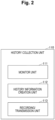
- Fig. 2 illustrates a detailed functional configuration of the history collection unit 110.
- the history collection unit 110 includes a monitor unit 111, a history information creation unit 112, and a recording/transmission unit 113.
- the monitor unit 111 monitors a process of the ECU 10 including the history collection unit 110, and in a case where the process transmits (outputs) CAN communication, the monitor unit 111 acquires, from the CAN communication, information such as a CAN-ID, a payload, and a process name of the process that has output the CAN communication. Note that the monitor unit 111 may acquire information such as a CAN-ID, a payload, and a process name not only from CAN communication transmitted by the process but also from CAN communication received by the process.
- the monitor unit 111 requires high speed, and thus is preferably implemented by a kernel module or a program operating in a kernel space.
- a kernel module for example, extended Berkeley Packet Filter (eBPF) can be used in Linux (registered trademark), and BPF, DTrace, or the like can be used in BSD and QNX.
- eBPF extended Berkeley Packet Filter
- Linux registered trademark
- BPF, DTrace, or the like can be used in BSD and QNX.
- the history information creation unit 112 creates history information from various types of information acquired by the monitor unit 111. At this time, the history information creation unit 112 creates the history information by performing predetermined statistical processing, necessary processing, and the like on the various types of information.
- the recording/transmission unit 113 records the history information created by the history information creation unit 112 in a memory included in the ECU 10, and transmits the history information to which its own ECU name is assigned to the analysis device 30 via the monitoring NW 50. Note that, when transmitting the history information to which its own ECU name is assigned to the analysis device 30, the recording/transmission unit 113 may transmit all the history information, or may select history information as necessary and transmit only a part of history information (for example, only history information that has not been transmitted yet).
- Fig. 3 illustrates an example of the history information.
- the history information includes a plurality of rows (records), and each row includes a time, an output CAN-ID, the number of outputs, entropy, and an output process name.
- Each of the rows constituting the history information is obtained by statistically processing various types of information acquired by the monitor unit 111 with the same CAN-ID every predetermined period (one minute in the example illustrated in Fig. 3 ).
- the number of outputs is the number of transmissions of CAN communication having the CAN-ID in the period.
- the entropy is the magnitude of the change amount of the payload of CAN communication having the CAN-ID in the period.
- the output process name is a process name that has output (transmitted) CAN communication having the CAN-ID.
- the example illustrated in Fig. 3 is history information created by the history collection unit 110 of a certain ECU 10 from which CAN communication having one of three CAN-IDs (32A, 32C, and 32E) is usually transmitted. As illustrated in Fig. 3 , in this history information, it is recorded that a malware process attack transmits many (the number of outputs "500") pieces of CAN communication of the same payload (that is, entropy "0") with the CAN-ID "0AA”.
- the analysis device 30 is a device that identifies a transmission source (attack source) of the attack CAN communication.
- the analysis device 30 includes the analysis unit 310.
- the analysis unit 310 is implemented, for example, by processing that one or more programs (including a module) held by the analysis device 30 causes an arithmetic device such as a processor to execute.
- the analysis unit 310 holds the history information (history information to which the ECU name is assigned) received from the history collection unit 110 in a memory of the analysis device 30. Note that the analysis unit 310 may delete (clear) the history information held in the memory, for example, in a case where a predetermined period has elapsed or in a case where history information with the same ECU name as the history information already held is received.
- the analysis unit 310 compares the detection information with the history information held in the memory, and identifies the transmission source of the attack CAN communication. That is, the analysis unit 310 compares the time (detection time) and the CAN-ID included in the detection information with times and CAN-IDs included in pieces of history information, and identifies the ECU 10 with the ECU name assigned to the history information including the matching time and CAN-ID and the process with the output process name corresponding to the time and CAN-ID as the transmission sources (attack sources) of the attack CAN communication.
- the times do not need to completely match, and may be determined to match as long as the difference therebetween falls within a predetermined range.
- only the CAN-IDs may be used for comparison without use of the times.
- the analysis device 30 may exist inside a machine (for example, a vehicle or the like) on which the ECU 10 and the CGW 20 are mounted, or may exist outside the machine and be capable of communicating with the devices in a wired or wireless manner.
- the monitor unit 111 of the history collection unit 110 acquires information such as a CAN-ID, a payload, and a process name from the CAN communication (step S101).
- the history information creation unit 112 of the history collection unit 110 creates history information from various types of information acquired by the monitor unit 111 every predetermined period (for example, one minute) (step S102). At this time, the history information creation unit 112 creates the history information by performing predetermined statistical processing (for example, calculation of the number of outputs, calculation of entropy, and the like), necessary processing (for example, data format conversion or the like as necessary), and the like on the various types of information.
- predetermined statistical processing for example, calculation of the number of outputs, calculation of entropy, and the like
- necessary processing for example, data format conversion or the like as necessary
- the recording/transmission unit 113 of the history collection unit 110 records the history information created by the history information creation unit 112 in a memory included in the ECU 10, and transmits the history information to which the ECU name of the ECU 10 is assigned to the analysis device 30 via the monitoring NW 50 (step S103). As a result, the history information to which the ECU name is assigned is held in the memory of the analysis device 30 by the analysis unit 310 of the analysis device 30.
- Example 1 attack detection and attack source identification processing in Example 1 will be described with reference to Fig. 5 .
- the detection unit 210 of the CGW 20 transmits detection information to the analysis device 30 (step S202).
- the analysis unit 310 of the analysis device 30 compares the time (detection time) and the CAN-ID included in the detection information received from the CGW 20 with the times and the CAN-IDs included in the pieces of history information held in the memory, and identifies the ECU name and the process name of the attack source (step S203).
- the analysis unit 310 may perform the above-described comparison after waiting until the latest history information is received from all the ECUs 10.
- the analysis unit 310 can compare the CAN-ID included in the detection information received from the CGW 20 with the CAN-IDs included in the pieces of history information held in the memory, and identify the ECU name and the process name corresponding to the matching CAN-ID as the attack sources.
- the analysis unit 310 identifies a plurality of transmission sources as attack source candidates by the above-described comparison, and then identifies the actual attack source from among the candidates.
- Examples of a method of identifying the actual attack source from among the plurality of attack source candidates include a method of using association information between each of an ECU name and a process name and a CAN-ID determined in advance by design or the like to identify an ECU name and a process name not included in the association information as the actual attack sources.
- an attack source candidate that has transmitted CAN communication of the CAN-ID at the time matching the time included in the detection information (detection time) may be identified as the actual attack source.
- Example 2 is a case where the attack source identifying system 1 does not include the monitoring NW 50, for example, due to cost constraints or the like. Note that, in Example 2, differences from Example 1 will be mainly described, and the description of components similar to those of Example 1 will be omitted.
- Fig. 6 illustrates an overall configuration of the attack source identifying system 1 according to Example 2.
- the attack source identifying system 1 according to Example 2 does not include the monitoring NW 50. Therefore, the history collection unit 110 of each of the ECUs 10 transmits history information to the analysis device 30 via one of the CAN buses 40 (and the CGW 20).
- the communication amount of the history information is preferably as small as possible. Therefore, in the present example, the recording/transmission unit 113 of the history collection unit 110 transmits an excerpt of history information to the analysis device 30.
- the CGW 20 and the analysis device 30 are communicably connected by any communication system.
- Example 2 recording and transmission processing of history information in Example 2 will be described with reference to Fig. 7 .
- recording and transmission processing of history information related to a certain ECU 10 will be described as an example.
- steps S301 to S302 in Fig. 7 are similar to steps S101 to S102 in Fig. 4 , the description thereof will be omitted.
- the recording/transmission unit 113 of the history collection unit 110 records history information created by the history information creation unit 112 in a memory included in the ECU 10, and transmits an excerpt of the history information (hereinafter, referred to as a history information excerpt) to the analysis device 30 via the CAN bus 40 to which the ECU 10 is connected (step S303).
- a history information excerpt is held in the memory of the analysis device 30 by the analysis unit 310 of the analysis device 30.
- the recording/transmission unit 113 can create the history information excerpt from a row in a predetermined period (for example, one minute) of the history information, and transmit the history information excerpt in one frame of CAN communication. Furthermore, the recording/transmission unit 113 transmits the CAN communication using a value unique to the ECU 10 as a CAN-ID. By setting the CAN-ID of the CAN communication representing the history information excerpt to the unique value for each of the ECUs 10, the analysis unit 310 of the analysis device 30 can identify which ECU 10 has transmitted the history information excerpt as the CAN communication.
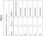
- Fig. 8 illustrates an example of bit assignment (bit assignment of a CAN frame) in a case where a history information excerpt is represented by one frame in a standard format of CAN communication.
- Fig. 8 illustrates an example of bit assignment in a case where CAN-IDs output during a predetermined period (for example, one minute) are extracted as a history information excerpt.
- the example illustrated in Fig. 8 indicates that the CAN-ID "700" is designated for CAN communication when the ECU 10-1 transmits a history information excerpt.
- Fig. 9 illustrates an example of bit assignment (bit assignment of a CAN frame) in a case where a history information excerpt is represented by one frame in an extended format of CAN communication.
- Fig. 9 illustrates an example of bit assignment in a case where the number of outputs of CAN-IDs output during a predetermined period (for example, one minute) is extracted as a history information excerpt.
- the example illustrated in Fig. 9 indicates that the CAN-ID "700" is designated for CAN communication when the ECU 10-1 transmits a history information excerpt.
- CAN-IDs are represented by a 29 bit length.
- the number of outputs of a CAN-ID can be designated every four bits.
- the number of outputs of the CAN-ID is collectively designated as the "number of outputs of other IDs".
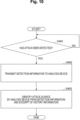
- steps S401 to S402 in Fig. 10 are similar to steps S201 to S202 in Fig. 5 , the description thereof will be omitted.
- the analysis unit 310 of the analysis device 30 identifies the attack source using the detection information received from the CGW 20 and the pieces of history information excerpt held in the memory (step S403). At this time, the analysis unit 310 may acquire history information that is not an excerpt from the corresponding ECU 10 as necessary, and then perform comparison similar to that in Example 1 to identify the attack source.
- the analysis unit 310 can identify the attack source (ECU 10) by comparing the CAN-ID included in the detection information with CAN-IDs included in history information excerpts. Therefore, the analysis unit 310 may further acquire history information from the ECU 10 and then identify the attack source process.
- the analysis unit 310 may acquire the history information corresponding to the history information excerpt from the corresponding ECU 10, and then perform comparison similar to that in Example 1 to identify the attack source.
- history information can be acquired via the CAN bus 40, for example, by the analysis unit 310 being mounted as an ECU diagnostic function.
- the attack source identifying system 1 in Example 3 may be a combination of Example 1 and Example 2. That is, in the attack source identifying system 1 according to Example 3, only some of the ECUs 10 (for example, the ECU 10-1, the ECU 10-2, and the like) may be connected to the monitoring NW 50, and the other ECUs 10 (for example, the ECU 10-11, the ECU 10-12, and the like) may not be connected to the monitoring NW 50. In this case, the ECUs 10 connected to the monitoring NW 50 can be similar to those in Example 1, and the ECUs 10 not connected to the monitoring NW 50 can be similar to those in Example 3.
- the ECUs 10 connected to the monitoring NW 50 can be similar to those in Example 1
- the ECUs 10 not connected to the monitoring NW 50 can be similar to those in Example 3.
- the attack source identifying system 1 can identify an attack source by comparison with history information such as a transmission history of messages. Therefore, for example, it is possible to efficiently perform cyberattack analysis.
Landscapes
- Engineering & Computer Science (AREA)
- Computer Security & Cryptography (AREA)
- Computer Networks & Wireless Communication (AREA)
- Signal Processing (AREA)
- Computer Hardware Design (AREA)
- General Engineering & Computer Science (AREA)
- Computing Systems (AREA)
- Software Systems (AREA)
- Theoretical Computer Science (AREA)
- Physics & Mathematics (AREA)
- General Physics & Mathematics (AREA)
- Small-Scale Networks (AREA)
Abstract
Description
- The present disclosure relates to an attack source identifying system, an attack source identifying apparatus, an attack source identifying method, and a program.
- Some machines such as a vehicle (for example, an automobile, a special vehicle, a motorcycle, a bicycle, or the like), a machine tool, a construction machine, an agricultural machine, and an industrial machine are equipped with a plurality of electronic control units (ECUs). In addition, a typical communication network between these ECUs is a controller area network (CAN). Communication between the ECUs on the CAN (also referred to as CAN communication or a CAN message, or simply referred to as a message) includes an ID (also referred to as a CAN-ID) and a payload. The CAN-ID is used for identification of data contents, transmission nodes, and the like, determination of priority order of communication arbitration, and the like. In the payload, data of up to 8 bytes is mounted, and the data includes values of one or more signals. Taking a vehicle as an example, there are signals related to states and control of speed, lateral speed, an accelerator, a brake, acceleration, a steering angle, and the like.
- In recent years, there is a concern about a risk of a cyberattack on a communication network such as a CAN (that is, a control network used for controlling machines). For example, it is known that connecting an unauthorized ECU to a network or illegally rewriting an operation of an existing ECU makes it possible to insert attack transmission of a CAN-ID related to an attack target function and to induce an unauthorized operation of the attack target function. As systems for detecting such an attack on a CAN, various systems have been studied. For example,
Non Patent Literature 1 discloses a system of monitoring a CAN communication network and detecting insertion of an attack CAN message as an abnormality (network-type CAN-IDS). In this system, in communication of a certain CAN-ID transmitted at a constant cycle, when an attack CAN message for the CAN-ID is inserted, an observation cycle of the communication of the CAN-ID changes to a cycle shorter than the predetermined cycle, which is detected as an abnormality. Ideally, the network-type CAN-IDS is installed at a position where CAN communication can be overlooked. For example, in a central gateway (CGW) type network configuration, installing the network-type CAN-IDS in a GW is an example of an ideal installation method. - Non Patent Literature 1: Satoshi Otsuka, Tasuku Ishigooka, "Intrusion Detection for In-vehicle Networks without Modifying Legacy ECUs", IPSJ SIG Technical Report, Vol.2013-EMB-28, No.6, pp.31-35, 2013.
- Meanwhile, in a case where a cyberattack is detected, the attack is analyzed, and one of the important purposes of the cyberattack analysis is to identify an attack source device and a malware process program in the device. However, CAN communication does not include transmission source and transmission destination addresses, and the network-type CAN-IDS cannot identify which device (and which process in the device) is the attack source.
- On the other hand, a hosted CAN-IDS installed in each ECU can identify a transmission source of an attack at the same time as detection of the attack in a case where the ECU is the attack source. However, the hosted CAN-IDS may not be able to detect an attack that inserts an attack CAN message. For example, consider a case where an attack CAN message is transmitted at a predetermined cycle from an ECU connected to a CAN bus different from that of an ECU that transmits a normal CAN message. In this case, the hosted CAN-IDS of the ECU that transmits the attack CAN message cannot observe the normal CAN message because its CAN bus is different from that of the ECU that transmits the normal CAN message. Therefore, the hosted CAN-IDS of the ECU that transmits the attack CAN message may recognize an observation cycle of the attack CAN message as a predetermined cycle, and the attack may not be detected.
- The present disclosure has been made in view of the above points, and provides a technique for identifying a transmission source of attack communication.
- An attack source identifying system according to an aspect of the present disclosure is an attack source identifying system including: a plurality of electronic control devices; a gateway device communicably connected to the plurality of electronic control devices; and an analysis device communicably connected to the plurality of electronic control devices, wherein each of the electronic control devices includes: a creation unit configured to create history information of messages transmitted from a process executed by the electronic control device; and a transmission unit configured to transmit at least a part of the history information to the analysis device, the gateway device includes a detection unit configured to detect an attack message from messages transmitted and received by the plurality of electronic control devices, and the analysis device includes an identification unit configured to identify a transmission source of the attack message by using detection information related to the attack message and information received from the plurality of electronic control devices in a case where the attack message is detected.
- There is provided a technique of identifying a transmission source of attack communication.
-
- [
Fig. 1] Fig. 1 is a diagram illustrating an overall configuration of an attack source identifying system according to Example 1. - [
Fig. 2] Fig. 2 is a diagram illustrating an example of a detailed functional configuration of a history collection unit. - [
Fig. 3] Fig. 3 is a diagram illustrating an example of history information. - [
Fig. 4] Fig. 4 is a flowchart illustrating recording and transmission processing of history information in Example 1. - [
Fig. 5] Fig. 5 is a flowchart illustrating attack detection and attack source identification processing in Example 1. - [
Fig. 6] Fig. 6 is a diagram illustrating an overall configuration of an attack source identifying system according to Example 2. - [
Fig. 7] Fig. 7 is a flowchart illustrating recording and transmission processing of history information in Example 2. - [
Fig. 8] Fig. 8 is a diagram illustrating an example of bit assignment of an excerpt of history information (part 1). - [
Fig. 9] Fig. 9 is a diagram illustrating an example of bit assignment of an excerpt of history information (part 2). - [
Fig. 10] Fig. 10 is a flowchart illustrating attack detection and attack source identification processing in Example 2. - Hereinafter, an embodiment of the present invention will be described. In the following embodiment, a CAN is assumed as a control network, and an attack
source identifying system 1 capable of identifying an attack source of attack CAN communication (that is, an ECU that has transmitted the attack CAN communication, a process in the ECU, and the like) will be mainly described. The attack CAN communication refers to unauthorized CAN communication intended to make some kind of attack. Note that CAN communication may be referred to as, for example, a CAN message, or simply referred to as a message. - In the attack
source identifying system 1 according to the present embodiment, attack CAN communication is detected by a network-type CAN-IDS, and in a case where attack CAN communication is detected, a history of CAN communication transmitted (output) by each ECU and the detection result are compared, so that an attack source is identified. For this purpose, the attack source identifying system according to the present embodiment mainly includes the following three functional units. - History collection unit 110: a functional unit that records, as a history, CAN communication transmitted by a process of a device such as an ECU and transmits the history to an
analysis unit 310. - Detection unit 210: a functional unit that detects attack CAN communication by the network-type CAN-IDS.
- Analysis unit 310: a functional unit that compares the detection result by the
detection unit 210 with the history received from thehistory collection unit 110 to identify a transmission source of the attack CAN communication. - Hereinafter, examples of the attack
source identifying system 1 according to the present embodiment will be described. Note that, in the following description, CAN is assumed as a control network, but the control network is not limited to CAN. For example, the present embodiment is similarly applicable to a case where network-type attack detection is performed on a communication protocol in which no source address is included in a communication message or a communication protocol in which, even if a source address is included, it is easy to falsify the source address. - First, Example 1 will be described. Example 1 is a case where the attack
source identifying system 1 includes a monitoring network implemented by any communication system in addition to a control network implemented by CAN buses. -
Fig. 1 illustrates an overall configuration of the attacksource identifying system 1 according to Example 1. As illustrated inFig. 1 , the attacksource identifying system 1 according to Example 1 includes a plurality ofECUs 10, aCGW 20, and ananalysis device 30. TheECUs 10 and theCGW 20 are connected to CAN buses 40. Furthermore, each of theECUs 10, theCGW 20, and theanalysis device 30 are connected to amonitoring NW 50, which is a monitoring network. - Note that, in the example illustrated in
Fig. 1 , each of the plurality ofECUs 10 is denoted as "ECU 10-1", "ECU 10-2", "ECU 10-11", "ECU 10-12", or the like. In addition, the example illustrated inFig. 1 includes the plurality of CAN buses 40, and each of the plurality of CAN buses 40 is denoted as "CAN bus 40-1", "CAN bus 40-2", or the like. - Here, the attack
source identifying system 1 according to Example 1 has a central gateway type network configuration. In the example illustrated inFig. 1 , the ECU 10-1, the ECU 10-2, and the like are connected to the CAN bus 40-1, and the ECU 10-11, the ECU 10-12, and the like are connected to the CAN bus 40-2. In addition, theCGW 20 exists as a central gateway, and is connected to both the CAN bus 40-1 and the CAN bus 40-2. - The
ECUs 10 are electronic control units. Each of theECUs 10 includes ahistory collection unit 110. Thehistory collection unit 110 is implemented, for example, by processing that one or more programs (including a module) held by theECU 10 causes an arithmetic device such as a processor to execute. Note that, in the example ofFig. 1 , thehistory collection unit 110 of the ECU 10-1 is denoted as "history collection unit 110-1", thehistory collection unit 110 of the ECU 10-2 is denoted as "history collection unit 110-2", thehistory collection unit 110 of the ECU 10-11 is denoted as "history collection unit 110-11", and thehistory collection unit 110 of the ECU 10-12 is denoted as "history collection unit 110-12". - Here,
Fig. 2 illustrates a detailed functional configuration of thehistory collection unit 110. As illustrated inFig. 2 , thehistory collection unit 110 includes amonitor unit 111, a historyinformation creation unit 112, and a recording/transmission unit 113. - The
monitor unit 111 monitors a process of theECU 10 including thehistory collection unit 110, and in a case where the process transmits (outputs) CAN communication, themonitor unit 111 acquires, from the CAN communication, information such as a CAN-ID, a payload, and a process name of the process that has output the CAN communication. Note that themonitor unit 111 may acquire information such as a CAN-ID, a payload, and a process name not only from CAN communication transmitted by the process but also from CAN communication received by the process. - The
monitor unit 111 requires high speed, and thus is preferably implemented by a kernel module or a program operating in a kernel space. In a case where themonitor unit 111 is implemented by a program operating in a kernel space, for example, extended Berkeley Packet Filter (eBPF) can be used in Linux (registered trademark), and BPF, DTrace, or the like can be used in BSD and QNX. - The history
information creation unit 112 creates history information from various types of information acquired by themonitor unit 111. At this time, the historyinformation creation unit 112 creates the history information by performing predetermined statistical processing, necessary processing, and the like on the various types of information. - The recording/
transmission unit 113 records the history information created by the historyinformation creation unit 112 in a memory included in theECU 10, and transmits the history information to which its own ECU name is assigned to theanalysis device 30 via themonitoring NW 50. Note that, when transmitting the history information to which its own ECU name is assigned to theanalysis device 30, the recording/transmission unit 113 may transmit all the history information, or may select history information as necessary and transmit only a part of history information (for example, only history information that has not been transmitted yet). - Here,
Fig. 3 illustrates an example of the history information. As illustrated inFig. 3 , the history information includes a plurality of rows (records), and each row includes a time, an output CAN-ID, the number of outputs, entropy, and an output process name. Each of the rows constituting the history information is obtained by statistically processing various types of information acquired by themonitor unit 111 with the same CAN-ID every predetermined period (one minute in the example illustrated inFig. 3 ). For example, the number of outputs is the number of transmissions of CAN communication having the CAN-ID in the period. Furthermore, the entropy is the magnitude of the change amount of the payload of CAN communication having the CAN-ID in the period. Note that the output process name is a process name that has output (transmitted) CAN communication having the CAN-ID. - The example illustrated in
Fig. 3 is history information created by thehistory collection unit 110 of acertain ECU 10 from which CAN communication having one of three CAN-IDs (32A, 32C, and 32E) is usually transmitted. As illustrated inFig. 3 , in this history information, it is recorded that a malware process attack transmits many (the number of outputs "500") pieces of CAN communication of the same payload (that is, entropy "0") with the CAN-ID "0AA". - The
CGW 20 is a central gateway that functions as a network-type CAN-IDS. TheCGW 20 includes thedetection unit 210. Thedetection unit 210 is implemented, for example, by processing that one or more programs (including a module) held by theCGW 20 causes an arithmetic device such as a processor to execute. - The
detection unit 210 detects attack CAN communication and transmits detection information indicating the detection result to theanalysis device 30 via themonitoring NW 50. The detection information includes, for example, the time at which the attack CAN communication is detected (detection time), the CAN-ID included in the attack CAN communication, and the like. Note that thedetection unit 210 can detect the attack CAN communication by a system similar to a known network-type CAN-IDS. - The
analysis device 30 is a device that identifies a transmission source (attack source) of the attack CAN communication. Theanalysis device 30 includes theanalysis unit 310. Theanalysis unit 310 is implemented, for example, by processing that one or more programs (including a module) held by theanalysis device 30 causes an arithmetic device such as a processor to execute. - The
analysis unit 310 holds the history information (history information to which the ECU name is assigned) received from thehistory collection unit 110 in a memory of theanalysis device 30. Note that theanalysis unit 310 may delete (clear) the history information held in the memory, for example, in a case where a predetermined period has elapsed or in a case where history information with the same ECU name as the history information already held is received. - In addition, when receiving the detection information from the
detection unit 210, theanalysis unit 310 compares the detection information with the history information held in the memory, and identifies the transmission source of the attack CAN communication. That is, theanalysis unit 310 compares the time (detection time) and the CAN-ID included in the detection information with times and CAN-IDs included in pieces of history information, and identifies theECU 10 with the ECU name assigned to the history information including the matching time and CAN-ID and the process with the output process name corresponding to the time and CAN-ID as the transmission sources (attack sources) of the attack CAN communication. However, the times do not need to completely match, and may be determined to match as long as the difference therebetween falls within a predetermined range. In addition, only the CAN-IDs may be used for comparison without use of the times. - Note that the
analysis device 30 may exist inside a machine (for example, a vehicle or the like) on which theECU 10 and theCGW 20 are mounted, or may exist outside the machine and be capable of communicating with the devices in a wired or wireless manner. - Hereinafter, recording and transmission processing of history information in Example 1 will be described with reference to
Fig. 4 . Hereinafter, recording and transmission processing of history information related to acertain ECU 10 will be described as an example. - Each time CAN communication is output (transmitted) from a process of the
ECU 10, themonitor unit 111 of thehistory collection unit 110 acquires information such as a CAN-ID, a payload, and a process name from the CAN communication (step S101). - The history
information creation unit 112 of thehistory collection unit 110 creates history information from various types of information acquired by themonitor unit 111 every predetermined period (for example, one minute) (step S102). At this time, the historyinformation creation unit 112 creates the history information by performing predetermined statistical processing (for example, calculation of the number of outputs, calculation of entropy, and the like), necessary processing (for example, data format conversion or the like as necessary), and the like on the various types of information. - The recording/
transmission unit 113 of thehistory collection unit 110 records the history information created by the historyinformation creation unit 112 in a memory included in theECU 10, and transmits the history information to which the ECU name of theECU 10 is assigned to theanalysis device 30 via the monitoring NW 50 (step S103). As a result, the history information to which the ECU name is assigned is held in the memory of theanalysis device 30 by theanalysis unit 310 of theanalysis device 30. - Hereinafter, attack detection and attack source identification processing in Example 1 will be described with reference to
Fig. 5 . - In the case of detecting attack CAN communication (YES in step S201), the
detection unit 210 of theCGW 20 transmits detection information to the analysis device 30 (step S202). - The
analysis unit 310 of theanalysis device 30 compares the time (detection time) and the CAN-ID included in the detection information received from theCGW 20 with the times and the CAN-IDs included in the pieces of history information held in the memory, and identifies the ECU name and the process name of the attack source (step S203). - Note that, depending on the interval at which the
history collection units 110 transmit history information, when theanalysis unit 310 receives the detection information, there may be anECU 10 that has not yet transmitted history information at that time (latest history information). Therefore, for example, theanalysis unit 310 may perform the above-described comparison after waiting until the latest history information is received from all theECUs 10. - In addition, as described above, only the CAN-IDs may be used for the comparison without use of the times. In this case, the
analysis unit 310 can compare the CAN-ID included in the detection information received from theCGW 20 with the CAN-IDs included in the pieces of history information held in the memory, and identify the ECU name and the process name corresponding to the matching CAN-ID as the attack sources. - Here, in a case where an attack that inserts attack CAN communication is performed, the CAN communication of the CAN-ID used for the attack is output from at least two or more transmission sources including a normal transmission source (ECU name and process name) and an unauthorized transmission source (ECU name and process name). Therefore, in this case, the
analysis unit 310 identifies a plurality of transmission sources as attack source candidates by the above-described comparison, and then identifies the actual attack source from among the candidates. Examples of a method of identifying the actual attack source from among the plurality of attack source candidates include a method of using association information between each of an ECU name and a process name and a CAN-ID determined in advance by design or the like to identify an ECU name and a process name not included in the association information as the actual attack sources. Alternatively, for example, in a case where the attack source candidates are identified by comparison of only the CAN-IDs without use of the times, an attack source candidate that has transmitted CAN communication of the CAN-ID at the time matching the time included in the detection information (detection time) may be identified as the actual attack source. - Next, Example 2 will be described. Example 2 is a case where the attack
source identifying system 1 does not include themonitoring NW 50, for example, due to cost constraints or the like. Note that, in Example 2, differences from Example 1 will be mainly described, and the description of components similar to those of Example 1 will be omitted. -
Fig. 6 illustrates an overall configuration of the attacksource identifying system 1 according to Example 2. As illustrated inFig. 6 , unlike Example 1, the attacksource identifying system 1 according to Example 2 does not include themonitoring NW 50. Therefore, thehistory collection unit 110 of each of theECUs 10 transmits history information to theanalysis device 30 via one of the CAN buses 40 (and the CGW 20). At this time, in order not to squeeze the communication band of the CAN bus 40, the communication amount of the history information is preferably as small as possible. Therefore, in the present example, the recording/transmission unit 113 of thehistory collection unit 110 transmits an excerpt of history information to theanalysis device 30. Note that theCGW 20 and theanalysis device 30 are communicably connected by any communication system. - Hereinafter, recording and transmission processing of history information in Example 2 will be described with reference to
Fig. 7 . Hereinafter, recording and transmission processing of history information related to acertain ECU 10 will be described as an example. - Since steps S301 to S302 in
Fig. 7 are similar to steps S101 to S102 inFig. 4 , the description thereof will be omitted. - Subsequent to step S302, the recording/
transmission unit 113 of thehistory collection unit 110 records history information created by the historyinformation creation unit 112 in a memory included in theECU 10, and transmits an excerpt of the history information (hereinafter, referred to as a history information excerpt) to theanalysis device 30 via the CAN bus 40 to which theECU 10 is connected (step S303). As a result, the history information excerpt is held in the memory of theanalysis device 30 by theanalysis unit 310 of theanalysis device 30. - At this time, for example, the recording/
transmission unit 113 can create the history information excerpt from a row in a predetermined period (for example, one minute) of the history information, and transmit the history information excerpt in one frame of CAN communication. Furthermore, the recording/transmission unit 113 transmits the CAN communication using a value unique to theECU 10 as a CAN-ID. By setting the CAN-ID of the CAN communication representing the history information excerpt to the unique value for each of theECUs 10, theanalysis unit 310 of theanalysis device 30 can identify whichECU 10 has transmitted the history information excerpt as the CAN communication. - Here,
Fig. 8 illustrates an example of bit assignment (bit assignment of a CAN frame) in a case where a history information excerpt is represented by one frame in a standard format of CAN communication.Fig. 8 illustrates an example of bit assignment in a case where CAN-IDs output during a predetermined period (for example, one minute) are extracted as a history information excerpt. Furthermore, the example illustrated inFig. 8 indicates that the CAN-ID "700" is designated for CAN communication when the ECU 10-1 transmits a history information excerpt. - In the standard format, a CAN-ID is represented by a 11 bit length. Therefore, when the number of CAN-IDs transmitted from the
ECU 10 is five or less, it is possible to designate the CAN-IDs in the payload (64 bits at the maximum) as they are and transmit the history information excerpt in only one frame. On the other hand, in a case where malware or the like transmits an additional CAN-ID, the number of CAN-IDs transmitted from theECU 10 may be six or more, and thus, in this case, there may be a CAN-ID that is not designated in the history information excerpt in one frame. Even in this case, it is possible to convey that there is an undesignated CAN-ID by the "number of output CAN-IDs" designated by nine bits from Offset "0". Note that, when there is a margin in the communication band of the CAN bus 40, the history information excerpt may be represented not only in one frame but also in a plurality of frames. - Furthermore,
Fig. 9 illustrates an example of bit assignment (bit assignment of a CAN frame) in a case where a history information excerpt is represented by one frame in an extended format of CAN communication.Fig. 9 illustrates an example of bit assignment in a case where the number of outputs of CAN-IDs output during a predetermined period (for example, one minute) is extracted as a history information excerpt. Furthermore, the example illustrated inFig. 9 indicates that the CAN-ID "700" is designated for CAN communication when the ECU 10-1 transmits a history information excerpt. Note that, in the extended format, CAN-IDs are represented by a 29 bit length. - As illustrated in
Fig. 9 , in the extended format, for example, the number of outputs of a CAN-ID can be designated every four bits. At this time, in a case where malware or the like transmits an additional CAN-ID, the number of outputs of the CAN-ID is collectively designated as the "number of outputs of other IDs". - Hereinafter, attack detection and attack source identification processing in Example 2 will be described with reference to
Fig. 10 . - Since steps S401 to S402 in
Fig. 10 are similar to steps S201 to S202 inFig. 5 , the description thereof will be omitted. - Subsequent to step S402, the
analysis unit 310 of theanalysis device 30 identifies the attack source using the detection information received from theCGW 20 and the pieces of history information excerpt held in the memory (step S403). At this time, theanalysis unit 310 may acquire history information that is not an excerpt from thecorresponding ECU 10 as necessary, and then perform comparison similar to that in Example 1 to identify the attack source. - For example, in a case where the history information excerpt of the bit assignment illustrated in
Fig. 8 is held in the memory, theanalysis unit 310 can identify the attack source (ECU 10) by comparing the CAN-ID included in the detection information with CAN-IDs included in history information excerpts. Therefore, theanalysis unit 310 may further acquire history information from theECU 10 and then identify the attack source process. - Furthermore, for example, in a case where the history information excerpt of the bit assignment illustrated in
Fig. 9 is held in the memory, and a value of 1 or more is designated for the "number of outputs of other IDs" of the history information excerpt, theanalysis unit 310 may acquire the history information corresponding to the history information excerpt from thecorresponding ECU 10, and then perform comparison similar to that in Example 1 to identify the attack source. - Note that the history information can be acquired via the CAN bus 40, for example, by the
analysis unit 310 being mounted as an ECU diagnostic function. - Next, Example 3 will be described. The attack
source identifying system 1 in Example 3 may be a combination of Example 1 and Example 2. That is, in the attacksource identifying system 1 according to Example 3, only some of the ECUs 10 (for example, the ECU 10-1, the ECU 10-2, and the like) may be connected to themonitoring NW 50, and the other ECUs 10 (for example, the ECU 10-11, the ECU 10-12, and the like) may not be connected to themonitoring NW 50. In this case, theECUs 10 connected to themonitoring NW 50 can be similar to those in Example 1, and theECUs 10 not connected to themonitoring NW 50 can be similar to those in Example 3. - As described above, even in a case where a source address cannot be acquired from a message (or in a case where the acquisition is difficult), the attack
source identifying system 1 according to the present embodiment can identify an attack source by comparison with history information such as a transmission history of messages. Therefore, for example, it is possible to efficiently perform cyberattack analysis. - The present invention is not limited to the specifically disclosed embodiment, and various modifications, changes, combinations with known techniques, and the like can be made without departing from the scope of the claims.
-
- 1
- Attack source identifying system
- 10
- ECU
- 20
- CGW
- 30
- Analysis device
- 40
- CAN bus
- 50
- Monitoring NW
- 110
- History collection unit
- 111
- Monitor unit
- 112
- History information creation unit
- 113
- Recording/transmission unit
- 210
- Detection unit
- 310
- Analysis unit
Claims (8)
- An attack source identifying system comprising: a plurality of electronic control devices; a gateway device communicably connected to the plurality of electronic control devices; and an analysis device communicably connected to the plurality of electronic control devices, wherein
each of the electronic control devices includes:a creation unit configured to create history information of messages transmitted from a process executed by the electronic control device; anda transmission unit configured to transmit at least a part of the history information to the analysis device,the gateway device includesa detection unit configured to detect an attack message from messages transmitted and received by the plurality of electronic control devices, andthe analysis device includesan identification unit configured to identify a transmission source of the attack message by using detection information related to the attack message and information received from the plurality of electronic control devices in a case where the attack message is detected. - The attack source identifying system according to claim 1, whereinthe creation unitis configured to create history information including a message ID indicating identification information of a message transmitted from a process executed by the electronic control device and a process name indicating a name of the process,the transmission unitis configured to transmit information including at least the message ID and the process name to the analysis device, andthe identification unitis configured to compare a message ID of the attack message included in the detection information with message IDs included in pieces of the information received from the plurality of electronic control devices, and to identify, as transmission sources of the attack message, a process with a process name corresponding to a matching message ID and an electronic control device as a transmission source of information including the message ID.
- The attack source identifying system according to claim 2, whereinthe transmission unitis configured to transmit, to the analysis device, information further including a time at which the message is transmitted, andthe identification unitis configured to further compare a time that is included in the detection information and at which the attack message is detected with times included in the pieces of the information received from the plurality of electronic control devices, and to identify, as transmission sources of the attack message, a process with a process name corresponding to a matching message ID and a matching time and an electronic control device as a transmission source of information including the message ID and the time.
- The attack source identifying system according to claim 2 or 3, whereineach of the electronic control devicesfurther includes an acquisition unit configured to acquire a message ID of a message and a process name of a process executed by the electronic control device each time the message is transmitted from the process, andthe creation unitis configured to create the history information by using the message ID and the process name acquired by the acquisition unit.
- The attack source identifying system according to claim 4, whereinthe message is a CAN message, andthe acquisition unitis configured to acquire a CAN-ID of a CAN message and a process name of a process executed by the electronic control device each time the CAN message is transmitted from the process.
- An attack source identifying apparatus comprising: a plurality of electronic control devices; a gateway device communicably connected to the plurality of electronic control devices; and an analysis device communicably connected to the plurality of electronic control devices, wherein
each of the electronic control devices includes:a creation unit configured to create history information of messages transmitted from a process executed by the electronic control device; anda transmission unit configured to transmit at least a part of the history information to the analysis device,the gateway device includesa detection unit configured to detect an attack message from messages transmitted and received by the plurality of electronic control devices, andthe analysis device includesan identification unit configured to identify a transmission source of the attack message by using detection information related to the attack message and information received from the plurality of electronic control devices in a case where the attack message is detected. - An attack source identifying method used in an attack source identifying system including: a plurality of electronic control devices; a gateway device communicably connected to the plurality of electronic control devices; and an analysis device communicably connected to the plurality of electronic control devices, wherein
each of the electronic control devices executes:a creation step of creating history information of messages transmitted from a process executed by the electronic control device; anda transmission step of transmitting at least a part of the history information to the analysis device,the gateway device executesa detection step of detecting an attack message from messages transmitted and received by the plurality of electronic control devices, andthe analysis device executesan identification step of identifying a transmission source of the attack message by using detection information related to the attack message and information received from the plurality of electronic control devices in a case where the attack message is detected. - A program included in an attack source identifying system including: a plurality of electronic control devices; a gateway device communicably connected to the plurality of electronic control devices; and an analysis device communicably connected to the plurality of electronic control devices, whereinthe program causeseach of the electronic control devices to execute:a creation step of creating history information of messages transmitted from a process executed by the electronic control device; anda transmission step of transmitting at least a part of the history information to the analysis device,the gateway device to executea detection step of detecting an attack message from messages transmitted and received by the plurality of electronic control devices, andthe analysis device to executean identification step of identifying a transmission source of the attack message by using detection information related to the attack message and information received from the plurality of electronic control devices in a case where the attack message is detected.
Applications Claiming Priority (1)
| Application Number | Priority Date | Filing Date | Title |
|---|---|---|---|
| PCT/JP2022/020736 WO2023223480A1 (en) | 2022-05-18 | 2022-05-18 | Attack source identification system, attack source identification device, attack source identification method, and program |
Publications (2)
| Publication Number | Publication Date |
|---|---|
| EP4528562A1 true EP4528562A1 (en) | 2025-03-26 |
| EP4528562A4 EP4528562A4 (en) | 2026-03-11 |
Family
ID=88834907
Family Applications (1)
| Application Number | Title | Priority Date | Filing Date |
|---|---|---|---|
| EP22942685.3A Pending EP4528562A4 (en) | 2022-05-18 | 2022-05-18 | ATTACK SOURCE IDENTIFICATION SYSTEM, ATTACK SOURCE IDENTIFICATION DEVICE, ATTACK SOURCE IDENTIFICATION METHOD AND PROGRAM |
Country Status (4)
| Country | Link |
|---|---|
| EP (1) | EP4528562A4 (en) |
| JP (1) | JPWO2023223480A1 (en) |
| CN (1) | CN119137596A (en) |
| WO (1) | WO2023223480A1 (en) |
Families Citing this family (1)
| Publication number | Priority date | Publication date | Assignee | Title |
|---|---|---|---|---|
| CN120896799B (en) * | 2025-10-09 | 2025-12-26 | 重庆赛力斯凤凰智创科技有限公司 | CAN bus attack detection methods, devices and equipment |
Family Cites Families (8)
| Publication number | Priority date | Publication date | Assignee | Title |
|---|---|---|---|---|
| JP6594732B2 (en) * | 2015-01-20 | 2019-10-23 | パナソニック インテレクチュアル プロパティ コーポレーション オブ アメリカ | Fraud frame handling method, fraud detection electronic control unit, and in-vehicle network system |
| JP6423402B2 (en) * | 2015-12-16 | 2018-11-14 | パナソニック インテレクチュアル プロパティ コーポレーション オブ アメリカPanasonic Intellectual Property Corporation of America | Security processing method and server |
| JP7045288B2 (en) * | 2018-01-22 | 2022-03-31 | パナソニック インテレクチュアル プロパティ コーポレーション オブ アメリカ | Data analysis device, data analysis method and program |
| JP7110950B2 (en) * | 2018-11-30 | 2022-08-02 | トヨタ自動車株式会社 | network system |
| US12024184B2 (en) * | 2018-12-25 | 2024-07-02 | Mitsubishi Electric Corporation | ECU, monitoring ECU, and CAN system |
| JP7065444B2 (en) * | 2019-03-14 | 2022-05-12 | パナソニックIpマネジメント株式会社 | Information processing equipment and information processing system |
| JP7439669B2 (en) * | 2020-07-14 | 2024-02-28 | 株式会社デンソー | log analysis device |
| JP7496431B2 (en) * | 2020-10-29 | 2024-06-06 | パナソニックオートモーティブシステムズ株式会社 | Information processing device, method for controlling information processing device, and program |
-
2022
- 2022-05-18 CN CN202280096123.2A patent/CN119137596A/en active Pending
- 2022-05-18 EP EP22942685.3A patent/EP4528562A4/en active Pending
- 2022-05-18 JP JP2024521468A patent/JPWO2023223480A1/ja active Pending
- 2022-05-18 WO PCT/JP2022/020736 patent/WO2023223480A1/en not_active Ceased
Also Published As
| Publication number | Publication date |
|---|---|
| WO2023223480A1 (en) | 2023-11-23 |
| CN119137596A (en) | 2024-12-13 |
| JPWO2023223480A1 (en) | 2023-11-23 |
| EP4528562A4 (en) | 2026-03-11 |
Similar Documents
| Publication | Publication Date | Title |
|---|---|---|
| JP7030046B2 (en) | Fraudulent communication detection method, fraudulent communication detection system and program | |
| US10986008B2 (en) | Abnormality detection in an on-board network system | |
| US9380070B1 (en) | Intrusion detection mechanism | |
| EP3133774B1 (en) | Vehicle-mounted network system, abnormality detection electronic control unit and abnormality detection method | |
| JP7641900B2 (en) | Intrusion route analysis device and intrusion route analysis method | |
| EP3832954B1 (en) | Fraud detection method and fraud detection device | |
| CN109076016B9 (en) | Illegal communication detection standard determination method, determination system, and recording medium | |
| CN113014464B (en) | Abnormality detection method, abnormality detection device, and abnormality detection system | |
| US11252057B2 (en) | Information processing apparatus, information processing system, information processing method, and computer program | |
| EP3748919A1 (en) | Frame transmission prevention apparatus, frame transmission prevention method, and in-vehicle network system | |
| CN113608483B (en) | Method for acquiring vehicle signal value, electronic equipment and electronic control unit | |
| US20200336495A1 (en) | Information processing apparatus, moving apparatus, method, and program | |
| US12538108B2 (en) | Detection device, vehicle, detection method, and detection program | |
| CN109873652B (en) | Vehicle-mounted relay device, external device, information processing device, method, and system | |
| EP4407493A1 (en) | Vehicle security analysis device, method, and program thereof | |
| US20190384771A1 (en) | Extracting device, extracting method and storage medium, and abnormality detecting device and abnormality detecting method | |
| EP4307145B1 (en) | Analysis device | |
| US12141222B2 (en) | Communication permission list generation device, communication permission list generation method, and non-transitory computer readable-medium | |
| WO2018173732A1 (en) | On-board communication device, computer program, and message determination method | |
| EP4451151A1 (en) | Threat information deployment system, threat information deployment method, and program | |
| EP3742677B1 (en) | Detection device, detection method, and program | |
| US10666671B2 (en) | Data security inspection mechanism for serial networks | |
| WO2023223480A1 (en) | Attack source identification system, attack source identification device, attack source identification method, and program | |
| EP2886397B1 (en) | Vehicle control device, and vehicle control system | |
| EP4109826B1 (en) | Frame transmission prevention apparatus, frame transmission prevention method, and in-vehicle network system |
Legal Events
| Date | Code | Title | Description |
|---|---|---|---|
| STAA | Information on the status of an ep patent application or granted ep patent |
Free format text: STATUS: THE INTERNATIONAL PUBLICATION HAS BEEN MADE |
|
| PUAI | Public reference made under article 153(3) epc to a published international application that has entered the european phase |
Free format text: ORIGINAL CODE: 0009012 |
|
| STAA | Information on the status of an ep patent application or granted ep patent |
Free format text: STATUS: REQUEST FOR EXAMINATION WAS MADE |
|
| 17P | Request for examination filed |
Effective date: 20241104 |
|
| AK | Designated contracting states |
Kind code of ref document: A1 Designated state(s): AL AT BE BG CH CY CZ DE DK EE ES FI FR GB GR HR HU IE IS IT LI LT LU LV MC MK MT NL NO PL PT RO RS SE SI SK SM TR |
|
| DAV | Request for validation of the european patent (deleted) | ||
| DAX | Request for extension of the european patent (deleted) | ||
| RAP3 | Party data changed (applicant data changed or rights of an application transferred) |
Owner name: NTT, INC. |
|
| REG | Reference to a national code |
Ref country code: DE Ref legal event code: R079 Free format text: PREVIOUS MAIN CLASS: G06F0021550000 Ipc: H04L0009400000 |
|
| A4 | Supplementary search report drawn up and despatched |
Effective date: 20260211 |
|
| RIC1 | Information provided on ipc code assigned before grant |
Ipc: H04L 9/40 20220101AFI20260205BHEP Ipc: G06F 21/55 20130101ALI20260205BHEP |