EP4528426A1 - Power distribution unit and method of routing power through a power distribution unit - Google Patents
Power distribution unit and method of routing power through a power distribution unit Download PDFInfo
- Publication number
- EP4528426A1 EP4528426A1 EP24188965.8A EP24188965A EP4528426A1 EP 4528426 A1 EP4528426 A1 EP 4528426A1 EP 24188965 A EP24188965 A EP 24188965A EP 4528426 A1 EP4528426 A1 EP 4528426A1
- Authority
- EP
- European Patent Office
- Prior art keywords
- return
- contact
- pdu
- coupled
- power
- Prior art date
- Legal status (The legal status is an assumption and is not a legal conclusion. Google has not performed a legal analysis and makes no representation as to the accuracy of the status listed.)
- Pending
Links
Images




Classifications
-
- G—PHYSICS
- G06—COMPUTING OR CALCULATING; COUNTING
- G06F—ELECTRIC DIGITAL DATA PROCESSING
- G06F1/00—Details not covered by groups G06F3/00 - G06F13/00 and G06F21/00
- G06F1/16—Constructional details or arrangements
- G06F1/18—Packaging or power distribution
- G06F1/189—Power distribution
-
- H—ELECTRICITY
- H05—ELECTRIC TECHNIQUES NOT OTHERWISE PROVIDED FOR
- H05K—PRINTED CIRCUITS; CASINGS OR CONSTRUCTIONAL DETAILS OF ELECTRIC APPARATUS; MANUFACTURE OF ASSEMBLAGES OF ELECTRICAL COMPONENTS
- H05K7/00—Constructional details common to different types of electric apparatus
- H05K7/14—Mounting supporting structure in casing or on frame or rack
- H05K7/1438—Back panels or connecting means therefor; Terminals; Coding means to avoid wrong insertion
- H05K7/1457—Power distribution arrangements
Definitions
- At least one example in accordance with the present disclosure relates generally to power-distribution systems.
- Power-distribution units such as power strips, may provide power to one or more loads at a time.
- Power distribution units may have additional functionality, such as monitoring hardware and software, ethernet connectivity to facilitate remote monitoring of power conditions, and so forth.
- references to "or” may be construed as inclusive so that any terms described using “or” may indicate any of a single, more than one, and all of the described terms.
- the term usage in the incorporated features is supplementary to that of this document; for irreconcilable differences, the term usage in this document controls.
- Power-distribution units may receive power from a power source (such as single- or multi-phase power systems) and can provide the power to one or more loads.
- PDUs may be designed such that the loads draw power in a balanced manner in some examples.
- the PDU may be designed to distribute the first phase of power to a first load, the second phase of power to a second load, and the third phase of power to a third load.
- the outlets of the PDU may be further configured to provide the load balancing, such that no particular phase of power is under an unbalanced level of strain or loading.
- FIG. 1 illustrates a block diagram of a power system 10 according to an example.
- the power system 10 may evenly distribute power to one or more loads.
- the power system 10 may be configurable.
- the power system 10 may be modified to provide power according to different schemes (for example, with respect to three-phase power, delta and/or wye configurations).
- the power system 10 includes a power source 12, a power distribution system 14 including a configuration system 16 and a power distribution unit 18 ("PDU 18"), and one or more loads 20 ("loads 20").
- the power source 12 is coupled to the power distribution system 14 via the configuration system 16.
- the configuration system 16 is coupled to the power source 12 at a first connection and to the PDU 18 at a second connection.
- the PDU 18 is coupled to the configuration system 16 at a first connection and to the loads 20 at one or more second connections.
- the loads 20 are coupled to the power distribution system 14 via the PDU 18.
- the PDU 18 is configured to distribute power evenly to the loads 20.
- the PDU 18 may include multiple sets of several outlets.
- Each set of outlets may include at least one outlet that provides the same amount of power as a corresponding outlet in all of the other sets of outlets. For example, if the PDU 18 includes five sets of three outlets each, at least one of the three outlets in each of the five sets may provide the same amount of power as one another. In this example, each set of outlets contains at least one outlet that provides the same power as at least one corresponding outlet in each other set of outlets.
- the PDU 18 has a topology that accommodates multiple sets of outlets.
- Each set of outlets may contain one or more outlets.
- the PDU 18 could have two sets of three outlets, three sets of four outlets, five sets of one outlet, and so forth.
- the first outlet in the set may be coupled to the same source and return path as the first outlet in each other set.
- the second outlet in the set may be coupled to the same source and return path as the second outlet in each other set, and so forth for every additional outlet.
- the number of outlets in each set may be an integer multiple of the number of phases of power provided by the power source 12.
- the PDU could have two outlets (that is, one set), four outlets (that is, two sets), six outlets (that is, three sets), or another multiple of two worth of outlets, where each first outlet in each set is coupled to the same respective source and return path, and each second outlet in each set is coupled to the same respective source and return path.
- the user of the PDU 18 can be assured that any load plugged into the first outlet in any given set of outlets receives the same power as any load plugged into another first outlet in any given set of outlets. The same is true for the other outlets for each set of outlets.
- the configuration system 16 is configured to route different phases of power to different outlets in the PDU 18. Accordingly, the configuration system 16 may determine which outlets output which phases of power. The configuration system 16 may also determine the relative voltages between the source and return paths for a given outlet, as discussed in greater detail with respect to FIGS. 3-5 .
- the configuration system 16 may also be modular and/or configurable (that is, the configuration system 16 may be removed and/or replaced without damaging the PDU 18, such that the configuration system 16 may be considered "plug-and-play"), such that the connections provided by the configuration source 16 between the PDU 18 and the power source 12 may be changed
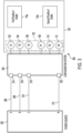
- FIG. 2 illustrates a schematic diagram of a power distribution unit 100 ("PDU 100") for evenly distributing power to one or more loads according to an example.
- the PDU 100 may be configured such that any given set of outlets can provide balanced power to one or more loads.
- the average power provided to a given outlet and/or receptacle will be approximately equal for each outlet and/or receptacle.
- the PDU 100 includes a first source contact 102, a second source contact 104, a third source contact 106, a first return contact 108, a second return contact 110, a third return contact 112, a first plurality of outlets 114a, a second plurality of outlets 114b, and a phase selection interface 132.
- the return contacts 108-112 may be coupled to a return connection (for example, a neutral or ground connection) in some examples.
- the return contacts 108-112 may be coupled to a return connection.
- the return contacts 108-112 may be coupled to a source of a phase of power.
- the return contacts 108-112 may each be coupled to a source of a respective phase of power.
- the return contacts 108-112 may be referred to herein as "return" contacts, the return contacts 108-112 may not be coupled to a return connection and may instead be coupled to a source of a phase of power in some examples.
- the first plurality of outlets 114a includes a first receptacle 116a, a second receptacle 118a, a third receptacle 116b, a fourth receptacle 118b, a fifth receptacle 116c, and a sixth receptacle 118c.
- the first receptacle 116a includes a first opening 120a, a second opening 122a, and a third opening 124a.
- the second receptacle 118a includes a first opening 126a, a second opening 128a, and a third opening 130a.
- the third receptacle 116b includes a first opening 120b, a second opening 122b, and a third opening 124b.
- the fourth receptacle 118b includes a first opening 126b, a second opening 128b, and a third opening 130b.
- the fifth receptacle 116c includes a first opening 120c, a second opening 122c, and a third opening 124c.
- the sixth receptacle 118c includes a first opening 126c, a second opening 128c, and a third opening 130c.
- the second plurality of outlets 114b includes a first receptacle 116d, a second receptacle 118d, a third receptacle 116e, a fourth receptacle 118e, a fifth receptacle 116f, and a sixth receptacle 118f.
- the first receptacle 116d includes a first opening 120d, a second opening 122d, and a third opening 124d.
- the second receptacle 118d includes a first opening 126d, a second opening 128d, and a third opening 130d.
- the third receptacle 116e includes a first opening 120e, a second opening 122e, and a third opening 124e.
- the fourth receptacle 118e includes a first opening 126e, a second opening 128e, and a third opening 130e.
- the fifth receptacle 116f includes a first opening 120f, a second opening 122f, and a third opening 124f.
- the sixth receptacle 118f includes a first opening 126f, a second opening 128f, and a third opening 130f.
- each pair of receptacles constitutes an outlet.
- the first receptacle 116a and second receptacle 118a are a first outlet
- the third receptacle 116b and fourth receptacle 118b are a second outlet
- the fifth receptacle 116c and sixth receptacle 118c are a third outlet
- the first receptacle 116d and second receptacle 118d are the fourth outlet
- the third receptacle 116e and fourth receptacle 118e are a fifth outlet
- the fifth receptacle 116f and sixth receptacle 118f are a sixth outlet.
- the first opening 120a of the first receptacle 116a is coupled to the third source contact 106 and the third opening 130a of the second receptacle 118a is coupled to the first return contact 108.
- the other outlets of the first receptacle 116a and second receptacle 118a may be coupled to ground or neutral, or may be left floating (that is, not connected to anything).
- the first opening 120b of the third receptacle 116b is coupled to the second source contact 104, and the third opening 130b of the fourth receptacle 118b is coupled to the second return contact 110.
- the other outlets of the third receptacle 116b and fourth receptacle 118b may be coupled to ground or neutral, or may be left floating (that is, not connected to anything).
- the first opening 120c of the fifth receptacle 116c is coupled to the first source contact 102, and the third opening 130c of the sixth receptacle 118c is coupled to the third return contact 112.
- the other outlets of the fifth receptacle 116c and sixth receptacle 118c may be coupled to ground or neutral, or may be left floating (that is, not connected to anything).
- the first opening 120d of the first receptacle 116d is coupled to the third source contact 106 and the third opening 130d of the second receptacle 118d is coupled to the first return contact 108.
- the other outlets of the first receptacle 116d and second receptacle 118d may be coupled to ground or neutral, or may be left floating (that is, not connected to anything).
- the first opening 120e of the third receptacle 116e is coupled to the second source contact 104, and the third opening 130e of the fourth receptacle 118e is coupled to the second return contact 110.
- the other outlets of the third receptacle 116e and fourth receptacle 118e may be coupled to ground or neutral, or may be left floating (that is, not connected to anything).
- the first opening 120f of the fifth receptacle 116f is coupled to the first source contact 102
- the third opening 130f of the sixth receptacle 118f is coupled to the second return contact third return contact 112.
- the other outlets of the fifth receptacle 116f and sixth receptacle 118f may be coupled to ground or neutral, or may be left floating (that is, not connected to anything).
- each outlet may include only a single receptacle (as opposed to more than one receptacle).
- each outlet of the first plurality of outlets 114a could have a single receptacle (for example, the first, third, and fifth receptacles 116a-c).
- the respective second openings 122a-c of those outlets could be coupled to a respective phase of power.
- the second opening 122a of the first receptacle 116a could be coupled to the first return contact 108
- the second opening 122b of the third receptacle 116b could be coupled to the second return contact 110
- the second opening 122c of the fifth receptacle 116c could be coupled to the third return contact 112.
- the first plurality of outlets 114a may be a first set of outlets for a three-phase power system
- the second plurality of outlets 114b may be a second set of outlets for a three-phase power system.
- the first plurality of outlets 114a and second plurality of outlets 114b may be outlets for a multiphase power system having less than or more than three phases of power.
- the number of outlets in each plurality of outlets 114a, 114b may be increased or decreased to be equal to a multiple of the number of phases of power in the multiphase power system.
- the source contacts 102-106 and return contacts 108-112 are part of a phase selection interface 132.
- the phase selection interface 132 may be an interface configured to receive the configuration system 16 so that the contacts 102-112 can be connected to the desired phase of input power and/or to a return connection (for example, a neutral or ground connection).
- the phase selection interface 132 may be configured to retain the configuration system 16 in a set position until the configuration system 16 is removed by a user.
- FIG. 3 illustrates a schematic diagram of a power system 200 according to an example.
- the power system 200 illustrates a power source 202 connected to a configuration system 204.
- the configuration system 204 acts as an intermediary between the power source 202 and the PDU 100 (here illustrated in part by the source and return contacts 102-112), and determines which phases of power are routed to and/or from which of the contacts 102-112.
- the configuration system 204 may be modular, and thus may be replaceable or removeable, as will be discussed in greater detail below. In various examples, the modularity of the configuration system 204 allows the single PDU 100 to provide multiple configurations of output power to connected loads.
- the PDU 100 can provide phases of power to the loads that match the phases of power available from a delta-configured PDU.
- the configuration system 204 connects the contacts 102-112 to the power source 202 such that the PDU 100 is in a wye configuration
- the PDU 100 can provide phases of power to connected loads that match the phases of power available from a wye-configured PDU.
- the configuration system 204 includes a first input 214, a second input 216, a third input 218, and a return connection 220.
- the power system 200 includes a first conductive path 206 coupling the power source 202 to the first input 214, a second conductive path 208 coupling the power source 202 to the second input 216, a third conductive path 210 coupling the power source 202 to the third input 218, and a fourth conductive path 212 coupling the power source 202 to the return connection 220.
- the power source 202 is coupled to the first conductive path 206 at a first connection, to the second conductive path 208 at a second connection, to the third conductive path 210 at a third connection, and to the fourth conductive path 212 at a fourth connection.
- the first conductive path 206 is coupled to the power source 202 at a first connection and to the first input 214 at a second connection.
- the second conductive path 208 is coupled to the power source 202 at a first connection and to the second input 216 at a second connection.
- the third conductive path 210 is coupled to the power source 202 at a first connection and to the third input 218 at a second connection.
- the fourth conductive path 212 is coupled to the power source 202 at a first connection and to the return connection 220 at a second connection.
- the configuration system 204 includes the first input 214, the second input 216, the third input 218, and the return connection 220, and may be further coupled to the first source contact 102 at a first connection, the second source contact 104 at a second connection, the third source contact 106 at a third connection, the first return contact 108 at a fourth connection, the second return contact 110 at a fifth connection, and/or the third return contact 112 at a sixth connection.
- the power source 202 may provide one or more phases of power.
- the power source 202 is illustrated as a three-phase power source, providing an "A,” “B,” and “C” phases of power to the configuration system 204, as well as having a neutral connection “N" connected to the configuration system 204.
- the "A” phase of power is provided to the configuration system 204 via the first conductive path 206 and the first input 214.
- the “B” phase of power is provided to the configuration system 204 via the second conductive path 208 and the second input 216.
- the “C” phase of power is provided to the configuration system 204 via the third conductive path 210 and the third input 218.
- the neutral line, "N” is connected to the configuration system 204 via the fourth conducting path 212 and the return connection 220.
- the power source 202 may provide the "A,” “B,” and “C” phases of power to the configuration system 204.
- the configuration system 204 then routes the phases of power to one or more of the contacts 102-112.
- the configuration system 204 can route the phases of power however desired.
- the configuration system 204 may route any phase of power to any of the source or return contacts 102-112.
- Various connections will be described in more detail with respect to FIGS. 4 and 5 .
- the configuration system 204 can facilitate any power configuration, including delta and wye configurations for three-phase power, as well as any desired configurations for one-phase, two-phase, four-phase power, and so on by providing connections and/or conducting paths between inputs (for example, the inputs 214-218), return connection(s) (for example, the return connection 220), and contacts (for example, the contacts 102-112).
- the number of conducting paths and connections for the conducting paths, as well as the number of inputs into the configuration system 204 may be increased or decreased to equal the number of phases of power.
- FIG. 4 illustrates a schematic diagram of the power system 200 in a wye configuration according to an example.
- the output voltage for each output is measured with respect to neutral (or ground).
- the return path may be through a neutral line (though wye configurations that do not have neutral lines also exist and may be implemented on the power system 200).
- the first input 214 is coupled, via the configuration system 204, to the first source contact 102.
- the second input 216 is coupled, also via the configuration system 204, to the second source contact 104.
- the third input 218 is coupled, also via the configuration system 204, to the third source contact 106.
- the return connection 220 is coupled to the first return contact 108, the second return contact 110, and the third return contact 112.
- the configuration system 204 may include conductive paths, such as conductive traces, to couple the inputs 214-218 and the return connection 220 to desired ones of the contacts 102-112.
- the routing of the conductive paths within the configuration system 204 may dictate how power provided by the power source 202 is distributed to the PDU 100.
- the configuration system 204 is modular and may be easily replaced by a different configuration system with different conductive-path routings, a designer of the power system 200 may easily change how power from the power source 202 is distributed to the PDU 100 by reconfiguring or replacing the configuration system 204.
- each of the third openings 130a-f may also be coupled to the neutral line "N" of the power source 202.
- Each of the first openings 120a, 120d of the first receptacles 116a, 116d may be coupled to the third source contact 106
- each of the first openings 120b, 120e may be coupled to the second source contact 104
- each of the first openings 120c, 120f of the fifth receptacles 116c, 116f may be coupled to the first source contact 102.
- each outlet of a given plurality of outlets 114a, 114b provides a different phase of power, with the maximum voltage differentials for each phase of power being equal to the difference between the maximum voltage differential of "A" and "N,” “B” and “N,” and/or "C” and "N.”
- FIG. 5 illustrates a schematic diagram of the power system 200 coupled in a delta configuration according to an example. In many delta configurations, no neutral connection is present. Instead, the outputs are defined by differential relationships between three phases of power.
- the configuration system 204 is configured such that first input 214 is coupled to the first source contact 102 and the second return contact 110.
- the second input 216 is coupled to the second source contact 104 and the first return contact 108.
- the third input 218 is coupled to the third source contact 106 and the third return contact 112.
- the return connection 220 may not be coupled to any source or return contact.
- the configuration system 204 may not route the return connection 220 to any contact.
- each of the first openings 120a, 120d of the first receptacles 116a, 116d may be coupled to the third source contact 106, and each of the third openings 130a, 130d of the second receptacles 118a, 118d may be coupled to the first return contact 108.
- each first outlet that is, the outlet containing the first receptacles 116a, 116d and the second receptacles 118a, 118d
- each first outlet that is, the outlet containing the first receptacles 116a, 116d and the second receptacles 118a, 118d
- each of the first openings 120b, 120e of the third receptacles 116b, 116e may be coupled to the second source contact 104, and each of the third openings 130b, 130e of the fourth receptacles 118b, 118e may be coupled to the second return contact 110.
- the second outlets that is, the outlets containing the third receptacles 116b, 116e and the fourth receptacles 118b, 118e
- each of the first openings 120c, 120f of the fifth receptacles 116c, 116f may be coupled to the first source contact 102, and each of the third openings 130c, 130f of the sixth receptacles 118c, 118f may be coupled to the third return contact 112.
- the third outlets that is, the outlets containing the fifth receptacles 116c, 116f and the sixth receptacles 118c, 118f
- the third outlets that is, the outlets containing the fifth receptacles 116c, 116f and the sixth receptacles 118c, 118f
- FIG. 5 illustrates a process 300 of managing the configuration of the PDU 100.
- a user or other entity provides a PDU 100 for use in a location, such as a datacenter, a server room, a server rack, or any other location where the provision of electricity is desirable or wanted.
- the process 300 then continues to act 304.
- the user or a controller determines the desired configuration of the PDU 100. For example, the user may determine that a delta or wye configuration is desired, or that some other configuration for multiphase power is desired. Once the desired configuration is determined by the user, the process 300 continues to act 306.
- act 306 determines if the configuration system 16 is set to configure the PDU 100 such that the PDU 100 will be in the desired configuration. For example, if the desired configuration is a delta configuration, act 306 may include determining whether the configuration system 16 has a topology to configure the PDU 100 in a delta configuration (for example, as illustrated in FIG. 5 ). If the configuration system 16 does not have a desired topology (306 NO), the process 300 may continue to act 308. If the configuration system 16 has a desired topology (306 YES), then the process 300 may continue to act 310.
- the user or controller may alter the configuration system 16. Altering the configuration system 16 may include changing the conductive paths within the configuration system 16, and/or may include replacing the configuration system 16 with a different configuration system with a different topology. If the configuration system 16 is modularly connected to the PDU 100 (that is, interchangeable with respect to the PDU 100), the configuration system 16 may be replaced with another configuration system having a desired configuration. For example, the configuration system 16 may be removed from a slot, bracket, cradle, pin, or any other holder that allows the configuration system 16 to be interfaced with the PDU 100.
- the configuration system 16 may adjust its conductive paths as needed and/or desired to cause the configuration system 16 to have a desired topology. The process 300 may then continue to act 310.
- the PDU 100 may be placed into operation.
- the PDU 100 may be coupled to one or more loads via the outlets 114a, 114b.
- the PDU 100 may then provide power to the loads pursuant to the configuration set by the configuration system 204.
- the process 300 may then continue to act 312.
- the user or controller may determine whether the configuration of the PDU 100 should be changed. For example, the PDU 100 may have been providing power to loads requiring a first power configuration (for example, according to a delta configuration), but now may require a second power configuration (for example, according to a wye configuration). If the configuration of the PDU 100 does not need to be changed (312 NO), the process 300 may return to act 310. If the configuration of the PDU 100 should be changed (312 YES), the process 300 may return to act 304.
- the configuration systems 16, 204 may be implemented according to a variety of methods and systems.
- the configuration system 16, 204 may be a printed circuit board (PCB) configured to be modular (that is, to be installable in and/or removeable from the power distribution system 14 and/or the PDUs 18, 100).
- the configuration systems 16, 204 may include electrical traces (for example, lines of conductive material) that connect a contact to an input to receive one of the phases of power.
- the configuration systems 16, 204 may include a switching circuit, for example, a circuit containing switching devices (such as transistors) that allow the configuration systems 16, 204 to selectively connect switches to different inputs to receive different phases of power.
- the configuration systems 16, 204 may be controllable by a controller or other control circuitry (for example, configuration registers that can be used to set how the configuration systems 16, 204 operate and/or connect contacts to inputs to receive phases of power).
- the configuration systems 16, 204 may be changed based on the needs of the loads 20 and/or power source 12. For example, in one situation, the PDUs 18, 100 may be required to provide power according to a delta configuration. Accordingly, the configuration systems 16, 204 may be provided to configure the PDU 18, 100 to provide power according to a delta configuration. Later, the loads 20 may benefit from or require wye-configuration power. Accordingly, the configuration systems 16, 204 may be reconfigured such that the PDUs 18, 100 provide power according to a wye configuration, or the configuration systems 16, 204 may be removed and replaced with a configuration system that configure the PDU 18, 100 to provide power according to a wye configuration. All of this may be accomplished without changing the power source 12 or the PDUs 18, 100.
- third openings 124a-f and/or first openings 126a-f may be coupled to a ground connection.
- the ground connection may be an integrated part of the PDU 100 (that is, the ground connection may not be determined by the phase selection interface 132 or configuration system 16, 204.
- controllers may execute various operations discussed above. Using data stored in associated memory and/or storage, the controller may also execute one or more instructions stored on one or more non-transitory computer-readable media, which the controller may include and/or be coupled to, that may result in manipulated data.
- the controller may include one or more processors or other types of controllers.
- the controller is or includes at least one processor.
- the controller performs at least a portion of the operations discussed above using an application-specific integrated circuit tailored to perform particular operations in addition to, or in lieu of, a general-purpose processor.
- examples in accordance with the present disclosure may perform the operations described herein using many specific combinations of hardware and software and the disclosure is not limited to any particular combination of hardware and software components.
- Examples of the disclosure may include a computer-program product configured to execute methods, processes, and/or operations discussed above.
- the computer-program product may be, or include, one or more controllers and/or processors configured to execute instructions to perform methods, processes, and/or operations discussed above.
- a power distribution unit comprising:
- Clause 2 The PDU of clause 1 wherein the configuration system is configured to conductively link at least one source contact to at least one input configured to provide a phase of input power.
- each additional outlet having a supply opening coupled to a source contact of the phase selection interface and a return opening coupled to a return contact of the phase selection interface.
- Clause 6 The PDU of clause 1 further comprising one or more additional outlets in addition to the first outlet and the second outlet, wherein a total number of outlets of the PDU equals an integer multiple of a total number of phases of input power received by the PDU.
- each outlet comprises a first receptacle and a second receptacle, each respective first receptacle including a respective supply opening, and each respective second receptacle including a respective return opening.
- each receptacle includes three openings.
- a method of routing power through a power distribution unit comprising:
- Clause 11 The method of clause 10 wherein the configuration system is further configured to link at least one of the first source contact, the first return contact, the second source contact, and the second return contact to a second input configured to provide a second phase of input power.
- coupling the configuration system to the interface includes providing one or more modular printed circuit boards (PCBs) compatible with the interface, the one or more modular PCBs containing a plurality of conductive traces configured to link one or more of the first source contact, the first return contact, the second source contact, and the second return contact to the first phase of input power.
- PCBs printed circuit boards
- Clause 13 The method of clause 10 further comprising providing at least one source contact for each phase of input power, at least one return contact for each phase of input power, and at least one outlet for each phase of input power.
- Clause 14 The method of clause 10 wherein a number of outlets of the PDU is an integer multiple of a number of phases of input power received by the PDU.
- a system for distributing multiphase power in a balanced manner comprising:
- Clause 16 The system of clause 15 further comprising the configuration system, the configuration system being configured to link each contact to at least one input configured to provide at least one phase of input power.
- Clause 17 The system of clause 15 further comprising a second plurality of outlets coupled to at least two contacts of the plurality of contacts.
- Clause 18 The system of clause 17 wherein the first plurality of outlets and the second plurality of outlets include an equal number of outlets.
- Clause 19 The system of clause 15 wherein the first plurality of outlets includes at least one outlet for each contact of the first group of contacts and wherein each respective outlet of the first plurality of outlets is coupled to a respective contact of the first group of contacts and a respective contact of the second plurality of contacts.
- each outlet of the first plurality of outlets includes at least two receptacles, and each receptacle includes at least one opening.
Landscapes
- Engineering & Computer Science (AREA)
- Power Engineering (AREA)
- Theoretical Computer Science (AREA)
- Microelectronics & Electronic Packaging (AREA)
- Human Computer Interaction (AREA)
- Physics & Mathematics (AREA)
- General Engineering & Computer Science (AREA)
- General Physics & Mathematics (AREA)
- Supply And Distribution Of Alternating Current (AREA)
- Details Of Connecting Devices For Male And Female Coupling (AREA)
Abstract
According to at least one aspect of the present disclosure a power distribution unit (PDU) is provided, the PDU comprising: a phase selection interface having: a first source contact configured to couple to a configuration system, a first return contact configured to couple to the configuration system, a second source contact configured to couple to the configuration system, and a second return contact configured to couple to the configuration system; a first outlet having: a first supply opening coupled to the first source contact, and a first return opening coupled to the first return contact; and a second outlet having: a second supply opening coupled to the second source contact, and a second return opening coupled to the second return contact.
Description
- At least one example in accordance with the present disclosure relates generally to power-distribution systems.
- Power-distribution units, such as power strips, may provide power to one or more loads at a time. Power distribution units may have additional functionality, such as monitoring hardware and software, ethernet connectivity to facilitate remote monitoring of power conditions, and so forth.
- Various aspects of at least one embodiment are discussed below with reference to the accompanying figures, which are not intended to be drawn to scale. The figures are included to provide an illustration and a further understanding of the various aspects and embodiments, and are incorporated in and constitute a part of this specification, but are not intended as a definition of the limits of any particular embodiment. The drawings, together with the remainder of the specification, serve to explain principles and operations of the described and claimed aspects and embodiments. In the figures, each identical or nearly identical component that is illustrated in various figures is represented by a like numeral. For purposes of clarity, not every component may be labeled in every figure. In the figures:
-
FIG. 1 illustrates a block diagram of a power system according to an example; -
FIG. 2 illustrates a schematic diagram of a power distribution unit according to an example; -
FIG. 3 illustrates a schematic diagram of a power system according to an example; -
FIG. 4 illustrates a schematic diagram of a power system according to an example; -
FIG. 5 illustrates a schematic diagram of a power system according to an example; and -
FIG. 6 illustrates a process for managing a power distribution unit according to an example. - Examples of the methods and systems discussed herein are not limited in application to the details of construction and the arrangement of components set forth in the following description or illustrated in the accompanying drawings. The methods and systems are capable of implementation in other embodiments and of being practiced or of being carried out in various ways. Examples of specific implementations are provided herein for illustrative purposes only and are not intended to be limiting. In particular, acts, components, elements and features discussed in connection with any one or more examples are not intended to be excluded from a similar role in any other examples.
- Also, the phraseology and terminology used herein is for the purpose of description and should not be regarded as limiting. Any references to examples, embodiments, components, elements or acts of the systems and methods herein referred to in the singular may also embrace embodiments including a plurality, and any references in plural to any embodiment, component, element or act herein may also embrace embodiments including only a singularity. References in the singular or plural form are not intended to limit the presently disclosed systems or methods, their components, acts, or elements. The use herein of "including," "comprising," "having," "containing," "involving," and variations thereof is meant to encompass the items listed thereafter and equivalents thereof as well as additional items.
- References to "or" may be construed as inclusive so that any terms described using "or" may indicate any of a single, more than one, and all of the described terms. In addition, in the event of inconsistent usages of terms between this document and documents incorporated herein by reference, the term usage in the incorporated features is supplementary to that of this document; for irreconcilable differences, the term usage in this document controls.
- Power-distribution units ("PDUs") may receive power from a power source (such as single- or multi-phase power systems) and can provide the power to one or more loads. PDUs may be designed such that the loads draw power in a balanced manner in some examples. For example, in a three-phase power system, the PDU may be designed to distribute the first phase of power to a first load, the second phase of power to a second load, and the third phase of power to a third load. The outlets of the PDU may be further configured to provide the load balancing, such that no particular phase of power is under an unbalanced level of strain or loading.
-
FIG. 1 illustrates a block diagram of apower system 10 according to an example. Thepower system 10 may evenly distribute power to one or more loads. In various examples, thepower system 10 may be configurable. For example, thepower system 10 may be modified to provide power according to different schemes (for example, with respect to three-phase power, delta and/or wye configurations). - The
power system 10 includes apower source 12, apower distribution system 14 including aconfiguration system 16 and a power distribution unit 18 ("PDU 18"), and one or more loads 20 ("loads 20"). Thepower source 12 is coupled to thepower distribution system 14 via theconfiguration system 16. Theconfiguration system 16 is coupled to thepower source 12 at a first connection and to thePDU 18 at a second connection. ThePDU 18 is coupled to theconfiguration system 16 at a first connection and to theloads 20 at one or more second connections. Theloads 20 are coupled to thepower distribution system 14 via thePDU 18. In various examples, thePDU 18 is configured to distribute power evenly to theloads 20. For example, the PDU 18 may include multiple sets of several outlets. Each set of outlets may include at least one outlet that provides the same amount of power as a corresponding outlet in all of the other sets of outlets. For example, if the PDU 18 includes five sets of three outlets each, at least one of the three outlets in each of the five sets may provide the same amount of power as one another. In this example, each set of outlets contains at least one outlet that provides the same power as at least one corresponding outlet in each other set of outlets. - In some examples, the
PDU 18 has a topology that accommodates multiple sets of outlets. Each set of outlets may contain one or more outlets. For example, the PDU 18 could have two sets of three outlets, three sets of four outlets, five sets of one outlet, and so forth. For any set of outlets, the first outlet in the set may be coupled to the same source and return path as the first outlet in each other set. The second outlet in the set may be coupled to the same source and return path as the second outlet in each other set, and so forth for every additional outlet. - In various examples, the number of outlets in each set may be an integer multiple of the number of phases of power provided by the
power source 12. Thus, if thepower source 12 provides two-phase power, the PDU could have two outlets (that is, one set), four outlets (that is, two sets), six outlets (that is, three sets), or another multiple of two worth of outlets, where each first outlet in each set is coupled to the same respective source and return path, and each second outlet in each set is coupled to the same respective source and return path. In this way, the user of thePDU 18 can be assured that any load plugged into the first outlet in any given set of outlets receives the same power as any load plugged into another first outlet in any given set of outlets. The same is true for the other outlets for each set of outlets. - The
configuration system 16 is configured to route different phases of power to different outlets in thePDU 18. Accordingly, theconfiguration system 16 may determine which outlets output which phases of power. Theconfiguration system 16 may also determine the relative voltages between the source and return paths for a given outlet, as discussed in greater detail with respect toFIGS. 3-5 . Theconfiguration system 16 may also be modular and/or configurable (that is, theconfiguration system 16 may be removed and/or replaced without damaging thePDU 18, such that theconfiguration system 16 may be considered "plug-and-play"), such that the connections provided by theconfiguration source 16 between thePDU 18 and thepower source 12 may be changed -
FIG. 2 illustrates a schematic diagram of a power distribution unit 100 ("PDU 100") for evenly distributing power to one or more loads according to an example. The PDU 100 may be configured such that any given set of outlets can provide balanced power to one or more loads. In general, for any phase configuration of the power source (one-phase, two-phase, three-phase, and so forth) the average power provided to a given outlet and/or receptacle will be approximately equal for each outlet and/or receptacle. - The
PDU 100 includes afirst source contact 102, asecond source contact 104, athird source contact 106, afirst return contact 108, asecond return contact 110, athird return contact 112, a first plurality ofoutlets 114a, a second plurality ofoutlets 114b, and aphase selection interface 132. As discussed in greater detail below, the return contacts 108-112 may be coupled to a return connection (for example, a neutral or ground connection) in some examples. For example, in a configuration based on a wye topology, the return contacts 108-112 may be coupled to a return connection. In other examples, the return contacts 108-112 may be coupled to a source of a phase of power. For example, in a configuration based on a delta topology, the return contacts 108-112 may each be coupled to a source of a respective phase of power. Thus, while the return contacts 108-112 may be referred to herein as "return" contacts, the return contacts 108-112 may not be coupled to a return connection and may instead be coupled to a source of a phase of power in some examples. - The first plurality of
outlets 114a includes afirst receptacle 116a, asecond receptacle 118a, athird receptacle 116b, afourth receptacle 118b, afifth receptacle 116c, and asixth receptacle 118c. Thefirst receptacle 116a includes afirst opening 120a, asecond opening 122a, and athird opening 124a. Thesecond receptacle 118a includes afirst opening 126a, asecond opening 128a, and athird opening 130a. Thethird receptacle 116b includes afirst opening 120b, asecond opening 122b, and athird opening 124b. Thefourth receptacle 118b includes afirst opening 126b, asecond opening 128b, and athird opening 130b. Thefifth receptacle 116c includes afirst opening 120c, asecond opening 122c, and a third opening 124c. Thesixth receptacle 118c includes afirst opening 126c, asecond opening 128c, and athird opening 130c. - The second plurality of
outlets 114b includes afirst receptacle 116d, asecond receptacle 118d, a third receptacle 116e, afourth receptacle 118e, afifth receptacle 116f, and asixth receptacle 118f. Thefirst receptacle 116d includes afirst opening 120d, asecond opening 122d, and athird opening 124d. Thesecond receptacle 118d includes afirst opening 126d, asecond opening 128d, and athird opening 130d. The third receptacle 116e includes afirst opening 120e, asecond opening 122e, and a third opening 124e. Thefourth receptacle 118e includes afirst opening 126e, asecond opening 128e, and athird opening 130e. Thefifth receptacle 116f includes afirst opening 120f, asecond opening 122f, and athird opening 124f. Thesixth receptacle 118f includes afirst opening 126f, a second opening 128f, and a third opening 130f. - In the example of
FIG. 1 , each pair of receptacles constitutes an outlet. Thus, thefirst receptacle 116a andsecond receptacle 118a are a first outlet, thethird receptacle 116b andfourth receptacle 118b are a second outlet, thefifth receptacle 116c andsixth receptacle 118c are a third outlet, thefirst receptacle 116d andsecond receptacle 118d are the fourth outlet, the third receptacle 116e andfourth receptacle 118e are a fifth outlet, and thefifth receptacle 116f andsixth receptacle 118f are a sixth outlet. - With respect to the first plurality of
outlets 114a, thefirst opening 120a of thefirst receptacle 116a is coupled to thethird source contact 106 and thethird opening 130a of thesecond receptacle 118a is coupled to thefirst return contact 108. The other outlets of thefirst receptacle 116a andsecond receptacle 118a may be coupled to ground or neutral, or may be left floating (that is, not connected to anything). - With respect to the first plurality of
outlets 114a, thefirst opening 120b of thethird receptacle 116b is coupled to thesecond source contact 104, and thethird opening 130b of thefourth receptacle 118b is coupled to thesecond return contact 110. The other outlets of thethird receptacle 116b andfourth receptacle 118b may be coupled to ground or neutral, or may be left floating (that is, not connected to anything). - With respect to the first plurality of
outlets 114a, thefirst opening 120c of thefifth receptacle 116c is coupled to thefirst source contact 102, and thethird opening 130c of thesixth receptacle 118c is coupled to thethird return contact 112. The other outlets of thefifth receptacle 116c andsixth receptacle 118c may be coupled to ground or neutral, or may be left floating (that is, not connected to anything). - With respect to the second plurality of
outlets 114b, thefirst opening 120d of thefirst receptacle 116d is coupled to thethird source contact 106 and thethird opening 130d of thesecond receptacle 118d is coupled to thefirst return contact 108. The other outlets of thefirst receptacle 116d andsecond receptacle 118d may be coupled to ground or neutral, or may be left floating (that is, not connected to anything). - With respect to the second plurality of
outlets 114b, thefirst opening 120e of the third receptacle 116e is coupled to thesecond source contact 104, and thethird opening 130e of thefourth receptacle 118e is coupled to thesecond return contact 110. The other outlets of the third receptacle 116e andfourth receptacle 118e may be coupled to ground or neutral, or may be left floating (that is, not connected to anything). - With respect to the second plurality of
outlets 114b, thefirst opening 120f of thefifth receptacle 116f is coupled to thefirst source contact 102, and the third opening 130f of thesixth receptacle 118f is coupled to the second return contactthird return contact 112. The other outlets of thefifth receptacle 116f andsixth receptacle 118f may be coupled to ground or neutral, or may be left floating (that is, not connected to anything). - In some examples, each outlet may include only a single receptacle (as opposed to more than one receptacle). For example, each outlet of the first plurality of
outlets 114a could have a single receptacle (for example, the first, third, andfifth receptacles 116a-c). In such cases, the respectivesecond openings 122a-c of those outlets could be coupled to a respective phase of power. For example, thesecond opening 122a of thefirst receptacle 116a could be coupled to thefirst return contact 108, thesecond opening 122b of thethird receptacle 116b could be coupled to thesecond return contact 110, and thesecond opening 122c of thefifth receptacle 116c could be coupled to thethird return contact 112. - With respect to
FIG. 1 , the first plurality ofoutlets 114a may be a first set of outlets for a three-phase power system, and the second plurality ofoutlets 114b may be a second set of outlets for a three-phase power system. In some examples, the first plurality ofoutlets 114a and second plurality ofoutlets 114b may be outlets for a multiphase power system having less than or more than three phases of power. In such examples, the number of outlets in each plurality ofoutlets - In some examples, the source contacts 102-106 and return contacts 108-112 are part of a
phase selection interface 132. Thephase selection interface 132 may be an interface configured to receive theconfiguration system 16 so that the contacts 102-112 can be connected to the desired phase of input power and/or to a return connection (for example, a neutral or ground connection). In some examples, thephase selection interface 132 may be configured to retain theconfiguration system 16 in a set position until theconfiguration system 16 is removed by a user. -
FIG. 3 illustrates a schematic diagram of apower system 200 according to an example. Thepower system 200 illustrates apower source 202 connected to aconfiguration system 204. Theconfiguration system 204 acts as an intermediary between thepower source 202 and the PDU 100 (here illustrated in part by the source and return contacts 102-112), and determines which phases of power are routed to and/or from which of the contacts 102-112. Theconfiguration system 204 may be modular, and thus may be replaceable or removeable, as will be discussed in greater detail below. In various examples, the modularity of theconfiguration system 204 allows thesingle PDU 100 to provide multiple configurations of output power to connected loads. For example, if theconfiguration system 204 connects the contacts 102-112 to thepower source 202 such that thePDU 100 is in a delta configuration, thePDU 100 can provide phases of power to the loads that match the phases of power available from a delta-configured PDU. Likewise, if theconfiguration system 204 connects the contacts 102-112 to thepower source 202 such that thePDU 100 is in a wye configuration, thePDU 100 can provide phases of power to connected loads that match the phases of power available from a wye-configured PDU. - The
configuration system 204 includes afirst input 214, asecond input 216, athird input 218, and areturn connection 220. Thepower system 200 includes a firstconductive path 206 coupling thepower source 202 to thefirst input 214, a secondconductive path 208 coupling thepower source 202 to thesecond input 216, a thirdconductive path 210 coupling thepower source 202 to thethird input 218, and a fourthconductive path 212 coupling thepower source 202 to thereturn connection 220. - The
power source 202 is coupled to the firstconductive path 206 at a first connection, to the secondconductive path 208 at a second connection, to the thirdconductive path 210 at a third connection, and to the fourthconductive path 212 at a fourth connection. The firstconductive path 206 is coupled to thepower source 202 at a first connection and to thefirst input 214 at a second connection. The secondconductive path 208 is coupled to thepower source 202 at a first connection and to thesecond input 216 at a second connection. The thirdconductive path 210 is coupled to thepower source 202 at a first connection and to thethird input 218 at a second connection. The fourthconductive path 212 is coupled to thepower source 202 at a first connection and to thereturn connection 220 at a second connection. Theconfiguration system 204 includes thefirst input 214, thesecond input 216, thethird input 218, and thereturn connection 220, and may be further coupled to thefirst source contact 102 at a first connection, thesecond source contact 104 at a second connection, thethird source contact 106 at a third connection, thefirst return contact 108 at a fourth connection, thesecond return contact 110 at a fifth connection, and/or thethird return contact 112 at a sixth connection. - The
power source 202 may provide one or more phases of power. InFIG. 3 , thepower source 202 is illustrated as a three-phase power source, providing an "A," "B," and "C" phases of power to theconfiguration system 204, as well as having a neutral connection "N" connected to theconfiguration system 204. The "A" phase of power is provided to theconfiguration system 204 via the firstconductive path 206 and thefirst input 214. The "B" phase of power is provided to theconfiguration system 204 via the secondconductive path 208 and thesecond input 216. The "C" phase of power is provided to theconfiguration system 204 via the thirdconductive path 210 and thethird input 218. The neutral line, "N," is connected to theconfiguration system 204 via thefourth conducting path 212 and thereturn connection 220. - When the
power source 202 is providing power, thepower source 202 may provide the "A," "B," and "C" phases of power to theconfiguration system 204. Theconfiguration system 204 then routes the phases of power to one or more of the contacts 102-112. Theconfiguration system 204 can route the phases of power however desired. For example, theconfiguration system 204 may route any phase of power to any of the source or return contacts 102-112. Various connections will be described in more detail with respect toFIGS. 4 and5 . Theconfiguration system 204 can facilitate any power configuration, including delta and wye configurations for three-phase power, as well as any desired configurations for one-phase, two-phase, four-phase power, and so on by providing connections and/or conducting paths between inputs (for example, the inputs 214-218), return connection(s) (for example, the return connection 220), and contacts (for example, the contacts 102-112). - In some examples, where the power system includes fewer than or more than three phases of power, the number of conducting paths and connections for the conducting paths, as well as the number of inputs into the
configuration system 204, may be increased or decreased to equal the number of phases of power. -
FIG. 4 illustrates a schematic diagram of thepower system 200 in a wye configuration according to an example. In many wye configurations, the output voltage for each output is measured with respect to neutral (or ground). Thus, in many wye configurations, the return path may be through a neutral line (though wye configurations that do not have neutral lines also exist and may be implemented on the power system 200). - In
FIG. 4 , thefirst input 214 is coupled, via theconfiguration system 204, to thefirst source contact 102. Thesecond input 216 is coupled, also via theconfiguration system 204, to thesecond source contact 104. Thethird input 218 is coupled, also via theconfiguration system 204, to thethird source contact 106. Thereturn connection 220 is coupled to thefirst return contact 108, thesecond return contact 110, and thethird return contact 112. - In various examples, the
configuration system 204 may include conductive paths, such as conductive traces, to couple the inputs 214-218 and thereturn connection 220 to desired ones of the contacts 102-112. Thus, the routing of the conductive paths within theconfiguration system 204 may dictate how power provided by thepower source 202 is distributed to thePDU 100. Because theconfiguration system 204 is modular and may be easily replaced by a different configuration system with different conductive-path routings, a designer of thepower system 200 may easily change how power from thepower source 202 is distributed to thePDU 100 by reconfiguring or replacing theconfiguration system 204. - Returning to
FIG. 2 with reference to the topology of theconfiguration system 204 illustrated inFIG. 4 , because each return contact 108-112 is coupled to the neutral line "N" of thepower source 202 via theconfiguration system 204, each of thethird openings 130a-f may also be coupled to the neutral line "N" of thepower source 202. Each of thefirst openings first receptacles third source contact 106, each of thefirst openings second source contact 104, and each of thefirst openings fifth receptacles first source contact 102. As a result, the first outlet of each plurality ofoutlets outlets outlets outlets -
FIG. 5 illustrates a schematic diagram of thepower system 200 coupled in a delta configuration according to an example. In many delta configurations, no neutral connection is present. Instead, the outputs are defined by differential relationships between three phases of power. - In
FIG. 5 , theconfiguration system 204 is configured such thatfirst input 214 is coupled to thefirst source contact 102 and thesecond return contact 110. Thesecond input 216 is coupled to thesecond source contact 104 and thefirst return contact 108. Thethird input 218 is coupled to thethird source contact 106 and thethird return contact 112. Thereturn connection 220 may not be coupled to any source or return contact. For example, theconfiguration system 204 may not route thereturn connection 220 to any contact. - Returning to
FIG. 2 with reference to the topology of theconfiguration system 204 illustrated inFIG. 5 , each of thefirst openings first receptacles third source contact 106, and each of thethird openings second receptacles first return contact 108. Accordingly, each first outlet (that is, the outlet containing thefirst receptacles second receptacles - Similarly, each of the
first openings third receptacles 116b, 116e may be coupled to thesecond source contact 104, and each of thethird openings fourth receptacles second return contact 110. As a result, the second outlets (that is, the outlets containing thethird receptacles 116b, 116e and thefourth receptacles - Likewise, each of the
first openings fifth receptacles first source contact 102, and each of thethird openings 130c, 130f of thesixth receptacles third return contact 112. As a result, the third outlets (that is, the outlets containing thefifth receptacles sixth receptacles -
FIG. 5 illustrates aprocess 300 of managing the configuration of thePDU 100. - At
act 302, a user or other entity provides aPDU 100 for use in a location, such as a datacenter, a server room, a server rack, or any other location where the provision of electricity is desirable or wanted. Theprocess 300 then continues to act 304. - At
act 304, the user or a controller determines the desired configuration of thePDU 100. For example, the user may determine that a delta or wye configuration is desired, or that some other configuration for multiphase power is desired. Once the desired configuration is determined by the user, theprocess 300 continues to act 306. - At
act 306, the user or a controller determines if theconfiguration system 16 is set to configure thePDU 100 such that thePDU 100 will be in the desired configuration. For example, if the desired configuration is a delta configuration, act 306 may include determining whether theconfiguration system 16 has a topology to configure thePDU 100 in a delta configuration (for example, as illustrated inFIG. 5 ). If theconfiguration system 16 does not have a desired topology (306 NO), theprocess 300 may continue to act 308. If theconfiguration system 16 has a desired topology (306 YES), then theprocess 300 may continue to act 310. - At
act 308, the user or controller may alter theconfiguration system 16. Altering theconfiguration system 16 may include changing the conductive paths within theconfiguration system 16, and/or may include replacing theconfiguration system 16 with a different configuration system with a different topology. If theconfiguration system 16 is modularly connected to the PDU 100 (that is, interchangeable with respect to the PDU 100), theconfiguration system 16 may be replaced with another configuration system having a desired configuration. For example, theconfiguration system 16 may be removed from a slot, bracket, cradle, pin, or any other holder that allows theconfiguration system 16 to be interfaced with thePDU 100. If theconfiguration system 16 includes a circuit, controller, or other device that can control the configuration of thePDU 100 without being removed, theconfiguration system 16 may adjust its conductive paths as needed and/or desired to cause theconfiguration system 16 to have a desired topology. Theprocess 300 may then continue to act 310. - At
act 310, thePDU 100 may be placed into operation. For example, thePDU 100 may be coupled to one or more loads via theoutlets PDU 100 may then provide power to the loads pursuant to the configuration set by theconfiguration system 204. Theprocess 300 may then continue to act 312. - At
act 312, the user or controller may determine whether the configuration of thePDU 100 should be changed. For example, thePDU 100 may have been providing power to loads requiring a first power configuration (for example, according to a delta configuration), but now may require a second power configuration (for example, according to a wye configuration). If the configuration of thePDU 100 does not need to be changed (312 NO), theprocess 300 may return to act 310. If the configuration of thePDU 100 should be changed (312 YES), theprocess 300 may return to act 304. - The
configuration systems configuration system power distribution system 14 and/or thePDUs 18, 100). As a PCB, theconfiguration systems configuration systems configuration systems configuration systems configuration systems - In some examples, the
configuration systems loads 20 and/orpower source 12. For example, in one situation, thePDUs configuration systems PDU loads 20 may benefit from or require wye-configuration power. Accordingly, theconfiguration systems PDUs configuration systems PDU power source 12 or thePDUs - With respect to the foregoing, in some examples
third openings 124a-f and/orfirst openings 126a-f may be coupled to a ground connection. The ground connection may be an integrated part of the PDU 100 (that is, the ground connection may not be determined by thephase selection interface 132 orconfiguration system - Various controllers may execute various operations discussed above. Using data stored in associated memory and/or storage, the controller may also execute one or more instructions stored on one or more non-transitory computer-readable media, which the controller may include and/or be coupled to, that may result in manipulated data. In some examples, the controller may include one or more processors or other types of controllers. In one example, the controller is or includes at least one processor. In another example, the controller performs at least a portion of the operations discussed above using an application-specific integrated circuit tailored to perform particular operations in addition to, or in lieu of, a general-purpose processor. As illustrated by these examples, examples in accordance with the present disclosure may perform the operations described herein using many specific combinations of hardware and software and the disclosure is not limited to any particular combination of hardware and software components. Examples of the disclosure may include a computer-program product configured to execute methods, processes, and/or operations discussed above. The computer-program product may be, or include, one or more controllers and/or processors configured to execute instructions to perform methods, processes, and/or operations discussed above.
- Further examples are provided in the following clauses.
-
Clause 1. A power distribution unit (PDU) comprising: - a phase selection interface having:
- a first source contact configured to couple to a configuration system,
- a first return contact configured to couple to the configuration system,
- a second source contact configured to couple to the configuration system, and
- a second return contact configured to couple to the configuration system;
- a first outlet having:
- a first supply opening coupled to the first source contact, and
- a first return opening coupled to the first return contact; and
- a second outlet having:
- a second supply opening coupled to the second source contact, and
- a second return opening coupled to the second return contact.
-
Clause 2. The PDU ofclause 1 wherein the configuration system is configured to conductively link at least one source contact to at least one input configured to provide a phase of input power. -
Clause 3. The PDU ofclause 1 wherein the configuration system is configured to conductively link at least one return contact to at least one input configured to provide a phase of input power. - Clause 4. The PDU of
clause 1 wherein the configuration system is configured to conductively link at least one source contact or at least one return contact to a neutral or ground node. - Clause 5. The PDU of
clause 1 further comprising one or more additional outlets, each additional outlet having a supply opening coupled to a source contact of the phase selection interface and a return opening coupled to a return contact of the phase selection interface. - Clause 6. The PDU of
clause 1 further comprising one or more additional outlets in addition to the first outlet and the second outlet, wherein a total number of outlets of the PDU equals an integer multiple of a total number of phases of input power received by the PDU. - Clause 7. The PDU of clause 6 wherein the total number of phases of input power is three and the total number of outlets of the PDU is a multiple of three.
- Clause 8. The PDU of
clause 1 wherein each outlet comprises a first receptacle and a second receptacle, each respective first receptacle including a respective supply opening, and each respective second receptacle including a respective return opening. - Clause 9. The PDU of clause 8 wherein each receptacle includes three openings.
-
Clause 10. A method of routing power through a power distribution unit (PDU) comprising: - providing a first source contact coupled to a first supply opening of a first outlet of the PDU;
- providing a first return contact coupled to a first return opening of the first outlet;
- providing a second source contact coupled to a second supply opening of a second outlet of the PDU;
- providing a second return contact coupled to a second return opening of the second outlet; and
- providing an interface containing the first source contact, the first return contact, the second source contact, and the second return contact, the interface being configured to be coupled to a configuration system configured to link at least one of the first source contact, the first return contact, the second source contact, and the second return contact to an input configured to provide a first phase of input power.
- Clause 11. The method of
clause 10 wherein the configuration system is further configured to link at least one of the first source contact, the first return contact, the second source contact, and the second return contact to a second input configured to provide a second phase of input power. -
Clause 12. The method ofclause 10 wherein coupling the configuration system to the interface includes providing one or more modular printed circuit boards (PCBs) compatible with the interface, the one or more modular PCBs containing a plurality of conductive traces configured to link one or more of the first source contact, the first return contact, the second source contact, and the second return contact to the first phase of input power. - Clause 13. The method of
clause 10 further comprising providing at least one source contact for each phase of input power, at least one return contact for each phase of input power, and at least one outlet for each phase of input power. -
Clause 14. The method ofclause 10 wherein a number of outlets of the PDU is an integer multiple of a number of phases of input power received by the PDU. - Clause 15. A system for distributing multiphase power in a balanced manner, the system comprising:
- a plurality of contacts configured to be coupled to a multiphase power source, the plurality of contacts including a first group of one or more contacts and a second group of one or more contacts;
- a first plurality of outlets coupled to at least two contacts of the plurality of contacts;
- an interface coupled to the plurality of contacts and configured to be coupled to a configuration system selectively couplable to the contacts of the plurality of contacts.
-
Clause 16. The system of clause 15 further comprising the configuration system, the configuration system being configured to link each contact to at least one input configured to provide at least one phase of input power. - Clause 17. The system of clause 15 further comprising a second plurality of outlets coupled to at least two contacts of the plurality of contacts.
-
Clause 18. The system of clause 17 wherein the first plurality of outlets and the second plurality of outlets include an equal number of outlets. - Clause 19. The system of clause 15 wherein the first plurality of outlets includes at least one outlet for each contact of the first group of contacts and wherein each respective outlet of the first plurality of outlets is coupled to a respective contact of the first group of contacts and a respective contact of the second plurality of contacts.
-
Clause 20. The system of clause 15 wherein each outlet of the first plurality of outlets includes at least two receptacles, and each receptacle includes at least one opening. - Having thus described several aspects of at least one embodiment, it is to be appreciated various alterations, modifications, and improvements will readily occur to those skilled in the art. Such alterations, modifications, and improvements are intended to be part of, and within the scope of, this disclosure. Accordingly, the foregoing description and drawings are by way of example only.
Claims (15)
- A power distribution unit (PDU) comprising:a phase selection interface having:a first source contact configured to couple to a configuration system,a first return contact configured to couple to the configuration system,a second source contact configured to couple to the configuration system, anda second return contact configured to couple to the configuration system;a first outlet having:a first supply opening coupled to the first source contact, anda first return opening coupled to the first return contact; anda second outlet having:a second supply opening coupled to the second source contact, anda second return opening coupled to the second return contact.
- The PDU of claim 1, wherein the configuration system is configured to conductively link at least one source contact to at least one input configured to provide a phase of input power.
- The PDU of claims 1 or 2, wherein the configuration system is configured to conductively link at least one return contact to at least one input configured to provide a phase of input power.
- The PDU of any of the above claims, wherein the configuration system is configured to conductively link at least one source contact or at least one return contact to a neutral or ground node.
- The PDU of any of the above claims, further comprising one or more additional outlets, each additional outlet having a supply opening coupled to a source contact of the phase selection interface and a return opening coupled to a return contact of the phase selection interface.
- The PDU of any of the above claims, further comprising one or more additional outlets in addition to the first outlet and the second outlet, wherein a total number of outlets of the PDU equals an integer multiple of a total number of phases of input power received by the PDU.
- The PDU of claim 6, wherein the total number of phases of input power is three and the total number of outlets of the PDU is a multiple of three.
- The PDU of any of the above claims, wherein each outlet comprises a first receptacle and a second receptacle, each respective first receptacle including a respective supply opening, and each respective second receptacle including a respective return opening.
- The PDU of claim 8, wherein each receptacle includes three openings.
- A method of routing power through a power distribution unit (PDU) comprising:providing a first source contact coupled to a first supply opening of a first outlet of the PDU;providing a first return contact coupled to a first return opening of the first outlet;providing a second source contact coupled to a second supply opening of a second outlet of the PDU;providing a second return contact coupled to a second return opening of the second outlet; andproviding an interface containing the first source contact, the first return contact, the second source contact, and the second return contact, the interface being configured to be coupled to a configuration system configured to link at least one of the first source contact, the first return contact, the second source contact, and the second return contact to an input configured to provide a first phase of input power.
- The method of claim 10, wherein the configuration system is further configured to link at least one of the first source contact, the first return contact, the second source contact, and the second return contact to a second input configured to provide a second phase of input power.
- The method of claims 10 or 11, wherein coupling the configuration system to the interface includes providing one or more modular printed circuit boards (PCBs) compatible with the interface, the one or more modular PCBs containing a plurality of conductive traces configured to link one or more of the first source contact, the first return contact, the second source contact, and the second return contact to the first phase of input power.
- The method of any of the above claims 10 to 12, further comprising providing at least one source contact for each phase of input power, at least one return contact for each phase of input power, and at least one outlet for each phase of input power.
- The method of claim any of the above 10 to 12, wherein a number of outlets of the PDU is an integer multiple of a number of phases of input power received by the PDU.
- A system for distributing multiphase power in a balanced manner, the system comprising:a plurality of contacts configured to be coupled to a multiphase power source, the plurality of contacts including a first group of one or more contacts and a second group of one or more contacts;a first plurality of outlets coupled to at least two contacts of the plurality of contacts;an interface coupled to the plurality of contacts and configured to be coupled to a configuration system selectively couplable to the contacts of the plurality of contacts.
Applications Claiming Priority (1)
| Application Number | Priority Date | Filing Date | Title |
|---|---|---|---|
| US18/229,012 US12621948B2 (en) | 2023-08-01 | 2023-08-01 | Rack power distribution unit with configurable phase control |
Publications (1)
| Publication Number | Publication Date |
|---|---|
| EP4528426A1 true EP4528426A1 (en) | 2025-03-26 |
Family
ID=91953845
Family Applications (1)
| Application Number | Title | Priority Date | Filing Date |
|---|---|---|---|
| EP24188965.8A Pending EP4528426A1 (en) | 2023-08-01 | 2024-07-16 | Power distribution unit and method of routing power through a power distribution unit |
Country Status (2)
| Country | Link |
|---|---|
| US (1) | US12621948B2 (en) |
| EP (1) | EP4528426A1 (en) |
Families Citing this family (1)
| Publication number | Priority date | Publication date | Assignee | Title |
|---|---|---|---|---|
| US20250158403A1 (en) * | 2023-11-14 | 2025-05-15 | International Business Machines Corporation | Predictive power distribution unit output load switching for input phase balancing |
Citations (1)
| Publication number | Priority date | Publication date | Assignee | Title |
|---|---|---|---|---|
| US9727100B1 (en) * | 2015-11-04 | 2017-08-08 | VCE IP Holding Company LLC | Power distribution unit/power outlet unit for a distributed computing system |
Family Cites Families (12)
| Publication number | Priority date | Publication date | Assignee | Title |
|---|---|---|---|---|
| US6310412B1 (en) | 1999-04-02 | 2001-10-30 | Unisys Corporation | Three-phase AC distribution system and method for printed circuit boards |
| US6744628B2 (en) * | 2002-02-15 | 2004-06-01 | Sun Microsytems, Inc. | Multi-positionable power distribution unit |
| US7368830B2 (en) | 2003-10-30 | 2008-05-06 | Server Technology, Inc. | Polyphase power distribution and monitoring apparatus |
| US7116550B2 (en) * | 2003-10-30 | 2006-10-03 | Server Technology, Inc. | Electrical circuit apparatus with fuse access section |
| US7400493B2 (en) * | 2004-11-01 | 2008-07-15 | Server Technology, Inc. | Circuit breaking link status detection and reporting circuit |
| US7457106B2 (en) * | 2006-01-11 | 2008-11-25 | Server Technology, Inc. | Power distribution unit and methods of making and use including modular construction and assemblies |
| US8587950B2 (en) * | 2011-05-31 | 2013-11-19 | Server Technology, Inc. | Method and apparatus for multiple input power distribution to adjacent outputs |
| US8708736B2 (en) * | 2012-02-01 | 2014-04-29 | Dell Products L.P. | Systems and methods for coupling AC power to a rack-level power infrastructure |
| US9231358B1 (en) * | 2013-08-12 | 2016-01-05 | Amazon Technologies, Inc. | Captive cable holder for power distribution unit serviceability |
| US20170047772A1 (en) * | 2014-04-18 | 2017-02-16 | Schneider Electric It Corporation | System and methods for distributed uninterruptable power supplies |
| WO2016003410A1 (en) * | 2014-06-30 | 2016-01-07 | Schneider Electric It Corporation | Load balancing for power distribution |
| US10952344B1 (en) | 2020-01-29 | 2021-03-16 | Schneider Electric It Corporation | Rack power distribution unit having interchangeable outlets |
-
2023
- 2023-08-01 US US18/229,012 patent/US12621948B2/en active Active
-
2024
- 2024-07-16 EP EP24188965.8A patent/EP4528426A1/en active Pending
Patent Citations (1)
| Publication number | Priority date | Publication date | Assignee | Title |
|---|---|---|---|---|
| US9727100B1 (en) * | 2015-11-04 | 2017-08-08 | VCE IP Holding Company LLC | Power distribution unit/power outlet unit for a distributed computing system |
Also Published As
| Publication number | Publication date |
|---|---|
| US20250048580A1 (en) | 2025-02-06 |
| US12621948B2 (en) | 2026-05-05 |
Similar Documents
| Publication | Publication Date | Title |
|---|---|---|
| CN106471694B (en) | Load Balancing for Power Distribution | |
| CN112425011B (en) | PDU socket connection architecture | |
| CN103178598B (en) | Single-phase redundant power supply system for reducing phase current imbalance | |
| US9661777B2 (en) | Systems and methods for coupling AC power to a rack-level power infrastructure | |
| US9642282B2 (en) | Rack-level scalable and modular power infrastructure | |
| US7215535B2 (en) | Modular power distribution system for use in computer equipment racks | |
| US9270089B2 (en) | System and method for providing modular and scalable power infrastructure outside of usable IT space | |
| US10327354B1 (en) | Server rack architecture that facilitates reduced current density | |
| US9141164B2 (en) | Systems and methods for providing scalable uninterruptable DC power to a rack-level power infrastructure | |
| US20160094089A1 (en) | Form factor swappable dc battery back-up | |
| CN107079576B (en) | Compact configurable modular RF matching network assembly for plasma processing system | |
| US12621948B2 (en) | Rack power distribution unit with configurable phase control | |
| CN107966922B (en) | Single channel input/output in modular sub-chassis | |
| US7479045B1 (en) | Power distribution adaptable to different power supplies | |
| US8648491B2 (en) | Passive impedance matching | |
| CN119581890A (en) | Wiring device consisting of wiring system and mounting base |
Legal Events
| Date | Code | Title | Description |
|---|---|---|---|
| PUAI | Public reference made under article 153(3) epc to a published international application that has entered the european phase |
Free format text: ORIGINAL CODE: 0009012 |
|
| STAA | Information on the status of an ep patent application or granted ep patent |
Free format text: STATUS: THE APPLICATION HAS BEEN PUBLISHED |
|
| AK | Designated contracting states |
Kind code of ref document: A1 Designated state(s): AL AT BE BG CH CY CZ DE DK EE ES FI FR GB GR HR HU IE IS IT LI LT LU LV MC ME MK MT NL NO PL PT RO RS SE SI SK SM TR |
|
| STAA | Information on the status of an ep patent application or granted ep patent |
Free format text: STATUS: REQUEST FOR EXAMINATION WAS MADE |
|
| 17P | Request for examination filed |
Effective date: 20250811 |