EP4528419A1 - Operation device and method - Google Patents
Operation device and method Download PDFInfo
- Publication number
- EP4528419A1 EP4528419A1 EP23807249.0A EP23807249A EP4528419A1 EP 4528419 A1 EP4528419 A1 EP 4528419A1 EP 23807249 A EP23807249 A EP 23807249A EP 4528419 A1 EP4528419 A1 EP 4528419A1
- Authority
- EP
- European Patent Office
- Prior art keywords
- manipulation
- unit
- detection value
- movement limit
- movement
- Prior art date
- Legal status (The legal status is an assumption and is not a legal conclusion. Google has not performed a legal analysis and makes no representation as to the accuracy of the status listed.)
- Pending
Links
Images


Classifications
-
- B—PERFORMING OPERATIONS; TRANSPORTING
- B30—PRESSES
- B30B—PRESSES IN GENERAL
- B30B15/00—Details of, or accessories for, presses; Auxiliary measures in connection with pressing
- B30B15/26—Program-control arrangements
-
- B—PERFORMING OPERATIONS; TRANSPORTING
- B30—PRESSES
- B30B—PRESSES IN GENERAL
- B30B13/00—Methods of pressing not special to the use of presses of any one of the preceding main groups
-
- G—PHYSICS
- G05—CONTROLLING; REGULATING
- G05G—CONTROL DEVICES OR SYSTEMS INSOFAR AS CHARACTERISED BY MECHANICAL FEATURES ONLY
- G05G25/00—Other details or appurtenances of control mechanisms, e.g. supporting intermediate members elastically
-
- G—PHYSICS
- G05—CONTROLLING; REGULATING
- G05G—CONTROL DEVICES OR SYSTEMS INSOFAR AS CHARACTERISED BY MECHANICAL FEATURES ONLY
- G05G5/00—Means for preventing, limiting or returning the movements of parts of a control mechanism, e.g. locking controlling member
- G05G5/03—Means for enhancing the operator's awareness of arrival of the controlling member at a command or datum position; Providing feel, e.g. means for creating a counterforce
-
- G—PHYSICS
- G05—CONTROLLING; REGULATING
- G05G—CONTROL DEVICES OR SYSTEMS INSOFAR AS CHARACTERISED BY MECHANICAL FEATURES ONLY
- G05G5/00—Means for preventing, limiting or returning the movements of parts of a control mechanism, e.g. locking controlling member
- G05G5/04—Stops for limiting movement of members, e.g. adjustable stop
-
- G—PHYSICS
- G06—COMPUTING OR CALCULATING; COUNTING
- G06F—ELECTRIC DIGITAL DATA PROCESSING
- G06F3/00—Input arrangements for transferring data to be processed into a form capable of being handled by the computer; Output arrangements for transferring data from processing unit to output unit, e.g. interface arrangements
- G06F3/01—Input arrangements or combined input and output arrangements for interaction between user and computer
- G06F3/03—Arrangements for converting the position or the displacement of a member into a coded form
- G06F3/033—Pointing devices displaced or positioned by the user, e.g. mice, trackballs, pens or joysticks; Accessories therefor
- G06F3/0362—Pointing devices displaced or positioned by the user, e.g. mice, trackballs, pens or joysticks; Accessories therefor with detection of one-dimensional [1D] translations or rotations of an operating part of the device, e.g. scroll wheels, sliders, knobs, rollers or belts
-
- H—ELECTRICITY
- H01—ELECTRIC ELEMENTS
- H01H—ELECTRIC SWITCHES; RELAYS; SELECTORS; EMERGENCY PROTECTIVE DEVICES
- H01H13/00—Switches having rectilinearly-movable operating part or parts adapted for pushing or pulling in one direction only, e.g. push-button switch
-
- H—ELECTRICITY
- H01—ELECTRIC ELEMENTS
- H01H—ELECTRIC SWITCHES; RELAYS; SELECTORS; EMERGENCY PROTECTIVE DEVICES
- H01H13/00—Switches having rectilinearly-movable operating part or parts adapted for pushing or pulling in one direction only, e.g. push-button switch
- H01H13/02—Details
Definitions
- the present invention relates to a manipulation device and a method.
- a technology is disclosed by which, in a manipulation device having a manipulation member on which a pressing manipulation is possible, it is possible to control a load during the pressing manipulation and to present a tactile sense to the manipulator by converting a rotational angle detected by a rotational angle detection sensor to an amount by which the manipulation member has been pressed and controlling a motor according to the amount of pressing.
- a manipulation device has: a manipulation unit on which a movement manipulation is possible; sensor that outputs a detection value according to the position of the manipulation unit; a conversion unit that converts a detection value acquired by an acquisition unit to information about the position of the manipulation unit, according to conversion information; an adjustment unit that can adjust the movement limit position of the manipulation unit; and a creation unit that acquires, from the sensor, a detection value at the time when the manipulation unit has reached the relevant movement limit position for each of a plurality of movement limit positions adjustable by the adjustment unit, and creates the conversion information according to a plurality of acquired detection values and to positional information indicating the actual position of each of the plurality of movement limit positions.
- the manipulation device in the embodiment it is possible to easily create highly precise conversion information used to convert a detection value of the sensor to the position of the manipulation unit.
- the Z-axis direction will be taken as the up-down direction
- the X-axis direction will be taken as the front-back direction
- the Y-axis direction will be taken as the left-right direction, for convenience of explanation.
- the positive Z-axis direction will be taken as the upward direction
- the positive X-axis direction will be taken as the forward direction
- the positive Y-axis direction will be taken as the right direction.
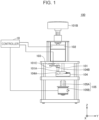
- Fig. 1 is a side view of a manipulation device 100 according to an embodiment.
- Fig. 2 is an external perspective view of the manipulation device 100 in the embodiment.
- the manipulation device 100 indicated in Fig. 1 and Fig. 2 is used in various electronic units (game controllers and the like, for example). With the manipulation device 100, a movement manipulation by pressing or the like by the user is possible.
- the manipulation device 100 has a manipulation shaft 101 (an example of a "manipulation unit") extending in the up-down direction (Z-axis direction).
- a manipulation knob 101B is attached to the manipulation shaft 101. In the example indicated in Fig. 1 and Fig. 2 , the manipulation knob 101B is attached to the upper end of the manipulation shaft 101.
- the manipulation shaft 101 can be moved downward by a pressing manipulation (an example of the "movement manipulation") in the downward direction for the manipulation knob 101B.
- a pressing manipulation an example of the "movement manipulation”
- An amount by which the manipulation shaft 101 moves downward is detected by a sensor 103 and is output from the sensor 103 to a controller 10.
- the manipulation device 100 has the manipulation shaft 101, a force sense generator 102, the sensor 103, an adjustment unit 104, an electrically powered unit 105, and the controller 10.
- the manipulation shaft 101 is a rod-like member extending in the up-down direction (Z-axis direction).
- the manipulation shaft 101 is provided so as to pass through the interior of the force sense generator 102.
- the manipulation shaft 101 can linearly move in the interior of the force sense generator 102 in the up-down direction (Z-axis direction).
- a tip 101A in a hemispherical shape is formed at the lower end (the end on the negative side of the Z axis) of the manipulation shaft 101.
- the tip 101A protrudes downward from the lower surface of the force sense generator 102.
- the upper end (the end on the positive side of the Z axis) of the manipulation shaft 101 protrudes upward from the upper surface of the force sense generator 102.
- the manipulation knob 101B is attached to the upper end (the end on the positive side of the Z axis) of the manipulation shaft 101.
- the force sense generator 102 is an example of a "load applying unit".
- the force sense generator 102 supports the manipulation shaft 101, which passes through the interior of the force sense generator 102, so that the manipulation shaft 101 is linearly movable in the up-down direction (Z-axis direction), and applies a force to the manipulation shaft 101. Due to this, the force sense generator 102 applies a load to the pressing manipulation for the manipulation knob 101B.
- the force sense generator 102 can operate under control of the controller 10.
- a voice coil motor is used as the force sense generator 102.
- another device such as, for example, a linear motor or a device that uses a magneto-rheological fluid
- the sensor 103 outputs a detection value according to the position of the manipulation shaft 101.
- the sensor 103 acquires the detection value according to the position of the manipulation shaft 101 and outputs the acquired detection value to the controller 10.
- the sensor 103 outputs a detection value according to the position of the manipulation shaft 101 at least in its axial direction.
- the sensor 103 is provided on the force sense generator 102 and outputs a detection value according to the distance to a reflecting plate 101C attached to the manipulation shaft 101.
- the sensor 103 may be, for example, a photo sensor.
- the adjustment unit 104 is a member that can adjust the movement limit position of the manipulation shaft 101.
- the adjustment unit 104 has a discoidal shape when viewed in, for example, the X-axis direction.
- the upper surface of the adjustment unit 104 is a contact surface 104A that the tip 101A of the manipulation shaft 101 will come into contact with.
- the contact surface 104A is formed spirally in a stepped shape so that its height position becomes higher with respect to the lowest height position as the height position proceeds counterclockwise in the circumferential direction.
- the electrically powered unit 105 is a device that can move the adjustment unit 104 to cause it to change the movement limit position of the manipulation shaft 101. Specifically, the electrically powered unit 105 rotates and moves the adjustment unit 104 to cause it to change the movement limit position of the manipulation shaft 101.
- the electrically powered unit 105 has a rotational axis 105A in a rod shape, which extends in the up-down direction (Z-axis direction), and a rotation driving body 105B, which can rotate the rotational axis 105A.
- the rotation driving body 105B can operate under control of the controller 10.
- a stepping motor for example, can be used as the rotation driving body 105B.
- the rotational axis 105A is provided concentrically with the rotational shaft 104B of the adjustment unit 104 and below the rotational shaft 104B.
- the rotational axis 105A is linked to the rotational shaft 104B. Due to this, the electrically powered unit 105 can rotate the adjustment unit 104 by driving of the rotation driving body 105B to rotate the rotational axis 105A.
- the manipulation shaft 101 moves downward. At this time, the amount of movement of the manipulation shaft 101 is detected by the sensor 103. Also, at this time, the manipulation device 100 can apply a driving force to the manipulation shaft 101 in the up-down direction (Z-axis direction) with the force sense generator 102. With the manipulation device 100, since the tip 101A of the manipulation shaft 101 is brought into contact with the contact surface 104A of the adjustment unit 104, the amount of downward movement of the manipulation shaft 101 is restricted.
- the adjustment unit 104 is caused to rotate and move under control of the controller 10, so the movement limit position of the manipulation shaft 101 can be adjusted to each of a plurality of movement limit positions.
- Fig. 3 is a graph indicating an example of load characteristics used by the manipulation device 100 in the embodiment in tactile presentation control.
- the graph indicated in Fig. 3 represents load characteristics used by the controller 10 that the manipulation device 100 has to control a load during a pressing manipulation by the manipulation knob 101B.
- the vertical axis represents load during a pressing manipulation and the horizontal axis indicates the amount of pressing in the pressing manipulation (that is, the amount of downward movement of the manipulation shaft 101).
- P1 indicates a "first pressing position" (pressing amount 448)
- P2 indicates a "second pressing position” (pressing amount 880)
- P3 indicates a "third pressing position” (pressing amount 1024).
- a load during the pressing manipulation is adjusted so that as the amount of pressing gradually increases, the load is gradually increased as indicated in Fig. 3 .
- the pressing position of the manipulation knob 101B has reached the first pressing position P1
- the force applied to the manipulation shaft 101 by the force sense generator 102 is controlled under control of the controller 10
- the load during the pressing manipulation is steeply reduced from the first maximum value (150) to the first minimum value (-100) as indicated in Fig. 3 .
- the manipulation knob 101B is urged to the same direction as the manipulation direction (that is, downward direction). Due to this, the manipulation device 100 can present a click feeling to the manipulator.
- the load during the pressing manipulation is adjusted so that as the amount of pressing gradually increases, the load is gradually increased as indicated in Fig. 3 .
- the pressing position of the manipulation knob 101B has reached the second pressing position P2
- the force applied to the manipulation shaft 101 by the force sense generator 102 is controlled under control of the controller 10
- the load during the pressing manipulation is steeply reduced from the second maximum value (255) to the second minimum value (-255) as indicated in Fig. 3 . Due to this, the manipulation device 100 can present a click feeling to the manipulator.
- the load during the pressing manipulation is adjusted so that as the amount of pressing gradually increases, the load is gradually increased as indicated in Fig. 3 .
- Fig. 4 is a drawing indicating an example of the functional structure of the controller 10 that the manipulation device 100 in the embodiment has.
- the controller 10 has a measurement unit 11, an acquisition unit 12, a conversion unit 13, a conversion information storage unit 14, a load characteristics storage unit 15, a load control unit 16, a creation unit 17, and a detection value acquisition control unit 18.
- the measurement unit 11 repeatedly executes measurement of time taken until a sensor read moment occurs.
- the sensor read moment repeatedly occurs at predetermined time intervals.
- the acquisition unit 12 acquires a detection value output from the sensor 103 each time a sensor read moment occurs.
- the conversion unit 13 converts a detection value acquired by the acquisition unit 12 to a stroke position of the manipulation shaft 101 (an example of a "manipulation unit position"), according to conversion information stored in the conversion information storage unit 14.
- the load characteristics storage unit 15 stores load characteristics (see Fig. 3 ) used to control the load of the pressing manipulation by the manipulation knob 101B.
- the load control unit 16 determines a load corresponding to the stroke position, obtained by the conversion unit 13, of the manipulation shaft 101, as a load to be applied to the manipulation shaft 101 (that is, the pressing manipulation for the manipulation knob 101B), according to the load characteristics stored in the load characteristics storage unit 15. Then, the load control unit 16 controls the force sense generator 102 to have it apply the determined load to the manipulation shaft 101 (that is, the pressing manipulation for the manipulation knob 101B).
- the creation unit 17 For each of a plurality of movement limit positions to be adjusted by the adjustment unit 104, the creation unit 17 acquires, from the sensor 103, a detection value at a time when the manipulation shaft 101 has reached the relevant movement limit position, after which the creation unit 17 creates conversion information to be used by the conversion unit 13, according to a plurality of acquired detection values and to positional information indicating the actual position of each of the plurality of movement limit positions.
- the conversion information created by the creation unit 17 is stored by the conversion information storage unit 14.
- the creation unit 17 creates an approximate expression used to calculate a stroke position of the manipulation shaft 101 from a detection value of the sensor 103, as an example of conversion information.
- the detection value acquisition control unit 18 sequentially adjusts the movement limit position of the manipulation shaft 101 to each of the plurality of movement limit positions by rotating the adjustment unit 104. Each time the movement limit position of the manipulation shaft 101 is adjusted, the detection value acquisition control unit 18 causes the manipulation shaft 101 to reach the relevant movement limit position and causes the creation unit 17 to acquire the detection value, of the sensor 103, corresponding to the relevant movement limit position.
- the controller 10 is structured by having, for example, a CPU (Central Processing Unit), a ROM (Read Only Memory), a RAM (Random Access Memory), and the like.
- Each functional unit, described above, of the controller 10 is implemented by, for example, the CPU's execution of programs stored in the ROM in the controller 10.
- Fig. 5 is a flowchart indicating an example of a procedure for processing by the controller 10 that the manipulation device 100 in the embodiment has.
- the detection value acquisition control unit 18 adjusts the movement limit position of the manipulation shaft 101 to any of a predetermined plurality of movement limit positions (that is, any of a plurality of steps that the contact surface 104A has) by controlling the electrically powered unit 105 to have it rotate the adjustment unit 104 (step S501).
- the detection value acquisition control unit 18 causes the manipulation shaft 101 to reach the movement limit position by controlling the force sense generator 102 to have it apply a force to the manipulation shaft 101 to move the manipulation shaft 101 downward (step S502).
- the force sense generator 102 functions as a movement control unit that can control the movement of the manipulation shaft 101.
- the detection value acquisition control unit 18 can decide that the manipulation shaft 101 has reached the movement limit position.
- the detection value acquisition control unit 18 may decide, by another method, that the manipulation shaft 101 has reached the movement limit position.
- the creation unit 17 acquires the detection value corresponding to the movement limit position from the sensor 103 (step S503).
- the detection value acquisition control unit 18 decides whether detection values have been acquired for all of the predetermined plurality of movement limit positions (step S504).
- step S504 If it is decided in step S504 that detection values have not been acquired for all of the predetermined plurality of movement limit positions (No in step S504), the controller 10 returns processing to step S501.
- step S504 determines whether detection values have been acquired for all of the predetermined plurality of movement limit positions (Yes in step S504). If it is decided in step S504 that detection values have been acquired for all of the predetermined plurality of movement limit positions (Yes in step S504), the creation unit 17 creates conversion information to be used by the conversion unit 13, according to a plurality of detection values acquired in step S503 and to positional information indicating the actual position of each of the predetermined plurality of movement limit positions (step S505).
- the creation unit 17 causes the conversion information storage unit 14 to store the conversion information created in step S505 (step S506). After that, the controller 10 terminates the series of processing indicated in Fig. 5 .
- Fig. 6 is a drawing indicating the structure of the adjustment unit 104 that the manipulation device 100 in the embodiment has.
- the adjustment unit 104 has the contact surface 104A formed spirally in a stepped shape. Due to this, along with the rotation of the adjustment unit 104, the adjustment unit 104 can change the contact position, at which the tip 101A of the manipulation shaft 101 makes contact, on the contact surface 104A in steps. Thus, the movement limit position of the manipulation shaft 101 can be changed in steps.
- the contact surface 104A has a ten-step spiral shape. Therefore, by rotating the adjustment unit 104 in increments of 36°, the manipulation device 100 in the embodiment can sequentially change the step of the contact surface 104A that the tip 101A of the manipulation shaft 101 will come into contact with.
- the contact surface 104A may be in a smooth spiral shape without being limited to a spirally stepped shape.
- the manipulation device 100 in the embodiment can steplessly change the height position of the contact surface 104A that the tip 101A will come into contact with.
- the contact surface 104A may be formed spirally in nine steps or less or may be formed spirally in 11 steps or more.
- the contact surface 104A is not limited to the above shapes. It suffices that the adjustment unit 104 has a contact surface having a plurality of contact positions along the axial direction of the manipulation shaft 101 and that the movement limit position of the manipulation shaft 101 used as a manipulation unit can be adjusted when a periphery in the axial direction is rotated to change the contact position at which the tip 101A of the manipulation shaft 101 will make contact.
- Fig. 7 is a drawing used to explain a method in which the sensor 103 that the manipulation device 100 in the embodiment has detects the position of the manipulation shaft 101.
- the adjustment unit 104 is provided immediately below the manipulation shaft 101, as indicated in Fig. 7 . Therefore, by moving the manipulation shaft 101 downward to bring the tip 101A of the manipulation shaft 101 into contact with the contact surface 104A of the adjustment unit 104, the manipulation device 100 in the embodiment enables the manipulation shaft 101 to reach the movement limit position, as indicated in Fig. 7(b) .
- the reflecting plate 101C is provided immediately below the sensor 103, as indicated in Fig. 7 . Since the reflecting plate 101C is fixed to the manipulation shaft 101, the reflecting plate 101C moves in the up-down direction (the Z-axis direction) together with the manipulation shaft 101. Therefore, when the manipulation shaft 101 has already reached the movement limit position as indicated in Fig. 7(b) , the sensor 103 can output a detection value corresponding to the movement limit position by detecting the distance to the reflecting plate 101C.
- the contact surface 104A of the adjustment unit 104 has a spirally stepped shape. Therefore, the manipulation device 100 in the embodiment can change the step, on the contact surface 104A, that the tip 101A of the manipulation shaft 101 will come into contact with by rotating the adjustment unit 104. Thus, the manipulation device 100 can adjust the movement limit position of the manipulation shaft 101.
- Fig. 8 is a drawing indicating an example of positional information and the detection value, which are used in the manipulation device 100 in the embodiment, for each movement limit position.
- positional information (in this embodiment, represented as the amount of stroke of the manipulation shaft 101) is set in advance for each of a plurality of movement limit positions, the positional information indicating the actual position of the movement limit position, as indicated in Fig. 8 .
- the manipulation device 100 in the embodiment acquires a detection value of the sensor 103 for each of the plurality of movement limit positions, the detection value corresponding to the position of the manipulation shaft 101 at the time when the manipulation shaft 101 has reached the relevant movement limit position, as indicated in Fig. 8 .
- positional information "0" indicates the amount of stroke of the manipulation shaft 101 at the time when no pressing manipulation has been performed, that is, the initial position of the manipulation shaft 101.
- a detection value of the sensor 103 has been acquired for this initial position of the manipulation shaft 101 as well.
- Fig. 9 is a drawing indicating an example of conversion information creation by the controller 10 that the manipulation device 100 in the embodiment has.
- the graph indicated in Fig. 9 represents an approximate expression created by the creation unit 17 in the controller 10.
- the vertical axis indicates the stroke position of the manipulation shaft 101, and the horizontal axis indicates the detection value of the sensor 103.
- the creation unit 17 in the controller 10 can create an approximate expression used to calculate a stroke position of the manipulation shaft 101 from a detection value of the sensor 103, according to positional information about each of a plurality of movement limit positions and to the detection value for each of the plurality of movement limit positions, the plurality of movement limit positions and the detection values for them being indicated in Fig. 8 .
- the approximate expression created in this way is stored in the conversion information storage unit 14 in the controller 10.
- the conversion unit 13 in the controller 10 can convert a detection value, acquired by the acquisition unit 12, of the sensor 103 to a stroke position of the manipulation shaft 101 by using the approximate expression stored in the conversion information storage unit 14.
- the approximate expression indicated in Fig. 9 is a highly precise approximate expression created according to a plurality of actually measured values (the detection values of a plurality of sensors 103) for which differences among individual manipulation devices 100 and the like have been additionally considered. Therefore, by calculating the stroke position of the manipulation shaft 101 by using the approximate expression indicated in Fig. 9 , the manipulation device 100 in the embodiment can highly precisely calculate the stroke position of the manipulation shaft 101 with the suppression of the effects of differences among individual manipulation devices 100, assembling error, time-varying changes, and the like.
- the manipulation device 100 may perform conversion information creation at a predetermined timing (for example, at shipping from the factory, at the time of first use, at intervals of a predetermined period, at intervals of a predetermined length of usage time, and the like) or at a timing specified by the user. Also, the manipulation device 100 can periodically create highly precise conversion information for which the effect of time-varying changes of the manipulation device 100 can be suppressed by periodically performing conversion information creation.
- an approximate expression is created as an example of conversion information.
- a conversion table for example, may be created that is used to convert a detection value of the sensor 103 to a stroke position of the manipulation shaft 101.
- the manipulation device 100 has: the manipulation shaft 101 on which a movement manipulation is possible, the sensor 103 that outputs a detection value according to the position of the manipulation shaft 101; the acquisition unit 12 that acquires the detection value output from the sensor 103; the conversion unit 13 that converts the detection value acquired by the acquisition unit 12 to the position of the manipulation shaft 101, according to conversion information; the adjustment unit 104 that can adjust the movement limit position of the manipulation shaft 101; and the creation unit 17 that acquires, from the sensor 103, a detection value at the time when the manipulation shaft 101 has reached the relevant movement limit position for each of a plurality of movement limit positions adjustable by the adjustment unit 104, and creates conversion information according to a plurality of acquired detection values and to positional information indicating the actual position of each of the plurality of movement limit positions.
- the manipulation device 100 in the embodiment by acquiring, from the sensor 103, a detection value at the time when the manipulation shaft 101 has reached a movement limit position, a detection value of the sensor 103 when the position of the manipulation shaft 101 is stable can be acquired, so more highly precise conversion information can be created.
- the creation unit 17 creates, as conversion information, an approximate expression used to calculate the position of the manipulation shaft 101 from a detection value of the sensor 103.
- the conversion unit 13 can highly precisely calculate the position of the manipulation shaft 101 from a detection value of the sensor 103 by using the approximate expression created by the creation unit 17. Also, according to the manipulation device 100 in the embodiment, by using the approximate expression, the position of the manipulation shaft 101 can be highly precisely calculated for an intermediate position as well, at which measurement for a detection value has not been performed when conversion information is created.
- the manipulation device 100 in the embodiment has the detection value acquisition control unit 18 that sequentially adjusts the adjustment unit 104 to each of the plurality of movement limit positions when the creation unit 17 creates conversion information, after which, at each movement limit position adjustment, the detection value acquisition control unit 18 causes the manipulation shaft 101 to reach the relevant movement limit position, and causes the creation unit 17 to acquire the detection value, of the sensor 103, corresponding to the relevant movement limit position.
- a detection value at each of a plurality of movement limit positions can be automatically acquired under control of the detection value acquisition control unit 18, so extra work involved in the user can be reduced.
- the manipulation device 100 in the embodiment has the force sense generator 102 (load applying unit) that applies a load to a movement manipulation for the manipulation shaft 101.
- the detection value acquisition control unit 18 causes the manipulation shaft 101 to reach the relevant movement limit position by driving the force sense generator 102.
- the manipulation device 100 in the embodiment it is possible to cause the manipulation shaft 101 to automatically reach a movement limit position under control of the detection value acquisition control unit 18, so extra work involved in the user can be reduced.
- a detection value of the sensor 103 is acquired for each of a plurality of positions, which have been set in advance, of the manipulation shaft 101, and conversion information is created according to a plurality of acquired detection values.
- the position of the manipulation shaft 101 may be measured for each of a plurality of detection values, which have been set in advance, of the sensor 103, and conversion information may be created according to a plurality of measured positions, for example.
- the detection value acquisition control unit 18 has caused the manipulation shaft 101 (manipulation unit) to automatically reach a movement limit position by driving the force sense generator 102 (movement control unit).
- the manipulation shaft 101 manipulation unit
- the force sense generator 102 movement control unit
- a structure may be taken in which the user manually causes the manipulation shaft 101 to reach a movement limit position by performing a movement manipulation for the manipulation shaft 101.
Landscapes
- Engineering & Computer Science (AREA)
- Physics & Mathematics (AREA)
- General Physics & Mathematics (AREA)
- Automation & Control Theory (AREA)
- Mechanical Engineering (AREA)
- General Engineering & Computer Science (AREA)
- Theoretical Computer Science (AREA)
- Human Computer Interaction (AREA)
- Mechanical Control Devices (AREA)
- Position Input By Displaying (AREA)
Abstract
Description
- The present invention relates to a manipulation device and a method.
- In PTL 1 below, a technology is disclosed by which, in a manipulation device having a manipulation member on which a pressing manipulation is possible, it is possible to control a load during the pressing manipulation and to present a tactile sense to the manipulator by converting a rotational angle detected by a rotational angle detection sensor to an amount by which the manipulation member has been pressed and controlling a motor according to the amount of pressing.
- PTL 1:
Japanese Unexamined Patent Application Publication No. 2019-219948 - With the technology in PTL 1, however, a conversion expression is needed to convert the rotational angle detected by the rotational angle detection sensor to an amount by which the manipulation member has been pressed. However, there is the fear that when an appropriate conversion expression is manually set individually for each manipulation device, extra work and time are taken. Also, there is the fear that if a conversion expression common to a plurality of manipulation devices is used, conversion precision is lowered due to differences among individual manipulation devices, assembling error, time-varying changes, and the like.
- A manipulation device according to an embodiment has: a manipulation unit on which a movement manipulation is possible; sensor that outputs a detection value according to the position of the manipulation unit; a conversion unit that converts a detection value acquired by an acquisition unit to information about the position of the manipulation unit, according to conversion information; an adjustment unit that can adjust the movement limit position of the manipulation unit; and a creation unit that acquires, from the sensor, a detection value at the time when the manipulation unit has reached the relevant movement limit position for each of a plurality of movement limit positions adjustable by the adjustment unit, and creates the conversion information according to a plurality of acquired detection values and to positional information indicating the actual position of each of the plurality of movement limit positions.
- According to the manipulation device in the embodiment, it is possible to easily create highly precise conversion information used to convert a detection value of the sensor to the position of the manipulation unit.
-
- [
Fig. 1] Fig. 1 is a side view of a manipulation device according to an embodiment. - [
Fig. 2] Fig. 2 is an external perspective view of the manipulation device in the embodiment. - [
Fig. 3] Fig. 3 is a graph indicating an example of load characteristics used by the manipulation device in the embodiment in tactile presentation control. - [
Fig. 4] Fig. 4 is a drawing indicating an example of the functional structure of a controller that the manipulation device in the embodiment has. - [
Fig. 5] Fig. 5 is a flowchart indicating an example of a procedure for processing by the controller that the manipulation device in the embodiment has. - [
Fig. 6] Fig. 6 is a drawing indicating the structure of adjustment that the manipulation device in the embodiment has. - [
Fig. 7] Fig. 7 is a drawing used to explain a method in which a sensor that the manipulation device in the embodiment has detects the position of a manipulation shaft. - [
Fig. 8] Fig. 8 is a drawing indicating an example of positional information and a detection value, which are used in the manipulation device in the embodiment, for each movement limit position. - [
Fig. 9] Fig. 9 is a drawing indicating an example of conversion information creation by the controller that the manipulation device in the embodiment has. - An embodiment will be described below with reference to the drawings. Incidentally, in the description below, the Z-axis direction will be taken as the up-down direction, the X-axis direction will be taken as the front-back direction, and the Y-axis direction will be taken as the left-right direction, for convenience of explanation. However, the positive Z-axis direction will be taken as the upward direction, the positive X-axis direction will be taken as the forward direction, and the positive Y-axis direction will be taken as the right direction.
-
Fig. 1 is a side view of amanipulation device 100 according to an embodiment.Fig. 2 is an external perspective view of themanipulation device 100 in the embodiment. Themanipulation device 100 indicated inFig. 1 andFig. 2 is used in various electronic units (game controllers and the like, for example). With themanipulation device 100, a movement manipulation by pressing or the like by the user is possible. As indicated inFig. 1 andFig. 2 , themanipulation device 100 has a manipulation shaft 101 (an example of a "manipulation unit") extending in the up-down direction (Z-axis direction). Amanipulation knob 101B is attached to themanipulation shaft 101. In the example indicated inFig. 1 andFig. 2 , themanipulation knob 101B is attached to the upper end of themanipulation shaft 101. With themanipulation device 100, themanipulation shaft 101 can be moved downward by a pressing manipulation (an example of the "movement manipulation") in the downward direction for themanipulation knob 101B. An amount by which themanipulation shaft 101 moves downward is detected by asensor 103 and is output from thesensor 103 to acontroller 10. - As indicated in
Fig. 1 andFig. 2 , themanipulation device 100 has themanipulation shaft 101, aforce sense generator 102, thesensor 103, anadjustment unit 104, an electrically poweredunit 105, and thecontroller 10. - The
manipulation shaft 101 is a rod-like member extending in the up-down direction (Z-axis direction). Themanipulation shaft 101 is provided so as to pass through the interior of theforce sense generator 102. Themanipulation shaft 101 can linearly move in the interior of theforce sense generator 102 in the up-down direction (Z-axis direction). Atip 101A in a hemispherical shape is formed at the lower end (the end on the negative side of the Z axis) of themanipulation shaft 101. Thetip 101A protrudes downward from the lower surface of theforce sense generator 102. The upper end (the end on the positive side of the Z axis) of themanipulation shaft 101 protrudes upward from the upper surface of theforce sense generator 102. Themanipulation knob 101B is attached to the upper end (the end on the positive side of the Z axis) of themanipulation shaft 101. - The
force sense generator 102 is an example of a "load applying unit". Theforce sense generator 102 supports themanipulation shaft 101, which passes through the interior of theforce sense generator 102, so that themanipulation shaft 101 is linearly movable in the up-down direction (Z-axis direction), and applies a force to themanipulation shaft 101. Due to this, theforce sense generator 102 applies a load to the pressing manipulation for themanipulation knob 101B. Theforce sense generator 102 can operate under control of thecontroller 10. In this embodiment, a voice coil motor is used as theforce sense generator 102. However, without being limited by this, another device (such as, for example, a linear motor or a device that uses a magneto-rheological fluid) may be used as theforce sense generator 102. - The
sensor 103 outputs a detection value according to the position of themanipulation shaft 101. Thesensor 103 acquires the detection value according to the position of themanipulation shaft 101 and outputs the acquired detection value to thecontroller 10. Thesensor 103 outputs a detection value according to the position of themanipulation shaft 101 at least in its axial direction. In this embodiment, thesensor 103 is provided on theforce sense generator 102 and outputs a detection value according to the distance to a reflectingplate 101C attached to themanipulation shaft 101. Thesensor 103 may be, for example, a photo sensor. - The
adjustment unit 104 is a member that can adjust the movement limit position of themanipulation shaft 101. Theadjustment unit 104 has a discoidal shape when viewed in, for example, the X-axis direction. The upper surface of theadjustment unit 104 is acontact surface 104A that thetip 101A of themanipulation shaft 101 will come into contact with. As indicated inFig. 1 andFig. 2 , thecontact surface 104A is formed spirally in a stepped shape so that its height position becomes higher with respect to the lowest height position as the height position proceeds counterclockwise in the circumferential direction. Also, arotational shaft 104B in a rod shape, which extends in the up-down direction (Z-axis direction), is provided at the center of theadjustment unit 104 in the X-axis direction and Y-axis direction. Due to this, theadjustment unit 104 is rotatable with therotational shaft 104B taken as the center of rotation. Incidentally, therotational shaft 104B is provided with a greater offset in the right direction (the positive direction of the Y axis) than does themanipulation shaft 101. Due to this, with themanipulation device 100 in the embodiment, thetip 101A of themanipulation shaft 101 can be brought into contact with thecontact surface 104A. - The electrically
powered unit 105 is a device that can move theadjustment unit 104 to cause it to change the movement limit position of themanipulation shaft 101. Specifically, the electricallypowered unit 105 rotates and moves theadjustment unit 104 to cause it to change the movement limit position of themanipulation shaft 101. The electricallypowered unit 105 has arotational axis 105A in a rod shape, which extends in the up-down direction (Z-axis direction), and arotation driving body 105B, which can rotate therotational axis 105A. Therotation driving body 105B can operate under control of thecontroller 10. A stepping motor, for example, can be used as therotation driving body 105B. Therotational axis 105A is provided concentrically with therotational shaft 104B of theadjustment unit 104 and below therotational shaft 104B. Therotational axis 105A is linked to therotational shaft 104B. Due to this, the electricallypowered unit 105 can rotate theadjustment unit 104 by driving of therotation driving body 105B to rotate therotational axis 105A. - With the
manipulation device 100 in the embodiment, when a pressing manipulation for themanipulation knob 101B is performed, themanipulation shaft 101 moves downward. At this time, the amount of movement of themanipulation shaft 101 is detected by thesensor 103. Also, at this time, themanipulation device 100 can apply a driving force to themanipulation shaft 101 in the up-down direction (Z-axis direction) with theforce sense generator 102. With themanipulation device 100, since thetip 101A of themanipulation shaft 101 is brought into contact with thecontact surface 104A of theadjustment unit 104, the amount of downward movement of themanipulation shaft 101 is restricted. - With the
manipulation device 100 in the embodiment, theadjustment unit 104 is caused to rotate and move under control of thecontroller 10, so the movement limit position of themanipulation shaft 101 can be adjusted to each of a plurality of movement limit positions. - That is, with the
manipulation device 100 in the embodiment, the lower the height position of thecontact surface 104A positioned immediately below thetip 101A is, the more greatly the maximum amount of pressing of themanipulation shaft 101 can be increased. The higher the height position of thecontact surface 104A positioned immediately below thetip 101A is, the more greatly the maximum amount of pressing of themanipulation shaft 101 can be reduced. -
Fig. 3 is a graph indicating an example of load characteristics used by themanipulation device 100 in the embodiment in tactile presentation control. The graph indicated inFig. 3 represents load characteristics used by thecontroller 10 that themanipulation device 100 has to control a load during a pressing manipulation by themanipulation knob 101B. In the graph indicated inFig. 3 , the vertical axis represents load during a pressing manipulation and the horizontal axis indicates the amount of pressing in the pressing manipulation (that is, the amount of downward movement of the manipulation shaft 101). Also, in the graph indicated inFig. 3 , P1 indicates a "first pressing position" (pressing amount 448), P2 indicates a "second pressing position" (pressing amount 880), and P3 indicates a "third pressing position" (pressing amount 1024). - During a time until the pressing position of the
manipulation knob 101B reaches the first pressing position P1, since a force applied to themanipulation shaft 101 by theforce sense generator 102 is controlled under control of thecontroller 10, a load during the pressing manipulation is adjusted so that as the amount of pressing gradually increases, the load is gradually increased as indicated inFig. 3 . - When the pressing position of the
manipulation knob 101B has reached the first pressing position P1, since the force applied to themanipulation shaft 101 by theforce sense generator 102 is controlled under control of thecontroller 10, the load during the pressing manipulation is steeply reduced from the first maximum value (150) to the first minimum value (-100) as indicated inFig. 3 . At this time, since the load during the pressing manipulation is steeply reduced, themanipulation knob 101B is urged to the same direction as the manipulation direction (that is, downward direction). Due to this, themanipulation device 100 can present a click feeling to the manipulator. - Next, during a time until the pressing position of the
manipulation knob 101B reaches the second pressing position P2 after the first pressing position P1, since the force applied to themanipulation shaft 101 by theforce sense generator 102 is controlled under control of thecontroller 10, the load during the pressing manipulation is adjusted so that as the amount of pressing gradually increases, the load is gradually increased as indicated inFig. 3 . - When the pressing position of the
manipulation knob 101B has reached the second pressing position P2, since the force applied to themanipulation shaft 101 by theforce sense generator 102 is controlled under control of thecontroller 10, the load during the pressing manipulation is steeply reduced from the second maximum value (255) to the second minimum value (-255) as indicated inFig. 3 . Due to this, themanipulation device 100 can present a click feeling to the manipulator. - Next, during a time until the pressing position of the
manipulation knob 101B reaches the third pressing position P3 after the second pressing position P2, since the force applied to themanipulation shaft 101 by theforce sense generator 102 is controlled under control of thecontroller 10, the load during the pressing manipulation is adjusted so that as the amount of pressing gradually increases, the load is gradually increased as indicated inFig. 3 . - When the pressing position of the
manipulation knob 101B has reached the third pressing position P3, the load during the pressing manipulation is controlled to the second maximum value (255) as indicated inFig. 3 . -
Fig. 4 is a drawing indicating an example of the functional structure of thecontroller 10 that themanipulation device 100 in the embodiment has. As indicated inFig. 4 , thecontroller 10 has ameasurement unit 11, anacquisition unit 12, aconversion unit 13, a conversioninformation storage unit 14, a loadcharacteristics storage unit 15, aload control unit 16, acreation unit 17, and a detection valueacquisition control unit 18. - The
measurement unit 11 repeatedly executes measurement of time taken until a sensor read moment occurs. In thecontroller 10, the sensor read moment repeatedly occurs at predetermined time intervals. - The
acquisition unit 12 acquires a detection value output from thesensor 103 each time a sensor read moment occurs. - The
conversion unit 13 converts a detection value acquired by theacquisition unit 12 to a stroke position of the manipulation shaft 101 (an example of a "manipulation unit position"), according to conversion information stored in the conversioninformation storage unit 14. - The load
characteristics storage unit 15 stores load characteristics (seeFig. 3 ) used to control the load of the pressing manipulation by themanipulation knob 101B. - The
load control unit 16 determines a load corresponding to the stroke position, obtained by theconversion unit 13, of themanipulation shaft 101, as a load to be applied to the manipulation shaft 101 (that is, the pressing manipulation for themanipulation knob 101B), according to the load characteristics stored in the loadcharacteristics storage unit 15. Then, theload control unit 16 controls theforce sense generator 102 to have it apply the determined load to the manipulation shaft 101 (that is, the pressing manipulation for themanipulation knob 101B). - For each of a plurality of movement limit positions to be adjusted by the
adjustment unit 104, thecreation unit 17 acquires, from thesensor 103, a detection value at a time when themanipulation shaft 101 has reached the relevant movement limit position, after which thecreation unit 17 creates conversion information to be used by theconversion unit 13, according to a plurality of acquired detection values and to positional information indicating the actual position of each of the plurality of movement limit positions. The conversion information created by thecreation unit 17 is stored by the conversioninformation storage unit 14. - In this embodiment, the
creation unit 17 creates an approximate expression used to calculate a stroke position of themanipulation shaft 101 from a detection value of thesensor 103, as an example of conversion information. - When the
creation unit 17 creates conversion information, the detection valueacquisition control unit 18 sequentially adjusts the movement limit position of themanipulation shaft 101 to each of the plurality of movement limit positions by rotating theadjustment unit 104. Each time the movement limit position of themanipulation shaft 101 is adjusted, the detection valueacquisition control unit 18 causes themanipulation shaft 101 to reach the relevant movement limit position and causes thecreation unit 17 to acquire the detection value, of thesensor 103, corresponding to the relevant movement limit position. - Incidentally, the
controller 10 is structured by having, for example, a CPU (Central Processing Unit), a ROM (Read Only Memory), a RAM (Random Access Memory), and the like. Each functional unit, described above, of thecontroller 10 is implemented by, for example, the CPU's execution of programs stored in the ROM in thecontroller 10. -
Fig. 5 is a flowchart indicating an example of a procedure for processing by thecontroller 10 that themanipulation device 100 in the embodiment has. - First, the detection value
acquisition control unit 18 adjusts the movement limit position of themanipulation shaft 101 to any of a predetermined plurality of movement limit positions (that is, any of a plurality of steps that thecontact surface 104A has) by controlling the electricallypowered unit 105 to have it rotate the adjustment unit 104 (step S501). - Next, the detection value
acquisition control unit 18 causes themanipulation shaft 101 to reach the movement limit position by controlling theforce sense generator 102 to have it apply a force to themanipulation shaft 101 to move themanipulation shaft 101 downward (step S502). At this time, theforce sense generator 102 functions as a movement control unit that can control the movement of themanipulation shaft 101. - In this case, when, for example, the output value of the
sensor 103 does not change any longer, the detection valueacquisition control unit 18 can decide that themanipulation shaft 101 has reached the movement limit position. However, without being limited by this, the detection valueacquisition control unit 18 may decide, by another method, that themanipulation shaft 101 has reached the movement limit position. - Next, the
creation unit 17 acquires the detection value corresponding to the movement limit position from the sensor 103 (step S503). - Next, the detection value
acquisition control unit 18 decides whether detection values have been acquired for all of the predetermined plurality of movement limit positions (step S504). - If it is decided in step S504 that detection values have not been acquired for all of the predetermined plurality of movement limit positions (No in step S504), the
controller 10 returns processing to step S501. - Conversely, if it is decided in step S504 that detection values have been acquired for all of the predetermined plurality of movement limit positions (Yes in step S504), the
creation unit 17 creates conversion information to be used by theconversion unit 13, according to a plurality of detection values acquired in step S503 and to positional information indicating the actual position of each of the predetermined plurality of movement limit positions (step S505). - Then, the
creation unit 17 causes the conversioninformation storage unit 14 to store the conversion information created in step S505 (step S506). After that, thecontroller 10 terminates the series of processing indicated inFig. 5 . -
Fig. 6 is a drawing indicating the structure of theadjustment unit 104 that themanipulation device 100 in the embodiment has. As indicated inFig. 6 , theadjustment unit 104 has thecontact surface 104A formed spirally in a stepped shape. Due to this, along with the rotation of theadjustment unit 104, theadjustment unit 104 can change the contact position, at which thetip 101A of themanipulation shaft 101 makes contact, on thecontact surface 104A in steps. Thus, the movement limit position of themanipulation shaft 101 can be changed in steps. Particularly, in the example indicated inFig. 6 , thecontact surface 104A has a ten-step spiral shape. Therefore, by rotating theadjustment unit 104 in increments of 36°, themanipulation device 100 in the embodiment can sequentially change the step of thecontact surface 104A that thetip 101A of themanipulation shaft 101 will come into contact with. - Incidentally, the
contact surface 104A may be in a smooth spiral shape without being limited to a spirally stepped shape. In this case, by rotating and moving theadjustment unit 104, themanipulation device 100 in the embodiment can steplessly change the height position of thecontact surface 104A that thetip 101A will come into contact with. Also, thecontact surface 104A may be formed spirally in nine steps or less or may be formed spirally in 11 steps or more. - Furthermore, the
contact surface 104A is not limited to the above shapes. It suffices that theadjustment unit 104 has a contact surface having a plurality of contact positions along the axial direction of themanipulation shaft 101 and that the movement limit position of themanipulation shaft 101 used as a manipulation unit can be adjusted when a periphery in the axial direction is rotated to change the contact position at which thetip 101A of themanipulation shaft 101 will make contact. -
Fig. 7 is a drawing used to explain a method in which thesensor 103 that themanipulation device 100 in the embodiment has detects the position of themanipulation shaft 101. - In the
manipulation device 100 in the embodiment, theadjustment unit 104 is provided immediately below themanipulation shaft 101, as indicated inFig. 7 . Therefore, by moving themanipulation shaft 101 downward to bring thetip 101A of themanipulation shaft 101 into contact with thecontact surface 104A of theadjustment unit 104, themanipulation device 100 in the embodiment enables themanipulation shaft 101 to reach the movement limit position, as indicated inFig. 7(b) . - Also, in the
manipulation device 100 in the embodiment, the reflectingplate 101C is provided immediately below thesensor 103, as indicated inFig. 7 . Since the reflectingplate 101C is fixed to themanipulation shaft 101, the reflectingplate 101C moves in the up-down direction (the Z-axis direction) together with themanipulation shaft 101. Therefore, when themanipulation shaft 101 has already reached the movement limit position as indicated inFig. 7(b) , thesensor 103 can output a detection value corresponding to the movement limit position by detecting the distance to the reflectingplate 101C. - The
contact surface 104A of theadjustment unit 104 has a spirally stepped shape. Therefore, themanipulation device 100 in the embodiment can change the step, on thecontact surface 104A, that thetip 101A of themanipulation shaft 101 will come into contact with by rotating theadjustment unit 104. Thus, themanipulation device 100 can adjust the movement limit position of themanipulation shaft 101. -
Fig. 8 is a drawing indicating an example of positional information and the detection value, which are used in themanipulation device 100 in the embodiment, for each movement limit position. - In the
manipulation device 100 in the embodiment, positional information (in this embodiment, represented as the amount of stroke of the manipulation shaft 101) is set in advance for each of a plurality of movement limit positions, the positional information indicating the actual position of the movement limit position, as indicated inFig. 8 . - Then, the
manipulation device 100 in the embodiment acquires a detection value of thesensor 103 for each of the plurality of movement limit positions, the detection value corresponding to the position of themanipulation shaft 101 at the time when themanipulation shaft 101 has reached the relevant movement limit position, as indicated inFig. 8 . - In the example indicated in
Fig. 8 , since thecontact surface 104A of theadjustment unit 104 has a ten-step spiral shape, positional information is set in advance for each of 10 movement limit positions, which are determined by thecontact surface 104A. In addition, detection values of thesensor 103 have been acquired. - Incidentally, in
Fig. 8 , positional information "0" indicates the amount of stroke of themanipulation shaft 101 at the time when no pressing manipulation has been performed, that is, the initial position of themanipulation shaft 101. In the example indicated inFig. 8 , a detection value of thesensor 103 has been acquired for this initial position of themanipulation shaft 101 as well. -
Fig. 9 is a drawing indicating an example of conversion information creation by thecontroller 10 that themanipulation device 100 in the embodiment has. The graph indicated inFig. 9 represents an approximate expression created by thecreation unit 17 in thecontroller 10. The vertical axis indicates the stroke position of themanipulation shaft 101, and the horizontal axis indicates the detection value of thesensor 103. - As indicated in
Fig. 9 , thecreation unit 17 in thecontroller 10 can create an approximate expression used to calculate a stroke position of themanipulation shaft 101 from a detection value of thesensor 103, according to positional information about each of a plurality of movement limit positions and to the detection value for each of the plurality of movement limit positions, the plurality of movement limit positions and the detection values for them being indicated inFig. 8 . - The approximate expression created in this way is stored in the conversion
information storage unit 14 in thecontroller 10. After that, theconversion unit 13 in thecontroller 10 can convert a detection value, acquired by theacquisition unit 12, of thesensor 103 to a stroke position of themanipulation shaft 101 by using the approximate expression stored in the conversioninformation storage unit 14. - The approximate expression indicated in
Fig. 9 is a highly precise approximate expression created according to a plurality of actually measured values (the detection values of a plurality of sensors 103) for which differences amongindividual manipulation devices 100 and the like have been additionally considered. Therefore, by calculating the stroke position of themanipulation shaft 101 by using the approximate expression indicated inFig. 9 , themanipulation device 100 in the embodiment can highly precisely calculate the stroke position of themanipulation shaft 101 with the suppression of the effects of differences amongindividual manipulation devices 100, assembling error, time-varying changes, and the like. - Incidentally, the
manipulation device 100 may perform conversion information creation at a predetermined timing (for example, at shipping from the factory, at the time of first use, at intervals of a predetermined period, at intervals of a predetermined length of usage time, and the like) or at a timing specified by the user. Also, themanipulation device 100 can periodically create highly precise conversion information for which the effect of time-varying changes of themanipulation device 100 can be suppressed by periodically performing conversion information creation. - Also, in this embodiment, an approximate expression is created as an example of conversion information. However, without being limited by this, this is not a limitation, a conversion table, for example, may be created that is used to convert a detection value of the
sensor 103 to a stroke position of themanipulation shaft 101. - As described above, the
manipulation device 100 according to the embodiment has: themanipulation shaft 101 on which a movement manipulation is possible, thesensor 103 that outputs a detection value according to the position of themanipulation shaft 101; theacquisition unit 12 that acquires the detection value output from thesensor 103; theconversion unit 13 that converts the detection value acquired by theacquisition unit 12 to the position of themanipulation shaft 101, according to conversion information; theadjustment unit 104 that can adjust the movement limit position of themanipulation shaft 101; and thecreation unit 17 that acquires, from thesensor 103, a detection value at the time when themanipulation shaft 101 has reached the relevant movement limit position for each of a plurality of movement limit positions adjustable by theadjustment unit 104, and creates conversion information according to a plurality of acquired detection values and to positional information indicating the actual position of each of the plurality of movement limit positions. - Due to this, according to the
manipulation device 100 in the embodiment, highly precise conversion information used to convert a detection value of thesensor 103 to the position of themanipulation shaft 101 can be easily created. - Particularly, according to the
manipulation device 100 in the embodiment, by acquiring, from thesensor 103, a detection value at the time when themanipulation shaft 101 has reached a movement limit position, a detection value of thesensor 103 when the position of themanipulation shaft 101 is stable can be acquired, so more highly precise conversion information can be created. - Also, in the
manipulation device 100 in the embodiment, thecreation unit 17 creates, as conversion information, an approximate expression used to calculate the position of themanipulation shaft 101 from a detection value of thesensor 103. - Due to this, according to the
manipulation device 100 in the embodiment, theconversion unit 13 can highly precisely calculate the position of themanipulation shaft 101 from a detection value of thesensor 103 by using the approximate expression created by thecreation unit 17. Also, according to themanipulation device 100 in the embodiment, by using the approximate expression, the position of themanipulation shaft 101 can be highly precisely calculated for an intermediate position as well, at which measurement for a detection value has not been performed when conversion information is created. - Also, the
manipulation device 100 in the embodiment has the detection valueacquisition control unit 18 that sequentially adjusts theadjustment unit 104 to each of the plurality of movement limit positions when thecreation unit 17 creates conversion information, after which, at each movement limit position adjustment, the detection valueacquisition control unit 18 causes themanipulation shaft 101 to reach the relevant movement limit position, and causes thecreation unit 17 to acquire the detection value, of thesensor 103, corresponding to the relevant movement limit position. - Due to this, according to the
manipulation device 100 in the embodiment, a detection value at each of a plurality of movement limit positions can be automatically acquired under control of the detection valueacquisition control unit 18, so extra work involved in the user can be reduced. - Also, the
manipulation device 100 in the embodiment has the force sense generator 102 (load applying unit) that applies a load to a movement manipulation for themanipulation shaft 101. The detection valueacquisition control unit 18 causes themanipulation shaft 101 to reach the relevant movement limit position by driving theforce sense generator 102. - Due to this, according to the
manipulation device 100 in the embodiment, it is possible to cause themanipulation shaft 101 to automatically reach a movement limit position under control of the detection valueacquisition control unit 18, so extra work involved in the user can be reduced. - So far, an embodiment of the present invention has been described in detail. However, the present invention is not limited to the embodiment. Various variations and modifications are possible without departing from the intended scope, described in the claims, of the present invention.
- In the embodiment, an example has been described in which the present invention is applied to a manipulation device on which a pressing manipulation is possible as an example of a "movement manipulation by the manipulation unit". However, without being limited by this, the present invention can also be applied to a manipulation device on which other manipulations (such as, for example, a rotation manipulation, a slide manipulation, and the like) are possible as "movement manipulations by the manipulation unit".
- Also, in this embodiment, a detection value of the
sensor 103 is acquired for each of a plurality of positions, which have been set in advance, of themanipulation shaft 101, and conversion information is created according to a plurality of acquired detection values. However, the position of themanipulation shaft 101 may be measured for each of a plurality of detection values, which have been set in advance, of thesensor 103, and conversion information may be created according to a plurality of measured positions, for example. - Also, in the structure in the embodiment, the detection value
acquisition control unit 18 has caused the manipulation shaft 101 (manipulation unit) to automatically reach a movement limit position by driving the force sense generator 102 (movement control unit). However, without being limited by this, a structure may be taken in which the user manually causes themanipulation shaft 101 to reach a movement limit position by performing a movement manipulation for themanipulation shaft 101. - This international application claims priority based on
Japanese Patent Application No. 2022-081739 filed on May 18, 2022 -
- 10 controller
- 11 measurement unit
- 12 acquisition unit
- 13 conversion unit
- 14 conversion information storage unit
- 15 load characteristics storage unit
- 16 load control unit
- 17 creation unit
- 18 detection value acquisition control unit
- 100 manipulation device
- 101 manipulation shaft (manipulation unit)
- 101A tip
- 101B manipulation knob
- 101C reflecting plate
- 102 force sense generator (load applying unit)
- 103 sensor
- 104 adjustment unit
- 104A contact surface
- 104B rotational shaft
- 105 electrically powered unit
- 105A rotational axis
- 105B rotation driving body
- P1 first pressing position
- P2 second pressing position
- P3 third pressing position
Claims (9)
- A manipulation device characterized by having:a manipulation unit on which a movement manipulation is possible;a sensor that outputs a detection value according to a position of the manipulation unit;a conversion unit that converts the detection value to information about a position of the manipulation unit, according to conversion information;an adjustment unit capable of adjusting a movement limit position of the manipulation unit; anda creation unit that acquires, from the sensor, the detection value at a time when the manipulation unit has reached a relevant movement limit position for each of a plurality of movement limit positions adjustable by the adjustment unit, and creates the conversion information according to a plurality of acquired detection values and to positional information indicating an actual position of each of the plurality of movement limit positions.
- The manipulation device according to claim 1, characterized in that the creation unit creates, as the conversion information, an approximate expression used to calculate the position of the manipulation unit from the detection value.
- The manipulation device according to claim 1, characterized by further having a detection value acquisition control unit that sequentially adjusts the adjustment unit to each of the plurality of movement limit positions when the creation unit creates the conversion information, after which, at each movement limit position adjustment, the detection value acquisition control unit causes the manipulation unit to reach the relevant movement limit position, and causes the creation unit to acquire the detection value corresponding to the relevant movement limit position.
- The manipulation device according to claim 3, characterized by further having a movement control unit that is capable of controlling movement of the manipulation unit, the manipulation device being characterized in that
the detection value acquisition control unit causes the manipulation unit to reach the relevant movement limit position by driving the movement control unit. - The manipulation device according to claim 4, characterized in that the movement control unit is a load applying unit that applies a load to a movement manipulation for the manipulation unit.
- The manipulation device according to claim 1, characterized in that:the manipulation unit has a manipulation shaft that moves in an axial direction due to the movement manipulation; andthe adjustment unit has a contact surface, and is capable of adjusting the movement limit position of the manipulation unit by changing a contact position at which a tip of the manipulation shaft will make contact, the contact position being on the contact surface.
- The manipulation device according to claim 6, characterized in that the adjustment unit has a contact surface having a plurality of contact positions along the axial direction as the contact surface, and is capable of adjusting the movement limit position of the manipulation unit when a periphery in the axial direction is rotated to change the contact position at which the tip of the manipulation shaft will make contact.
- The manipulation device according to claim 1 characterized in that the sensor outputs a detection value according to a distance to a position of the manipulation unit in the axial direction, as the detection value.
- A method in which a manipulation device is used that has a manipulation unit on which a movement manipulation is possible and an adjustment unit capable of adjusting a movement limit position of the manipulation unit, the method being characterized by comprising the steps of:outputting a detection value according to a position of the manipulation unit;converting the detection value to information about a position of the manipulation unit, according to conversion information; andacquiring the detection value at a time when the manipulation unit has reached a relevant movement limit position for each of a plurality of movement limit positions adjustable by the adjustment unit, and creating the conversion information according to a plurality of acquired detection values and to positional information indicating an actual position of each of the plurality of movement limit positions.
Applications Claiming Priority (2)
| Application Number | Priority Date | Filing Date | Title |
|---|---|---|---|
| JP2022081739 | 2022-05-18 | ||
| PCT/JP2023/008286 WO2023223633A1 (en) | 2022-05-18 | 2023-03-06 | Operation device and method |
Publications (2)
| Publication Number | Publication Date |
|---|---|
| EP4528419A1 true EP4528419A1 (en) | 2025-03-26 |
| EP4528419A4 EP4528419A4 (en) | 2026-04-29 |
Family
ID=88835270
Family Applications (1)
| Application Number | Title | Priority Date | Filing Date |
|---|---|---|---|
| EP23807249.0A Pending EP4528419A4 (en) | 2022-05-18 | 2023-03-06 | OPERATING DEVICE AND PROCEDURES |
Country Status (6)
| Country | Link |
|---|---|
| US (1) | US20250026099A1 (en) |
| EP (1) | EP4528419A4 (en) |
| JP (1) | JP7728452B2 (en) |
| KR (1) | KR20250006900A (en) |
| CN (1) | CN119213385A (en) |
| WO (1) | WO2023223633A1 (en) |
Family Cites Families (8)
| Publication number | Priority date | Publication date | Assignee | Title |
|---|---|---|---|---|
| JP2007212380A (en) | 2006-02-13 | 2007-08-23 | Toyota Motor Corp | Calibration jig and calibration processing system |
| JP2008027843A (en) * | 2006-07-25 | 2008-02-07 | Omron Corp | Switch device |
| JP5091488B2 (en) | 2007-01-16 | 2012-12-05 | 株式会社ソニー・コンピュータエンタテインメント | Controller and information processing system |
| WO2018020778A1 (en) * | 2016-07-26 | 2018-02-01 | 株式会社ソニー・インタラクティブエンタテインメント | Information processing system, operation device, and method for controlling operation device |
| JP6852195B2 (en) * | 2018-01-19 | 2021-03-31 | 株式会社ソニー・インタラクティブエンタテインメント | Operation input device |
| JP7018830B2 (en) | 2018-06-20 | 2022-02-14 | アルプスアルパイン株式会社 | Operation system, operation device, control device, control method, and program |
| US12173777B2 (en) * | 2020-10-23 | 2024-12-24 | Nsk Ltd. | Linear motion actuator |
| JP2022081739A (en) | 2020-11-20 | 2022-06-01 | 株式会社ユニバーサルエンターテインメント | Game machine |
-
2023
- 2023-03-06 EP EP23807249.0A patent/EP4528419A4/en active Pending
- 2023-03-06 CN CN202380040239.9A patent/CN119213385A/en active Pending
- 2023-03-06 KR KR1020247038162A patent/KR20250006900A/en active Pending
- 2023-03-06 WO PCT/JP2023/008286 patent/WO2023223633A1/en not_active Ceased
- 2023-03-06 JP JP2024521566A patent/JP7728452B2/en active Active
-
2024
- 2024-10-07 US US18/907,949 patent/US20250026099A1/en active Pending
Also Published As
| Publication number | Publication date |
|---|---|
| JP7728452B2 (en) | 2025-08-22 |
| KR20250006900A (en) | 2025-01-13 |
| WO2023223633A1 (en) | 2023-11-23 |
| US20250026099A1 (en) | 2025-01-23 |
| EP4528419A4 (en) | 2026-04-29 |
| JPWO2023223633A1 (en) | 2023-11-23 |
| CN119213385A (en) | 2024-12-27 |
Similar Documents
| Publication | Publication Date | Title |
|---|---|---|
| JP5410317B2 (en) | CMM | |
| JP6235009B2 (en) | Operating device and method for controlling a mobile device | |
| EP1452826B1 (en) | Contact measuring instrument | |
| JP6296236B2 (en) | Master device for master-slave device, control method therefor, and master-slave device | |
| JP2012026865A (en) | Shape measurement device | |
| US9764191B2 (en) | Training apparatus | |
| US10001358B2 (en) | Measuring probe and measuring probe system | |
| JP2009127379A (en) | Electronic control faucet device | |
| US20250026099A1 (en) | Manipulation device and method | |
| JP2023138722A (en) | Shape measuring machine and measuring force adjustment method | |
| JP5823191B2 (en) | CMM | |
| JP2001100906A (en) | 3D data display device | |
| US20160356591A1 (en) | Method for controlling shape measuring apparatus | |
| JP2016191631A (en) | Profile measuring machine and control method thereof | |
| JP7189466B2 (en) | Coordinate measuring machine, measuring method, and measuring program | |
| US20240181587A1 (en) | Systems, methods and apparatus for control of positioning systems | |
| JP2019090832A (en) | Shape measuring instrument | |
| JP7745098B2 (en) | operating device | |
| US8407908B2 (en) | Profile measurement apparatus | |
| JP2006112861A (en) | Three-dimensions coordinate measuring system and part program used for same | |
| EP4534947A1 (en) | Human interaction element with measurement function for coordinate measuring machine | |
| JP7234733B2 (en) | CONTROL DEVICE, MATERIAL TESTING MACHINE, CONTROL METHOD OF CONTROL DEVICE, AND CONTROL PROGRAM | |
| JPH0797296B2 (en) | Automatic gain adjustment method in servo mechanism of automatic drafting machine | |
| JP2020179378A (en) | Coating mechanism and coating equipment | |
| JP2019089177A (en) | Grip system and control method thereof |
Legal Events
| Date | Code | Title | Description |
|---|---|---|---|
| STAA | Information on the status of an ep patent application or granted ep patent |
Free format text: STATUS: THE INTERNATIONAL PUBLICATION HAS BEEN MADE |
|
| PUAI | Public reference made under article 153(3) epc to a published international application that has entered the european phase |
Free format text: ORIGINAL CODE: 0009012 |
|
| STAA | Information on the status of an ep patent application or granted ep patent |
Free format text: STATUS: REQUEST FOR EXAMINATION WAS MADE |
|
| 17P | Request for examination filed |
Effective date: 20241025 |
|
| AK | Designated contracting states |
Kind code of ref document: A1 Designated state(s): AL AT BE BG CH CY CZ DE DK EE ES FI FR GB GR HR HU IE IS IT LI LT LU LV MC ME MK MT NL NO PL PT RO RS SE SI SK SM TR |
|
| DAV | Request for validation of the european patent (deleted) | ||
| DAX | Request for extension of the european patent (deleted) | ||
| A4 | Supplementary search report drawn up and despatched |
Effective date: 20260330 |
|
| RIC1 | Information provided on ipc code assigned before grant |
Ipc: G05G 25/00 20060101AFI20260324BHEP Ipc: G05G 5/03 20080401ALI20260324BHEP Ipc: G05G 5/04 20060101ALI20260324BHEP Ipc: H01H 13/00 20060101ALI20260324BHEP Ipc: H01H 13/02 20060101ALI20260324BHEP Ipc: G06F 3/0362 20130101ALI20260324BHEP |