EP4528347A1 - Damper and surgical imaging device - Google Patents
Damper and surgical imaging device Download PDFInfo
- Publication number
- EP4528347A1 EP4528347A1 EP24201352.2A EP24201352A EP4528347A1 EP 4528347 A1 EP4528347 A1 EP 4528347A1 EP 24201352 A EP24201352 A EP 24201352A EP 4528347 A1 EP4528347 A1 EP 4528347A1
- Authority
- EP
- European Patent Office
- Prior art keywords
- damper
- imaging device
- surgical imaging
- outer layer
- base
- Prior art date
- Legal status (The legal status is an assumption and is not a legal conclusion. Google has not performed a legal analysis and makes no representation as to the accuracy of the status listed.)
- Granted
Links
Images



Classifications
-
- G—PHYSICS
- G02—OPTICS
- G02B—OPTICAL ELEMENTS, SYSTEMS OR APPARATUS
- G02B7/00—Mountings, adjusting means, or light-tight connections, for optical elements
- G02B7/001—Counterbalanced structures, e.g. surgical microscopes
-
- A—HUMAN NECESSITIES
- A61—MEDICAL OR VETERINARY SCIENCE; HYGIENE
- A61B—DIAGNOSIS; SURGERY; IDENTIFICATION
- A61B90/00—Instruments, implements or accessories specially adapted for surgery or diagnosis and not covered by any of the groups A61B1/00 - A61B50/00, e.g. for luxation treatment or for protecting wound edges
- A61B90/36—Image-producing devices or illumination devices not otherwise provided for
-
- G—PHYSICS
- G02—OPTICS
- G02B—OPTICAL ELEMENTS, SYSTEMS OR APPARATUS
- G02B21/00—Microscopes
- G02B21/0004—Microscopes specially adapted for specific applications
- G02B21/0012—Surgical microscopes
-
- G—PHYSICS
- G02—OPTICS
- G02B—OPTICAL ELEMENTS, SYSTEMS OR APPARATUS
- G02B7/00—Mountings, adjusting means, or light-tight connections, for optical elements
-
- A—HUMAN NECESSITIES
- A61—MEDICAL OR VETERINARY SCIENCE; HYGIENE
- A61B—DIAGNOSIS; SURGERY; IDENTIFICATION
- A61B2217/00—General characteristics of surgical instruments
- A61B2217/002—Auxiliary appliance
Definitions
- the present disclosure relates to a damper for a surgical imaging device and a surgical imaging device.
- surgical imaging devices such as surgical microscopes
- the surgical imaging device comprises components, such as a fan for cooling of electronic parts or a ventilation system for drape suction, which cause slight vibration of the surgical imaging device.
- these vibrations can be overcome by image stabilization.
- Embodiments of the present disclosure provide a damper for a surgical imaging device.
- the damper comprises a stack of layers comprising: a first outer layer, a central layer, and a second outer layer.
- the layers are linked to form a base piece of the damper.
- the first outer layer further forms a first end of the damper configured to be connected to a stand of the surgical imaging device and the second outer layer further forms a second end of the damper configured to be connected to a base of the surgical imaging device.
- the damper is configured to undergo elastic deformation in response to a pushing or pulling force exhibited on one of the ends such that the central layer, but not the outer layers, undergo elastic deformation. Application of the force to the first end causes a deferral of the first outer layer relative to the second outer layer, thereby inducing shearing deformation of the central layer.
- a movement of the stand and/or the base is acting on the damper resulting in its shearing deformation.
- the movement may be caused by a mechanical impact on the surgical imaging device. This may occur for example when a user accidentally hits parts of the surgical imaging device during a medical procedure.
- Such parts may be an arm or an image acquisition apparatus carrier, like an optics carrier or a camera, of the surgical imaging device. These impacts may then be transmitted through the surgical imaging device as the respective parts, the stand and the base are mechanically linked.
- a movement of the stand and/or the base may be generated, which creates the pushing or pulling force that is acting on at least one of the ends of the damper.
- the damper undergoes shearing deformation, thereby changing the shape of the central layer, but not of the outer layers.
- shearing deformation encompasses shearing and deshearing of the damper.
- deshearing is a spontaneous return of the damper to its undeformed state after its deformation or shearing. By returning to its undeformed state, not only the deformation of the damper is reversed, but also the movement of the stand and/or base, which are connected to the ends of the damper.
- the damper contributes to a return of the surgical imaging device to a steady state following an impact. This improves usability of the surgical imaging device during a medical procedure as the user may be able to operate the surgical imaging device instantly or at least quickly after an impact has occurred.
- Embodiments of the present disclosure further provide a surgical imaging device.
- the surgical imaging device comprises a stand, a base, and the damper.
- the surgical imaging device may be a surgical microscope placed in an operating room.
- the surgical imaging device may further comprise an arm and an image acquisition apparatus carrier, like an optics carrier or a camera.
- an image acquisition apparatus carrier like an optics carrier or a camera.
- a surgical imaging device 500 (as shown in Fig. 5 ), such as a surgical microscope, may be used in an operating room during a medical procedure.
- a user of the surgical imaging device 500 like a surgeon or surgery assistant, may thereby accidentally hit parts of the surgical imaging device 500.
- These parts of the surgical imaging device 500 may comprise an arm 502 and an image acquisition apparatus carrier 504, like an optics carrier or a camera, a stand 506, and a base 508. Due to the mechanical linking, hitting of one of the aforementioned parts results in a transmission of the applied force through the surgical imaging device 500.
- the surgical imaging device 500 may further comprise a damper 100 as further described in the embodiments in Fig. 1ff.
- Fig. 1 to Fig. 4 show perspective views of a damper 100 according to an embodiment.
- Fig. 1 and Fig 2 show the damper 100 in an undeformed (resting or initial) state and
- Fig. 3 and Fig 4 show the damper 100 a deformed state.
- the damper 100 comprises a stack of layers 102, 104, 106.
- the stack comprises a first outer layer 102, a central layer 104, and a second outer layer 106.
- the layers 102, 104, 106 are linked to form a base piece 108 of the damper 100. Linking of the layers 102, 104, 106 can be realized by a material or form fitting connection, which is known by a person skilled in the art.
- the first outer layer 102 further forms a first end 110 of the damper 100 configured to be connected to the stand 506 of a surgical imaging device 500 (as shown in Fig. 5ff).
- the second outer layer 106 further forms a second end 112 of the damper 100 configured to be connected to the base 508 of the surgical imaging device 500 (as shown in Fig. 5ff).
- a pushing or pulling force exerted on the stand 506 and/or the base 508 acts on the damper 100 as it is transmitted via the ends 110, 112.
- the damper 100 is configured to undergo elastic deformation in response to that pushing or pulling force such that the central layer 104, but not the outer layers 102, 106, undergo elastic deformation.
- a resting state (as shown in Fig. 1 and Fig. 2 ) the damper 100 and its central layer 104 remain undeformed as no or no substantial force is applied on the ends 110, 112.
- a movement of the stand 506 and/or the base 508 may occur. Due to the connection between damper 100 and the stand 506 and the base 508 a pushing or pulling force at the ends 110, 112 is created.
- the outer layers 102, 106 may be made of sheet metal.
- the central layer 104 may be made of an elastomer, preferably polyurethane, to be deformable. The deformation may occur in the direction of the force, so that the central layer 104 may undergo shearing deformation coaxially to a displacement of the first end 110. In further embodiments other materials for the central layer 104 and/or the outer layers 102, 106 may be selected.
- the outer layers 102, 106 may be configured to undergo no, no significant or at least less deformation than the central layer 104 in response to the force.
- the deferral of the first outer layer 102 relative to the second outer layer 106 may thereby be limited to 2 mm.
- Such deferral of maximum 2 mm may translate to a maximum movement of parts of the surgical imaging device of about 20 mm in the direction of the force.
- Such parts may be an arm 502 and/or an image acquisition apparatus carrier 504, e.g., a camera, optics carrier, or the like, of the surgical imaging device 500.
- the arm and/or image acquisition apparatus carrier 504 of the surgical imaging device 500 are hit (accidentally) by a user and undergo a typical displacement of 2 to 3 mm, the resulting displacement of the damper 100 would range between 0.2 to 0.3 mm.
- the deferral of the damper 100 and the related displacement of parts of the surgical imaging device 500 may not be limited to a ratio of 1:10, but other ratios may be included by this disclosure in further embodiments.
- the central layer 104 is configured to undergo deshearing following shearing deformation to return from a deformed state, which equals a sheared state of the damper 100 (see Fig. 3 and Fig. 4 ), to an undeformed state, which equals an unsheared state of the damper 100 (see Fig. 1 and Fig. 2 ).
- a deformed state which equals a sheared state of the damper 100 (see Fig. 3 and Fig. 4 )
- an undeformed state which equals an unsheared state of the damper 100 (see Fig. 1 and Fig. 2 ).
- the deferral of the outer layers 102, 106 may or may almost be 0 mm.
- the central layer 104 can repeatedly undergo shearing and deshearing in response to reoccurring pushing or pulling forces applied to the ends 110, 112. Deshearing may occur spontaneously after shearing of the central layer 104 because of the material properties of the central layer 104.
- the damper 100 may act on the stand 506 and/or the base 508 of the surgical imaging device 500 such that the surgical imaging device 500 may return to a steady state after the damper-deforming impact has occurred.
- This return to the steady state of the surgical imaging device 500 may only take one to a few seconds after the impact and with few or no extra cycles of back-and-forth movement of the respective parts 502, 504, the stand 506 and/or the base 508 of the surgical imaging device 500. Thereby, the surgical imaging device 500 becomes usable again instantly or quickly after an impact has occurred.
Landscapes
- Physics & Mathematics (AREA)
- Health & Medical Sciences (AREA)
- Surgery (AREA)
- Optics & Photonics (AREA)
- General Physics & Mathematics (AREA)
- Life Sciences & Earth Sciences (AREA)
- General Health & Medical Sciences (AREA)
- Veterinary Medicine (AREA)
- Nuclear Medicine, Radiotherapy & Molecular Imaging (AREA)
- Medical Informatics (AREA)
- Molecular Biology (AREA)
- Animal Behavior & Ethology (AREA)
- Biomedical Technology (AREA)
- Heart & Thoracic Surgery (AREA)
- Pathology (AREA)
- Public Health (AREA)
- Oral & Maxillofacial Surgery (AREA)
- Engineering & Computer Science (AREA)
- Chemical & Material Sciences (AREA)
- Analytical Chemistry (AREA)
- Vibration Prevention Devices (AREA)
- Apparatus For Radiation Diagnosis (AREA)
Abstract
Description
- The present disclosure relates to a damper for a surgical imaging device and a surgical imaging device.
- In an operating room, surgical imaging devices, such as surgical microscopes, are subjected to various impacts, especially in their use time during surgery. Aside from chemical stress caused by fluid or chemical spills, the surgical imaging device comprises components, such as a fan for cooling of electronic parts or a ventilation system for drape suction, which cause slight vibration of the surgical imaging device. Usually, these vibrations can be overcome by image stabilization.
- However, significant mechanical stress may also be exerted by the user while handling the surgical imaging device with or without his intend. For example, the user might accidentally hit parts of the surgical imaging device when moving around during a surgical procedure. These impacts may result in considerable or even heavy shaking of the surgical imaging device. Thereby, the user may be precluded from obtaining optimal imaging data from the operating site until the surgical imaging device returns to a steady state. The user might even have to wait until the surgical imaging device returns to a still before he might use it again for the intended surgical procedure.
- Therefore, further efforts are required for dealing with mechanical stress exerted on the surgical imaging device.
- There may be a desire for an improved concept for damping mechanical impacts, which are exerted on the surgical imaging device.
- This desire is addressed by the subject-matter of the independent claims.
- Embodiments of the present disclosure provide a damper for a surgical imaging device. The damper comprises a stack of layers comprising: a first outer layer, a central layer, and a second outer layer. The layers are linked to form a base piece of the damper. The first outer layer further forms a first end of the damper configured to be connected to a stand of the surgical imaging device and the second outer layer further forms a second end of the damper configured to be connected to a base of the surgical imaging device. The damper is configured to undergo elastic deformation in response to a pushing or pulling force exhibited on one of the ends such that the central layer, but not the outer layers, undergo elastic deformation. Application of the force to the first end causes a deferral of the first outer layer relative to the second outer layer, thereby inducing shearing deformation of the central layer.
- With the damper being configured to be mounted inside the surgical imaging device such that the base and the stand are connected to one of the ends of the damper, a movement of the stand and/or the base is acting on the damper resulting in its shearing deformation. The movement may be caused by a mechanical impact on the surgical imaging device. This may occur for example when a user accidentally hits parts of the surgical imaging device during a medical procedure. Such parts may be an arm or an image acquisition apparatus carrier, like an optics carrier or a camera, of the surgical imaging device. These impacts may then be transmitted through the surgical imaging device as the respective parts, the stand and the base are mechanically linked. By that a movement of the stand and/or the base may be generated, which creates the pushing or pulling force that is acting on at least one of the ends of the damper. As a result, the damper undergoes shearing deformation, thereby changing the shape of the central layer, but not of the outer layers. It is understood that shearing deformation encompasses shearing and deshearing of the damper. In this context, deshearing is a spontaneous return of the damper to its undeformed state after its deformation or shearing. By returning to its undeformed state, not only the deformation of the damper is reversed, but also the movement of the stand and/or base, which are connected to the ends of the damper. Hence, the damper contributes to a return of the surgical imaging device to a steady state following an impact. This improves usability of the surgical imaging device during a medical procedure as the user may be able to operate the surgical imaging device instantly or at least quickly after an impact has occurred.
- Embodiments of the present disclosure further provide a surgical imaging device. The surgical imaging device comprises a stand, a base, and the damper.
- The surgical imaging device may be a surgical microscope placed in an operating room. The surgical imaging device may further comprise an arm and an image acquisition apparatus carrier, like an optics carrier or a camera. During a surgical procedure medical personnel, such as surgeons or surgery assistants, move around the surgical imaging device and, by chance, may hit one of the aforementioned parts of the surgical imaging device causing a mechanical impact. By that a pushing or pulling for is exerted on the respective part. The force is then transmitted through the surgical imaging device. Eventually, the pushing or pulling force is transmitted to the damper, which is connected to the stand and the base by its ends. Through shearing of the damper in response to the force and subsequent spontaneous deshearing, the damper contributes to a return of the surgical imaging device to a steady state after such impact has occurred.
- Some examples of apparatuses and/or methods will be described in the following by way of example only, and with reference to the accompanying figures, in which
- Fig. 1
- shows a schematic perspective view of a damper according to an embodiment;
- Fig. 2
- shows the damper of
Fig. 1 in a schematic side view; - Fig. 3
- shows a schematic perspective view of the damper of the preceding figures in a deformed state;
- Fig. 4
- shows the damper of
Fig. 3 in a schematic side view; - Fig. 5
- shows a schematic side view of a surgical imaging device according to an embodiment;
- Fig. 6
- shows a schematic perspective view of the surgical imaging device of
Fig. 5 with the damper of the preceding figures; - Fig. 7
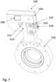
- shows another schematic perspective view of the damper of the preceding figures mounted within the surgical imaging device of
Fig. 5 ; - Fig. 8
- shows the damper inside the surgical imaging device as in
Fig. 6 and7 in a schematic sectional view; - Fig. 9
- shows another schematic sectional view of the damper inside the surgical imaging device as in
Fig. 6 and7 ; - Fig. 10
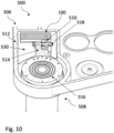
- shows a schematic sectional view of the surgical imaging device with the damper of the preceding figures.
- A surgical imaging device 500 (as shown in
Fig. 5 ), such as a surgical microscope, may be used in an operating room during a medical procedure. A user of thesurgical imaging device 500, like a surgeon or surgery assistant, may thereby accidentally hit parts of thesurgical imaging device 500. These parts of thesurgical imaging device 500 may comprise anarm 502 and an imageacquisition apparatus carrier 504, like an optics carrier or a camera, astand 506, and abase 508. Due to the mechanical linking, hitting of one of the aforementioned parts results in a transmission of the applied force through thesurgical imaging device 500. To suppress a shaking or movement of thesurgical imaging device 500 resulting from the transmitted force, thesurgical imaging device 500 may further comprise adamper 100 as further described in the embodiments in Fig. 1ff. -
Fig. 1 to Fig. 4 show perspective views of adamper 100 according to an embodiment.Fig. 1 and Fig 2 show thedamper 100 in an undeformed (resting or initial) state andFig. 3 and Fig 4 show the damper 100 a deformed state. - The
damper 100 comprises a stack oflayers outer layer 102, acentral layer 104, and a secondouter layer 106. Thelayers base piece 108 of thedamper 100. Linking of thelayers outer layer 102 further forms afirst end 110 of thedamper 100 configured to be connected to thestand 506 of a surgical imaging device 500 (as shown in Fig. 5ff). The secondouter layer 106 further forms asecond end 112 of thedamper 100 configured to be connected to thebase 508 of the surgical imaging device 500 (as shown in Fig. 5ff). By this connection, a pushing or pulling force exerted on thestand 506 and/or the base 508 acts on thedamper 100 as it is transmitted via theends damper 100 is configured to undergo elastic deformation in response to that pushing or pulling force such that thecentral layer 104, but not theouter layers - In a resting state (as shown in
Fig. 1 and Fig. 2 ) thedamper 100 and itscentral layer 104 remain undeformed as no or no substantial force is applied on theends surgical imaging device 500, e.g., from a user hitting parts of thesurgical imaging device 500, a movement of thestand 506 and/or the base 508 may occur. Due to the connection betweendamper 100 and thestand 506 and the base 508 a pushing or pulling force at theends first end 110 results in a deferral of the firstouter layer 102 relative to the secondouter layer 106, thereby inducing shearing deformation of the central layer 104 (as shown inFig. 3 and Fig. 4 , arrows with dashed line indicate the deformation). To remain undeformed, theouter layers central layer 104 may be made of an elastomer, preferably polyurethane, to be deformable. The deformation may occur in the direction of the force, so that thecentral layer 104 may undergo shearing deformation coaxially to a displacement of thefirst end 110. In further embodiments other materials for thecentral layer 104 and/or theouter layers outer layers central layer 104 in response to the force. - The deferral of the first
outer layer 102 relative to the secondouter layer 106 may thereby be limited to 2 mm. Such deferral of maximum 2 mm may translate to a maximum movement of parts of the surgical imaging device of about 20 mm in the direction of the force. Such parts may be anarm 502 and/or an imageacquisition apparatus carrier 504, e.g., a camera, optics carrier, or the like, of thesurgical imaging device 500. Hence, in a scenario where the arm and/or imageacquisition apparatus carrier 504 of thesurgical imaging device 500 are hit (accidentally) by a user and undergo a typical displacement of 2 to 3 mm, the resulting displacement of thedamper 100 would range between 0.2 to 0.3 mm. However, it is understood that the deferral of thedamper 100 and the related displacement of parts of thesurgical imaging device 500 may not be limited to a ratio of 1:10, but other ratios may be included by this disclosure in further embodiments. - Furthermore, the
central layer 104 is configured to undergo deshearing following shearing deformation to return from a deformed state, which equals a sheared state of the damper 100 (seeFig. 3 and Fig. 4 ), to an undeformed state, which equals an unsheared state of the damper 100 (seeFig. 1 and Fig. 2 ). In an unsheared or undeformed state, the deferral of theouter layers central layer 104 can repeatedly undergo shearing and deshearing in response to reoccurring pushing or pulling forces applied to theends central layer 104 because of the material properties of thecentral layer 104. Hence, use of an elastic material, such as polyurethane or materials of similar properties, may be preferred for thecentral layer 104. By returning to its desheared, undeformed state, thedamper 100 may act on thestand 506 and/or thebase 508 of thesurgical imaging device 500 such that thesurgical imaging device 500 may return to a steady state after the damper-deforming impact has occurred. This return to the steady state of thesurgical imaging device 500 may only take one to a few seconds after the impact and with few or no extra cycles of back-and-forth movement of therespective parts stand 506 and/or thebase 508 of thesurgical imaging device 500. Thereby, thesurgical imaging device 500 becomes usable again instantly or quickly after an impact has occurred. -
Fig. 6 shows a perspective view of adamper 100 mounted within asurgical imaging device 500. Thesurgical imaging device 500 may comprise afixation element 510 for fixing thefirst end 110 of thedamper 100 to ahousing 512 of astand 506 of thesurgical imaging device 500. Thesurgical imaging device 500 may further comprise afurther fixation element 514 for fixing thesecond end 112 of thedamper 100 to aconnector part 516 of abase 508 of thesurgical imaging device 500, with theconnector part 516 configured to connect the base 508 with thestand 506. And thesurgical imaging device 500 may comprise anaxis 518 configured to movably connect thefirst end 110 and thesecond end 112. Thereby, both ends 110, 112 are extending from thesame side 114 of thebase piece 108 of thedamper 100. Thesecond end 112 is configured to be movably connected to thefirst end 110. The movement of theends axis 518 in the direction of the force. Thefixation elements ends screws 520 or a boltedconnection 522, which may be gearing intorespective openings 116 of theends 110, 112 (see alsoFig. 1 andFig. 3 ). By that thedamper 100 may be mounted easily inside thesurgical imaging device 500. - The
surgical imaging device 500 may further comprise an image acquisition apparatus carrier 504 (seeFig. 5 ), such as a camera and/or an optics carrier, and an arm 502 (seeFig. 5 ). Thedamper 100 is thereby configured to undergo elastic deformation coaxially to a force exerted on the imageacquisition apparatus carrier 504 and/or thearm 502. The force may be caused by a mechanical impact, such as a user (accidentally) hitting the imageacquisition apparatus carrier 504 and/or thearm 502. The force is then transmitted through thesurgical imaging device 500 as the imageacquisition apparatus carrier 504, thearm 502, thestand 506, and the base 508 are mechanically linked. Therefore, an impact on the imageacquisition apparatus carrier 504 and/or thearm 502 is eventually transmitted to thedamper 100, which is connected to thestand 506 and the base 508 with itsends -
Fig. 7 shows another perspective view of thedamper 100 in the context of thesurgical imaging device 500. Thefixation element 510 is positioned at thefirst end 110 and thefurther fixation element 514 at thesecond end 112 with theaxis 518 connecting both ends 110, 112. This is allowing for movement of theends axis 518 in the direction of the force. -
Fig. 8 and Fig. 9 show schematic sectional views of adamper 100 withFig. 8 showing a top section view andFig. 9 showing a side section view. The section plane is located at the center of the axis 518 (indicated by dashed lines inFig. 8 and Fig. 9 ). In the depicted embodiment, thefirst end 110 is configured to be fixed at thestand 506 by thefixation element 510. Thesecond end 112 is configured to be fixed at the base 508 by thefurther fixation element 514. Thesecond end 112 is further configured to be mounted on theaxis 518, with theaxis 518 being configured to engage with thefixation element 510 in such way that during deformation thefirst end 110 is displaced along theaxis 518 thereby deferring the firstouter layer 102 in direction of the force. Thefixation elements 510 is attached to theend 110 by twoscrews 520. Thefurther fixation element 514 is attached to thesecond end 112 by a boltedconnection 522 along with theaxis 518. In further embodiments the same or different fixation means may be utilized to attach thefixation elements ends fixation element 510 may comprise acavity 524. - The
cavity 524 may allow for an at least partial take up of thefurther fixation element 514 and/orparts 526 of the boltedconnection 522 when thefirst end 110 is displaced along theaxis 518 towards thesecond end 112. By this a compact arrangement of thedamper 100 inside thesurgical imaging device 500 is achieved. Theaxis 518 may further comprise amechanical stop 528. Themechanical stop 528 is positioned opposite of thesecond end 112 and thefixation elements mechanical stop 528 thereby limits the displacement of thefirst end 110 along theaxis 518. In the depicted embodiment the displacement may be limited such that the deferral of theouter layers mechanical stop 528 on theaxis 518 may be used in further embodiments. The use of themechanical stop 528 may prevent over-shearing of thecentral layer 104 and by that damaging of thedamper 100. -
Fig. 10 shows a sectional view of asurgical imaging device 500. The section plane is at the center of the axis 518 (similar toFig. 8 ). In the embodiment, thefixation element 510 is fixing thefirst end 110 of thedamper 100 to thehousing 512 of astand 506. Thehousing 512 thereby comprises acompartment 530 for taking up thedamper 100. Thefurther fixation element 514 is fixing thesecond end 112 of thedamper 100 to theconnector part 516 of thebase 508. Theconnector part 516 is configured to connect the base 508 with thestand 506. A movement of thestand 506 and/or thebase 508 exerts a pushing or pulling force on at least one of theends damper 100, hence, leading to its deformation. - As used herein the term "and/or" includes any and all combinations of one or more of the associated listed items and may be abbreviated as "/".
- Although some aspects have been described in the context of an apparatus, it is clear that these aspects also represent a description of the corresponding method, where a block or device corresponds to a method step or a feature of a method step. Analogously, aspects described in the context of a method step also represent a description of a corresponding block or item or feature of a corresponding apparatus.
-
- 100
- Damper
- 102
- Outer layer
- 104
- Central layer
- 106
- Outer layer
- 108
- Base piece
- 110
- First end
- 112
- Second end
- 114
- Side
- 116
- Opening
- 500
- Surgical imaging device
- 502
- Arm
- 504
- Image acquisition apparatus carrier
- 506
- Stand
- 508
- Base
- 510
- Fixation element
- 512
- Housing
- 514
- Fixation element
- 516
- Connector part
- 518
- Axis
- 520
- Screw
- 522
- Bolted connection
- 524
- Cavity
- 526
- Part
- 528
- Mechanical stop
- 530
- Compartment
Claims (10)
- Damper for a surgical imaging device (500), the damper (100) comprising a stack of layers (102, 104, 106) comprising: a first outer layer (102), a central layer (104), and a second outer layer (106); wherein the layers are linked to form a base piece (108) of the damper (100); wherein the first outer layer (102) further forms a first end (110) of the damper (100) configured to be connected to a stand (506) of the surgical imaging device (500) and the second outer layer (106) further forms a second end (112) of the damper (100) configured to be connected to a base (508) of the surgical imaging device (500); wherein the damper (100) is configured to undergo elastic deformation in response to a pushing or pulling force exhibited on one of the ends (110, 112) such that the central layer (104), but not the outer layers (102, 106), undergo elastic deformation; wherein application of the force to the first end (110) causes a deferral of the first outer layer (104) relative to the second outer layer (106), thereby inducing shearing deformation of the central layer (104).
- Damper according to claim 1, wherein the deferral is limited to 2 mm.
- Damper according to claim 1 or 2, wherein the ends (110, 112) are extending from the same side (114) of the base piece (108) of the damper (100), wherein the second end (112) is configured to be movably connected to the first end (110).
- Damper according to claim 3, wherein the first end (110) is configured to be fixed at the stand (506) by a fixation element (510); wherein the second end (112) is configured to be fixed at the base (508) by at least one further fixation element (514); wherein the second end (112) is further configured to be mounted on an axis (518), with the axis (518) being configured to engage with the fixation element (510) in such way that during deformation the first end (110) is displaced along the axis (518) thereby deferring the first outer layer (102) in direction of the force.
- Damper according to claim 3 or 4, wherein the central layer (104) undergoes shearing deformation coaxially to a displacement of the first end (110).
- Damper according to one of the preceding claims, wherein the outer layers (102, 106) are made of sheet metal, wherein the central layer (104) is made of an elastomer, preferably polyurethane.
- Damper according to one of the preceding claims, the central layer (104) is configured to undergo deshearing following shearing deformation to return from a deformed state to an undeformed state.
- Surgical imaging device comprising a stand (506), a base (508), and a damper (100) according to one of the preceding claims.
- Surgical imaging device according to claim 8, the surgical imaging device (500) further comprising a fixation element (510) for fixing a first end (110) of the damper (100) to a housing (512) of the stand (506), a further fixation element (514) for fixing a second end (112) of the damper (100) to a connector part (516) of the base (508), with the connector part (516) configured to connect the base (508) with the stand (506), and an axis (518) configured to movably connect the first end (110) and the second end (112).
- Surgical imaging device according to claim 8 or 9, the surgical imaging device (500) further comprising an image acquisition apparatus carrier (504) and an arm (502), wherein the damper (100) is configured to undergo elastic deformation coaxially to a force exerted on the image acquisition apparatus carrier (504) and/or the arm (502).
Applications Claiming Priority (1)
| Application Number | Priority Date | Filing Date | Title |
|---|---|---|---|
| DE102023125411.1A DE102023125411A1 (en) | 2023-09-19 | 2023-09-19 | Damper and surgical imaging device |
Publications (2)
| Publication Number | Publication Date |
|---|---|
| EP4528347A1 true EP4528347A1 (en) | 2025-03-26 |
| EP4528347B1 EP4528347B1 (en) | 2026-05-20 |
Family
ID=92882417
Family Applications (1)
| Application Number | Title | Priority Date | Filing Date |
|---|---|---|---|
| EP24201352.2A Active EP4528347B1 (en) | 2023-09-19 | 2024-09-19 | DAMPER AND SURGICAL IMAGING DEVICE |
Country Status (5)
| Country | Link |
|---|---|
| US (1) | US20250090264A1 (en) |
| EP (1) | EP4528347B1 (en) |
| JP (1) | JP2025044167A (en) |
| CN (1) | CN119664843A (en) |
| DE (1) | DE102023125411A1 (en) |
Citations (6)
| Publication number | Priority date | Publication date | Assignee | Title |
|---|---|---|---|---|
| WO1998053244A1 (en) * | 1997-05-20 | 1998-11-26 | Leica Mikroskopie Systeme Ag | Microscope stand, especially for an operation microscope |
| US20020020788A1 (en) * | 2000-08-16 | 2002-02-21 | Juergen Pensel | Folding stand |
| US20020166942A1 (en) * | 2001-03-30 | 2002-11-14 | Andrzej Metelski | Microscope stand, in particular for a surgical microscope |
| US20040262866A1 (en) * | 2003-06-27 | 2004-12-30 | Carl-Zeiss-Stiftung Trading As Carl Zeiss | Displaceable support stand |
| JP6159706B2 (en) * | 2014-12-16 | 2017-07-05 | 株式会社ポリシス | Vibration reduction device |
| US10251717B2 (en) * | 2014-08-01 | 2019-04-09 | Intuitive Surgical Operations, Inc. | Damping a telesurgical system |
Family Cites Families (1)
| Publication number | Priority date | Publication date | Assignee | Title |
|---|---|---|---|---|
| US8474572B2 (en) * | 2011-08-25 | 2013-07-02 | General Electric Company | Apparatus and method to attenuate vibration and acoustic noise |
-
2023
- 2023-09-19 DE DE102023125411.1A patent/DE102023125411A1/en active Granted
-
2024
- 2024-09-18 JP JP2024160762A patent/JP2025044167A/en active Pending
- 2024-09-18 CN CN202411301387.4A patent/CN119664843A/en active Pending
- 2024-09-19 US US18/889,490 patent/US20250090264A1/en active Pending
- 2024-09-19 EP EP24201352.2A patent/EP4528347B1/en active Active
Patent Citations (6)
| Publication number | Priority date | Publication date | Assignee | Title |
|---|---|---|---|---|
| WO1998053244A1 (en) * | 1997-05-20 | 1998-11-26 | Leica Mikroskopie Systeme Ag | Microscope stand, especially for an operation microscope |
| US20020020788A1 (en) * | 2000-08-16 | 2002-02-21 | Juergen Pensel | Folding stand |
| US20020166942A1 (en) * | 2001-03-30 | 2002-11-14 | Andrzej Metelski | Microscope stand, in particular for a surgical microscope |
| US20040262866A1 (en) * | 2003-06-27 | 2004-12-30 | Carl-Zeiss-Stiftung Trading As Carl Zeiss | Displaceable support stand |
| US10251717B2 (en) * | 2014-08-01 | 2019-04-09 | Intuitive Surgical Operations, Inc. | Damping a telesurgical system |
| JP6159706B2 (en) * | 2014-12-16 | 2017-07-05 | 株式会社ポリシス | Vibration reduction device |
Also Published As
| Publication number | Publication date |
|---|---|
| EP4528347B1 (en) | 2026-05-20 |
| DE102023125411A1 (en) | 2025-03-20 |
| JP2025044167A (en) | 2025-04-01 |
| US20250090264A1 (en) | 2025-03-20 |
| CN119664843A (en) | 2025-03-21 |
Similar Documents
| Publication | Publication Date | Title |
|---|---|---|
| US6514239B2 (en) | Medical instrument holding apparatus | |
| JP6833911B2 (en) | Cannula with sensors to measure patient wall strength | |
| CN113288430B (en) | Sterile plate assembly, surgical instrument, power box and surgical robot system | |
| US8629900B2 (en) | 3D endoscope | |
| EP2253289A3 (en) | Offset remote center manipulator | |
| EP2133036A1 (en) | Medical manipulator device and actuator suitable for the same | |
| JP5208938B2 (en) | Improved impactor | |
| JP2004081867A (en) | Surgical console | |
| EP1290982A3 (en) | Modularity system for computer assisted surgery | |
| US20250090264A1 (en) | Damper and Surgical Imaging Device | |
| JP2024073486A (en) | Surgical Robots | |
| CN110559078B (en) | Sleeve fixing assembly for minimally invasive surgery system | |
| US6247963B1 (en) | Connection unit for use in a medical workplace | |
| KR20070014536A (en) | 4-joint support assembly for supporting the monitor of ultrasonic diagnostic device | |
| Stoianovici et al. | A novel mechanical transmission applied to percutaneous renal access | |
| Kim et al. | A suction-fixing, stiffness-tunable liver manipulator for laparoscopic surgeries | |
| Ikuta et al. | Hyper-finger for remote minimally invasive surgery in deep area | |
| CN219109732U (en) | Sterile adapter | |
| JP2001025472A (en) | Supporting device for medical optical instrument | |
| EP3034028A1 (en) | A multi-degree of freedom surgical instrument for minimally invasive surgery | |
| JP6656237B2 (en) | Surgical microscope device and surgical microscope system | |
| Halpern | The difficult laparoscopy | |
| KR102097747B1 (en) | Jig device for repeating equipment | |
| Nakamura et al. | Multi-DOF forceps manipulator system for laparoscopic surgery | |
| US20170097488A1 (en) | Surgical microscope stand |
Legal Events
| Date | Code | Title | Description |
|---|---|---|---|
| PUAI | Public reference made under article 153(3) epc to a published international application that has entered the european phase |
Free format text: ORIGINAL CODE: 0009012 |
|
| STAA | Information on the status of an ep patent application or granted ep patent |
Free format text: STATUS: THE APPLICATION HAS BEEN PUBLISHED |
|
| AK | Designated contracting states |
Kind code of ref document: A1 Designated state(s): AL AT BE BG CH CY CZ DE DK EE ES FI FR GB GR HR HU IE IS IT LI LT LU LV MC ME MK MT NL NO PL PT RO RS SE SI SK SM TR |
|
| STAA | Information on the status of an ep patent application or granted ep patent |
Free format text: STATUS: REQUEST FOR EXAMINATION WAS MADE |
|
| 17P | Request for examination filed |
Effective date: 20250926 |
|
| GRAP | Despatch of communication of intention to grant a patent |
Free format text: ORIGINAL CODE: EPIDOSNIGR1 |
|
| STAA | Information on the status of an ep patent application or granted ep patent |
Free format text: STATUS: GRANT OF PATENT IS INTENDED |
|
| RIC1 | Information provided on ipc code assigned before grant |
Ipc: G02B 7/00 20210101AFI20251203BHEP Ipc: G02B 21/00 20060101ALI20251203BHEP |
|
| INTG | Intention to grant announced |
Effective date: 20251217 |
|
| GRAS | Grant fee paid |
Free format text: ORIGINAL CODE: EPIDOSNIGR3 |
|
| GRAA | (expected) grant |
Free format text: ORIGINAL CODE: 0009210 |
|
| STAA | Information on the status of an ep patent application or granted ep patent |
Free format text: STATUS: THE PATENT HAS BEEN GRANTED |