EP4528321A1 - Lidar apparatus and control method thereof - Google Patents
Lidar apparatus and control method thereof Download PDFInfo
- Publication number
- EP4528321A1 EP4528321A1 EP24199550.5A EP24199550A EP4528321A1 EP 4528321 A1 EP4528321 A1 EP 4528321A1 EP 24199550 A EP24199550 A EP 24199550A EP 4528321 A1 EP4528321 A1 EP 4528321A1
- Authority
- EP
- European Patent Office
- Prior art keywords
- peak value
- histogram
- processor
- measurement count
- distance
- Prior art date
- Legal status (The legal status is an assumption and is not a legal conclusion. Google has not performed a legal analysis and makes no representation as to the accuracy of the status listed.)
- Granted
Links
Images



Classifications
-
- G—PHYSICS
- G01—MEASURING; TESTING
- G01S—RADIO DIRECTION-FINDING; RADIO NAVIGATION; DETERMINING DISTANCE OR VELOCITY BY USE OF RADIO WAVES; LOCATING OR PRESENCE-DETECTING BY USE OF THE REFLECTION OR RERADIATION OF RADIO WAVES; ANALOGOUS ARRANGEMENTS USING OTHER WAVES
- G01S7/00—Details of systems according to groups G01S13/00, G01S15/00, G01S17/00
- G01S7/48—Details of systems according to groups G01S13/00, G01S15/00, G01S17/00 of systems according to group G01S17/00
- G01S7/483—Details of pulse systems
- G01S7/486—Receivers
- G01S7/487—Extracting wanted echo signals, e.g. pulse detection
- G01S7/4873—Extracting wanted echo signals, e.g. pulse detection by deriving and controlling a threshold value
-
- G—PHYSICS
- G01—MEASURING; TESTING
- G01S—RADIO DIRECTION-FINDING; RADIO NAVIGATION; DETERMINING DISTANCE OR VELOCITY BY USE OF RADIO WAVES; LOCATING OR PRESENCE-DETECTING BY USE OF THE REFLECTION OR RERADIATION OF RADIO WAVES; ANALOGOUS ARRANGEMENTS USING OTHER WAVES
- G01S7/00—Details of systems according to groups G01S13/00, G01S15/00, G01S17/00
- G01S7/48—Details of systems according to groups G01S13/00, G01S15/00, G01S17/00 of systems according to group G01S17/00
- G01S7/4808—Evaluating distance, position or velocity data
-
- G—PHYSICS
- G01—MEASURING; TESTING
- G01S—RADIO DIRECTION-FINDING; RADIO NAVIGATION; DETERMINING DISTANCE OR VELOCITY BY USE OF RADIO WAVES; LOCATING OR PRESENCE-DETECTING BY USE OF THE REFLECTION OR RERADIATION OF RADIO WAVES; ANALOGOUS ARRANGEMENTS USING OTHER WAVES
- G01S17/00—Systems using the reflection or reradiation of electromagnetic waves other than radio waves, e.g. lidar systems
- G01S17/02—Systems using the reflection of electromagnetic waves other than radio waves
- G01S17/06—Systems determining position data of a target
- G01S17/08—Systems determining position data of a target for measuring distance only
-
- G—PHYSICS
- G01—MEASURING; TESTING
- G01S—RADIO DIRECTION-FINDING; RADIO NAVIGATION; DETERMINING DISTANCE OR VELOCITY BY USE OF RADIO WAVES; LOCATING OR PRESENCE-DETECTING BY USE OF THE REFLECTION OR RERADIATION OF RADIO WAVES; ANALOGOUS ARRANGEMENTS USING OTHER WAVES
- G01S7/00—Details of systems according to groups G01S13/00, G01S15/00, G01S17/00
- G01S7/48—Details of systems according to groups G01S13/00, G01S15/00, G01S17/00 of systems according to group G01S17/00
- G01S7/4802—Details of systems according to groups G01S13/00, G01S15/00, G01S17/00 of systems according to group G01S17/00 using analysis of echo signal for target characterisation; Target signature; Target cross-section
-
- G—PHYSICS
- G01—MEASURING; TESTING
- G01S—RADIO DIRECTION-FINDING; RADIO NAVIGATION; DETERMINING DISTANCE OR VELOCITY BY USE OF RADIO WAVES; LOCATING OR PRESENCE-DETECTING BY USE OF THE REFLECTION OR RERADIATION OF RADIO WAVES; ANALOGOUS ARRANGEMENTS USING OTHER WAVES
- G01S7/00—Details of systems according to groups G01S13/00, G01S15/00, G01S17/00
- G01S7/48—Details of systems according to groups G01S13/00, G01S15/00, G01S17/00 of systems according to group G01S17/00
- G01S7/483—Details of pulse systems
-
- G—PHYSICS
- G01—MEASURING; TESTING
- G01S—RADIO DIRECTION-FINDING; RADIO NAVIGATION; DETERMINING DISTANCE OR VELOCITY BY USE OF RADIO WAVES; LOCATING OR PRESENCE-DETECTING BY USE OF THE REFLECTION OR RERADIATION OF RADIO WAVES; ANALOGOUS ARRANGEMENTS USING OTHER WAVES
- G01S7/00—Details of systems according to groups G01S13/00, G01S15/00, G01S17/00
- G01S7/48—Details of systems according to groups G01S13/00, G01S15/00, G01S17/00 of systems according to group G01S17/00
- G01S7/491—Details of non-pulse systems
-
- G—PHYSICS
- G05—CONTROLLING; REGULATING
- G05B—CONTROL OR REGULATING SYSTEMS IN GENERAL; FUNCTIONAL ELEMENTS OF SUCH SYSTEMS; MONITORING OR TESTING ARRANGEMENTS FOR SUCH SYSTEMS OR ELEMENTS
- G05B19/00—Program-control systems
- G05B19/02—Program-control systems electric
- G05B19/04—Program control other than numerical control, i.e. in sequence controllers or logic controllers
Definitions
- Exemplary embodiments of the present disclosure relate to a lidar apparatus and a control method thereof, and more particularly, to a lidar apparatus and a control method thereof, which may set a measurement count differently depending on a distance range to an object when generating a histogram of received signals to measure a distance to an object by transmitting and receiving a laser, or may set a measurement count by comparing the histogram's peak value and limit value while measuring the distance.
- a lidar sensor detects an object by emitting light and receiving a signal, which is the emitted light reflected from the object, and calculates a distance to the object by measuring the time interval between transmitted and received signals.
- lidar sensor has been applied to various devices, including vehicles, drones, and robot vacuum cleaners.
- a transmitter emitting laser light and a receiver receiving reflected light form a two-dimensional array.
- the transmitter and the receiver, emitting and receiving light, respectively operate constantly using the entire array, thereby consuming more power than necessary regardless of a target to detect.
- a 2D lidar sensor composed of a two-dimensional array is effective in object detection and distance calculation using SPAD.
- the 2D lidar sensor due to its high sensitivity to light, the 2D lidar sensor is susceptible to significant internal noise and noise interference from outdoor light.
- a distance to an object is measured by detecting a peak value and calculating Time of Flight (ToF).
- TOF Time of Flight
- Various embodiments are directed to a lidar apparatus and a control method thereof, which may set a measurement count differently depending on a distance range to an object when generating a histogram of received signals to measure a distance to an object by transmitting and receiving a laser, or may set a measurement count by comparing the histogram's peak value and limit value while measuring the distance.
- a lidar apparatus includes: a transmission and reception module transmitting a laser signal and receiving a reflected signal reflected from an object; an output module outputting a calculated object distance; a memory storing a measurement count allocated for each distance range; and a processor operatively coupled to the transmission and reception module, the output module, and the memory, wherein after repeating a process of generating a histogram by accumulating the reflected signals received through the transmission and reception module for a set measurement count, the processor calculates an object distance based on a peak value of the histogram and outputs the calculated object distance through the output module, and then modifies, based on the object distance, the set measurement count based on the measurement count allocated for each distance range, to repeat the process of calculating the object distance.
- the measurement count allocated for each distance range is an optimized measurement count based on a magnitude of the output of the transmission and reception module, and a measurement count increases as the distance increases.
- a lidar apparatus in another embodiment, includes: a transmission and reception module transmitting a laser signal and receiving a reflected signal reflected from an object; an output module outputting a calculated object distance; a memory storing a limit peak value of the histogram; and a processor operatively coupled to the transmission and reception module, the output module, and the memory, wherein the processor repeats a process of generating the histogram by accumulating the reflected signals received through the transmission and reception module, and if a peak value of the histogram is greater than or equal to the limit peak value of the same, the processor calculates an object distance based on the peak value of the histogram and outputs the calculated object distance through the output module.
- a lidar apparatus includes: a transmission and reception module transmitting a laser signal and receiving a reflected signal reflected from an object; an output module outputting a calculated object distance; a memory storing a measurement count allocated for each distance range and a limit peak value of a histogram; and a processor operatively coupled to the transmission and reception module, the output module, and the memory, wherein after repeating a process of generating the histogram by accumulating the reflected signals received through the transmission and reception module for a set measurement count, the processor compares a peak value of the histogram with the limit peak value of the same, and if the peak value is less than the limit peak value, the processor repeats the process of generating the histogram; and if the comparison of the peak value and the limit peak value determines that the peak value is greater than or equal to the limit peak value, the processor calculates an object distance based on the peak value of the histogram and outputs the calculated object distance through the output module.
- a control method of a lidar apparatus includes: generating a histogram, by a processor, by accumulating reflected signals received through a transmission and reception module; repeating, by the processor, a process of the generating of the histogram for a set measurement count; after repeating, by the processor, the generating of the histogram for the set number of measurement, calculating, by the processor, an object distance based on a peak value of the histogram and outputting, by the processor, the calculated object distance; and modifying, by the processor, based on the object distance, the set measurement count based on a measurement count allocated for each distance range.
- the measurement count allocated for each distance range is an optimized measurement count based on a magnitude of the output of the transmission and reception module, and a measurement count increases as the distance increases.
- a control method of a lidar apparatus includes: repeating, by a processor, a process of generating a histogram by accumulating reflected signals received through a transmission and reception module; while repeating, by the processor, the process of generating the histogram, comparing, by the processor, a peak value of the histogram with a limit peak value of the same ; and calculating, by the processor, an object distance based on the peak value of the histogram and outputting the calculated object distance if the comparison of the peak value and the limit peak value determines that the peak value is greater than or equal to the limit peak value.
- a control method of a lidar apparatus includes: generating a histogram, by a processor, by accumulating reflected signals received through a transmission and reception module; repeating, by the processor, a process of the generating of the histogram for a set measurement count; after repeating, by the processor, the generating of the histogram for the set number of measurement, comparing, by the processor, a peak value of the histogram with a limit peak value of the same; repeating, by the processor, the process of the generating of the histogram if the comparison of the peak value and the limit peak value determines that the peak value is less than the limit peak value; and calculating, by the processor, an object distance based on a peak value of the histogram and outputting, by the processor, the calculated object distance if the comparison of the peak value and the limit peak value determines that the peak value is greater than or equal to the limit peak value.
- control method of a lidar apparatus further includes modifying, by the processor, based on the object distance, the set measurement count based on a measurement count allocated for each distance range.
- the lidar apparatus and the control method thereof may set a measurement count differently depending on a distance range to an object when generating a histogram of received signals to measure a distance to an object by transmitting and receiving a laser, or may set a measurement count by comparing the histogram's peak value and limit value while measuring the distance.
- the lidar apparatus and the control method thereof may improve performance of distance measurement by preventing a distance error as well as reduce unnecessary heat generation and power consumption by the transmission and reception module.
- FIG. 1 is a block diagram showing a lidar apparatus according to an embodiment of the present disclosure.
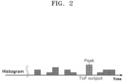
- FIG. 2 is an exemplary view showing a histogram generated through the lidar apparatus according to an embodiment of the present disclosure.
- the lidar apparatus may include a transmission and reception module 40, an output module 10, a memory 20, and a processor 30.
- the transmission and reception module 40 may transmit a laser signal and receive a reflected signal reflected from an object 50.
- the output module 10 may output a value of Time of Flight (ToF) of an object distance calculated by the lidar apparatus.
- ToF Time of Flight
- the memory 20 stores various types of software and data generated in the process of executing an operating system or application (program or applet) for operating the lidar apparatus.
- the memory 20 refers to both a non-volatile storage device that continues to maintain stored information even when no power is supplied and a volatile storage device that requires power to maintain stored information.
- the memory 20 may perform the function of temporarily or permanently storing data processed by the processor 30.
- the memory 20 may include a magnetic storage medium or a flash storage medium in addition to a volatile storage device that requires power to maintain stored information, but the scope of the present disclosure is not limited thereto.
- the memory 20 may store a measurement count allocated for each distance range, or may store a limit peak value of the histogram.
- the measurement count allocated for each distance range is an optimized measurement count based on a magnitude of the output of the transmission and reception module 40, and a measurement count may increase as the distance increases.
- the number and interval of distance ranges may be set differently according to user customization.
- the limit peak value may be set to a saturation value that may be processed by the processor 30 when the histogram is generated, or may be set arbitrarily by a user.
- the processor 30 is a configuration that is operatively coupled to the transmission and reception module 40 and the memory 10 and controls the overall operation of the lidar apparatus, and may be implemented as an integrated circuit or system.
- the processor 30 may operate the transmission and reception module 40 per frame and repeat a process of generating a laser signal and transmitting the same to the object 50 and receiving a reflected signal reflected from the object 50 through the transmission and reception module 40 to calculate the object distance based on a ToF value derived from a difference between the transmission time of the laser signal and the reception time of the reflected signal and output the calculated object distance through the output module 10.
- the processor 30 may repeat a process of accumulating reflected signals received through the transmission and reception module 40 for a measurement count set per frame to generate a histogram as shown in FIG. 2 .
- the processor 30 may calculate and output an object distance through the output module 10.
- the processor 30 may modify the set measurement count based on the measurement count allocated for each distance range stored in the memory 20. Then, in a next frame, the processor 30 may generate the histogram based on the modified measurement count to calculate the object distance.
- Varying, based on the object distance, the set measurement count for each distance range in this way may address the issue of reduced distance accuracy in a specific distance zone, thereby improving reliability of distance measurement.
- the processor 30 may accumulate reflected signals received through the transmission and reception module 40 per frame to repeat the process of generating a histogram. If a peak value of the histogram is greater than or equal to a limit peak value of the same, the processor 30 may calculate and output an object distance based on a peak value of the histogram.
- the object distance is calculated based on the peak value, thereby resolving the difficulty in distance measurement caused by a saturated or insufficiently secured peak value.
- the processor 30 may repeat a process of accumulating reflected signals received through the transmission and reception module 40 for a measurement count set per frame to generate a histogram as shown in FIG. 2
- the processor 30 may modify, based on the calculated object distance, the set measurement count based on the measurement count allocated for each distance range stored in the memory 20. Then, in a next frame, the processor 30 may generate the histogram based on the modified measurement count to calculate the object distance.
- Varying, based on the object distance, the set measurement count for each distance range in this way may address the issue of reduced distance accuracy in a specific distance zone. Furthermore, after the histogram is repeatedly generated for the set measurement count, additional measurements may be made if the peak value is insufficient, thereby increasing accuracy of distance measurement.
- the lidar apparatus may set a measurement count differently depending on a distance range to an object when generating a histogram of received signals to measure a distance to an object by transmitting and receiving a laser, or may set a measurement count by comparing the histogram's peak value and limit value while measuring the distance.
- the lidar apparatus may improve performance of distance measurement by preventing a distance error as well as reduce unnecessary heat generation and power consumption by the transmission and reception module.
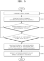
- FIG. 3 is a flowchart illustrating a control method of a lidar apparatus according to a first embodiment of the present disclosure.
- the processor 30 first operates the transmission and reception module 40 to transmit a laser signal to the object 50 to measure a distance to the object 50 (S310).
- the processor 30 After transmitting the laser signal to the object 50 in step S310, the processor 30 receives a reflected signal reflected from the object 50 through the transmission and reception module 40 and accumulates reflected signals to generate a histogram as shown in FIG. 2 (S320).
- step S330 If the comparison of the measurement count with the set measurement count determines that the measurement count does not exceed the set measurement count in step S330, the processor 30 returns to step S310 and repeats a process of generating the histogram.
- the processor 30 calculates an object distance based on a peak value of the histogram and outputs the calculated object distance through the output module 10 (S340).
- the measurement count allocated for each distance range is an optimized measurement count based on a magnitude of the output of the transmission and reception module 40, and a measurement count may increase as the distance increases.
- the number and interval of distance ranges may be set differently according to user customization.
- Varying, based on the object distance, the set measurement count for each distance range in this way may address the issue of reduced distance accuracy in a specific distance zone, thereby improving reliability of distance measurement.
- FIG. 4 is a flowchart illustrating a control method of a lidar apparatus according to a second embodiment of the present disclosure.
- the processor 30 first operates the transmission and reception module 40 to transmit a laser signal to the object 50 to measure a distance to the object 50 (S410).
- the processor 30 After transmitting the laser signal to the object 50 in step S410, the processor 30 receives a reflected signal reflected from the object 50 through the transmission and reception module 40 and accumulates reflected signals to generate a histogram as shown in FIG. 2 (S420).
- the processor 30 After generating the histogram in step S420, the processor 30 compares a peak value of the histogram and a limit peak value of the same (S430).
- the limit peak value may be set to a saturation value that may be processed by the processor 30 when the histogram is generated, or may be set arbitrarily by a user.
- step S430 If the comparison of the measurement count with the set measurement count determines that the peak value of the histogram is less than the limit peak value of the same in step S430, the processor 30 returns to step S410 and repeats the process of generating the histogram.
- the processor 30 calculates an object distance based on the peak value of the histogram and outputs the calculated object distance through the output module 10 (S440).
- the object distance is calculated based on the peak value, thereby resolving the difficulty in distance measurement caused by a saturated or insufficiently secured peak value.
- FIG. 5 is a flowchart illustrating a control method of a lidar apparatus according to a third embodiment of the present disclosure.
- the processor 30 first operates the transmission and reception module 40 to transmit a laser signal to the object 50 to measure a distance to the object 50 (S510).
- the processor 30 After transmitting the laser signal to the object 50 in step S510, the processor 30 receives a reflected signal reflected from the object 50 through the transmission and reception module 40 and accumulates reflected signals to generate a histogram as shown in FIG. 2 (S520).
- the processor 30 After generating the histogram in step S520, the processor 30 counts a measurement count to determine whether the measurement count exceeds a set measurement count (S530).
- step S530 If the comparison of the measurement count with the set measurement count determines that the measurement count does not exceed the set measurement count in step S530, the processor 30 returns to step S510 and repeats the process of generating the histogram.
- the processor 30 compares a peak value of the histogram and a limit peak value of the same (S540).
- the limit peak value may be set to a saturation value that may be processed by the processor 30 when the histogram is generated, or may be set arbitrarily by a user.
- step S540 If the comparison of the measurement count with the set measurement count determines that the peak value of the histogram is less than the limit peak value of the same in step S540, the processor 30 returns to step S510 and repeats the process of generating the histogram.
- the processor 30 calculates an object distance based on the peak value of the histogram and outputs the calculated object distance through the output module 10 (S550).
- the processor 30 modifies, based on the calculated object distance, the set measurement count based on a measurement count allocated for each distance range stored in the memory 20 (S560).
- Varying, based on the object distance, the set measurement count for each distance range in this way may address the issue of reduced distance accuracy in a specific distance zone. Furthermore, after the histogram is repeatedly generated for the set measurement count, additional measurements may be made if the peak value is insufficient, thereby increasing accuracy of distance measurement.
- the control method of the lidar apparatus may set a measurement count differently depending on a distance range to an object when generating a histogram of received signals to measure a distance to an object by transmitting and receiving a laser, or may set a measurement count by comparing the histogram's peak value and limit value while measuring the distance.
- the lidar apparatus may improve performance of distance measurement by preventing a distance error as well as reduce unnecessary heat generation and power consumption by the transmission and reception module.
- a device may be implemented with appropriate hardware, software, and firmware, etc.
- a method may be implemented in a device, such as a processor, which generally refers to a processing device including, for example, a computer, microprocessor, integrated circuit, or programmable logic device. Processors also include communication devices such as computers, cell phones, personal digital assistants (PDAs) and other devices that facilitate communication of information between end-users.
- PDAs personal digital assistants
Landscapes
- Engineering & Computer Science (AREA)
- Physics & Mathematics (AREA)
- General Physics & Mathematics (AREA)
- Computer Networks & Wireless Communication (AREA)
- Radar, Positioning & Navigation (AREA)
- Remote Sensing (AREA)
- Electromagnetism (AREA)
- Automation & Control Theory (AREA)
- Optical Radar Systems And Details Thereof (AREA)
- Measurement Of Optical Distance (AREA)
Abstract
Description
- Exemplary embodiments of the present disclosure relate to a lidar apparatus and a control method thereof, and more particularly, to a lidar apparatus and a control method thereof, which may set a measurement count differently depending on a distance range to an object when generating a histogram of received signals to measure a distance to an object by transmitting and receiving a laser, or may set a measurement count by comparing the histogram's peak value and limit value while measuring the distance.
- In general, a lidar sensor detects an object by emitting light and receiving a signal, which is the emitted light reflected from the object, and calculates a distance to the object by measuring the time interval between transmitted and received signals.
- In recent years, the lidar sensor has been applied to various devices, including vehicles, drones, and robot vacuum cleaners.
- In the lidar sensor, a transmitter emitting laser light and a receiver receiving reflected light form a two-dimensional array. In the lidar sensor, the transmitter and the receiver, emitting and receiving light, respectively, operate constantly using the entire array, thereby consuming more power than necessary regardless of a target to detect.
- The constant use of the entire array composed of the transmitter and the receiver leads to heat generation in the lidar sensor.
- If the entire array remains in a state of constant operation, accelerated degradation of the lidar sensor itself and noise may occur.
- In addition, a 2D lidar sensor composed of a two-dimensional array is effective in object detection and distance calculation using SPAD. However, due to its high sensitivity to light, the 2D lidar sensor is susceptible to significant internal noise and noise interference from outdoor light.
- To resolve these limitations, a method has been proposed to measure received data tens to hundreds of times, generate a histogram, and then detect a peak value to determine an effective value.
- The related art of the present disclosure is disclosed in
Korean Patent Application Publication No.10-2023-0105834 (published on July 12, 2023 - After a histogram is generated by accumulating multiple measured values, a distance to an object is measured by detecting a peak value and calculating Time of Flight (ToF).
- If a measurement count between frames is fixed at a high value to measure a distant object, a peak value of the histogram becomes saturated when a close object is measured, thereby making it difficult to take accurate distance measurement.
- On the other hand, if the measurement count between frames is fixed at a low value to measure a close object, a peak value of the histogram is not sufficiently secured when a distant object is measured, thereby making it difficult to take accurate distance measurement.
- For such a lidar apparatus with the fixed measurement count between frames, distance accuracy in a specific distance zone decreases, resulting in degraded performance.
- Various embodiments are directed to a lidar apparatus and a control method thereof, which may set a measurement count differently depending on a distance range to an object when generating a histogram of received signals to measure a distance to an object by transmitting and receiving a laser, or may set a measurement count by comparing the histogram's peak value and limit value while measuring the distance.
- In an embodiment, a lidar apparatus includes: a transmission and reception module transmitting a laser signal and receiving a reflected signal reflected from an object; an output module outputting a calculated object distance; a memory storing a measurement count allocated for each distance range; and a processor operatively coupled to the transmission and reception module, the output module, and the memory, wherein after repeating a process of generating a histogram by accumulating the reflected signals received through the transmission and reception module for a set measurement count, the processor calculates an object distance based on a peak value of the histogram and outputs the calculated object distance through the output module, and then modifies, based on the object distance, the set measurement count based on the measurement count allocated for each distance range, to repeat the process of calculating the object distance.
- In the present disclosure, the measurement count allocated for each distance range is an optimized measurement count based on a magnitude of the output of the transmission and reception module, and a measurement count increases as the distance increases.
- In another embodiment, a lidar apparatus includes: a transmission and reception module transmitting a laser signal and receiving a reflected signal reflected from an object; an output module outputting a calculated object distance; a memory storing a limit peak value of the histogram; and a processor operatively coupled to the transmission and reception module, the output module, and the memory, wherein the processor repeats a process of generating the histogram by accumulating the reflected signals received through the transmission and reception module, and if a peak value of the histogram is greater than or equal to the limit peak value of the same, the processor calculates an object distance based on the peak value of the histogram and outputs the calculated object distance through the output module.
- In still another embodiment, a lidar apparatus includes: a transmission and reception module transmitting a laser signal and receiving a reflected signal reflected from an object; an output module outputting a calculated object distance; a memory storing a measurement count allocated for each distance range and a limit peak value of a histogram; and a processor operatively coupled to the transmission and reception module, the output module, and the memory, wherein after repeating a process of generating the histogram by accumulating the reflected signals received through the transmission and reception module for a set measurement count, the processor compares a peak value of the histogram with the limit peak value of the same, and if the peak value is less than the limit peak value, the processor repeats the process of generating the histogram; and if the comparison of the peak value and the limit peak value determines that the peak value is greater than or equal to the limit peak value, the processor calculates an object distance based on the peak value of the histogram and outputs the calculated object distance through the output module.
- In the present disclosure, the processor modifies, based on the calculated object distance, the set measurement count based on the measurement count allocated for each distance range.
- In an embodiment, a control method of a lidar apparatus includes: generating a histogram, by a processor, by accumulating reflected signals received through a transmission and reception module; repeating, by the processor, a process of the generating of the histogram for a set measurement count; after repeating, by the processor, the generating of the histogram for the set number of measurement, calculating, by the processor, an object distance based on a peak value of the histogram and outputting, by the processor, the calculated object distance; and modifying, by the processor, based on the object distance, the set measurement count based on a measurement count allocated for each distance range.
- In the present disclosure, the measurement count allocated for each distance range is an optimized measurement count based on a magnitude of the output of the transmission and reception module, and a measurement count increases as the distance increases.
- In another embodiment, a control method of a lidar apparatus includes: repeating, by a processor, a process of generating a histogram by accumulating reflected signals received through a transmission and reception module; while repeating, by the processor, the process of generating the histogram, comparing, by the processor, a peak value of the histogram with a limit peak value of the same ; and calculating, by the processor, an object distance based on the peak value of the histogram and outputting the calculated object distance if the comparison of the peak value and the limit peak value determines that the peak value is greater than or equal to the limit peak value.
- In still another embodiment, a control method of a lidar apparatus includes: generating a histogram, by a processor, by accumulating reflected signals received through a transmission and reception module; repeating, by the processor, a process of the generating of the histogram for a set measurement count; after repeating, by the processor, the generating of the histogram for the set number of measurement, comparing, by the processor, a peak value of the histogram with a limit peak value of the same; repeating, by the processor, the process of the generating of the histogram if the comparison of the peak value and the limit peak value determines that the peak value is less than the limit peak value; and calculating, by the processor, an object distance based on a peak value of the histogram and outputting, by the processor, the calculated object distance if the comparison of the peak value and the limit peak value determines that the peak value is greater than or equal to the limit peak value.
- In the present disclosure, the control method of a lidar apparatus further includes modifying, by the processor, based on the object distance, the set measurement count based on a measurement count allocated for each distance range.
- The lidar apparatus and the control method thereof according to embodiments of the present disclosure may set a measurement count differently depending on a distance range to an object when generating a histogram of received signals to measure a distance to an object by transmitting and receiving a laser, or may set a measurement count by comparing the histogram's peak value and limit value while measuring the distance. Thus, the lidar apparatus and the control method thereof may improve performance of distance measurement by preventing a distance error as well as reduce unnecessary heat generation and power consumption by the transmission and reception module.
-
-
FIG. 1 is a block diagram showing a lidar apparatus according to an embodiment of the present disclosure. -
FIG. 2 is an exemplary view showing a histogram generated through the lidar apparatus according to an embodiment of the present disclosure. -
FIG. 3 is a flowchart illustrating a control method of a lidar apparatus according to a first embodiment of the present disclosure. -
FIG. 4 is a flowchart illustrating a control method of a lidar apparatus according to a second embodiment of the present disclosure. -
FIG. 5 is a flowchart illustrating a control method of a lidar apparatus according to a third embodiment of the present disclosure. - Exemplary embodiments of a lidar apparatus and a control method thereof will be described below with reference to the accompanying drawings. It should be considered that the thickness of each line or the size of each component in the drawings may be exaggeratedly illustrated for clarity and convenience of description. In addition, the terms as used herein are defined in consideration of functions of the present disclosure, and these terms may change depending on a user or operator's intention or practice. Therefore, definitions of these terms will have to be made based on the content herein.
-
FIG. 1 is a block diagram showing a lidar apparatus according to an embodiment of the present disclosure.FIG. 2 is an exemplary view showing a histogram generated through the lidar apparatus according to an embodiment of the present disclosure. - As shown in
FIG. 1 , the lidar apparatus according to an embodiment of the present disclosure may include a transmission andreception module 40, anoutput module 10, amemory 20, and aprocessor 30. - The transmission and
reception module 40 may transmit a laser signal and receive a reflected signal reflected from anobject 50. - The
output module 10 may output a value of Time of Flight (ToF) of an object distance calculated by the lidar apparatus. - The
memory 20 stores various types of software and data generated in the process of executing an operating system or application (program or applet) for operating the lidar apparatus. In this case, thememory 20 refers to both a non-volatile storage device that continues to maintain stored information even when no power is supplied and a volatile storage device that requires power to maintain stored information. In addition, thememory 20 may perform the function of temporarily or permanently storing data processed by theprocessor 30. - Here, the
memory 20 may include a magnetic storage medium or a flash storage medium in addition to a volatile storage device that requires power to maintain stored information, but the scope of the present disclosure is not limited thereto. - In particular, the
memory 20 may store a measurement count allocated for each distance range, or may store a limit peak value of the histogram. - Here, the measurement count allocated for each distance range is an optimized measurement count based on a magnitude of the output of the transmission and
reception module 40, and a measurement count may increase as the distance increases. In this case, the number and interval of distance ranges may be set differently according to user customization. - In addition, the limit peak value may be set to a saturation value that may be processed by the
processor 30 when the histogram is generated, or may be set arbitrarily by a user. - The
processor 30 is a configuration that is operatively coupled to the transmission andreception module 40 and thememory 10 and controls the overall operation of the lidar apparatus, and may be implemented as an integrated circuit or system. - In other words, to measure a distance to the
object 50, theprocessor 30 may operate the transmission andreception module 40 per frame and repeat a process of generating a laser signal and transmitting the same to theobject 50 and receiving a reflected signal reflected from theobject 50 through the transmission andreception module 40 to calculate the object distance based on a ToF value derived from a difference between the transmission time of the laser signal and the reception time of the reflected signal and output the calculated object distance through theoutput module 10. - To be more specific, in a first method, the
processor 30 may repeat a process of accumulating reflected signals received through the transmission andreception module 40 for a measurement count set per frame to generate a histogram as shown inFIG. 2 . - Based on a peak value of the histogram accumulated for the measurement count set per frame, the
processor 30 may calculate and output an object distance through theoutput module 10. - Next, based on the calculated object distance, the
processor 30 may modify the set measurement count based on the measurement count allocated for each distance range stored in thememory 20. Then, in a next frame, theprocessor 30 may generate the histogram based on the modified measurement count to calculate the object distance. - Varying, based on the object distance, the set measurement count for each distance range in this way may address the issue of reduced distance accuracy in a specific distance zone, thereby improving reliability of distance measurement.
- Next, in a second method, the
processor 30 may accumulate reflected signals received through the transmission andreception module 40 per frame to repeat the process of generating a histogram. If a peak value of the histogram is greater than or equal to a limit peak value of the same, theprocessor 30 may calculate and output an object distance based on a peak value of the histogram. - That is, when the set peak limit value based on the peak value of the generated histogram is reached, the object distance is calculated based on the peak value, thereby resolving the difficulty in distance measurement caused by a saturated or insufficiently secured peak value.
- In addition, in a third method, the
processor 30 may repeat a process of accumulating reflected signals received through the transmission andreception module 40 for a measurement count set per frame to generate a histogram as shown inFIG. 2 - Next, the
processor 30 compares a peak value of the generated histogram with a limit peak value of the same. If the peak value is less than the limit peak value, theprocessor 30 repeats the process of generating the histogram to accumulate additional reflected signals, thereby sufficiently securing the peak value for the histogram. If the comparison of the peak value and the limit peak value determines that the peak value is greater than or equal to the limit peak value, theprocessor 30 may calculate and output an object distance based on the peak value of the histogram. - Next, the
processor 30 may modify, based on the calculated object distance, the set measurement count based on the measurement count allocated for each distance range stored in thememory 20. Then, in a next frame, theprocessor 30 may generate the histogram based on the modified measurement count to calculate the object distance. - Varying, based on the object distance, the set measurement count for each distance range in this way may address the issue of reduced distance accuracy in a specific distance zone. Furthermore, after the histogram is repeatedly generated for the set measurement count, additional measurements may be made if the peak value is insufficient, thereby increasing accuracy of distance measurement.
- As described above, the lidar apparatus according to embodiments of the present disclosure may set a measurement count differently depending on a distance range to an object when generating a histogram of received signals to measure a distance to an object by transmitting and receiving a laser, or may set a measurement count by comparing the histogram's peak value and limit value while measuring the distance. Thus, the lidar apparatus may improve performance of distance measurement by preventing a distance error as well as reduce unnecessary heat generation and power consumption by the transmission and reception module.
-
FIG. 3 is a flowchart illustrating a control method of a lidar apparatus according to a first embodiment of the present disclosure. - As shown in
FIG. 3 , in the control method of the lidar apparatus according to the first embodiment of the present disclosure, theprocessor 30 first operates the transmission andreception module 40 to transmit a laser signal to theobject 50 to measure a distance to the object 50 (S310). - After transmitting the laser signal to the
object 50 in step S310, theprocessor 30 receives a reflected signal reflected from theobject 50 through the transmission andreception module 40 and accumulates reflected signals to generate a histogram as shown inFIG. 2 (S320). - After generating the histogram in step S320, the
processor 30 counts a measurement count to determine whether the measurement count exceeds a set measurement count (S330). - If the comparison of the measurement count with the set measurement count determines that the measurement count does not exceed the set measurement count in step S330, the
processor 30 returns to step S310 and repeats a process of generating the histogram. - On the other hand, if the comparison of the measurement count with the set measurement count determines that the measurement count exceeds the set measurement count in step S330, the
processor 30 calculates an object distance based on a peak value of the histogram and outputs the calculated object distance through the output module 10 (S340). - After calculating and outputting the object distance per frame in step S340, the
processor 30, based on the calculated object distance, modifies the set measurement count based on a measurement count allocated for each distance range stored in the memory 20 (S350). - Here, the measurement count allocated for each distance range is an optimized measurement count based on a magnitude of the output of the transmission and
reception module 40, and a measurement count may increase as the distance increases. In this case, the number and interval of distance ranges may be set differently according to user customization. - Varying, based on the object distance, the set measurement count for each distance range in this way may address the issue of reduced distance accuracy in a specific distance zone, thereby improving reliability of distance measurement.
-
FIG. 4 is a flowchart illustrating a control method of a lidar apparatus according to a second embodiment of the present disclosure. - As shown in
FIG. 4 , in the control method of the lidar apparatus according to a second embodiment of the present disclosure, theprocessor 30 first operates the transmission andreception module 40 to transmit a laser signal to theobject 50 to measure a distance to the object 50 (S410). - After transmitting the laser signal to the
object 50 in step S410, theprocessor 30 receives a reflected signal reflected from theobject 50 through the transmission andreception module 40 and accumulates reflected signals to generate a histogram as shown inFIG. 2 (S420). - After generating the histogram in step S420, the
processor 30 compares a peak value of the histogram and a limit peak value of the same (S430). - Here, the limit peak value may be set to a saturation value that may be processed by the
processor 30 when the histogram is generated, or may be set arbitrarily by a user. - If the comparison of the measurement count with the set measurement count determines that the peak value of the histogram is less than the limit peak value of the same in step S430, the
processor 30 returns to step S410 and repeats the process of generating the histogram. - On the other hand, if the peak value of the histogram is greater than or equal to the limit peak value of the same in step S430, the
processor 30 calculates an object distance based on the peak value of the histogram and outputs the calculated object distance through the output module 10 (S440). - In this way, when the set peak limit value based on the peak value of the generated histogram is reached, the object distance is calculated based on the peak value, thereby resolving the difficulty in distance measurement caused by a saturated or insufficiently secured peak value.
-
FIG. 5 is a flowchart illustrating a control method of a lidar apparatus according to a third embodiment of the present disclosure. - As shown in
FIG. 5 , in the control method of the lidar apparatus according to the third embodiment of the present disclosure, theprocessor 30 first operates the transmission andreception module 40 to transmit a laser signal to theobject 50 to measure a distance to the object 50 (S510). - After transmitting the laser signal to the
object 50 in step S510, theprocessor 30 receives a reflected signal reflected from theobject 50 through the transmission andreception module 40 and accumulates reflected signals to generate a histogram as shown inFIG. 2 (S520). - After generating the histogram in step S520, the
processor 30 counts a measurement count to determine whether the measurement count exceeds a set measurement count (S530). - If the comparison of the measurement count with the set measurement count determines that the measurement count does not exceed the set measurement count in step S530, the
processor 30 returns to step S510 and repeats the process of generating the histogram. - On the other hand, if the comparison of the measurement count with the set measurement count determines that the measurement count exceeds the set measurement count in step S530, the
processor 30 compares a peak value of the histogram and a limit peak value of the same (S540). - Here, the limit peak value may be set to a saturation value that may be processed by the
processor 30 when the histogram is generated, or may be set arbitrarily by a user. - If the comparison of the measurement count with the set measurement count determines that the peak value of the histogram is less than the limit peak value of the same in step S540, the
processor 30 returns to step S510 and repeats the process of generating the histogram. - On the other hand, if the peak value of the histogram is greater than or equal to the limit peak value of the same in step S540, the
processor 30 calculates an object distance based on the peak value of the histogram and outputs the calculated object distance through the output module 10 (S550). - After calculating and outputting the object distance per frame in step S550, the
processor 30 modifies, based on the calculated object distance, the set measurement count based on a measurement count allocated for each distance range stored in the memory 20 (S560). - Varying, based on the object distance, the set measurement count for each distance range in this way may address the issue of reduced distance accuracy in a specific distance zone. Furthermore, after the histogram is repeatedly generated for the set measurement count, additional measurements may be made if the peak value is insufficient, thereby increasing accuracy of distance measurement.
- As described above, the control method of the lidar apparatus according to embodiments of the present disclosure may set a measurement count differently depending on a distance range to an object when generating a histogram of received signals to measure a distance to an object by transmitting and receiving a laser, or may set a measurement count by comparing the histogram's peak value and limit value while measuring the distance. Thus, the lidar apparatus may improve performance of distance measurement by preventing a distance error as well as reduce unnecessary heat generation and power consumption by the transmission and reception module.
- The embodiments described herein may be implemented in, for example, a method or a process, an apparatus, a software program, a data stream, or a signal. Even if only discussed in the context of a single form of embodiment (e.g., discussed only as a method), the embodiment of features discussed may also be implemented in other forms (e.g., an apparatus or program). A device may be implemented with appropriate hardware, software, and firmware, etc. A method may be implemented in a device, such as a processor, which generally refers to a processing device including, for example, a computer, microprocessor, integrated circuit, or programmable logic device. Processors also include communication devices such as computers, cell phones, personal digital assistants (PDAs) and other devices that facilitate communication of information between end-users.
- Although exemplary embodiments of the disclosure have been disclosed for illustrative purposes, those skilled in the art will appreciate that various modifications, additions, and substitutions are possible, without departing from the scope and spirit of the disclosure as defined in the accompanying claims.
- Thus, the true technical scope of the disclosure should be defined by the following claims.
Claims (10)
- A lidar apparatus comprising:a transmission and reception module transmitting a laser signal and receiving a reflected signal reflected from an object;an output module outputting a calculated object distance;a memory storing a measurement count allocated for each distance range; anda processor operatively coupled to the transmission and reception module, the output module, and the memory,wherein after repeating a process of generating a histogram by accumulating the reflected signals received through the transmission and reception module for a set measurement count, the processor calculates an object distance based on a peak value of the histogram and outputs the calculated object distance through the output module.
- The lidar apparatus of claim 1, wherein the processor modifies the set measurement count based on the calculated object distance and the measurement count allocated for each distance range, and then repeat the process of calculating the object distance.
- The lidar apparatus of claim 1, wherein the measurement count allocated for each distance range is an optimized measurement count based on a magnitude of the output of the transmission and reception module, and a measurement count increases as the distance increases.
- A lidar apparatus comprising:a transmission and reception module transmitting a laser signal and receiving a reflected signal reflected from an object;an output module outputting a calculated object distance;a memory storing a limit peak value of the histogram; anda processor operatively coupled to the transmission and reception module, the output module, and the memory,wherein the processor repeats a process of generating the histogram by accumulating the reflected signals received through the transmission and reception module, and if a peak value of the histogram is greater than or equal to the limit peak value of the same, the processor calculates an object distance based on the peak value of the histogram and outputs the calculated object distance through the output module.
- The lidar apparatus of claim 1, the processor compares the peak value with the limit peak value after repeating a process of generating the histogram for at least a set measurement count.
- The lidar apparatus of claim 5, wherein the processor modifies the set measurement count based on the calculated object distance and the measurement count allocated for each distance range.
- A control method of a lidar apparatus, the control method comprising:generating a histogram, by a processor, by accumulating reflected signals received through a transmission and reception module;repeating, by the processor, a process of the generating of the histogram for a set measurement count;after repeating, by the processor, the generating of the histogram for the set number of measurement, comparing, by the processor, a peak value of the histogram with a limit peak value of the same; andcalculating, by the processor, an object distance based on a peak value of the histogram and outputting, by the processor, the calculated object distance through the output module if the comparison of the peak value and the limit peak value determines that the peak value is greater than or equal to the limit peak value.
- The control method of claim 7, the method further comprises:
repeating, by the processor, the process of the generating of the histogram if the comparison of the peak value and the limit peak value determines that the peak value is less than the limit peak value. - The control method of claim 7, the method further comprises:
modifying, by the processor, the set measurement count based on the calculated object distance and a measurement count allocated for each distance range. - The control method of claim 9, wherein the measurement count allocated for each distance range is an optimized measurement count based on a magnitude of the output of the transmission and reception module, and a measurement count increases as the distance increases.
Applications Claiming Priority (1)
| Application Number | Priority Date | Filing Date | Title |
|---|---|---|---|
| KR1020230125696A KR20250042498A (en) | 2023-09-20 | 2023-09-20 | Lidar apparatus and control method thereof |
Publications (2)
| Publication Number | Publication Date |
|---|---|
| EP4528321A1 true EP4528321A1 (en) | 2025-03-26 |
| EP4528321B1 EP4528321B1 (en) | 2026-07-22 |
Family
ID=92746651
Family Applications (1)
| Application Number | Title | Priority Date | Filing Date |
|---|---|---|---|
| EP24199550.5A Active EP4528321B1 (en) | 2023-09-20 | 2024-09-10 | Lidar apparatus and control method thereof |
Country Status (5)
| Country | Link |
|---|---|
| US (1) | US20250093469A1 (en) |
| EP (1) | EP4528321B1 (en) |
| JP (1) | JP7842165B2 (en) |
| KR (1) | KR20250042498A (en) |
| CN (1) | CN119667694A (en) |
Citations (4)
| Publication number | Priority date | Publication date | Assignee | Title |
|---|---|---|---|---|
| US20040070748A1 (en) * | 2001-04-25 | 2004-04-15 | Nikon Corporation | Ranging apparatus, ranging method, and opto-electric conversion circuit |
| US20200217965A1 (en) * | 2019-01-04 | 2020-07-09 | Sense Photonics, Inc. | High dynamic range direct time of flight sensor with signal-dependent effective readout rate |
| CN115144863A (en) * | 2021-03-31 | 2022-10-04 | 上海禾赛科技有限公司 | Methods for determining noise levels, lidar, and ranging methods |
| KR20230105834A (en) | 2022-01-05 | 2023-07-12 | 현대모비스 주식회사 | Lidar apparatus and operating method for the same |
Family Cites Families (5)
| Publication number | Priority date | Publication date | Assignee | Title |
|---|---|---|---|---|
| JP4901128B2 (en) | 2005-05-19 | 2012-03-21 | 株式会社ニコン | Distance measuring device and distance measuring method |
| JP2010164463A (en) | 2009-01-16 | 2010-07-29 | Mitsubishi Electric Corp | Laser three-dimensional image measuring device |
| JP5409099B2 (en) | 2009-04-27 | 2014-02-05 | 株式会社ニコン・トリンブル | Ranging device |
| JP5654248B2 (en) | 2010-03-08 | 2015-01-14 | 株式会社トプコン | Multipoint measuring method and surveying device |
| JP2021113743A (en) | 2020-01-20 | 2021-08-05 | ソニーセミコンダクタソリューションズ株式会社 | Distance measurement device, distance measurement method and program |
-
2023
- 2023-09-20 KR KR1020230125696A patent/KR20250042498A/en active Pending
-
2024
- 2024-08-28 US US18/817,906 patent/US20250093469A1/en active Pending
- 2024-09-04 JP JP2024152336A patent/JP7842165B2/en active Active
- 2024-09-10 EP EP24199550.5A patent/EP4528321B1/en active Active
- 2024-09-14 CN CN202411290224.0A patent/CN119667694A/en active Pending
Patent Citations (4)
| Publication number | Priority date | Publication date | Assignee | Title |
|---|---|---|---|---|
| US20040070748A1 (en) * | 2001-04-25 | 2004-04-15 | Nikon Corporation | Ranging apparatus, ranging method, and opto-electric conversion circuit |
| US20200217965A1 (en) * | 2019-01-04 | 2020-07-09 | Sense Photonics, Inc. | High dynamic range direct time of flight sensor with signal-dependent effective readout rate |
| CN115144863A (en) * | 2021-03-31 | 2022-10-04 | 上海禾赛科技有限公司 | Methods for determining noise levels, lidar, and ranging methods |
| KR20230105834A (en) | 2022-01-05 | 2023-07-12 | 현대모비스 주식회사 | Lidar apparatus and operating method for the same |
Also Published As
| Publication number | Publication date |
|---|---|
| JP7842165B2 (en) | 2026-04-07 |
| CN119667694A (en) | 2025-03-21 |
| KR20250042498A (en) | 2025-03-27 |
| US20250093469A1 (en) | 2025-03-20 |
| JP2025048767A (en) | 2025-04-03 |
| EP4528321B1 (en) | 2026-07-22 |
Similar Documents
| Publication | Publication Date | Title |
|---|---|---|
| US8625081B2 (en) | Method and device for measuring distance | |
| EP3936895B1 (en) | Distance measurement method, apparatus and device | |
| KR101244605B1 (en) | Method and Apparatus for Recognizing Parking Area | |
| US12130382B2 (en) | Lidar control method, terminal apparatus, and computer-readable storage medium | |
| US9237333B2 (en) | Method and apparatus of measuring depth information for 3D camera | |
| US10094915B2 (en) | Wrap around ranging method and circuit | |
| KR101952798B1 (en) | Detection distance calibration method, apparatus, and device | |
| CN112255635B (en) | Distance measurement method, system and equipment | |
| US20230341529A1 (en) | Target detection method, lidar and storage medium | |
| CN113296114A (en) | dTOF depth image acquisition method, dTOF depth image acquisition device, electronic device, and medium | |
| CN113484870B (en) | Ranging method and device, terminal and non-volatile computer readable storage medium | |
| CN114814881A (en) | Laser ranging method and laser ranging chip | |
| US11947016B2 (en) | Object detection device and method of operating the same | |
| CN117148311A (en) | Control methods, devices, equipment and media for radar systems | |
| WO2021149360A1 (en) | Distance measurement device, distance measurement method, and program | |
| CN119439178B (en) | Radar ranging methods, devices, electronic equipment and computer-readable storage media | |
| KR101017590B1 (en) | Method and apparatus for measuring distance deception jamming | |
| US9983317B2 (en) | Signal processing device and radiation measurement device | |
| US20250093469A1 (en) | Lidar apparatus and control method thereof | |
| KR20230017642A (en) | FMCW lidar system with low power consumption and method of operation thereof | |
| CN115407315B (en) | Point cloud denoising method, point cloud denoising device, detection radar and storage medium | |
| US20230003853A1 (en) | Device and method for generating test data for testing a distance determination in an optical time-of-flight measurement | |
| WO2022160622A1 (en) | Distance measurement method, device, and system | |
| JPH1138136A (en) | Distance measuring device | |
| US20250035789A1 (en) | Lidar detection method, device, storage medium, and lidar |
Legal Events
| Date | Code | Title | Description |
|---|---|---|---|
| PUAI | Public reference made under article 153(3) epc to a published international application that has entered the european phase |
Free format text: ORIGINAL CODE: 0009012 |
|
| STAA | Information on the status of an ep patent application or granted ep patent |
Free format text: STATUS: REQUEST FOR EXAMINATION WAS MADE |
|
| 17P | Request for examination filed |
Effective date: 20241010 |
|
| AK | Designated contracting states |
Kind code of ref document: A1 Designated state(s): AL AT BE BG CH CY CZ DE DK EE ES FI FR GB GR HR HU IE IS IT LI LT LU LV MC ME MK MT NL NO PL PT RO RS SE SI SK SM TR |
|
| STAA | Information on the status of an ep patent application or granted ep patent |
Free format text: STATUS: EXAMINATION IS IN PROGRESS |
|
| 17Q | First examination report despatched |
Effective date: 20251006 |
|
| GRAP | Despatch of communication of intention to grant a patent |
Free format text: ORIGINAL CODE: EPIDOSNIGR1 |
|
| STAA | Information on the status of an ep patent application or granted ep patent |
Free format text: STATUS: GRANT OF PATENT IS INTENDED |
|
| INTG | Intention to grant announced |
Effective date: 20260408 |
|
| GRAS | Grant fee paid |
Free format text: ORIGINAL CODE: EPIDOSNIGR3 |
|
| GRAA | (expected) grant |
Free format text: ORIGINAL CODE: 0009210 |
|
| STAA | Information on the status of an ep patent application or granted ep patent |
Free format text: STATUS: THE PATENT HAS BEEN GRANTED |
|
| AK | Designated contracting states |
Kind code of ref document: B1 Designated state(s): AL AT BE BG CH CY CZ DE DK EE ES FI FR GB GR HR HU IE IS IT LI LT LU LV MC ME MK MT NL NO PL PT RO RS SE SI SK SM TR |
|
| P01 | Opt-out of the competence of the unified patent court (upc) registered |
Free format text: CASE NUMBER: UPC_APP_0018826_4528321/2026 Effective date: 20260616 |
|
| REG | Reference to a national code |
Ref country code: CH Ref legal event code: F10 Free format text: ST27 STATUS EVENT CODE: U-0-0-F10-F00 (AS PROVIDED BY THE NATIONAL OFFICE) Effective date: 20260722 Ref country code: GB Ref legal event code: FG4D |
|
| REG | Reference to a national code |
Ref country code: IE Ref legal event code: FG4D |
|
| REG | Reference to a national code |
Ref country code: DE Ref legal event code: R096 Ref document number: 602024006284 Country of ref document: DE |