EP4528289A1 - Determining a flight parameter based on a leading edge temperature distribution - Google Patents
Determining a flight parameter based on a leading edge temperature distribution Download PDFInfo
- Publication number
- EP4528289A1 EP4528289A1 EP24202347.1A EP24202347A EP4528289A1 EP 4528289 A1 EP4528289 A1 EP 4528289A1 EP 24202347 A EP24202347 A EP 24202347A EP 4528289 A1 EP4528289 A1 EP 4528289A1
- Authority
- EP
- European Patent Office
- Prior art keywords
- aircraft
- parameter
- component
- temperature
- determining
- Prior art date
- Legal status (The legal status is an assumption and is not a legal conclusion. Google has not performed a legal analysis and makes no representation as to the accuracy of the status listed.)
- Pending
Links
Images



Classifications
-
- G—PHYSICS
- G01—MEASURING; TESTING
- G01P—MEASURING LINEAR OR ANGULAR SPEED, ACCELERATION, DECELERATION, OR SHOCK; INDICATING PRESENCE, ABSENCE, OR DIRECTION, OF MOVEMENT
- G01P13/00—Indicating or recording presence, absence, or direction, of movement
- G01P13/02—Indicating direction only, e.g. by weather vane
- G01P13/025—Indicating direction only, e.g. by weather vane indicating air data, i.e. flight variables of an aircraft, e.g. angle of attack, side slip, shear, yaw
-
- B—PERFORMING OPERATIONS; TRANSPORTING
- B64—AIRCRAFT; AVIATION; COSMONAUTICS
- B64D—EQUIPMENT FOR FITTING IN OR TO AIRCRAFT; FLIGHT SUITS; PARACHUTES; ARRANGEMENT OR MOUNTING OF POWER PLANTS OR PROPULSION TRANSMISSIONS IN AIRCRAFT
- B64D43/00—Arrangements or adaptations of instruments
-
- B—PERFORMING OPERATIONS; TRANSPORTING
- B64—AIRCRAFT; AVIATION; COSMONAUTICS
- B64D—EQUIPMENT FOR FITTING IN OR TO AIRCRAFT; FLIGHT SUITS; PARACHUTES; ARRANGEMENT OR MOUNTING OF POWER PLANTS OR PROPULSION TRANSMISSIONS IN AIRCRAFT
- B64D43/00—Arrangements or adaptations of instruments
- B64D43/02—Arrangements or adaptations of instruments for indicating aircraft speed or stalling conditions
-
- G—PHYSICS
- G01—MEASURING; TESTING
- G01P—MEASURING LINEAR OR ANGULAR SPEED, ACCELERATION, DECELERATION, OR SHOCK; INDICATING PRESENCE, ABSENCE, OR DIRECTION, OF MOVEMENT
- G01P5/00—Measuring speed of fluids, e.g. of air stream; Measuring speed of bodies relative to fluids, e.g. of ship, of aircraft
- G01P5/10—Measuring speed of fluids, e.g. of air stream; Measuring speed of bodies relative to fluids, e.g. of ship, of aircraft by measuring thermal variables
Definitions
- This disclosure relates generally to an aircraft and, more particularly, to aircraft instrumentation.
- An aircraft may include multiple instruments for determining various flight parameters such as angle of attack.
- the instrument(s) used for determining the angle of attack may be positioned on an exterior of the aircraft and, thus, may be susceptible to damage or other disruption from foreign objects such as ice, birds, volcanic ash and the like. While these known instruments have various benefits, there is still room in the art for improvement.
- a method of operation is provided during which an aircraft parameter is determined indicative of a position of a longitudinal axis of an aircraft during a flight of the aircraft.
- a wind parameter is determined indicative of a relative wind direction during the flight of the aircraft.
- the wind parameter is determined based on a temperature distribution about a leading edge of a component of the aircraft.
- An offset angle between the longitudinal axis of the aircraft and the relative wind is determined based on the aircraft parameter and the wind parameter.
- the offset angle comprises an angle of attack of the aircraft.
- the aircraft parameter comprises a pitch attitude of the aircraft between the longitudinal axis of the aircraft and a horizon line
- the wind parameter comprises a flight path angle between the relative wind direction and the horizon line
- the offset angle comprises a sideslip angle of the aircraft.
- the aircraft parameter is determined using a gyroscope onboard the aircraft.
- the determining of the wind parameter comprises measuring a temperature at each of a plurality of measurement locations about the leading edge of the component of the aircraft to determine the temperature distribution, identifying a high temperature location out of the plurality of measurement locations with a highest measured temperature in the temperature distribution, and determining the wind parameter based on a position of the high temperature location about the leading edge of the component of the aircraft.
- the component of the aircraft comprises a skin and a cavity
- an interior surface of the skin forms a peripheral boundary of the cavity within the component of the aircraft
- an exterior surface of the skin is exposed to an environment external to the aircraft, and the temperature is measured at each of the plurality of measurement locations using one or more temperature sensors connected to the skin at the interior surface.
- the component of the aircraft comprises a skin and a cavity
- an interior surface of the skin forms a peripheral boundary of the cavity within the component of the aircraft
- an exterior surface of the skin is exposed to an environment external to the aircraft
- the temperature is measured at each of the plurality of measurement locations using one or more temperature sensors disposed within the cavity and thermally coupled to the skin.
- the temperature is measured at each of the plurality of measurement locations using one or more temperature sensors disposed within the component of the aircraft.
- the component comprises an aircraft airfoil.
- another method of operation is provided during which a temperature at a plurality of measurement locations about a leading edge of a component of an aircraft is measured to determine a temperature distribution.
- the temperature is measured at the measurement locations using one or more temperature sensors disposed within the component of the aircraft.
- a high temperature location is identified out of the measurement locations with a highest measured temperature in the temperature distribution.
- a parameter for the aircraft is determined based on a position of the high temperature location about the leading edge of the component of the aircraft.
- the parameter is indicative of a relative wind direction during the flight of the aircraft.
- the parameter is indicative of a stagnation point about the leading edge of the component of the aircraft.
- the method further comprises determining an angle of attack of the aircraft based on the parameter.
- the method further comprises determining a sideslip angle of the aircraft based on the parameter.
- an aircraft parameter is determined indicative of a position of a longitudinal axis of an aircraft during a flight of the aircraft.
- a wind parameter is determined indicative of a relative wind direction during the flight of the aircraft.
- the wind parameter is determined based on a position of a stagnation point about a leading edge of a component of the aircraft.
- An offset angle between the longitudinal axis of the aircraft and the relative wind is determined based on the aircraft parameter and the wind parameter.
- the determining of the wind parameter comprises measuring a temperature at a plurality of measurement locations about the leading edge of the component of the aircraft to determine a temperature distribution about the leading edge of the component of the aircraft, identifying a high temperature location out of the plurality of measurement locations with a highest measured temperature in the temperature distribution, and determining the position of the stagnation point based on a position of the high temperature location about the leading edge of the component of the aircraft.
- the wind parameter is determined using one or more sensors disposed within an interior of the component of the aircraft.
- the aircraft parameter is determined using a gyroscope onboard the aircraft, and the offset angle comprises an angle of attack or a sideslip angle of the aircraft.
- the component comprises an aircraft wing.
- the present disclosure may include any one or more of the individual features disclosed above and/or below alone or in any combination thereof.
- FIG. 1 illustrates an aircraft 20 during flight.
- the aircraft 20 is shown in FIG. 1 and generally described below as an airplane.
- the methods and systems of the present disclosure are not limited to such an exemplary aircraft.
- the aircraft 20, for example, may alternatively be configured as a helicopter, a drone (e.g., an unmanned aerial vehicle (UAV)), a self-propelled projectile or any other manned or unmanned aerial vehicle or system.
- UAV unmanned aerial vehicle
- the aircraft 20 extends along a longitudinal axis 22 of the aircraft 20 between a forward, upstream end 24 of the aircraft 20 to an aft, downstream end 26 (e.g., tail end) of the aircraft 20, which longitudinal axis 22 may also be a longitudinal centerline of the aircraft 20 and its fuselage 28.
- the aircraft 20 of FIG. 1 includes an airframe 30 and one or more propulsion systems 32; e.g., jet engines, propeller engines, etc.
- the airframe 30 includes the fuselage 28 and a plurality of aircraft airfoils such as a plurality of wings 34, at least one vertical stabilizer 35, a plurality of horizontal stabilizers 36 and the like.
- the wings 34 are connected to and disposed on opposing lateral sides of the fuselage 28. Each of these wings 34 projects laterally out from the fuselage 28, along a span of the respective wing 34, to a tip of the respective wing 34.
- the vertical stabilizer 35 is connected to the fuselage 28 and disposed at (e.g., on, adjacent or proximate) the aircraft downstream end 26. This vertical stabilizer 35 projects vertically out from the fuselage 28, along a span of the vertical stabilizer 35, to a tip of the vertical stabilizer 35.
- the horizontal stabilizers 36 are connected to and disposed on opposing lateral sides of the vertical stabilizer 35 at the tip of the vertical stabilizers 35 (or alternatively the fuselage 28). Each of these horizontal stabilizers 36 projects laterally out from the vertical stabilizer 35 (or alternatively the fuselage 28), along a span of the respective horizontal stabilizer 36, to a tip of the respective horizontal stabilizer 36. Each of the aircraft airfoils 34-36 has a leading edge 38-40 which extends along the respective airfoil span.
- the propulsion systems 32 are disposed on opposing lateral sides of the fuselage 28. Each of these propulsion systems 32 is connected to the fuselage 28 proximate the aircraft downstream end 26. However, in other embodiments, each propulsion system 32 may be connected to a respective one of the wings 34 or otherwise located with the airframe 30.
- the aircraft 20 moves along a flight path 42 through an external environment 44 - the surrounding air.
- the aircraft flight path 42 may be angularly offset from a horizon line 46 by a flight path angle 48.
- the aircraft flight path 42 may also be angularly offset from the aircraft 20 and its longitudinal axis 22 by an angle of attack 50.
- the aircraft 20 and its longitudinal axis 22 may be angularly offset from the horizon line 46 by a pitch attitude 52, where the angle of attack 50 is equal to the pitch attitude 52 minus the flight path angle 48. Knowing these flight parameters - the pitch attitude 52, the flight path angle 48 and the angle of attack 50 - as well as other flight parameters may be useful for a pilot of the aircraft 20.
- FIG. 3 illustrates a flight information system 54 for determining one or more flight parameters of the aircraft 20.
- This flight information system 54 includes a gyroscope 56, one or more temperature sensors 58 and a controller 60.
- the temperature sensors 58 are arranged with (e.g., within an interior of) a component 62 of the aircraft 20.
- This aircraft component 62 includes an exterior skin 64 and an internal cavity 66.
- the exterior skin 64 is disposed between and fluidly separates the environment 44 external to the aircraft 20 from the internal cavity 66.
- the exterior skin 64 of FIG. 3 for example, includes an exterior surface 68 and an interior surface 70.
- the skin exterior surface 68 is exposed to the external environment 44.
- the interior surface 70 forms a peripheral boundary of the internal cavity 66 within the aircraft component 62. Examples of the aircraft component 62 include, referring to FIG.
- the temperature sensors 58 of FIG. 3 are disposed within the internal cavity 66. Each of these temperature sensors 58 is thermally coupled to the exterior skin 64.
- the temperature sensors 58 of FIG. 3 for example, are arranged in an array along the exterior skin 64 and its interior surface 70. This sensor array extends circumferentially about a leading edge 76 of the aircraft component 62. More particularly, the temperature sensors 58 are arranged at a plurality of discrete known measurement locations 78 (e.g., equally) spaced along the interior surface 70 and about the leading edge 76; e.g., in a plane perpendicular to a span 79 of the aircraft component 62. With this arrangement, the temperature sensors 58 are housed within the aircraft component 62.
- the temperature sensors 58 are thereby shielded from foreign objects within the external environment 44 which the aircraft 20 and its aircraft component 62 may encounter from time to time; e.g., ice, birds, volcanic ash and the like.
- Examples of the temperature sensors 58 include, but are not limited to, resistance temperature detectors (RTD), fiber Bragg grating (FBG) devices, thermocouples, and Fabry-Perot sensors.
- RTD resistance temperature detectors
- FBG fiber Bragg grating
- thermocouples thermocouples
- Fabry-Perot sensors Fabry-Perot sensors.
- each temperature sensor 58 is a discrete device. In other embodiments however, referring to FIG. 4 , the array of temperature sensors 58 may be incorporated into (or replaced by) a single fiber Bragg grating (FBG) device, or multiple fiber Bragg grating devices.
- FBG fiber Bragg grating
- the controller 60 of FIG. 3 is in signal communication (e.g., hardwired and/or wirelessly coupled) with the gyroscope 56 and the one or more temperature sensors 58 (see also FIG. 4 ).
- the controller 60 may be implemented with a combination of hardware and software.
- the hardware may include a memory 80 and at least one processing device 82, which processing device 82 may include one or more single-core and/or multi-core processors.
- the hardware may also or alternatively include analog and/or digital circuitry other than that described above.
- the memory 80 is configured to store software (e.g., program instructions) for execution by the processing device 82, which software execution may control and/or facilitate performance of one or more operations such as those described below.
- the memory 80 may be a non-transitory computer readable medium.
- the memory 80 may be configured as or include a volatile memory and/or a nonvolatile memory.
- Examples of a volatile memory may include a random access memory (RAM) such as a dynamic random access memory (DRAM), a static random access memory (SRAM), a synchronous dynamic random access memory (SDRAM), a video random access memory (VRAM), etc.
- RAM random access memory
- DRAM dynamic random access memory
- SRAM static random access memory
- SDRAM synchronous dynamic random access memory
- VRAM video random access memory
- Examples of a nonvolatile memory may include a read only memory (ROM), an electrically erasable programmable read-only memory (EEPROM), a computer hard drive, etc.
- ROM read only memory
- FIG. 5 is a flow diagram of an operating method 500 for an aircraft.
- the operating method 500 is described below with respect to the aircraft 20 of FIG. 1 and the flight information system 54 of FIG. 3 (or FIG. 4 ).
- the operating method 500 of the present disclosure is not limited to performance with such elements.
- an aircraft parameter is determined.
- This aircraft parameter is indicative of a position of the aircraft 20 and its longitudinal axis 22 during the aircraft flight (see FIG. 2 ).
- the aircraft parameter for example, may be the pitch attitude 52 of the aircraft 20.
- the aircraft parameter may be determined using the gyroscope 56 or any other suitable aircraft instrument.
- the aircraft parameter may then be provided (e.g., signaled) to the controller 60.
- a wind parameter is determined.
- This wind parameter is indicative of a relative wind direction 84 during the aircraft flight (see FIG. 2 ), where a vector of the relative wind direction 84 is parallel and opposite a vector of the flight path 42.
- the wind parameter may be the flight path angle 48 of the aircraft 20; e.g., a relative wind direction angle 86 between the relative wind direction 84 and the horizon line 46.
- the wind parameter may be determined based on a temperature distribution about the leading edge 76 of the aircraft component 62.
- a temperature of the exterior skin 64 at each of the measurement locations 78 may be measured by a respective one of the temperature sensors 58 to determine the temperature distribution.
- This temperature distribution is indicative of a changing temperature profile of the exterior skin 64 about its leading edge 76.
- the controller 60 may analyze the temperature distribution to identify which one of the measurement locations 78 is a high temperature location. This high temperature location is the measurement location 78 associated with a highest measured temperature in the temperature distribution. The high temperature location correlates with a stagnation point along the exterior surface 68 on or near the leading edge 76.
- the stagnation point is aligned with a point along the exterior surface 68 where the relative wind direction vector is coincident with and perpendicular to the exterior surface 68.
- the controller 60 may thereby determine a wind parameter such as the flight path angle 48 of the aircraft 20 / the relative wind direction angle 86 by determining the high temperature location. As shown in FIG. 6 , the stagnation point directly correlates to a wind parameter such as the flight path angle 48 of the aircraft 20 / the relative wind direction angle 86.
- the controller 60 may determine an actual location of the highest temperature is between the adjacent measurement locations 78.
- the controller 60 may select one of the two adjacent measurement locations 78 (according to a predetermined method) as being the high temperature location for the purpose of the operation method 500, particularly where the measurement locations 78 as close together for example.
- an offset angle is determined, where the offset angle may be the angle of attack 50 (see FIG. 2 ).
- the controller 60 may process the aircraft parameter and the wind parameter to determine the offset angle.
- the controller 60 may substrate the flight path angle 48 of the aircraft 20 (or the relative wind direction angle 86) from the flight path angle 48 to determine the offset angle.
- the operating method 500 may also or alternatively determine a sideslip angle 88.
- the sideslip angle 88 is measured between the aircraft flight path 42 (or the relative wind direction 84) and the longitudinal axis 22.
- the aircraft component 62 of FIG. 3 may be configured as, referring to FIG. 1 , the vertical stabilizer 35, the inlet lip 72 for one of the propulsion systems 32, the nose 74 of the fuselage 28, or any other component of the aircraft 20 with a (e.g., generally vertical extending) leading edge exposed to the external environment 44.
Landscapes
- Engineering & Computer Science (AREA)
- Aviation & Aerospace Engineering (AREA)
- Physics & Mathematics (AREA)
- General Physics & Mathematics (AREA)
- Aerodynamic Tests, Hydrodynamic Tests, Wind Tunnels, And Water Tanks (AREA)
Abstract
A method of operation is provided during which an aircraft parameter is determined indicative of a position of a longitudinal axis (22) of an aircraft (20) during a flight of the aircraft (20). A wind parameter is determined indicative of a relative wind direction (84) during the flight of the aircraft (20). The wind parameter is determined based on a temperature distribution about a leading edge (76) of a component (62) of the aircraft (20). An offset angle between the longitudinal axis (22) of the aircraft (20) and the relative wind is determined based on the aircraft parameter and the wind parameter.
Description
- This disclosure relates generally to an aircraft and, more particularly, to aircraft instrumentation.
- An aircraft may include multiple instruments for determining various flight parameters such as angle of attack. The instrument(s) used for determining the angle of attack may be positioned on an exterior of the aircraft and, thus, may be susceptible to damage or other disruption from foreign objects such as ice, birds, volcanic ash and the like. While these known instruments have various benefits, there is still room in the art for improvement.
- According to an aspect of the present disclosure, a method of operation is provided during which an aircraft parameter is determined indicative of a position of a longitudinal axis of an aircraft during a flight of the aircraft. A wind parameter is determined indicative of a relative wind direction during the flight of the aircraft. The wind parameter is determined based on a temperature distribution about a leading edge of a component of the aircraft. An offset angle between the longitudinal axis of the aircraft and the relative wind is determined based on the aircraft parameter and the wind parameter.
- In an embodiment of the above, the offset angle comprises an angle of attack of the aircraft.
- In a further embodiment of any of the above, the aircraft parameter comprises a pitch attitude of the aircraft between the longitudinal axis of the aircraft and a horizon line, and the wind parameter comprises a flight path angle between the relative wind direction and the horizon line.
- In a further embodiment of any of the above, the offset angle comprises a sideslip angle of the aircraft.
- In a further embodiment of any of the above, the aircraft parameter is determined using a gyroscope onboard the aircraft.
- In a further embodiment of any of the above, the determining of the wind parameter comprises measuring a temperature at each of a plurality of measurement locations about the leading edge of the component of the aircraft to determine the temperature distribution, identifying a high temperature location out of the plurality of measurement locations with a highest measured temperature in the temperature distribution, and determining the wind parameter based on a position of the high temperature location about the leading edge of the component of the aircraft.
- In a further embodiment of any of the above, the component of the aircraft comprises a skin and a cavity, an interior surface of the skin forms a peripheral boundary of the cavity within the component of the aircraft, and an exterior surface of the skin is exposed to an environment external to the aircraft, and the temperature is measured at each of the plurality of measurement locations using one or more temperature sensors connected to the skin at the interior surface.
- In a further embodiment of any of the above, the component of the aircraft comprises a skin and a cavity, an interior surface of the skin forms a peripheral boundary of the cavity within the component of the aircraft, and an exterior surface of the skin is exposed to an environment external to the aircraft, and the temperature is measured at each of the plurality of measurement locations using one or more temperature sensors disposed within the cavity and thermally coupled to the skin.
- In a further embodiment of any of the above, the temperature is measured at each of the plurality of measurement locations using one or more temperature sensors disposed within the component of the aircraft.
- In a further embodiment of any of the above, the component comprises an aircraft airfoil.
- According to another aspect of the present disclosure, another method of operation is provided during which a temperature at a plurality of measurement locations about a leading edge of a component of an aircraft is measured to determine a temperature distribution. The temperature is measured at the measurement locations using one or more temperature sensors disposed within the component of the aircraft. A high temperature location is identified out of the measurement locations with a highest measured temperature in the temperature distribution. A parameter for the aircraft is determined based on a position of the high temperature location about the leading edge of the component of the aircraft.
- In an embodiment of the above, the parameter is indicative of a relative wind direction during the flight of the aircraft.
- In a further embodiment of any of the above, the parameter is indicative of a stagnation point about the leading edge of the component of the aircraft.
- In a further embodiment of any of the above, the method further comprises determining an angle of attack of the aircraft based on the parameter.
- In a further embodiment of any of the above, the method further comprises determining a sideslip angle of the aircraft based on the parameter.
- According to still another aspect of the present disclosure, another method of operation is provided during which an aircraft parameter is determined indicative of a position of a longitudinal axis of an aircraft during a flight of the aircraft. A wind parameter is determined indicative of a relative wind direction during the flight of the aircraft. The wind parameter is determined based on a position of a stagnation point about a leading edge of a component of the aircraft. An offset angle between the longitudinal axis of the aircraft and the relative wind is determined based on the aircraft parameter and the wind parameter.
- In an embodiment of the above, the determining of the wind parameter comprises measuring a temperature at a plurality of measurement locations about the leading edge of the component of the aircraft to determine a temperature distribution about the leading edge of the component of the aircraft, identifying a high temperature location out of the plurality of measurement locations with a highest measured temperature in the temperature distribution, and determining the position of the stagnation point based on a position of the high temperature location about the leading edge of the component of the aircraft.
- In a further embodiment of any of the above, the wind parameter is determined using one or more sensors disposed within an interior of the component of the aircraft.
- In a further embodiment of any of the above, the aircraft parameter is determined using a gyroscope onboard the aircraft, and the offset angle comprises an angle of attack or a sideslip angle of the aircraft.
- In a further embodiment of any of the above, the component comprises an aircraft wing.
- The present disclosure may include any one or more of the individual features disclosed above and/or below alone or in any combination thereof.
- The foregoing features and the operation of the invention will become more apparent in light of the following description and the accompanying drawings.
-
-
FIG. 1 is a perspective illustration of an aircraft. -
FIG. 2 is a side view illustration of the aircraft during aircraft flight. -
FIG. 3 is a schematic illustration of a flight information system for determining one or more flight parameters of the aircraft. -
FIG. 4 is a schematic illustration of an aircraft component with a temperature sensor. -
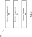
FIG. 5 is a flow diagram of an operating method for an aircraft. -
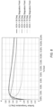
FIG. 6 is a graph plotting chord position versus surface temperature for various different angles of attack. -
FIG. 7 is a top view illustration of the aircraft during aircraft flight. -
FIG. 1 illustrates anaircraft 20 during flight. For ease of description, theaircraft 20 is shown inFIG. 1 and generally described below as an airplane. The methods and systems of the present disclosure, however, are not limited to such an exemplary aircraft. Theaircraft 20, for example, may alternatively be configured as a helicopter, a drone (e.g., an unmanned aerial vehicle (UAV)), a self-propelled projectile or any other manned or unmanned aerial vehicle or system. - The
aircraft 20 extends along alongitudinal axis 22 of theaircraft 20 between a forward, upstreamend 24 of theaircraft 20 to an aft, downstream end 26 (e.g., tail end) of theaircraft 20, whichlongitudinal axis 22 may also be a longitudinal centerline of theaircraft 20 and itsfuselage 28. Theaircraft 20 ofFIG. 1 includes anairframe 30 and one ormore propulsion systems 32; e.g., jet engines, propeller engines, etc. - The
airframe 30 includes thefuselage 28 and a plurality of aircraft airfoils such as a plurality ofwings 34, at least onevertical stabilizer 35, a plurality ofhorizontal stabilizers 36 and the like. Thewings 34 are connected to and disposed on opposing lateral sides of thefuselage 28. Each of thesewings 34 projects laterally out from thefuselage 28, along a span of therespective wing 34, to a tip of therespective wing 34. Thevertical stabilizer 35 is connected to thefuselage 28 and disposed at (e.g., on, adjacent or proximate) the aircraft downstreamend 26. Thisvertical stabilizer 35 projects vertically out from thefuselage 28, along a span of thevertical stabilizer 35, to a tip of thevertical stabilizer 35. Thehorizontal stabilizers 36 are connected to and disposed on opposing lateral sides of thevertical stabilizer 35 at the tip of the vertical stabilizers 35 (or alternatively the fuselage 28). Each of thesehorizontal stabilizers 36 projects laterally out from the vertical stabilizer 35 (or alternatively the fuselage 28), along a span of the respectivehorizontal stabilizer 36, to a tip of the respectivehorizontal stabilizer 36. Each of the aircraft airfoils 34-36 has a leading edge 38-40 which extends along the respective airfoil span. - The
propulsion systems 32 are disposed on opposing lateral sides of thefuselage 28. Each of thesepropulsion systems 32 is connected to thefuselage 28 proximate the aircraft downstreamend 26. However, in other embodiments, eachpropulsion system 32 may be connected to a respective one of thewings 34 or otherwise located with theairframe 30. - Referring to
FIG. 2 , during aircraft flight, theaircraft 20 moves along a flight path 42 through an external environment 44 - the surrounding air. During certain aircraft maneuvers (e.g., aircraft takeoff, aircraft climb, aircraft descent, aircraft landing, etc.), the aircraft flight path 42 may be angularly offset from ahorizon line 46 by a flight path angle 48. The aircraft flight path 42 may also be angularly offset from theaircraft 20 and itslongitudinal axis 22 by an angle ofattack 50. Moreover, theaircraft 20 and itslongitudinal axis 22 may be angularly offset from thehorizon line 46 by apitch attitude 52, where the angle ofattack 50 is equal to thepitch attitude 52 minus the flight path angle 48. Knowing these flight parameters - thepitch attitude 52, the flight path angle 48 and the angle of attack 50 - as well as other flight parameters may be useful for a pilot of theaircraft 20. -
FIG. 3 illustrates aflight information system 54 for determining one or more flight parameters of theaircraft 20. Thisflight information system 54 includes agyroscope 56, one ormore temperature sensors 58 and acontroller 60. - The
temperature sensors 58 are arranged with (e.g., within an interior of) acomponent 62 of theaircraft 20. Thisaircraft component 62 includes anexterior skin 64 and aninternal cavity 66. Theexterior skin 64 is disposed between and fluidly separates theenvironment 44 external to theaircraft 20 from theinternal cavity 66. Theexterior skin 64 ofFIG. 3 , for example, includes anexterior surface 68 and aninterior surface 70. Theskin exterior surface 68 is exposed to theexternal environment 44. Theinterior surface 70 forms a peripheral boundary of theinternal cavity 66 within theaircraft component 62. Examples of theaircraft component 62 include, referring toFIG. 1 , one of thewings 34, one of thehorizontal stabilizers 36, aninlet lip 72 for one of thepropulsion systems 32, anose 74 of thefuselage 28, or any other component of theaircraft 20 with a (e.g., generally horizontal extending) leading edge exposed to theexternal environment 44. - The
temperature sensors 58 ofFIG. 3 are disposed within theinternal cavity 66. Each of thesetemperature sensors 58 is thermally coupled to theexterior skin 64. Thetemperature sensors 58 ofFIG. 3 , for example, are arranged in an array along theexterior skin 64 and itsinterior surface 70. This sensor array extends circumferentially about a leadingedge 76 of theaircraft component 62. More particularly, thetemperature sensors 58 are arranged at a plurality of discrete known measurement locations 78 (e.g., equally) spaced along theinterior surface 70 and about the leadingedge 76; e.g., in a plane perpendicular to aspan 79 of theaircraft component 62. With this arrangement, thetemperature sensors 58 are housed within theaircraft component 62. Thetemperature sensors 58 are thereby shielded from foreign objects within theexternal environment 44 which theaircraft 20 and itsaircraft component 62 may encounter from time to time; e.g., ice, birds, volcanic ash and the like. Examples of thetemperature sensors 58 include, but are not limited to, resistance temperature detectors (RTD), fiber Bragg grating (FBG) devices, thermocouples, and Fabry-Perot sensors. Here, eachtemperature sensor 58 is a discrete device. In other embodiments however, referring toFIG. 4 , the array oftemperature sensors 58 may be incorporated into (or replaced by) a single fiber Bragg grating (FBG) device, or multiple fiber Bragg grating devices. - The
controller 60 ofFIG. 3 is in signal communication (e.g., hardwired and/or wirelessly coupled) with thegyroscope 56 and the one or more temperature sensors 58 (see alsoFIG. 4 ). Thecontroller 60 may be implemented with a combination of hardware and software. The hardware may include amemory 80 and at least oneprocessing device 82, whichprocessing device 82 may include one or more single-core and/or multi-core processors. The hardware may also or alternatively include analog and/or digital circuitry other than that described above. - The
memory 80 is configured to store software (e.g., program instructions) for execution by theprocessing device 82, which software execution may control and/or facilitate performance of one or more operations such as those described below. Thememory 80 may be a non-transitory computer readable medium. For example, thememory 80 may be configured as or include a volatile memory and/or a nonvolatile memory. Examples of a volatile memory may include a random access memory (RAM) such as a dynamic random access memory (DRAM), a static random access memory (SRAM), a synchronous dynamic random access memory (SDRAM), a video random access memory (VRAM), etc. Examples of a nonvolatile memory may include a read only memory (ROM), an electrically erasable programmable read-only memory (EEPROM), a computer hard drive, etc. -
FIG. 5 is a flow diagram of anoperating method 500 for an aircraft. For ease of description, theoperating method 500 is described below with respect to theaircraft 20 ofFIG. 1 and theflight information system 54 ofFIG. 3 (orFIG. 4 ). Theoperating method 500 of the present disclosure, however, is not limited to performance with such elements. - In
step 502, an aircraft parameter is determined. This aircraft parameter is indicative of a position of theaircraft 20 and itslongitudinal axis 22 during the aircraft flight (seeFIG. 2 ). The aircraft parameter, for example, may be thepitch attitude 52 of theaircraft 20. The aircraft parameter may be determined using thegyroscope 56 or any other suitable aircraft instrument. The aircraft parameter may then be provided (e.g., signaled) to thecontroller 60. - In
step 504, a wind parameter is determined. This wind parameter is indicative of a relative wind direction 84 during the aircraft flight (seeFIG. 2 ), where a vector of the relative wind direction 84 is parallel and opposite a vector of the flight path 42. The wind parameter, for example, may be the flight path angle 48 of theaircraft 20; e.g., a relative wind direction angle 86 between the relative wind direction 84 and thehorizon line 46. - The wind parameter may be determined based on a temperature distribution about the leading
edge 76 of theaircraft component 62. A temperature of theexterior skin 64 at each of themeasurement locations 78, for example, may be measured by a respective one of thetemperature sensors 58 to determine the temperature distribution. This temperature distribution is indicative of a changing temperature profile of theexterior skin 64 about its leadingedge 76. Thecontroller 60 may analyze the temperature distribution to identify which one of themeasurement locations 78 is a high temperature location. This high temperature location is themeasurement location 78 associated with a highest measured temperature in the temperature distribution. The high temperature location correlates with a stagnation point along theexterior surface 68 on or near the leadingedge 76. The stagnation point is aligned with a point along theexterior surface 68 where the relative wind direction vector is coincident with and perpendicular to theexterior surface 68. Thecontroller 60 may thereby determine a wind parameter such as the flight path angle 48 of theaircraft 20 / the relative wind direction angle 86 by determining the high temperature location. As shown inFIG. 6 , the stagnation point directly correlates to a wind parameter such as the flight path angle 48 of theaircraft 20 / the relative wind direction angle 86. - For ease of description, the above assumes that a single one of the
measurement locations 78 is associated with the highest measured temperature of theexterior skin 64. However, it is possible twoadjacent measurement locations 78 may both be associated with the highest measured temperature of theexterior skin 64. In such a circumstance, thecontroller 60 may determine an actual location of the highest temperature is between theadjacent measurement locations 78. Alternatively, thecontroller 60 may select one of the two adjacent measurement locations 78 (according to a predetermined method) as being the high temperature location for the purpose of theoperation method 500, particularly where themeasurement locations 78 as close together for example. - In
step 506, an offset angle is determined, where the offset angle may be the angle of attack 50 (seeFIG. 2 ). Thecontroller 60, for example, may process the aircraft parameter and the wind parameter to determine the offset angle. Thecontroller 60 may substrate the flight path angle 48 of the aircraft 20 (or the relative wind direction angle 86) from the flight path angle 48 to determine the offset angle. - While the
operating method 500 is described above with respect to determine the angle ofattack 50, the present disclosure is not limited to determining such an exemplary offset angle. For example, referring toFIG. 7 , theoperating method 500 may also or alternatively determine asideslip angle 88. Thesideslip angle 88 is measured between the aircraft flight path 42 (or the relative wind direction 84) and thelongitudinal axis 22. For such embodiments, theaircraft component 62 ofFIG. 3 may be configured as, referring toFIG. 1 , thevertical stabilizer 35, theinlet lip 72 for one of thepropulsion systems 32, thenose 74 of thefuselage 28, or any other component of theaircraft 20 with a (e.g., generally vertical extending) leading edge exposed to theexternal environment 44. - While various embodiments of the present invention have been disclosed, it will be apparent to those of ordinary skill in the art that many more embodiments and implementations are possible within the scope of the invention. For example, the present invention as described herein includes several aspects and embodiments that include particular features. Although these features may be described individually, it is within the scope of the present invention that some or all of these features may be combined with any one of the aspects and remain within the scope of the invention. Accordingly, the present invention is not to be restricted except in light of the attached claims and their equivalents.
Claims (15)
- A method of operation, comprising:determining an aircraft parameter indicative of a position of a longitudinal axis (22) of an aircraft (20) during a flight of the aircraft (20);determining a wind parameter indicative of a relative wind direction (84) during the flight of the aircraft (20), the wind parameter determined based on a temperature distribution about a leading edge (76) of a component (62) of the aircraft (20); anddetermining an offset angle between the longitudinal axis (22) of the aircraft (20) and the relative wind based on the aircraft parameter and the wind parameter.
- The method of claim 1, wherein the offset angle comprises:an angle of attack (50) of the aircraft (20); and/ora sideslip angle (88) of the aircraft (20).
- The method of claim 1 or 2, wherein:the aircraft parameter comprises a pitch attitude (52) of the aircraft (20) between the longitudinal axis (22) of the aircraft (20) and a horizon line (46); andthe wind parameter comprises a flight path angle (48) between the relative wind direction (84) and the horizon line (46).
- The method of any preceding claim, wherein the aircraft parameter is determined using a gyroscope (56) onboard the aircraft (20).
- The method of any preceding claim, wherein the determining of the wind parameter comprises:measuring a temperature at each of a plurality of measurement locations (78) about the leading edge (76) of the component (62) of the aircraft (20) to determine the temperature distribution;identifying a high temperature location out of the plurality of measurement locations (78) with a highest measured temperature in the temperature distribution; anddetermining the wind parameter based on a position of the high temperature location about the leading edge (76) of the component (62) of the aircraft (20).
- The method of claim 5, wherein:the component (62) of the aircraft (20) comprises a skin (64) and a cavity (66), an interior surface (70) of the skin (64) forms a peripheral boundary of the cavity (66) within the component (62) of the aircraft (20), and an exterior surface of the skin (64) is exposed to an environment external to the aircraft (20); andthe temperature is measured at each of the plurality of measurement locations (78) using one or more temperature sensors (58) connected to the skin (64) at the interior surface (70) and/or disposed within the cavity (66) and thermally coupled to the skin (64).
- The method of claim 5, wherein the temperature is measured at each of the plurality of measurement locations (78) using one or more temperature sensors (58) disposed within the component (62) of the aircraft (20).
- The method of any preceding claim, wherein the component (62) comprises an aircraft airfoil (34-36).
- A method of operation, comprising:measuring a temperature at a plurality of measurement locations (78) about a leading edge (76) of a component (62) of an aircraft (20) to determine a temperature distribution, the temperature measured at the plurality of measurement locations (78) using one or more temperature sensors (58) disposed within the component (62) of the aircraft (20);identifying a high temperature location out of the plurality of measurement locations (78) with a highest measured temperature in the temperature distribution; anddetermining a parameter for the aircraft (20) based on a position of the high temperature location about the leading edge (76) of the component (62) of the aircraft (20).
- The method of claim 9, wherein the parameter is indicative of:a relative wind direction (84) during the flight of the aircraft (20); and/ora stagnation point about the leading edge (76) of the component (62) of the aircraft (20).
- The method of claim 9 or 10, further comprising determining:an angle of attack (50) of the aircraft (20) based on the parameter; and/ora sideslip angle (88) of the aircraft (20) based on the parameter.
- A method of operation, comprising:determining an aircraft parameter indicative of a position of a longitudinal axis (22) of an aircraft (20) during a flight of the aircraft (20);determining a wind parameter indicative of a relative wind direction (84) during the flight of the aircraft (20), the wind parameter determined based on a position of a stagnation point about a leading edge (76) of a component (62) of the aircraft (20); anddetermining an offset angle between the longitudinal axis (22) of the aircraft (20) and the relative wind based on the aircraft parameter and the wind parameter.
- The method of claim 12, wherein the determining of the wind parameter comprises:measuring a temperature at a plurality of measurement locations (78) about the leading edge (76) of the component (62) of the aircraft (20) to determine a temperature distribution about the leading edge (76) of the component (62) of the aircraft (20);identifying a high temperature location out of the plurality of measurement locations (78) with a highest measured temperature in the temperature distribution; anddetermining the position of the stagnation point based on a position of the high temperature location about the leading edge (76) of the component (62) of the aircraft (20).
- The method of claim 12 or 13, wherein:the wind parameter is determined using one or more sensors disposed within an interior (74) of the component (62) of the aircraft (20); and/orthe component (62) comprises an aircraft wing (34).
- The method of any of claims 12 to 14, wherein:the aircraft parameter is determined using a gyroscope (56) onboard the aircraft (20); andthe offset angle comprises an angle of attack (50) or a sideslip angle (88) of the aircraft (20).
Applications Claiming Priority (1)
| Application Number | Priority Date | Filing Date | Title |
|---|---|---|---|
| US18/372,503 US20250100707A1 (en) | 2023-09-25 | 2023-09-25 | Determining a flight parameter based on a leading edge temperature distribution |
Publications (1)
| Publication Number | Publication Date |
|---|---|
| EP4528289A1 true EP4528289A1 (en) | 2025-03-26 |
Family
ID=92900146
Family Applications (1)
| Application Number | Title | Priority Date | Filing Date |
|---|---|---|---|
| EP24202347.1A Pending EP4528289A1 (en) | 2023-09-25 | 2024-09-24 | Determining a flight parameter based on a leading edge temperature distribution |
Country Status (2)
| Country | Link |
|---|---|
| US (1) | US20250100707A1 (en) |
| EP (1) | EP4528289A1 (en) |
Citations (3)
| Publication number | Priority date | Publication date | Assignee | Title |
|---|---|---|---|---|
| US4968879A (en) * | 1988-07-29 | 1990-11-06 | The Boeing Company | Method and apparatus for measuring aircraft flight parameters |
| US9702892B1 (en) * | 2014-11-21 | 2017-07-11 | Lockheed Martin Corporation | Thermal air data (TAD) system |
| US20190217966A1 (en) * | 2018-01-12 | 2019-07-18 | Rosemount Aerospace Inc. | Aircraft air data generation using laser sensor data and inertial sensor data |
Family Cites Families (4)
| Publication number | Priority date | Publication date | Assignee | Title |
|---|---|---|---|---|
| US6772976B1 (en) * | 2002-04-10 | 2004-08-10 | Honeywell International, Inc. | Sensor for measuring wind angle |
| GB201108855D0 (en) * | 2011-05-26 | 2011-07-06 | Bae Systems Plc | Aircraft wing and sensor |
| CN106679932B (en) * | 2017-01-23 | 2019-02-12 | 厦门大学 | Angle of attack measurement method based on miniature flexible thermal film sensor array |
| EP3457146A1 (en) * | 2017-09-13 | 2019-03-20 | Siemens Gamesa Renewable Energy A/S | Determining air flow characteristic |
-
2023
- 2023-09-25 US US18/372,503 patent/US20250100707A1/en active Pending
-
2024
- 2024-09-24 EP EP24202347.1A patent/EP4528289A1/en active Pending
Patent Citations (3)
| Publication number | Priority date | Publication date | Assignee | Title |
|---|---|---|---|---|
| US4968879A (en) * | 1988-07-29 | 1990-11-06 | The Boeing Company | Method and apparatus for measuring aircraft flight parameters |
| US9702892B1 (en) * | 2014-11-21 | 2017-07-11 | Lockheed Martin Corporation | Thermal air data (TAD) system |
| US20190217966A1 (en) * | 2018-01-12 | 2019-07-18 | Rosemount Aerospace Inc. | Aircraft air data generation using laser sensor data and inertial sensor data |
Also Published As
| Publication number | Publication date |
|---|---|
| US20250100707A1 (en) | 2025-03-27 |
Similar Documents
| Publication | Publication Date | Title |
|---|---|---|
| EP2317293B1 (en) | Total air temperature probe and method for reducing de-icing/anti-icing heater error | |
| US20120298801A1 (en) | Aircraft wing and sensor | |
| US20090018703A1 (en) | System and Method for Control of Aeroelasticity Effects | |
| Hansen et al. | The NASA dryden AAR project: a flight test approach to an aerial refueling system | |
| ES2919573T3 (en) | Procedure and assistance system for the detection of flight performance degradation | |
| US20090055036A1 (en) | System for acquiring air data during flight | |
| US20150360794A1 (en) | Rotorcraft having an airspeed sensor located at the top of a tail fin of the rotorcraft | |
| US11162812B2 (en) | Optimal path planning with optical air velocity sensing | |
| US10071808B1 (en) | Aircraft icing conditions detection systems and methods | |
| EP3480121A1 (en) | Spacecraft and landing method therefor | |
| EP3578457B1 (en) | Method and apparatus for reducing aircraft wing bending moment | |
| US20040024500A1 (en) | Method for estimating wind | |
| US10977880B2 (en) | Hover time remaining for an aircraft | |
| Nicolosi et al. | Stability, flying qualities and longitudinal parameter estimation of a twin-engine CS-23 certified light aircraft | |
| US20190112056A1 (en) | Helicopter rotor icing detection system and method | |
| EP3450989A2 (en) | Aerometric method and device (system) for measuring aircraft spatial position, yaw and lateral velocity | |
| EP0629166A1 (en) | Aerodynamic pressure sensor systems | |
| US20250100707A1 (en) | Determining a flight parameter based on a leading edge temperature distribution | |
| EP2955106B1 (en) | Rotorcraft flight parameter estimation | |
| Blake et al. | UAV aerial refueling-wind tunnel results and comparison with analytical predictions | |
| GB2491167A (en) | Aircraft wing blister | |
| US11292589B2 (en) | Method of automatically adjusting lift provided for a hybrid rotorcraft, and an associated hybrid rotorcraft | |
| Siu et al. | Flight test results of an angle of attack and angle of sideslip calibration method using Output-Error optimization | |
| CN121657731B (en) | Unmanned aerial vehicle wind-resistant attitude regulation and control method and device based on porous pneumatic probe | |
| Raab et al. | Support of icing flight tests by near real-time data analysis |
Legal Events
| Date | Code | Title | Description |
|---|---|---|---|
| PUAI | Public reference made under article 153(3) epc to a published international application that has entered the european phase |
Free format text: ORIGINAL CODE: 0009012 |
|
| STAA | Information on the status of an ep patent application or granted ep patent |
Free format text: STATUS: THE APPLICATION HAS BEEN PUBLISHED |
|
| AK | Designated contracting states |
Kind code of ref document: A1 Designated state(s): AL AT BE BG CH CY CZ DE DK EE ES FI FR GB GR HR HU IE IS IT LI LT LU LV MC ME MK MT NL NO PL PT RO RS SE SI SK SM TR |
|
| STAA | Information on the status of an ep patent application or granted ep patent |
Free format text: STATUS: REQUEST FOR EXAMINATION WAS MADE |
|
| 17P | Request for examination filed |
Effective date: 20250926 |