EP4528271A1 - Dissolution testing apparatus with a common heating channel - Google Patents
Dissolution testing apparatus with a common heating channel Download PDFInfo
- Publication number
- EP4528271A1 EP4528271A1 EP23198981.5A EP23198981A EP4528271A1 EP 4528271 A1 EP4528271 A1 EP 4528271A1 EP 23198981 A EP23198981 A EP 23198981A EP 4528271 A1 EP4528271 A1 EP 4528271A1
- Authority
- EP
- European Patent Office
- Prior art keywords
- dissolution
- heating
- cells
- medium
- heating channel
- Prior art date
- Legal status (The legal status is an assumption and is not a legal conclusion. Google has not performed a legal analysis and makes no representation as to the accuracy of the status listed.)
- Granted
Links
Images




Classifications
-
- G—PHYSICS
- G01—MEASURING; TESTING
- G01N—INVESTIGATING OR ANALYSING MATERIALS BY DETERMINING THEIR CHEMICAL OR PHYSICAL PROPERTIES
- G01N33/00—Investigating or analysing materials by specific methods not covered by groups G01N1/00 - G01N31/00
- G01N33/15—Medicinal preparations ; Physical properties thereof, e.g. dissolubility
Definitions
- the invention relates to a dissolution testing apparatus used for drug release testing and dissolution testing, comprising a heating arrangement for tempering one or more testing cells, particularly one or more flow-through cells of a flow-through cell instrument or apparatus.
- Dissolution testing is a compendial in vitro test for example used in pharmaceutical research and development to characterize the release rate of an Active Pharmaceutical Ingredient (API) from a formulated dosage form, under reproducible conditions, in correlation with its in vivo performance.
- API Active Pharmaceutical Ingredient
- compositions include granules, tablets, capsules, gels, creams, ointments, suspensions, suppositories, patches, microspheres, implants and other long acting injectables as micro and nano suspensions and others.
- “Dissolution testing” is a term used for solid dosage forms and the more general term: “Drug release testing” is used for other dosage forms, including coated medical devices.
- dissolution testing apparatuses are also used in applications such as nicotine release from smokeless tobacco products and for persistence tests of stone wool fibers in lung fluids.
- the first interest of a dissolution testing apparatus in form of a flow-through cell dissolution instrument lies in its flexibility as the cell and its inside arrangement can be adapted to the tested formulation structure and challenges.
- Dissolution testing modalities for solid dosage forms and apparatus involved are described in a general dissolution chapter harmonized between European, US and Japanese Pharmacopeias: the USP ⁇ 711>.
- the flow-through cell dissolution is also described as method 6 in the Chinese Pharmacopeia.
- Standardized methods use for example a paddle apparatus for stirring substances in a container as for example described in EP 0746759 A1 , a basket apparatus for holding the substance in a basket as for example described in US 5816701 A , or a flow-through apparatus providing dissolution medium flowing through a cell containing the substance as for example described in WO 2013/003518 A1 .
- the dimensions and tolerances of such apparatuses are specified precisely.
- Critical test parameters that have to be monitored periodically during use include for example volume and temperature of the dissolution medium, rotation speed and flow rate of medium.
- the flow-through apparatus is used for a wide range of objects to be tested.
- the flow-through cell dissolution principle consists in flowing dissolution medium at defined temperature and flow rate onto a cell containing the dosage form to be tested.
- the total volume of dissolution medium is based on the solubility of the active pharmaceutical ingredient respectively substance, to be dissolved and the test duration is ideally correlated to the In vivo performance of the tested product. Therefore, the temperature of the media (from 32°C for transdermal products to 37°C for oral products and up to higher temperatures in the scope of accelerated testing) flowing into the cell has to be controlled all through the test.
- the cell temperature control and its efficiency are linked to two processes: the temperature control of the media flowing into the cell (at different possible flow rates as the flow rate is a method parameter) and the ambient temperature of the chamber the cell stays in.
- the flow-through apparatus can be realized as an open system or a closed system as for example illustrated in EP 0049293 A1 .
- the open system uses dissolution medium that is pumped, in all channels, from a reservoir through the cells and collected or analysed after the cells.
- the open system is for example recommended for poorly soluble drugs which require a high volume of media or for pH changes to be performed for example in order to mimic the Gastro-Intestinal tract.
- the media is pumped from one single reservoir per channel, through the cell and brought back to the reservoir. These individual loops for each channel allow an accumulation of dissolved active ingredient in the reservoirs which can be sampled or analysed.
- a dissolution testing apparatus is composed of multiple channels to allow at least the simultaneous testing of seven channels (six samples and a reference). Therefore, the seven channels have to be qualified in a documented procedure (Installation Qualification, Operational Qualification) prior to any use of the apparatus to prove that they allow an equivalent testing on all channels, as finally samples will be compared to specifications as they are representing the entire manufactured batch.
- the temperature in each cell (as the flow rate of media entering) has therefore to be accurate and consistent all over the test duration in order that the test only detects sample variations.
- the heating systems which guarantee the right cell temperature are individual water jackets adopted in water by a temperature-controlled water bath.
- the same source of heat is used for the temperature regulation of entering media and cells.
- the cells are for example provided with heating systems comprising individual heating elements or heating units for each cell, as for example shown in WO 2010/059643 .
- an air stream or an air bath may be applied to each cell for tempering the cell and the dissolution medium, respectively, as for example shown in US 2015/0358587 A1 .
- the cells can be associated to temperature sensing elements, which are connected to heat control systems for controlling the temperature in the cell.
- the known dissolution testing apparatuses oftentimes are slow or complicated in adjusting the temperature of the dissolution medium in the cells. Particularly, heating arrangements using a water bath are difficult to control in a short period of time. Further, heating elements applied to each individual vessel as disclosed in the state of the art require additional application and maintenance steps for preparing and performing the testing. Most apparatuses are designed as an open system or a closed system, and they are not set up to easily switch between an open and closed configuration. Such shortcomings impact efficient quality control, compliance monitoring and product optimization.
- a dissolution testing apparatus for dissolving a dissoluble substance in a dissolution medium comprises at least one reservoir for the dissolution medium, several dissolution cells each designed for holding a dissoluble substance to be tested and a pump device for adding dissolution medium to the cells.
- the several cells are arranged in a common heating channel.
- a heater is connected to the heating channel for heating a gaseous heating medium, for example air, in the heating channel.
- a gaseous heating medium for example air
- a ventilator is arranged in the heating channel for creating a heated air or gas stream along the cells.
- the ventilator can be arranged in front of or behind the heater to blow heated air towards and along the cells in the heating channel.
- the heated stream created by the ventilator ensures uniform distribution of thermal energy within the common heating channel along the cells.
- the dissolution cells are aligned along a longitudinal axis of the heating channel in the flow direction of the heated medium stream. This arrangement supports efficient interaction with the tempering stream and allows a compact design.
- the heating channel is realized as a heating channel loop comprising a first elongated section accommodating the several cells and a second elongated section accommodating the heater and the ventilator.
- the several cells can be aligned along a longitudinal axis of the first elongated section of the heating channel.
- the heater and the ventilator can be aligned along a longitudinal axis of the second elongated section of the heating channel.
- the heating channel loop provides an enclosed space for the gaseous heating medium to be heated.
- the ventilator provides circulation of the heating medium within the heating channel.
- the loop design reduces the energy required to heat the heating channel to a desired temperature level and facilitates retaining the temperature level.
- the heating channel comprises an opening along the length of the elongated section housing the dissolution cells and a cover for closing the opening for providing access to the several cells.
- the opening is used for inserting and removing dissolution cells
- the heater comprises a plurality of flat heating elements, like heating plates or heating grids, arranged in the heating channel along a longitudinal axis of the heating channel.
- the flat surface of the heating elements runs along the length of the heating channel. This avoids disturbances of the heating stream and allows an extended time of contact between the heating medium and the heating elements, which results in efficient heating of the heating medium.
- guiding plates are located in the heating channel upstream of the several cells for supporting a laminar flow along the cells.
- guiding plates are arranged in curved section and/or in front of the cell section of the heating channel.
- the guiding plates are arranged in parallel or concentrically with respect to a radius of the curved section.
- a set of guiding plates is equally distanced along the width of the heating channel. For example, 3 to 8 guiding plates, depending on the size of the channel, are spread across the heating channel.
- the heating channel comprises fluid passages for dissolution medium conduits in fluid connection with cell inlets for providing dissolution medium into the cells.
- the dissolution cells can be placed in the heating channel and dissolution medium can be added to the cells as needed.
- a dissolution medium heating module is provided as a flow-through module in-line with a dissolution medium reservoir outside the heating channel and the dissolution cells inside the heating channel.
- the dissolution medium heating module pre-heats the dissolution medium before administering the medium into the dissolution cells.
- the dissolution medium can be heated to a desired temperature outside the dissolution cell and the heating channel. Once the heated dissolution medium is transferred into the dissolution cells in the heating channel, the heated gaseous medium stream keeps the dissolution medium at the pre-heated temperature and allows for quick adjustments of the temperature if needed.
- the dissolution medium heating module comprises a heating chamber, which is connect or connectable to the dissolution medium reservoir, for example through a pump device, for receiving the dissolution medium. At least one planar heating surface is arranged at the heating chamber for heating the dissolution medium therein.
- the heating chamber is advantageously realized as a two-dimensional heating loop structure comprising a medium inlet at one end of the heating loop structure and a medium outlet at an opposite end of the heating loop structure for receiving and dispensing dissolution medium.
- the at least one planar heating surface is provided adjacent to the heating loop structure for emitting and transferring thermal energy to the heating loop structure.
- the dissolution medium heating module allows for fast and precise heating of the dissolution medium while it continuously flows into the dissolution cells in the heating channel.
- the dissolution testing apparatus is designed for a closed loop configuration and/or an open loop configuration, like known for a USP 4 apparatus, wherein the dissolution cells are a flow-through cells comprising a cell inlet for the dissolution medium and a cell outlet for a sample solution containing dissolution medium and dissolved substance.
- the sample solution can be returned as dissolution medium into the flow-through cell to accumulate dissolved active in the reservoir.
- the sample solution is extracted in fractions and then transferred into vials for analytical testing or analysed on-line.
- the heating channel comprises fluid passages for dissolution medium conduits in fluid connection to an in-flow conduit into the cell and an out-flow conduit out of the cell.
- a lower and an upper wall of the heating channel located below and above the flow-through cells comprise connection ports for establishing a fluid communication to the in-flow conduit and the out-flow conduit.
- the fluid passages of the channel may connect to a dissolution medium reservoir, or the dissolution medium heating module as mentioned above, and to a sample solution conduit transferring sample solution for extraction or testing.
- the flow-through cells are preferably arranged such, that a flow of dissolution medium through the cells is perpendicular to a heated medium stream in the heating channel. This simplifies the positioning of the heating channel in the dissolution testing apparatus and the positioning of the flow-through cells within the channel.
- the heating channel is also suitable for heating a dissolution medium used in other cell configurations of a dissolution testing apparatus, like filled vessels instead of flow-through cells.
- At least one temperature sensor is provided in the heating channel and/or at one or more of the dissolution cells.
- a temperature sensor can be positioned at the beginning of the elongated section housing the dissolution cells and/or at the end of that section.
- the temperature sensors may provide instant temperature monitoring of the temperature conditions in the heating channel and directly at the dissolution cells, which allows for precise dissolution testing.
- the dissolution testing apparatus comprises a control unit connected to at least one temperature sensor for controlling the heater and/or the ventilator for example according to temperature measurements of the temperature sensors.
- the control unit may control the dissolution medium heating module for adjusting an input temperature of the dissolution medium into the dissolution cells.
- the control unit also controls the flow rate of the dissolution medium to ensure constant and continuous medium input to the dissolution cell.
- the dissolution testing apparatus improves the reproducibility of the assessment of dissolution qualities of dissoluble substance by assuring compliance to test requirements.
- the dissolution testing apparatus assists in providing consistent dissolution quality for dissolving substances, particularly of drug substances. Also, it provides a predictive measure of the efficacy of API substances and other drug-based applications due to accurate temperature setting of the dissolution medium.
- FIG 1 illustrates a setup of a dissolution testing apparatus as used in the present invention.
- the dissolution testing apparatus comprises a dissolution module 1, an extraction module 2 and a sample module 3.
- the dissolution testing apparatus can be operated in a closed mode configuration, or an open mode configuration as will be explained below.
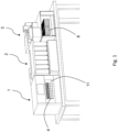
- the dissolution module 1 accommodates several dissolution cells designed as flow-through cells 4, that are lined up in a cell chamber 11 of the dissolution module 1. Each cell is filled with a dissoluble substance 5 (see Figure 7a and 7b ).
- the flow-through cells 4 are supplied with dissolution medium by dissolution medium heating modules 6 arranged below the cells in the dissolution module 1, as depicted in Figure 2 .
- the dissolution medium including dissolved substance exits the flow-through cells 4 as a sample solution containing dissolution medium and dissolved substance.
- the sample solution is transferred to the extraction module 2 via a sample solution conduit 7.
- defined fractions of the sample solution are extracted from the sample solution conduit 7 into sample vials 8.
- the sample fractions in the sample vials can be tested and returned to their respective cell or the sample vials can be transferred to the sample module 3 for testing.
- the heating chamber 11 is realized above the dissolution medium heating modules 6 for heating the dissolution medium before the dissolution medium enters the cells 4.
- An assembly structure 90 in form of a mounting plate is arranged inside the dissolution module 1.
- the assembly structure 90 comprises a cell rack holder 91 for holding the flow-through cells 4 upright and aligned along a longitudinal axis, a connector bar 92 comprising connector ports for connecting cell outlets 13 to the sample solution conduits 7, and a connector platform 93 for supporting the dissolution medium heating modules 6 below the platform and the flow-through cells 4 on top of the platform.
- the connector platform 93 comprises connector ports for connecting medium outlet lines 28 of the heating modules 6 to cell inlets 12 (see Figure 3 ).
- the connector bar 92 and the connector platform 93 extend distanced from each other and basically perpendicular from the assembly structure 90. Thus, the assembly structure 90, the connector bar 92 and the connector platform 93 create the cell chamber 11.
- FIG. 2 seven flow-through cells 4 are positioned in the cell chamber 11 such that a cell volume 10 (see Figure 7b ) is fully exposed and accessible from all sides through walls of the flow-through cells, for example for visual inspection and interaction with conditions of the ambient environment present in the cell chamber 11.
- the cells comprise the cell inlet 12 at a bottom end and the cell outlet 13 at an upper end.
- the cell outlets 13 are in fluid communication with sample solution conduits 7, which deliver the sample solution to the extraction module 2.
- the bottom end of the flow-through cells 4 is positioned on the connector platform 93 for fluid connection to the dissolution medium heating modules 6 arranged below the connector platform 93 in the dissolution module 1.
- Each flow-through cell 4 is associated to one dissolution medium heating module 6, respectively, wherein the dissolution medium heating modules 6 are aligned next to each other below the cells.
- the several cells are arranged commonly in the heating channel 100 and a heater 101 is connected to the heating channel 100 for heating a gaseous heating medium in the heating channel, as will be described in more detail in Figure 5 .
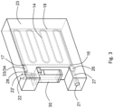
- FIGS 3 and 4 show the dissolution medium heating module 6 according to the present invention.
- the heating module comprises a heating chamber, which is realized as a two-dimensional heating loop structure 14.
- the heating loop structure 14 is for example designed as a medium conduit that loops in one plane for example in a serpentine pattern.
- the heating loop structure 14 is connected to a dissolution medium reservoir 15 (see Figures 8a and 8b ) via a pump device 60 for receiving a dissolution medium.
- the heating loop structure 14 comprises a medium inlet 16 at one end of the heating loop structure 14 and a medium outlet 17 at an opposite end of the heating loop structure 14 for receiving and dispensing dissolution medium.
- a planar heating surface in form of a heating plate 18 is arranged adjacent to the heating loop structure 14 for heating the dissolution medium in the heating loop structure 14.
- the heating plate 18 comprises a size that covers an area of the two-dimensional heating loop structure.
- two or more heating plates or other flat heating elements or plates could be used to cover the heating loop area.
- the heating plate 18 is for example a ceramic plate that comprises interior heating coils.
- silica materials or metal could be used for the planar heating surface.
- the heating module receives dissolution medium from the external dissolution medium reservoir 15, which is for example located in the dissolution module 1 or in the extraction module 2 of the dissolution testing apparatus.
- the dissolution medium heating module 6 comprises two housing half shells, which enclose the heating loop structure 14 and the heating plate 18 in an assembled state.
- One or both of the housing half shells can comprise a recess structure that corresponds to the two-dimensional heating loop structure 14 for providing, respectively receiving, the heating loop structure therein.
- the housing half shells have an inlet through hole 21 as well as a first and second outlet through hole 22 and 22' serving as medium conduits to and from the medium inlet 16 and the medium outlet 17 of the heating loop structure 14.
- the two housing half shells can be screwed together to realise a heating block 23 of the heating module 6.
- the dissolution medium heating module 6 comprises a pressure sensor 26 in a medium inlet line 27 for monitoring a pressure in the heating loop structure 14.
- the medium inlet line 27 is provided by the through passage of the through hole 21 and is detachably connected to the external dissolution medium reservoir 15 for example by an input port at the through hole 21.
- the medium outlet 17 merges into a medium outlet line 28, which enters a valve unit 30 (see Figures 6a - 6c ), which can be attached to the housing.
- the valve unit 30 switches between parallel through passages provided by the first through hole 22 and the second through hole 22'.
- the first through hole 22 is connectable to the cell inlet 12 to provide tempered dissolution medium to a flow through cell 4.
- the second through hole 22' is connectable to a bypass conduit 31 for bypassing the cell.
- Each of the through holes 22 and 22' comprise a temperature sensor 33 and 34, respectively, for monitoring the temperature of the dissolution medium exiting the heating loop structure 14.
- the temperature sensors 33/34 and the pressure sensor 26 can be placed in the medium inlet line 27 and the through holes 22/22' when the two housing half shells are assembled to realise the heating block 23.
- the heating module comprises a slim design, wherein a thickness measured across the two half shells is only approximately half of a length or a hight of the heating module. Preferably, the thickness is only about a 1/3, more preferably only about 1/4, of the length or height.
- the slim design allows to provide individual dissolution medium heating modules 6 for each of the flow-through cells 4 of the dissolution testing apparatus without occupying a large space.
- a media selector 80 may be connected to the medium inlet line 27 for selectively adding a solvent to the dissolution medium before the medium enters the heating loop structure, as mentioned above.
- the medium can be provided to the inlet line 27 by a pump device 60.
- the dissolution medium heating modules 6 are detachably mounted in the dissolution module 1 and the medium outlet line 28 of the heating loop structure 14 is detachably connected to the cell inlet 12.
- the heating module 6 can be replaced easily for maintenance.
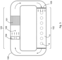
- FIG. 5 shows a heating arrangement for heating the several dissolution cells 4 accommodated in the cell chamber 11 of the dissolution module 1.
- the cell chamber 11 is part of the heating channel 100 common for all cells 4.
- the heater 101 is arranged in the heating channel 100 for heating a gaseous medium, like air or another gas, in the heating channel 100.
- a ventilator 104 is arranged next to the heater 101 in the heating channel 100 for creating a heated medium stream in the heating channel and along the flow-through cells 4.
- the heating channel 100 is realized as a heating channel loop comprising a first elongated section 102 accommodating the cell chamber 11 with the several flow-through cells 4 and a second elongated section 103 accommodating the heater 101 and the ventilator 104.
- the first elongated section 102 and the second elongated section 103 are connected by curved sections to realize the heating channel loop.
- the several flow-through cells 4 are aligned along a longitudinal axis of the first elongated section 102.
- the heater 101 comprises a plurality of flat heating elements, like heating plates, arranged in the heating channel 100 along a longitudinal axis of the heating channel.
- the air stream also flows along the longitudinal axis and can easily pass by the flat heating elements to be heated.
- a set of guiding plates 105 is located upstream of the several cells 4 for supporting a laminar flow along the cells in the first elongated section 102 of the heating channel 100. Further guiding plates may be located in curved section of the heating channel for supporting a laminar flow along the heater 101 and the ventilator 104.
- the heating channel 100 comprises fluid passages (not shown in Figure 5 ) for dissolution medium conduits in fluid connection with the flow-through cells 4, for example for the medium outlet line 28 of the heating module 6 or the in-flow conduit 40 that is connected to the cell inlet 12 for transmitting dissolution medium into the cell 4 and for the out-flow conduit 41 or the sample solution conduit 7 for transmitting sample solution from the cell outlet 13 to the extraction module 2.
- the heating chamber 11 of the heating channel 100 is realized above the dissolution medium heating modules 6 for heating the dissolution medium before it enters the cells 4.
- the assembly structure 90, the connector bar 92, the connector platform 93 and a housing side of the dissolution module 1 create the cell chamber 11 and the heating channel 100, respectively.
- the heater and the ventilator may be located on a back side of the assembly structure 90.
- the dissolution module housing comprises the opening along the length of the sample chamber 11 and the cover (not shown) for closing the opening.
- the opening and the cover provide access to the cell chamber 11 for positioning the flow-through cells therein and connecting them to the connection ports.
- the cells are surrounded by the heated medium stream and the flow of the dissolution medium through the cells is perpendicular to the heat stream in the heating channel 100, which allows for uniform exposure to the heated air.
- the dissolution medium is quickly and effectively heated to a desired temperature by the heating modules 6, while the dissolution medium is in flow to the flow-through cells 4.
- the heating loop structures 14 of the heating modules 6 are arranged in-line of the dissolution medium flow between the dissolution medium reservoir 15 and the flow-through cells 4, wherein the medium flow is generated by the pump device. That means the heating modules 6 are arranged in series with their associated cells 4.
- the dissolution medium is kept at the temperature achieved by the heating modules 6 while the medium flows through the cells 4 by the heated medium stream in the heating channel 100. This set up ensures a precise continuous flow of medium through the cells with a predetermined constant temperature and enables flexible and predictive dissolution testing of dissoluble substances.
- the dissolution testing apparatus does not depend on the heating modules 6.
- the dissolution medium can easily be heated by the heated medium stream in the heating channel 100 as provided by the present invention once the dissolution medium has entered the dissolution cells. The several cells are exposed commonly to the heated stream and the dissolution medium therein is heated uniformly for all cells.
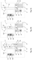
- Figures 6a to 6c describe different operations of the dissolution testing apparatus according to the present invention, schematically illustrating a flow of the dissolution medium through the dissolution medium heating module 6 and the heating channel 100.
- the common heating channel comprises at least one temperature sensor 106 in the first elongated section 102 of the heating channel 100, which houses the several flow-through cells 4. Further temperature sensors can for example be located at or near at least one of the flow-through cells 4 and in the area of the heating channel accommodating the ventilator 104.
- a control unit at the heating channel and/or a controller of the dissolution testing apparatus may receive information data of the temperature sensors for controlling the heater 101 and/or the ventilator 104 according to a desired temperature in the heating chamber 11.
- the dissolution medium heating module 6 may comprise control sensors for monitoring and controlling the operation of the heating module 6 and the dissolution testing apparatus.
- at least one temperature sensor may be provided for monitoring a temperature of the dissolution medium while it is flowing through the heating module.
- a temperature sensor may for example be provided at the medium inlet line 27.
- a temperature sensor 33 may for example be provided at the medium outlet line 28.
- at least one pressure gauge 35 or pressure sensor may be arranged for example in the medium inlet line 27 and/or the medium outlet line 28, which could provide pressure measurements for controlling the pump 60.
- a control unit 29 controls the at least one heating plate 18 of the heating module 6 and the pump operation, as will be explained below.
- dissolution medium is provided by the medium inlet line 27 and enters the heating loop structure 14, wherein it is heated by the heating plate 18 while flowing through the structure.
- the temperature sensor 33 measures a temperature and the pressure gauge 35 measures a pressure of the dissolution medium in the medium outlet line 28.
- the bypass valve 30 arranged in the medium outlet line 28 dispenses the dissolution medium ether to an in-flow conduit 40 connected with the cell inlet 12 or to the bypass conduit 31.
- a temperature sensor 34 measures a temperature in the bypass conduit 31.
- the dissolution medium is already heated by the heating module 6, flows through the flow-through cell 4 and dissolves the dissoluble substance 5 therein, which results in a sample solution containing dissolution medium and a portion of the substance dissolved therein.
- the sample solution exits the flow-through cell 4 through the cell outlet 13 into an out-flow conduit 41.
- the out-flow conduit 41 and the bypass conduit 31 end in the bypass valve 32, from where medium flow continues into the sample solution conduit 7 towards the extraction module 2 and/or sample module 3.
- the dissolution testing apparatus is operated in a testing mode, wherein heated dissolution medium is transferred from the dissolution medium heating module 6 into the flow-through cell 4 in the heating channel 100.
- the temperature in the flow-through cell 4 is kept or adjusted in the heating channel, while dissoluble substance dissolves into the dissolution medium.
- a sample solution is emitted into the sample solution conduit 7.
- the sample solution can be tested while flowing through the sample solution conduit 7, for example using optical analysis testing, or is directed to the extraction module 2 for extraction into sample vessels 8 and testing.
- the dissolution testing apparatus is operated in a bypass mode, wherein the split valve 30 directs dissolution medium from the medium outline line 28 and the through hole 22' of the heating module 6 into the bypass conduit 31. This may be the case for example, if the flow-through cell is clogged, or in case of any other failure of the dissolution testing apparatus. From the bypass conduit 31 the bypass valve 32 directs the dissolution medium into the sample solution conduit 7, from where the dissolution medium may be discarded or returned into the dissolution medium cycle.
- the dissolution testing apparatus is operated in a cleaning mode, wherein the flow-through cell has been removed from the cell chamber 11.
- the dissolution medium or a cleaning medium may be used for cleaning the conduits of the dissolution testing apparatus.
- the medium runs through the heating module 6 and the bypass valve 30 directs the medium through the bypass conduit 31 and a replacement conduit 42 replacing the in-flow conduit 40, the flow-through cell 4 and the out-flow conduit 41.
- the bypass valve 32 directs the medium into the sample solution conduit 7.
- FIGS 7a and 7b show a flow-through cell 4 as it can be used for the present invention in an assembled top view and a schematical interior view.
- the flow-through cell 4 comprises a cell volume 10 having a generally cylindrical shape and a predefined size.
- the cell volume 10 is tapered towards the bottom end, which comprises the cell inlet 12, and is open at an upper end.
- a dissoluble substance 5 is placed in the cell volume 10.
- Holding structures like a basket, a bead bed or similar may be used inside the cell volume to place the dissoluble substance distanced from the bottom if required by a used testing method or a shape of a dissoluble substance.
- a closing ring 50 with a central through passage and a holding frame for a filter 51 is placed on the upper opening of the cell volume 10.
- the filter 51 can be selected according testing requirements for the tested dissoluble substance.
- a cap 52 comprising the cell outlet 13 is mounted on the closing ring 50 to close the cell volume 10 and keep the filter 51 in place.
- the closing ring 50 and the cap 52 can be realized a single piece, wherein the filter 51 can be arranged in the single piece before mounting the piece on the cell volume.
- the cell volume 10 is made for example of glass or plastic material that is inert with respect to the dissoluble substance and comprises transparent walls for observing the dissolution process.
- the cell volume 10 does not need to be placed in additional containers as known from the prior art for providing heating means at the cell.
- the flow-through cell 4 comprises a simple design and allows for easy preparation of dissoluble substances for testing.
- the closing ring 50 or the cap 52 may comprise an electronic chip, a temperature sensor, a positioning sensor, a flow meter, and other sensor means.
- the electronic chip is designed for wireless communication with the controller of the dissolution testing apparatus and transmits information data of the temperature at the dissolution volume, the cell position, the flow through the cell, etc..
- the data can be used for controlling the dissolution medium heating modules 6, the heater 101 in the heating channel 100, the pumps of the apparatus, and other functions of the dissolution testing apparatus as well as for recording the testing conditions.
- Figures 8a and 8b illustrate a testing method provided by the dissolution testing apparatus of the present invention in an open loop configuration and a closed loop configuration using a flow-through cell 4.
- fresh dissolution medium is supplied by one or more medium reservoirs 15 provided by a media selector and pumped towards the flow-through cell 4 by a medium pump 60.
- the dissolution medium flows through the heating module 6, where it is heated to a pre-selected temperature, and into the flow-through cell 4 in the heating channel 100.
- the dissolution medium flows through the flow-through cell 4 and crosses the dissoluble substance 5 to create a sample solution.
- the sample solution flows from the flow-through cell to the bypass valve 32, which directs the sample solution to the extraction module 2 or to a waste conduit 61.
- fractions of the sample solution are extracted into sample vials 8 for testing.
- the total amount of dissolution medium is determined by the flow rate created by the medium pump.
- the total media volume is infinite.
- the dissolution medium heating module 6 and the heating channel 100 according to the present invention can be used advantageously to temper the flow of fresh dissolution medium. Over time the dissoluble substance diminishes and less substance dissolves into the medium. Therefore, the measured dissolution is represented by a differential curve over time showing decreasing dissolution rates.
- the closed loop configuration as shown in Figure 8b works with a fixed volume of dissolution medium supplied by a dissolution medium reservoir 15.
- the dissolution medium is re-circulated through the flow-through cell 4 and across the dissoluble substance several times.
- a testing device 70 like a UV spectrophotometer, can be arranged online for testing the sample solution while it circulates in the apparatus. Alternatively, small defined samples can be extracted for testing while the majority of sample solution is re-circulated in the closed loop system.
- the measured dissolution is represented by a cumulative curve over time, wherein the dissolved substance accumulates in the fixed medium volume over several cycles.
- the dissolution testing apparatus facilitates accurate and reproducible temperature conditions for simulating in vivo conditions for dissoluble substance of all forms as listed in the beginning.
- the dissolution testing apparatus allows for easy change of cell types without the need of changing the heating system of the apparatus.
- the dissolution medium heating modules and the heating channel in the dissolution module can be used for all types of dissolution cells.
- the dissolution testing apparatus enables versatile and automated dissolution testing and supports precise and predictive test results.
- the dissolution testing apparatus allows for precise and repeatable measurements of the dissolution rate and dissolution amount of a dissoluble substance of an ingredient, which is important for product safety and efficacy.
- the dissolution testing apparatus facilitates quality control and formulation optimization, it enables accurate prediction of in vivo drug release profiles and reliable assessments of batch-to-batch consistency. Further, it plays an important role in product compliance and market release decisions.
Landscapes
- Life Sciences & Earth Sciences (AREA)
- Health & Medical Sciences (AREA)
- Chemical & Material Sciences (AREA)
- Engineering & Computer Science (AREA)
- Food Science & Technology (AREA)
- Analytical Chemistry (AREA)
- Pharmacology & Pharmacy (AREA)
- Biophysics (AREA)
- Bioinformatics & Cheminformatics (AREA)
- Medicinal Chemistry (AREA)
- Physics & Mathematics (AREA)
- Molecular Biology (AREA)
- Biochemistry (AREA)
- General Health & Medical Sciences (AREA)
- General Physics & Mathematics (AREA)
- Immunology (AREA)
- Pathology (AREA)
- Sampling And Sample Adjustment (AREA)
Abstract
Description
- The invention relates to a dissolution testing apparatus used for drug release testing and dissolution testing, comprising a heating arrangement for tempering one or more testing cells, particularly one or more flow-through cells of a flow-through cell instrument or apparatus.
- Dissolution testing is a compendial in vitro test for example used in pharmaceutical research and development to characterize the release rate of an Active Pharmaceutical Ingredient (API) from a formulated dosage form, under reproducible conditions, in correlation with its in vivo performance. Once an innovator product dossier has been approved by the addressed market authorities, dissolution testing is then used to assess batch-to-batch consistency of the manufactured product according to its submitted specification and according to general testing conditions described by authorities. Dissolution is also used by generic companies to establish the bioequivalence of their products, without redoing clinical studies initially done by the innovator: doing so they obtain a biowaiver.
- Pharmaceutical formulations include granules, tablets, capsules, gels, creams, ointments, suspensions, suppositories, patches, microspheres, implants and other long acting injectables as micro and nano suspensions and others. "Dissolution testing" is a term used for solid dosage forms and the more general term: "Drug release testing" is used for other dosage forms, including coated medical devices. Outside of the pharmaceutical segment, dissolution testing apparatuses are also used in applications such as nicotine release from smokeless tobacco products and for persistence tests of stone wool fibers in lung fluids. The first interest of a dissolution testing apparatus in form of a flow-through cell dissolution instrument lies in its flexibility as the cell and its inside arrangement can be adapted to the tested formulation structure and challenges.
- Dissolution testing modalities for solid dosage forms and apparatus involved are described in a general dissolution chapter harmonized between European, US and Japanese Pharmacopeias: the USP <711>. The flow-through cell dissolution is also described as
method 6 in the Chinese Pharmacopeia. - Standardized methods use for example a paddle apparatus for stirring substances in a container as for example described in
EP 0746759 A1 , a basket apparatus for holding the substance in a basket as for example described inUS 5816701 A , or a flow-through apparatus providing dissolution medium flowing through a cell containing the substance as for example described inWO 2013/003518 A1 . The dimensions and tolerances of such apparatuses are specified precisely. Critical test parameters that have to be monitored periodically during use include for example volume and temperature of the dissolution medium, rotation speed and flow rate of medium. - The flow-through apparatus is used for a wide range of objects to be tested. The flow-through cell dissolution principle consists in flowing dissolution medium at defined temperature and flow rate onto a cell containing the dosage form to be tested. The total volume of dissolution medium is based on the solubility of the active pharmaceutical ingredient respectively substance, to be dissolved and the test duration is ideally correlated to the In vivo performance of the tested product. Therefore, the temperature of the media (from 32°C for transdermal products to 37°C for oral products and up to higher temperatures in the scope of accelerated testing) flowing into the cell has to be controlled all through the test. The cell temperature control and its efficiency are linked to two processes: the temperature control of the media flowing into the cell (at different possible flow rates as the flow rate is a method parameter) and the ambient temperature of the chamber the cell stays in.
- The flow-through apparatus can be realized as an open system or a closed system as for example illustrated in
EP 0049293 A1 . The open system uses dissolution medium that is pumped, in all channels, from a reservoir through the cells and collected or analysed after the cells. The open system is for example recommended for poorly soluble drugs which require a high volume of media or for pH changes to be performed for example in order to mimic the Gastro-Intestinal tract. In a closed system, the media is pumped from one single reservoir per channel, through the cell and brought back to the reservoir. These individual loops for each channel allow an accumulation of dissolved active ingredient in the reservoirs which can be sampled or analysed. - In general, a dissolution testing apparatus is composed of multiple channels to allow at least the simultaneous testing of seven channels (six samples and a reference). Therefore, the seven channels have to be qualified in a documented procedure (Installation Qualification, Operational Qualification) prior to any use of the apparatus to prove that they allow an equivalent testing on all channels, as finally samples will be compared to specifications as they are representing the entire manufactured batch. The temperature in each cell (as the flow rate of media entering) has therefore to be accurate and consistent all over the test duration in order that the test only detects sample variations.
- Historically, the heating systems which guarantee the right cell temperature are individual water jackets alimented in water by a temperature-controlled water bath. The same source of heat is used for the temperature regulation of entering media and cells. Often times, the cells are for example provided with heating systems comprising individual heating elements or heating units for each cell, as for example shown in
WO 2010/059643 . Further, an air stream or an air bath may be applied to each cell for tempering the cell and the dissolution medium, respectively, as for example shown inUS 2015/0358587 A1 . The cells can be associated to temperature sensing elements, which are connected to heat control systems for controlling the temperature in the cell. - However, the known dissolution testing apparatuses oftentimes are slow or complicated in adjusting the temperature of the dissolution medium in the cells. Particularly, heating arrangements using a water bath are difficult to control in a short period of time. Further, heating elements applied to each individual vessel as disclosed in the state of the art require additional application and maintenance steps for preparing and performing the testing. Most apparatuses are designed as an open system or a closed system, and they are not set up to easily switch between an open and closed configuration. Such shortcomings impact efficient quality control, compliance monitoring and product optimization.
- It is an object of the invention to provide a dissolution testing apparatus for dissolving a dissoluble substance in a dissolution medium, that enables accurate and precise temperature adjustment of the dissolution medium, allows for reliable temperature control of individual dissolution cells, provides a simple and flexible set up and ensures fast and reproducible testing.
- These and other objects, which will appear from the description below, are achieved by a dissolution testing apparatus set forth in the appended independent claim. Preferred embodiments are defined in the dependent claims.
- A dissolution testing apparatus for dissolving a dissoluble substance in a dissolution medium according to the present invention comprises at least one reservoir for the dissolution medium, several dissolution cells each designed for holding a dissoluble substance to be tested and a pump device for adding dissolution medium to the cells. The several cells are arranged in a common heating channel. A heater is connected to the heating channel for heating a gaseous heating medium, for example air, in the heating channel. Thus, all the cells in the heating channel will be tempered simultaneously at a temperature level established by the heater in the common heating channel. The cells are in direct interaction with the tempered ambient environment in the heating channel for fast transfer of thermal energy into the cells and to the dissoluble substance and the dissolution medium therein. It is not necessary to provide individual heating jackets for each cell.
- In one embodiment of the dissolution testing apparatus a ventilator is arranged in the heating channel for creating a heated air or gas stream along the cells. The ventilator can be arranged in front of or behind the heater to blow heated air towards and along the cells in the heating channel. The heated stream created by the ventilator ensures uniform distribution of thermal energy within the common heating channel along the cells. Preferably, the dissolution cells are aligned along a longitudinal axis of the heating channel in the flow direction of the heated medium stream. This arrangement supports efficient interaction with the tempering stream and allows a compact design.
- In one embodiment of the dissolution testing apparatus the heating channel is realized as a heating channel loop comprising a first elongated section accommodating the several cells and a second elongated section accommodating the heater and the ventilator. The several cells can be aligned along a longitudinal axis of the first elongated section of the heating channel. The heater and the ventilator can be aligned along a longitudinal axis of the second elongated section of the heating channel. The heating channel loop provides an enclosed space for the gaseous heating medium to be heated. The ventilator provides circulation of the heating medium within the heating channel. The loop design reduces the energy required to heat the heating channel to a desired temperature level and facilitates retaining the temperature level.
- Advantageously, the heating channel comprises an opening along the length of the elongated section housing the dissolution cells and a cover for closing the opening for providing access to the several cells. The opening is used for inserting and removing dissolution cells
- In one embodiment of the dissolution testing apparatus the heater comprises a plurality of flat heating elements, like heating plates or heating grids, arranged in the heating channel along a longitudinal axis of the heating channel. The flat surface of the heating elements runs along the length of the heating channel. This avoids disturbances of the heating stream and allows an extended time of contact between the heating medium and the heating elements, which results in efficient heating of the heating medium.
- In a further embodiment of the dissolution testing apparatus according to the present invention guiding plates are located in the heating channel upstream of the several cells for supporting a laminar flow along the cells. For example, guiding plates are arranged in curved section and/or in front of the cell section of the heating channel. The guiding plates are arranged in parallel or concentrically with respect to a radius of the curved section. Preferably, a set of guiding plates is equally distanced along the width of the heating channel. For example, 3 to 8 guiding plates, depending on the size of the channel, are spread across the heating channel.
- In a still further embodiment of the dissolution testing apparatus the heating channel comprises fluid passages for dissolution medium conduits in fluid connection with cell inlets for providing dissolution medium into the cells. Thus, the dissolution cells can be placed in the heating channel and dissolution medium can be added to the cells as needed.
- Advantageously, a dissolution medium heating module is provided as a flow-through module in-line with a dissolution medium reservoir outside the heating channel and the dissolution cells inside the heating channel. The dissolution medium heating module pre-heats the dissolution medium before administering the medium into the dissolution cells. Thus, the dissolution medium can be heated to a desired temperature outside the dissolution cell and the heating channel. Once the heated dissolution medium is transferred into the dissolution cells in the heating channel, the heated gaseous medium stream keeps the dissolution medium at the pre-heated temperature and allows for quick adjustments of the temperature if needed.
- In one embodiment of the dissolution testing apparatus according to the invention the dissolution medium heating module comprises a heating chamber, which is connect or connectable to the dissolution medium reservoir, for example through a pump device, for receiving the dissolution medium. At least one planar heating surface is arranged at the heating chamber for heating the dissolution medium therein. The heating chamber is advantageously realized as a two-dimensional heating loop structure comprising a medium inlet at one end of the heating loop structure and a medium outlet at an opposite end of the heating loop structure for receiving and dispensing dissolution medium. The at least one planar heating surface is provided adjacent to the heating loop structure for emitting and transferring thermal energy to the heating loop structure. The dissolution medium heating module allows for fast and precise heating of the dissolution medium while it continuously flows into the dissolution cells in the heating channel.
- Preferably, the dissolution testing apparatus is designed for a closed loop configuration and/or an open loop configuration, like known for a
USP 4 apparatus, wherein the dissolution cells are a flow-through cells comprising a cell inlet for the dissolution medium and a cell outlet for a sample solution containing dissolution medium and dissolved substance. In the closed loop configuration, the sample solution can be returned as dissolution medium into the flow-through cell to accumulate dissolved active in the reservoir. In the open loop configuration, the sample solution is extracted in fractions and then transferred into vials for analytical testing or analysed on-line. - As mentioned above, for this embodiment of the dissolution testing apparatus the heating channel comprises fluid passages for dissolution medium conduits in fluid connection to an in-flow conduit into the cell and an out-flow conduit out of the cell. For example, a lower and an upper wall of the heating channel located below and above the flow-through cells comprise connection ports for establishing a fluid communication to the in-flow conduit and the out-flow conduit. Outside the heating channel the fluid passages of the channel may connect to a dissolution medium reservoir, or the dissolution medium heating module as mentioned above, and to a sample solution conduit transferring sample solution for extraction or testing.
- In the heating channel the flow-through cells are preferably arranged such, that a flow of dissolution medium through the cells is perpendicular to a heated medium stream in the heating channel. This simplifies the positioning of the heating channel in the dissolution testing apparatus and the positioning of the flow-through cells within the channel.
- However, the heating channel is also suitable for heating a dissolution medium used in other cell configurations of a dissolution testing apparatus, like filled vessels instead of flow-through cells.
- In a still further embodiment of the dissolution testing apparatus according to the invention at least one temperature sensor is provided in the heating channel and/or at one or more of the dissolution cells. For example, a temperature sensor can be positioned at the beginning of the elongated section housing the dissolution cells and/or at the end of that section. The temperature sensors may provide instant temperature monitoring of the temperature conditions in the heating channel and directly at the dissolution cells, which allows for precise dissolution testing.
- Preferably, the dissolution testing apparatus according to the invention comprises a control unit connected to at least one temperature sensor for controlling the heater and/or the ventilator for example according to temperature measurements of the temperature sensors. Further, the control unit may control the dissolution medium heating module for adjusting an input temperature of the dissolution medium into the dissolution cells. The control unit also controls the flow rate of the dissolution medium to ensure constant and continuous medium input to the dissolution cell.
- The dissolution testing apparatus according to the invention improves the reproducibility of the assessment of dissolution qualities of dissoluble substance by assuring compliance to test requirements. The dissolution testing apparatus assists in providing consistent dissolution quality for dissolving substances, particularly of drug substances. Also, it provides a predictive measure of the efficacy of API substances and other drug-based applications due to accurate temperature setting of the dissolution medium.
- Preferred embodiments of the invention will be described in the accompanying drawings, which may explain the principles of the invention but shall not limit the scope of the invention. The drawings illustrate:
-
Fig. 1 : an overview of operation modules of a dissolution testing apparatus according to the present invention, -
Fig. 2 : an inside view of a dissolution module of the dissolution testing apparatus offigure 1 comprising dissolution medium heating modules according to the present invention, -
Fig. 3 : a three-dimensional view of the dissolution medium heating module according to the invention, -
Fig. 4a : a longitudinal view cut through the dissolution medium heating module offigure 3 , -
Fig. 4b : a cut through line B-B inFigure 4a of the dissolution medium heating module offigure 3 , -
Fig. 5 : a schematical top view of a heating arrangement for heating a cell heating channel of a dissolution testing apparatus according to the present invention, -
Fig. 6a -6c : illustrative views of three operating modes of the dissolution testing apparatus: testing mode, bypass mode and cleaning mode, -
Fig. 7a & 7b : a side view and a schematical interior side view of a flow-through cell as used in a dissolution testing apparatus of the present invention, and -
Fig. 8a & 8b : a schematical diagram of an open loop configuration and a closed loop configuration of a dissolution testing apparatus according to the present invention. -
Figure 1 illustrates a setup of a dissolution testing apparatus as used in the present invention. The dissolution testing apparatus comprises adissolution module 1, anextraction module 2 and asample module 3. The dissolution testing apparatus can be operated in a closed mode configuration, or an open mode configuration as will be explained below. Thedissolution module 1 accommodates several dissolution cells designed as flow-throughcells 4, that are lined up in acell chamber 11 of thedissolution module 1. Each cell is filled with a dissoluble substance 5 (seeFigure 7a and 7b ). The flow-throughcells 4 are supplied with dissolution medium by dissolutionmedium heating modules 6 arranged below the cells in thedissolution module 1, as depicted inFigure 2 . After passing the flow-throughcells 4 the dissolution medium including dissolved substance exits the flow-throughcells 4 as a sample solution containing dissolution medium and dissolved substance. The sample solution is transferred to theextraction module 2 via asample solution conduit 7. In theextraction module 2 defined fractions of the sample solution are extracted from thesample solution conduit 7 intosample vials 8. Depending on the operation mode, the sample fractions in the sample vials can be tested and returned to their respective cell or the sample vials can be transferred to thesample module 3 for testing. - As can be seen in
Figure 2 , showing the interior of thedissolution module 1 of the dissolution testing apparatus according to the invention, theheating chamber 11 is realized above the dissolutionmedium heating modules 6 for heating the dissolution medium before the dissolution medium enters thecells 4. Anassembly structure 90 in form of a mounting plate is arranged inside thedissolution module 1. On a front side, theassembly structure 90 comprises acell rack holder 91 for holding the flow-throughcells 4 upright and aligned along a longitudinal axis, aconnector bar 92 comprising connector ports for connectingcell outlets 13 to thesample solution conduits 7, and aconnector platform 93 for supporting the dissolutionmedium heating modules 6 below the platform and the flow-throughcells 4 on top of the platform. Theconnector platform 93 comprises connector ports for connectingmedium outlet lines 28 of theheating modules 6 to cell inlets 12 (seeFigure 3 ). Theconnector bar 92 and theconnector platform 93 extend distanced from each other and basically perpendicular from theassembly structure 90. Thus, theassembly structure 90, theconnector bar 92 and theconnector platform 93 create thecell chamber 11. - As shown in
Figure 2 seven flow-throughcells 4 are positioned in thecell chamber 11 such that a cell volume 10 (seeFigure 7b ) is fully exposed and accessible from all sides through walls of the flow-through cells, for example for visual inspection and interaction with conditions of the ambient environment present in thecell chamber 11. The cells comprise thecell inlet 12 at a bottom end and thecell outlet 13 at an upper end. Thecell outlets 13 are in fluid communication withsample solution conduits 7, which deliver the sample solution to theextraction module 2. The bottom end of the flow-throughcells 4 is positioned on theconnector platform 93 for fluid connection to the dissolutionmedium heating modules 6 arranged below theconnector platform 93 in thedissolution module 1. Each flow-throughcell 4 is associated to one dissolutionmedium heating module 6, respectively, wherein the dissolutionmedium heating modules 6 are aligned next to each other below the cells. - According to the present invention the several cells are arranged commonly in the
heating channel 100 and aheater 101 is connected to theheating channel 100 for heating a gaseous heating medium in the heating channel, as will be described in more detail inFigure 5 . -
Figures 3 and4 show the dissolutionmedium heating module 6 according to the present invention. The heating module comprises a heating chamber, which is realized as a two-dimensionalheating loop structure 14. Theheating loop structure 14 is for example designed as a medium conduit that loops in one plane for example in a serpentine pattern. Theheating loop structure 14 is connected to a dissolution medium reservoir 15 (seeFigures 8a and 8b ) via apump device 60 for receiving a dissolution medium. Theheating loop structure 14 comprises amedium inlet 16 at one end of theheating loop structure 14 and amedium outlet 17 at an opposite end of theheating loop structure 14 for receiving and dispensing dissolution medium. - A planar heating surface in form of a
heating plate 18 is arranged adjacent to theheating loop structure 14 for heating the dissolution medium in theheating loop structure 14. For example, theheating plate 18 comprises a size that covers an area of the two-dimensional heating loop structure. Alternatively, two or more heating plates or other flat heating elements or plates could be used to cover the heating loop area. Theheating plate 18 is for example a ceramic plate that comprises interior heating coils. Also, silica materials or metal could be used for the planar heating surface. - The heating module receives dissolution medium from the external dissolution
medium reservoir 15, which is for example located in thedissolution module 1 or in theextraction module 2 of the dissolution testing apparatus. - In the example embodiment shown in
Figures 3 and4 , the dissolutionmedium heating module 6 comprises two housing half shells, which enclose theheating loop structure 14 and theheating plate 18 in an assembled state. One or both of the housing half shells can comprise a recess structure that corresponds to the two-dimensionalheating loop structure 14 for providing, respectively receiving, the heating loop structure therein. Further, the housing half shells have an inlet throughhole 21 as well as a first and second outlet throughhole 22 and 22' serving as medium conduits to and from themedium inlet 16 and themedium outlet 17 of theheating loop structure 14. The two housing half shells can be screwed together to realise aheating block 23 of theheating module 6. - The dissolution
medium heating module 6 comprises apressure sensor 26 in amedium inlet line 27 for monitoring a pressure in theheating loop structure 14. Themedium inlet line 27 is provided by the through passage of the throughhole 21 and is detachably connected to the external dissolutionmedium reservoir 15 for example by an input port at the throughhole 21. Themedium outlet 17 merges into amedium outlet line 28, which enters a valve unit 30 (seeFigures 6a - 6c ), which can be attached to the housing. Thevalve unit 30 switches between parallel through passages provided by the first throughhole 22 and the second through hole 22'. The first throughhole 22 is connectable to thecell inlet 12 to provide tempered dissolution medium to a flow throughcell 4. The second through hole 22' is connectable to abypass conduit 31 for bypassing the cell. Each of the throughholes 22 and 22' comprise atemperature sensor heating loop structure 14. Thetemperature sensors 33/34 and thepressure sensor 26 can be placed in themedium inlet line 27 and the throughholes 22/22' when the two housing half shells are assembled to realise theheating block 23. - In an assembled state of the dissolution
medium heating module 6, wherein the housing half shells are put together to form theheating block 23 the heating module comprises a slim design, wherein a thickness measured across the two half shells is only approximately half of a length or a hight of the heating module. Preferably, the thickness is only about a 1/3, more preferably only about 1/4, of the length or height. The slim design allows to provide individual dissolutionmedium heating modules 6 for each of the flow-throughcells 4 of the dissolution testing apparatus without occupying a large space. - As will be explained in more detail for
Figure 8a , amedia selector 80 may be connected to themedium inlet line 27 for selectively adding a solvent to the dissolution medium before the medium enters the heating loop structure, as mentioned above. The medium can be provided to theinlet line 27 by apump device 60. - As illustrated in
Figure 2 , the dissolutionmedium heating modules 6 are detachably mounted in thedissolution module 1 and themedium outlet line 28 of theheating loop structure 14 is detachably connected to thecell inlet 12. Thus, theheating module 6 can be replaced easily for maintenance. -
Figure 5 shows a heating arrangement for heating theseveral dissolution cells 4 accommodated in thecell chamber 11 of thedissolution module 1. Thecell chamber 11 is part of theheating channel 100 common for allcells 4. Theheater 101 is arranged in theheating channel 100 for heating a gaseous medium, like air or another gas, in theheating channel 100. Aventilator 104 is arranged next to theheater 101 in theheating channel 100 for creating a heated medium stream in the heating channel and along the flow-throughcells 4. In the shown example, theheating channel 100 is realized as a heating channel loop comprising a firstelongated section 102 accommodating thecell chamber 11 with the several flow-throughcells 4 and a secondelongated section 103 accommodating theheater 101 and theventilator 104. The firstelongated section 102 and the secondelongated section 103 are connected by curved sections to realize the heating channel loop. The several flow-throughcells 4 are aligned along a longitudinal axis of the firstelongated section 102. - The
heater 101 comprises a plurality of flat heating elements, like heating plates, arranged in theheating channel 100 along a longitudinal axis of the heating channel. The air stream also flows along the longitudinal axis and can easily pass by the flat heating elements to be heated. A set of guidingplates 105 is located upstream of theseveral cells 4 for supporting a laminar flow along the cells in the firstelongated section 102 of theheating channel 100. Further guiding plates may be located in curved section of the heating channel for supporting a laminar flow along theheater 101 and theventilator 104. - Further, the
heating channel 100 comprises fluid passages (not shown inFigure 5 ) for dissolution medium conduits in fluid connection with the flow-throughcells 4, for example for themedium outlet line 28 of theheating module 6 or the in-flow conduit 40 that is connected to thecell inlet 12 for transmitting dissolution medium into thecell 4 and for the out-flow conduit 41 or thesample solution conduit 7 for transmitting sample solution from thecell outlet 13 to theextraction module 2. - As can be seen in
Figure 2 , showing the interior of thedissolution module 1 of the dissolution testing apparatus according to the invention, theheating chamber 11 of theheating channel 100 is realized above the dissolutionmedium heating modules 6 for heating the dissolution medium before it enters thecells 4. Theassembly structure 90, theconnector bar 92, theconnector platform 93 and a housing side of thedissolution module 1 create thecell chamber 11 and theheating channel 100, respectively. The heater and the ventilator may be located on a back side of theassembly structure 90. - In the area of the
elongated section 102 of theheating channel 100 representing thesample chamber 11, the dissolution module housing comprises the opening along the length of thesample chamber 11 and the cover (not shown) for closing the opening. The opening and the cover provide access to thecell chamber 11 for positioning the flow-through cells therein and connecting them to the connection ports. The cells are surrounded by the heated medium stream and the flow of the dissolution medium through the cells is perpendicular to the heat stream in theheating channel 100, which allows for uniform exposure to the heated air. - Initially, the dissolution medium is quickly and effectively heated to a desired temperature by the
heating modules 6, while the dissolution medium is in flow to the flow-throughcells 4. Theheating loop structures 14 of theheating modules 6 are arranged in-line of the dissolution medium flow between the dissolutionmedium reservoir 15 and the flow-throughcells 4, wherein the medium flow is generated by the pump device. That means theheating modules 6 are arranged in series with their associatedcells 4. Then, the dissolution medium is kept at the temperature achieved by theheating modules 6 while the medium flows through thecells 4 by the heated medium stream in theheating channel 100. This set up ensures a precise continuous flow of medium through the cells with a predetermined constant temperature and enables flexible and predictive dissolution testing of dissoluble substances. - However, the dissolution testing apparatus according to the present invention does not depend on the
heating modules 6. The dissolution medium can easily be heated by the heated medium stream in theheating channel 100 as provided by the present invention once the dissolution medium has entered the dissolution cells. The several cells are exposed commonly to the heated stream and the dissolution medium therein is heated uniformly for all cells. -
Figures 6a to 6c describe different operations of the dissolution testing apparatus according to the present invention, schematically illustrating a flow of the dissolution medium through the dissolutionmedium heating module 6 and theheating channel 100. - The common heating channel comprises at least one
temperature sensor 106 in the firstelongated section 102 of theheating channel 100, which houses the several flow-throughcells 4. Further temperature sensors can for example be located at or near at least one of the flow-throughcells 4 and in the area of the heating channel accommodating theventilator 104. A control unit at the heating channel and/or a controller of the dissolution testing apparatus may receive information data of the temperature sensors for controlling theheater 101 and/or theventilator 104 according to a desired temperature in theheating chamber 11. - Further, the dissolution
medium heating module 6 may comprise control sensors for monitoring and controlling the operation of theheating module 6 and the dissolution testing apparatus. For example, at least one temperature sensor may be provided for monitoring a temperature of the dissolution medium while it is flowing through the heating module. A temperature sensor may for example be provided at themedium inlet line 27. Atemperature sensor 33 may for example be provided at themedium outlet line 28. Further, at least onepressure gauge 35 or pressure sensor may be arranged for example in themedium inlet line 27 and/or themedium outlet line 28, which could provide pressure measurements for controlling thepump 60. A control unit 29 controls the at least oneheating plate 18 of theheating module 6 and the pump operation, as will be explained below. - As mentioned earlier, dissolution medium is provided by the
medium inlet line 27 and enters theheating loop structure 14, wherein it is heated by theheating plate 18 while flowing through the structure. Thetemperature sensor 33 measures a temperature and thepressure gauge 35 measures a pressure of the dissolution medium in themedium outlet line 28. Thebypass valve 30 arranged in themedium outlet line 28 dispenses the dissolution medium ether to an in-flow conduit 40 connected with thecell inlet 12 or to thebypass conduit 31. Atemperature sensor 34 measures a temperature in thebypass conduit 31. In theheating channel 100, the dissolution medium is already heated by theheating module 6, flows through the flow-throughcell 4 and dissolves thedissoluble substance 5 therein, which results in a sample solution containing dissolution medium and a portion of the substance dissolved therein. The sample solution exits the flow-throughcell 4 through thecell outlet 13 into an out-flow conduit 41. The out-flow conduit 41 and thebypass conduit 31 end in thebypass valve 32, from where medium flow continues into thesample solution conduit 7 towards theextraction module 2 and/orsample module 3. - In
Figure 6a the dissolution testing apparatus is operated in a testing mode, wherein heated dissolution medium is transferred from the dissolutionmedium heating module 6 into the flow-throughcell 4 in theheating channel 100. The temperature in the flow-throughcell 4 is kept or adjusted in the heating channel, while dissoluble substance dissolves into the dissolution medium. A sample solution is emitted into thesample solution conduit 7. The sample solution can be tested while flowing through thesample solution conduit 7, for example using optical analysis testing, or is directed to theextraction module 2 for extraction intosample vessels 8 and testing. - In
Figure 6b the dissolution testing apparatus is operated in a bypass mode, wherein thesplit valve 30 directs dissolution medium from themedium outline line 28 and the through hole 22' of theheating module 6 into thebypass conduit 31. This may be the case for example, if the flow-through cell is clogged, or in case of any other failure of the dissolution testing apparatus. From thebypass conduit 31 thebypass valve 32 directs the dissolution medium into thesample solution conduit 7, from where the dissolution medium may be discarded or returned into the dissolution medium cycle. - In
Figure 6c the dissolution testing apparatus is operated in a cleaning mode, wherein the flow-through cell has been removed from thecell chamber 11. The dissolution medium or a cleaning medium may be used for cleaning the conduits of the dissolution testing apparatus. The medium runs through theheating module 6 and thebypass valve 30 directs the medium through thebypass conduit 31 and areplacement conduit 42 replacing the in-flow conduit 40, the flow-throughcell 4 and the out-flow conduit 41. Thebypass valve 32 directs the medium into thesample solution conduit 7. -
Figures 7a and 7b show a flow-throughcell 4 as it can be used for the present invention in an assembled top view and a schematical interior view. The flow-throughcell 4 comprises acell volume 10 having a generally cylindrical shape and a predefined size. Thecell volume 10 is tapered towards the bottom end, which comprises thecell inlet 12, and is open at an upper end. Adissoluble substance 5 is placed in thecell volume 10. Holding structures like a basket, a bead bed or similar may be used inside the cell volume to place the dissoluble substance distanced from the bottom if required by a used testing method or a shape of a dissoluble substance. Aclosing ring 50 with a central through passage and a holding frame for afilter 51 is placed on the upper opening of thecell volume 10. Thefilter 51 can be selected according testing requirements for the tested dissoluble substance. Acap 52 comprising thecell outlet 13 is mounted on theclosing ring 50 to close thecell volume 10 and keep thefilter 51 in place. Alternatively, theclosing ring 50 and thecap 52 can be realized a single piece, wherein thefilter 51 can be arranged in the single piece before mounting the piece on the cell volume. - The
cell volume 10 is made for example of glass or plastic material that is inert with respect to the dissoluble substance and comprises transparent walls for observing the dissolution process. Thecell volume 10 does not need to be placed in additional containers as known from the prior art for providing heating means at the cell. The flow-throughcell 4 comprises a simple design and allows for easy preparation of dissoluble substances for testing. - Advantageously, the
closing ring 50 or thecap 52 may comprise an electronic chip, a temperature sensor, a positioning sensor, a flow meter, and other sensor means. The electronic chip is designed for wireless communication with the controller of the dissolution testing apparatus and transmits information data of the temperature at the dissolution volume, the cell position, the flow through the cell, etc.. The data can be used for controlling the dissolutionmedium heating modules 6, theheater 101 in theheating channel 100, the pumps of the apparatus, and other functions of the dissolution testing apparatus as well as for recording the testing conditions. -
Figures 8a and 8b illustrate a testing method provided by the dissolution testing apparatus of the present invention in an open loop configuration and a closed loop configuration using a flow-throughcell 4. - In the open loop configuration shown in
Figure 8a , fresh dissolution medium is supplied by one or moremedium reservoirs 15 provided by a media selector and pumped towards the flow-throughcell 4 by amedium pump 60. The dissolution medium flows through theheating module 6, where it is heated to a pre-selected temperature, and into the flow-throughcell 4 in theheating channel 100. The dissolution medium flows through the flow-throughcell 4 and crosses thedissoluble substance 5 to create a sample solution. The sample solution flows from the flow-through cell to thebypass valve 32, which directs the sample solution to theextraction module 2 or to awaste conduit 61. In theextraction module 2 fractions of the sample solution are extracted intosample vials 8 for testing. The total amount of dissolution medium is determined by the flow rate created by the medium pump. In the open loop configuration, the total media volume is infinite. The dissolutionmedium heating module 6 and theheating channel 100 according to the present invention can be used advantageously to temper the flow of fresh dissolution medium. Over time the dissoluble substance diminishes and less substance dissolves into the medium. Therefore, the measured dissolution is represented by a differential curve over time showing decreasing dissolution rates. - The closed loop configuration as shown in
Figure 8b works with a fixed volume of dissolution medium supplied by a dissolutionmedium reservoir 15. The dissolution medium is re-circulated through the flow-throughcell 4 and across the dissoluble substance several times. Atesting device 70, like a UV spectrophotometer, can be arranged online for testing the sample solution while it circulates in the apparatus. Alternatively, small defined samples can be extracted for testing while the majority of sample solution is re-circulated in the closed loop system. The measured dissolution is represented by a cumulative curve over time, wherein the dissolved substance accumulates in the fixed medium volume over several cycles. - In summary, the dissolution testing apparatus according to the present invention facilitates accurate and reproducible temperature conditions for simulating in vivo conditions for dissoluble substance of all forms as listed in the beginning. The dissolution testing apparatus allows for easy change of cell types without the need of changing the heating system of the apparatus. The dissolution medium heating modules and the heating channel in the dissolution module can be used for all types of dissolution cells. The dissolution testing apparatus enables versatile and automated dissolution testing and supports precise and predictive test results.
- The dissolution testing apparatus according to the present invention allows for precise and repeatable measurements of the dissolution rate and dissolution amount of a dissoluble substance of an ingredient, which is important for product safety and efficacy. The dissolution testing apparatus facilitates quality control and formulation optimization, it enables accurate prediction of in vivo drug release profiles and reliable assessments of batch-to-batch consistency. Further, it plays an important role in product compliance and market release decisions.
List of Reference Numbers 1 dissolution module 30 bypass valve 2 extraction module 31 bypass conduit 3 sample module 32 bypass valve 4 flow-through cell 33 temperature sensor 5 dissoluble substance 34 temperature sensor 6 dissolution medium 35 pressure gauge heating module 40 in- flow conduit 7 sample solution conduit 41 out- flow conduit 8 sample vial 42 cleaning conduit 10 cell volume 50 closing ring 11 cell chamber 51 filter 12 cell inlet 52 cap 13 cell outlet 60 medium pump 14 heating loop structure 61 waste conduit 15 medium reservoir 70 testing device 16 medium inlet 80 media selector 17 medium outlet 90 assembly structure 18 heating element 91 cell rack holder 21 through hole 92 connector bar 22 through hole 93 connector platform 23 heating block 26 pressure sensor 100 heating channel 27 medium inlet line 101 heater 28 medium outlet line 102 first elongated section 103 second elongated section 104 ventilator 105 guiding plates 106 temperature sensor
Claims (12)
- Dissolution testing apparatus for dissolving a dissoluble substance in a dissolution medium comprising at least one reservoir (15) for the dissolution medium, several dissolution cells (4) each designed for holding a dissoluble substance to be tested and a pump device for adding dissolution medium to the cells (4)
characterized in that
the several cells (4) are arranged in a common heating channel (100), wherein a heater (101) is connected to the heating channel (100) for heating a gaseous heating medium in the heating channel (100). - Dissolution testing apparatus according to claim 1, wherein a ventilator (104) is arranged in the heating channel (100) for creating a heated medium stream along the cells (4).
- Dissolution testing apparatus according to claim 1 or 2, wherein the heating channel (100) is realized as a heating channel loop comprising a first elongated section (102) accommodating the several cells (4) and a second elongated section (103) accommodating the heater (101).
- Dissolution testing apparatus according to one of the preceding claims, wherein the heater (101) comprises a plurality of flat heating elements arranged in the heating channel (100) along a longitudinal axis of the heating channel (100).
- Dissolution testing apparatus according to one of the preceding claims, wherein guiding plates (105) are located at least upstream of the several cells (4) for supporting a laminar flow along the cells.
- Dissolution testing apparatus according to one of the preceding claims, wherein a control unit is connected to at least one temperature sensor (106) in the heating channel (100) and/or at least one cell (4) for controlling the heater (101) and/or the ventilator (104).
- Dissolution testing apparatus according to one of the preceding claims, wherein the several cells (4) are aligned along a longitudinal axis of an elongated section of the heating channel (100).
- Dissolution testing apparatus according to one of the preceding claims, wherein the cells (4) are realized as flow-through cells comprising a cell inlet (12) for dissolution medium and a cell outlet (13) for dissolution medium containing dissolved substance, wherein the flow-through cells are arranged in the heating channel (100) such, that a dissolution medium flow through the cells (4) is perpendicular to a heated medium stream in the heating channel (100).
- Dissolution testing apparatus according to one of the preceding claims, wherein the heating channel (100) comprises fluid passages for dissolution medium conduits in fluid connection with cell inlets (12) for providing dissolution medium into the cells (4).
- Dissolution testing apparatus according to the preceding claim, wherein a dissolution medium heating module (6) is provided as a flow-through module in-line with a dissolution medium reservoir (15) outside the heating channel (100) and the dissolution cells (4) inside the heating channel (100).
- Dissolution testing apparatus according to one of the preceding claims, wherein an elongated section of the heating channel (100) comprises an opening along the length of the elongated section and a cover for closing the opening for providing access to the several cells (4).
- Dissolution testing apparatus according to one of the preceding claims, wherein the heating channel (100) is integrated in a dissolution module (1) of the dissolution testing apparatus.
Priority Applications (3)
| Application Number | Priority Date | Filing Date | Title |
|---|---|---|---|
| EP23198981.5A EP4528271B1 (en) | 2023-09-22 | 2023-09-22 | Dissolution testing apparatus with a common heating channel |
| PCT/EP2024/076539 WO2025062014A1 (en) | 2023-09-22 | 2024-09-20 | Dissolution testing apparatus with a common heating channel |
| CN202480060019.7A CN121969927A (en) | 2023-09-22 | 2024-09-20 | Dissolution test apparatus with common heating channel |
Applications Claiming Priority (1)
| Application Number | Priority Date | Filing Date | Title |
|---|---|---|---|
| EP23198981.5A EP4528271B1 (en) | 2023-09-22 | 2023-09-22 | Dissolution testing apparatus with a common heating channel |
Publications (3)
| Publication Number | Publication Date |
|---|---|
| EP4528271A1 true EP4528271A1 (en) | 2025-03-26 |
| EP4528271C0 EP4528271C0 (en) | 2026-02-25 |
| EP4528271B1 EP4528271B1 (en) | 2026-02-25 |
Family
ID=88236435
Family Applications (1)
| Application Number | Title | Priority Date | Filing Date |
|---|---|---|---|
| EP23198981.5A Active EP4528271B1 (en) | 2023-09-22 | 2023-09-22 | Dissolution testing apparatus with a common heating channel |
Country Status (3)
| Country | Link |
|---|---|
| EP (1) | EP4528271B1 (en) |
| CN (1) | CN121969927A (en) |
| WO (1) | WO2025062014A1 (en) |
Citations (10)
| Publication number | Priority date | Publication date | Assignee | Title |
|---|---|---|---|---|
| EP0049293A1 (en) | 1980-04-17 | 1982-04-14 | Victor Frank Smolen | Method and apparatus for automatic dissolution testing of products |
| EP0746759A1 (en) | 1994-02-25 | 1996-12-11 | Fci-Fiberchem, Inc. | Chip level waveguide sensor |
| US5816701A (en) | 1996-04-22 | 1998-10-06 | Source For Automation, Inc. | Automated tablet dissolution apparatus |
| GB2449150A (en) * | 2007-03-06 | 2008-11-12 | Pharma Test Appbau Gmbh | Dissolution test arrangement using air heated jacket |
| US7495195B2 (en) * | 2005-06-16 | 2009-02-24 | Foxconn Technology Co., Ltd. | Electric heating device |
| WO2010059643A2 (en) | 2008-11-24 | 2010-05-27 | Varian, Inc | Direct vessel heating for dissolution testing |
| WO2013003518A1 (en) | 2011-06-29 | 2013-01-03 | Cordis Corporation | System and method for dissolution analysis of drug-eluting medical devices |
| US20150358587A1 (en) | 2014-06-10 | 2015-12-10 | Logan Instruments Corporation | Dissolution tester assembly with integrated imaging system |
| US10732080B1 (en) * | 2019-10-14 | 2020-08-04 | Sotax Corporation | Integrated dissolution processing and sample transfer system |
| CN113189286A (en) * | 2021-06-15 | 2021-07-30 | 湖南慧泽生物医药科技有限公司 | In-vitro dissolution instrument and dissolution device thereof |
-
2023
- 2023-09-22 EP EP23198981.5A patent/EP4528271B1/en active Active
-
2024
- 2024-09-20 CN CN202480060019.7A patent/CN121969927A/en active Pending
- 2024-09-20 WO PCT/EP2024/076539 patent/WO2025062014A1/en not_active Ceased
Patent Citations (10)
| Publication number | Priority date | Publication date | Assignee | Title |
|---|---|---|---|---|
| EP0049293A1 (en) | 1980-04-17 | 1982-04-14 | Victor Frank Smolen | Method and apparatus for automatic dissolution testing of products |
| EP0746759A1 (en) | 1994-02-25 | 1996-12-11 | Fci-Fiberchem, Inc. | Chip level waveguide sensor |
| US5816701A (en) | 1996-04-22 | 1998-10-06 | Source For Automation, Inc. | Automated tablet dissolution apparatus |
| US7495195B2 (en) * | 2005-06-16 | 2009-02-24 | Foxconn Technology Co., Ltd. | Electric heating device |
| GB2449150A (en) * | 2007-03-06 | 2008-11-12 | Pharma Test Appbau Gmbh | Dissolution test arrangement using air heated jacket |
| WO2010059643A2 (en) | 2008-11-24 | 2010-05-27 | Varian, Inc | Direct vessel heating for dissolution testing |
| WO2013003518A1 (en) | 2011-06-29 | 2013-01-03 | Cordis Corporation | System and method for dissolution analysis of drug-eluting medical devices |
| US20150358587A1 (en) | 2014-06-10 | 2015-12-10 | Logan Instruments Corporation | Dissolution tester assembly with integrated imaging system |
| US10732080B1 (en) * | 2019-10-14 | 2020-08-04 | Sotax Corporation | Integrated dissolution processing and sample transfer system |
| CN113189286A (en) * | 2021-06-15 | 2021-07-30 | 湖南慧泽生物医药科技有限公司 | In-vitro dissolution instrument and dissolution device thereof |
Also Published As
| Publication number | Publication date |
|---|---|
| CN121969927A (en) | 2026-05-01 |
| EP4528271C0 (en) | 2026-02-25 |
| WO2025062014A1 (en) | 2025-03-27 |
| EP4528271B1 (en) | 2026-02-25 |
Similar Documents
| Publication | Publication Date | Title |
|---|---|---|
| US3884640A (en) | Apparatus to analyze fluids | |
| KR102957739B1 (en) | Microfluidic device and method of using the same | |
| US8263389B2 (en) | Perifusion device | |
| US6764651B2 (en) | Fiber-optic dissolution systems, devices, and methods | |
| US7938032B2 (en) | Dissolution testing with in-situ gravimetric volume measurement | |
| US20110216805A1 (en) | Dissolution testing with infrared temperature measurement | |
| US10732080B1 (en) | Integrated dissolution processing and sample transfer system | |
| KR101329515B1 (en) | Improved dissolution test equipment | |
| KR100831943B1 (en) | Dissolution test equipment and methods for testing having improved filtration system | |
| KR20070043612A (en) | Dissolution Testing Equipment and Test Methods | |
| EP4528271B1 (en) | Dissolution testing apparatus with a common heating channel | |
| US20240344004A1 (en) | Human-on-chip operating system | |
| EP4528270A1 (en) | Heating module for heating a dissolution medium of a dissolution testing apparatus | |
| SG184231A1 (en) | Collection unit | |
| US8785178B2 (en) | Perifusion device | |
| US6572750B1 (en) | Hydrodynamic injector | |
| EP4528272B1 (en) | Dissolution testing apparatus and method for open or closed loop configuration | |
| US8357340B2 (en) | Materials analysis | |
| CN118483385A (en) | An in vitro drug sensitivity detection device for pancreatic cancer liver metastasis chemotherapy resistance | |
| WO2025257288A1 (en) | Microfluidic device, system, and method | |
| CN119678029A (en) | Flow-through component and reaction vessel | |
| JP4621902B2 (en) | Reaction analyzer |
Legal Events
| Date | Code | Title | Description |
|---|---|---|---|
| PUAI | Public reference made under article 153(3) epc to a published international application that has entered the european phase |
Free format text: ORIGINAL CODE: 0009012 |
|
| STAA | Information on the status of an ep patent application or granted ep patent |
Free format text: STATUS: THE APPLICATION HAS BEEN PUBLISHED |
|
| AK | Designated contracting states |
Kind code of ref document: A1 Designated state(s): AL AT BE BG CH CY CZ DE DK EE ES FI FR GB GR HR HU IE IS IT LI LT LU LV MC ME MK MT NL NO PL PT RO RS SE SI SK SM TR |
|
| P01 | Opt-out of the competence of the unified patent court (upc) registered |
Free format text: CASE NUMBER: APP_28196/2025 Effective date: 20250613 |
|
| STAA | Information on the status of an ep patent application or granted ep patent |
Free format text: STATUS: REQUEST FOR EXAMINATION WAS MADE |
|
| 17P | Request for examination filed |
Effective date: 20250813 |
|
| GRAP | Despatch of communication of intention to grant a patent |
Free format text: ORIGINAL CODE: EPIDOSNIGR1 |
|
| STAA | Information on the status of an ep patent application or granted ep patent |
Free format text: STATUS: GRANT OF PATENT IS INTENDED |
|
| INTG | Intention to grant announced |
Effective date: 20251010 |
|
| GRAS | Grant fee paid |
Free format text: ORIGINAL CODE: EPIDOSNIGR3 |
|
| GRAA | (expected) grant |
Free format text: ORIGINAL CODE: 0009210 |
|
| STAA | Information on the status of an ep patent application or granted ep patent |
Free format text: STATUS: THE PATENT HAS BEEN GRANTED |
|
| AK | Designated contracting states |
Kind code of ref document: B1 Designated state(s): AL AT BE BG CH CY CZ DE DK EE ES FI FR GB GR HR HU IE IS IT LI LT LU LV MC ME MK MT NL NO PL PT RO RS SE SI SK SM TR |
|
| REG | Reference to a national code |
Ref country code: CH Ref legal event code: F10 Free format text: ST27 STATUS EVENT CODE: U-0-0-F10-F00 (AS PROVIDED BY THE NATIONAL OFFICE) Effective date: 20260225 Ref country code: GB Ref legal event code: FG4D |
|
| REG | Reference to a national code |
Ref country code: CH Ref legal event code: R17 Free format text: ST27 STATUS EVENT CODE: U-0-0-R10-R17 (AS PROVIDED BY THE NATIONAL OFFICE) Effective date: 20260318 |
|
| REG | Reference to a national code |
Ref country code: DE Ref legal event code: R096 Ref document number: 602023012530 Country of ref document: DE |
|
| REG | Reference to a national code |
Ref country code: IE Ref legal event code: FG4D |
|
| U01 | Request for unitary effect filed |
Effective date: 20260320 |
|
| U07 | Unitary effect registered |
Designated state(s): AT BE BG DE DK EE FI FR IT LT LU LV MT NL PT RO SE SI Effective date: 20260327 |
|
| P04 | Withdrawal of opt-out of the competence of the unified patent court (upc) registered |
Free format text: CASE NUMBER: APP_28196_1/2025 Effective date: 20260327 |
|
| PG25 | Lapsed in a contracting state [announced via postgrant information from national office to epo] |
Ref country code: RS Free format text: LAPSE BECAUSE OF FAILURE TO SUBMIT A TRANSLATION OF THE DESCRIPTION OR TO PAY THE FEE WITHIN THE PRESCRIBED TIME-LIMIT Effective date: 20260525 |
|
| PG25 | Lapsed in a contracting state [announced via postgrant information from national office to epo] |
Ref country code: ES Free format text: LAPSE BECAUSE OF FAILURE TO SUBMIT A TRANSLATION OF THE DESCRIPTION OR TO PAY THE FEE WITHIN THE PRESCRIBED TIME-LIMIT Effective date: 20260225 |
|
| PG25 | Lapsed in a contracting state [announced via postgrant information from national office to epo] |
Ref country code: PL Free format text: LAPSE BECAUSE OF FAILURE TO SUBMIT A TRANSLATION OF THE DESCRIPTION OR TO PAY THE FEE WITHIN THE PRESCRIBED TIME-LIMIT Effective date: 20260225 |
|
| PG25 | Lapsed in a contracting state [announced via postgrant information from national office to epo] |
Ref country code: GR Free format text: LAPSE BECAUSE OF FAILURE TO SUBMIT A TRANSLATION OF THE DESCRIPTION OR TO PAY THE FEE WITHIN THE PRESCRIBED TIME-LIMIT Effective date: 20260526 |
|
| PG25 | Lapsed in a contracting state [announced via postgrant information from national office to epo] |
Ref country code: NO Free format text: LAPSE BECAUSE OF FAILURE TO SUBMIT A TRANSLATION OF THE DESCRIPTION OR TO PAY THE FEE WITHIN THE PRESCRIBED TIME-LIMIT Effective date: 20260525 |
|
| PG25 | Lapsed in a contracting state [announced via postgrant information from national office to epo] |
Ref country code: HR Free format text: LAPSE BECAUSE OF FAILURE TO SUBMIT A TRANSLATION OF THE DESCRIPTION OR TO PAY THE FEE WITHIN THE PRESCRIBED TIME-LIMIT Effective date: 20260225 |
|
| PG25 | Lapsed in a contracting state [announced via postgrant information from national office to epo] |
Ref country code: IS Free format text: LAPSE BECAUSE OF FAILURE TO SUBMIT A TRANSLATION OF THE DESCRIPTION OR TO PAY THE FEE WITHIN THE PRESCRIBED TIME-LIMIT Effective date: 20260625 |