EP4528241A1 - Data acquisition assembly for electric machine configuration, and electric machine configuration comprising the same - Google Patents
Data acquisition assembly for electric machine configuration, and electric machine configuration comprising the same Download PDFInfo
- Publication number
- EP4528241A1 EP4528241A1 EP23198177.0A EP23198177A EP4528241A1 EP 4528241 A1 EP4528241 A1 EP 4528241A1 EP 23198177 A EP23198177 A EP 23198177A EP 4528241 A1 EP4528241 A1 EP 4528241A1
- Authority
- EP
- European Patent Office
- Prior art keywords
- data acquisition
- electric machine
- sensor
- acquisition assembly
- intermediate circuit
- Prior art date
- Legal status (The legal status is an assumption and is not a legal conclusion. Google has not performed a legal analysis and makes no representation as to the accuracy of the status listed.)
- Pending
Links
Images

Classifications
-
- G—PHYSICS
- G01—MEASURING; TESTING
- G01K—MEASURING TEMPERATURE; MEASURING QUANTITY OF HEAT; THERMALLY-SENSITIVE ELEMENTS NOT OTHERWISE PROVIDED FOR
- G01K1/00—Details of thermometers not specially adapted for particular types of thermometer
- G01K1/02—Means for indicating or recording specially adapted for thermometers
- G01K1/024—Means for indicating or recording specially adapted for thermometers for remote indication
-
- G—PHYSICS
- G01—MEASURING; TESTING
- G01K—MEASURING TEMPERATURE; MEASURING QUANTITY OF HEAT; THERMALLY-SENSITIVE ELEMENTS NOT OTHERWISE PROVIDED FOR
- G01K13/00—Thermometers specially adapted for specific purposes
- G01K13/04—Thermometers specially adapted for specific purposes for measuring temperature of moving solid bodies
- G01K13/08—Thermometers specially adapted for specific purposes for measuring temperature of moving solid bodies in rotary movement
-
- H—ELECTRICITY
- H02—GENERATION; CONVERSION OR DISTRIBUTION OF ELECTRIC POWER
- H02K—DYNAMO-ELECTRIC MACHINES
- H02K11/00—Structural association of dynamo-electric machines with electric components or with devices for shielding, monitoring or protection
- H02K11/20—Structural association of dynamo-electric machines with electric components or with devices for shielding, monitoring or protection for measuring, monitoring, testing, protecting or switching
-
- H—ELECTRICITY
- H02—GENERATION; CONVERSION OR DISTRIBUTION OF ELECTRIC POWER
- H02K—DYNAMO-ELECTRIC MACHINES
- H02K11/00—Structural association of dynamo-electric machines with electric components or with devices for shielding, monitoring or protection
- H02K11/30—Structural association with control circuits or drive circuits
- H02K11/35—Devices for recording or transmitting machine parameters, e.g. memory chips or radio transmitters for diagnosis
-
- G—PHYSICS
- G01—MEASURING; TESTING
- G01K—MEASURING TEMPERATURE; MEASURING QUANTITY OF HEAT; THERMALLY-SENSITIVE ELEMENTS NOT OTHERWISE PROVIDED FOR
- G01K2215/00—Details concerning sensor power supply
Definitions
- the present invention relates to a data acquisition assembly for an electric machine configuration, and to the electric machine configuration comprising an electric machine and the data acquisition assembly.
- the invention is based on the idea of powering the data acquisition assembly by an auxiliary coil located adjacent to a stator of an electric machine, and transferring both power from the auxiliary coil and sensor information from at least one sensor to the data acquisition device in a form of a combined signal having a frequency greater than 20kHz, wherein the data acquisition assembly comprises a coupling transformer adapted to transfer the combined signal to the data acquisition device.
- An advantage of the data acquisition assembly of the invention is that the auxiliary coil is capable of providing plenty of power to devices of the data acquisition assembly, thereby enabling functions that are practically not possible in the known data acquisition assembly powered by a non-replaceable battery. Further, the coupling transformer enables high Ingress Protection Rating for the data acquisition device since both power and the sensor information is transmitted to the data acquisition device without any galvanic connection.
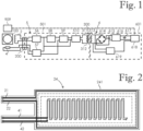
- Figure 1 shows a connection diagram of an electric machine configuration comprising an electric machine 100 and a data acquisition assembly connected to the electric machine 100.
- the data acquisition assembly comprises an auxiliary coil 2, a sensor 4, an intermediate circuit device 5 and a data acquisition device 6.
- the electric machine 100 is a rotating electric machine comprising a frame, a stator immovably supported to the frame, and a rotor received in the stator, and rotatably supported to the frame.
- the auxiliary coil 2 is located adjacent to the stator of the electric machine 100, and adapted to generate an auxiliary coil voltage during operation of the electric machine 100. During operation of the electric machine 100, a changing magnetic flux in the stator induces the auxiliary coil voltage in the auxiliary coil 2.
- the sensor 4 comprises a temperature sensor adapted for measuring a temperature relating to the electric machine 100, and for generating sensor information based on the measured temperature.
- the sensor is adapted for measuring at least one physical quantity relating to the electric machine, and for generating sensor information based on the measured at least one physical quantity.
- Both the auxiliary coil 2 and the temperature sensor are incorporated into a combined strip element 24 shown in Figure 2 .
- the combined strip element 24 is located in an air gap of the electric machine 100.
- the air gap is a space between the rotor and the stator of the electric machine 100.
- the combined strip element 24 is adhesively mounted to an inner surface of the stator of the electric machine 100.
- the combined strip element 24 has a planar and rectangular body section 241, from which wires 21 and 22 of the auxiliary coil 2, and wires 41 and 42 of the temperature sensor protrude from.
- a length of the rectangular body section 241 is 15cm, a width of the rectangular body section 241 is 5cm, and a thickness of the rectangular body section 241 is less than 0.1mm.
- a length of the body section is in a range of 1-50cm, a width of the body section is in a range of 1-50cm, and a thickness of the body section is less than or equal to 2mm.
- an internal structure of the combined strip element 24 is shown as a simplified version.
- the combined strip element 24 comprises dozens of metres of wiring, and therefore it is not possible to depict the internal structure in real form.
- amount of wiring inside the combined strip element varies from few centimetres to hundreds of meters depending on characteristics of the electric machine, the intermediate circuit device and the data acquisition device, for example.
- internal wiring of the combined strip element is realized as printed electronics.
- the combined strip element 24 is connected to the intermediate circuit device 5 through a terminal box 200, which provides a hermetic feedthrough into a housing 501 of the intermediate circuit device 5.
- Signals of wires 21 and 22 of the auxiliary coil 2, and signals of wires 41 and 42 of the temperature sensor pass through a terminal box 200.
- the auxiliary coil and the temperature sensor are separate components.
- neither the auxiliary coil nor the temperature sensor is located in an air gap of the electric machine.
- the auxiliary coil can be located around a portion of one of the plurality of stator teeth as discussed in European patent application EP22207177.1 .
- the intermediate circuit device 5 comprises a power supply 56, a sensor circuit 57, an oscillator 58, a modulator 59 and an amplifier 510.
- the wires 21 and 22 of the auxiliary coil 2 are electrically connected to an input of the power supply 56.
- the power supply 56 is adapted to supply regulated power through an output thereof.
- the output of the power supply 56 is electrically connected to the sensor circuit 57, to the oscillator 58, to the modulator 59 and to the amplifier 510.
- An input of the sensor circuit 57 is communicatively connected to the wires 41 and 42 of the temperature sensor through the terminal box 200.
- the sensor circuit 57 is adapted to convert an output signal of the sensor 4 into a sensor circuit signal that is adapted to control the modulator 59.
- An output of the sensor circuit 57 is communicatively connected to an input of the modulator 59.
- a coupling transformer 300 is adapted to transfer the combined signal generated by the intermediate circuit device 5 to the data acquisition device 6. All communication between the sensor 4 and the data acquisition device 6, and between the intermediate circuit device 5 and the data acquisition device 6 is adapted to be carried out through the coupling transformer 300.
- the coupling transformer 300 comprises a primary winding 311, a secondary winding 313, and a transformer core 312.
- the coupling transformer 300 does not change AC voltage levels.
- the coupling transformer is a step-up transformer or a step-down transformer.
- the data acquisition device 6 comprises a rectifier 614, a capacitor 615, a battery charger 616, a battery 617, a smart sensor circuitry 618 and a demodulator 619. There is galvanic separation between the data acquisition device 6 and the intermediate circuit device 5.
- a housing 601 of the data acquisition device 6 has an Ingress Protection Rating of IP66.
- a housing of the data acquisition device has an Ingress Protection Rating of at least IP54.
- Input of the demodulator 619 is electrically connected to the secondary winding 313.
- the demodulator 619 is adapted to sample a signal received from the secondary winding 313, and to extract the sensor information encoded by the modulator 59.
- the demodulator 619 is adapted to supply the extracted sensor information to the smart sensor circuitry 618.
- the smart sensor circuitry 618 is adapted to monitor condition of the electric machine 100 based on the sensor information.
- the data acquisition assembly comprises a plurality of sensors each adapted for measuring at least one physical quantity relating to the electric machine, wherein the data acquisition device is adapted to receive information from the plurality of sensors.
- the smart sensor circuitry is adapted to monitor condition of the electric machine based on sensor information generated by the plurality of sensors.
- the data acquisition device 6 is communicatively connected to a controller 909 and adapted to transmit information to the controller 909, wherein the information comprises the sensor information.
- the information which the data acquisition device is adapted to transmit to the controller comprises at least part of the sensor information or condition monitoring information processed from the sensor information.
- Figure 3 shows a simplified cross-section of an electric machine configuration comprising components shown in the connection diagram of Figure 1 .
- Figure 3 shows that the primary winding 311 and the transformer core 312 are located inside the housing 501 of the intermediate circuit device 5, and the secondary winding 313 is located inside the housing 601 of the data acquisition device 6.
- the primary winding 311' and the secondary winding 313' are located coaxially.
- the primary winding 311' and the secondary winding 313' are spaced apart in an axial direction.
Landscapes
- Engineering & Computer Science (AREA)
- Power Engineering (AREA)
- Physics & Mathematics (AREA)
- General Physics & Mathematics (AREA)
- Microelectronics & Electronic Packaging (AREA)
Abstract
A data acquisition assembly for an electric machine configuration comprising an auxiliary coil (2); at least one sensor (4); a data acquisition device (6); and an intermediate circuit device (5), wherein the auxiliary coil (2) is adapted to supply power to the data acquisition device (6) through the intermediate circuit device (5), and wherein the intermediate circuit device (5) is adapted to transfer information from the at least one sensor (4) to the data acquisition device (6). The intermediate circuit device (5) is adapted to generate a combined signal comprising both power from the auxiliary coil (2) and sensor information from the at least one sensor (4), wherein a frequency of the combined signal is greater than 20kHz. The data acquisition assembly comprises a coupling transformer (300) adapted to transfer the combined signal from the intermediate circuit device (5) to the data acquisition device (6).
Description
- The present invention relates to a data acquisition assembly for an electric machine configuration, and to the electric machine configuration comprising an electric machine and the data acquisition assembly.
- A known data acquisition assembly comprises at least one sensor adapted for measuring at least one physical quantity relating to an electric machine, and a data acquisition device adapted to receive information from the at least one sensor. The known data acquisition assembly comprises a non-replaceable battery adapted to power the data acquisition assembly. The non-replaceable battery provides up to 15 years of low data-rate use.
- One of the disadvantages associated with the above known data acquisition assembly is that the non-replaceable battery does not allow functions that require substantially more power. Therefore, increasing data rates or wireless communication range is practically not possible.
- An object of the present invention is to provide a data acquisition assembly for an electric machine configuration so as to alleviate the above disadvantage. The objects of the invention are achieved by a data acquisition assembly which is characterized by what is stated in the independent claim 1. The preferred embodiments of the invention are disclosed in the dependent claims.
- The invention is based on the idea of powering the data acquisition assembly by an auxiliary coil located adjacent to a stator of an electric machine, and transferring both power from the auxiliary coil and sensor information from at least one sensor to the data acquisition device in a form of a combined signal having a frequency greater than 20kHz, wherein the data acquisition assembly comprises a coupling transformer adapted to transfer the combined signal to the data acquisition device.
- An advantage of the data acquisition assembly of the invention is that the auxiliary coil is capable of providing plenty of power to devices of the data acquisition assembly, thereby enabling functions that are practically not possible in the known data acquisition assembly powered by a non-replaceable battery. Further, the coupling transformer enables high Ingress Protection Rating for the data acquisition device since both power and the sensor information is transmitted to the data acquisition device without any galvanic connection.
- In the following the invention will be described in greater detail by means of preferred embodiments with reference to the attached drawings, in which
-
Figure 1 shows a connection diagram of an electric machine configuration comprising a data acquisition assembly according to an embodiment of present invention; -
Figure 2 shows a combined strip element of the data acquisition assembly ofFigure 1 ; -
Figure 3 shows a simplified cross-section of an electric machine configuration comprising components shown in the connection diagram ofFigure 1 ; and -
Figure 4 shows a simplified cross-section of an electric machine configuration according to another embodiment of present invention, and comprising corresponding components as shown in the connection diagram ofFigure 1 . -
Figure 1 shows a connection diagram of an electric machine configuration comprising anelectric machine 100 and a data acquisition assembly connected to theelectric machine 100. The data acquisition assembly comprises anauxiliary coil 2, a sensor 4, anintermediate circuit device 5 and a data acquisition device 6. Theelectric machine 100 is a rotating electric machine comprising a frame, a stator immovably supported to the frame, and a rotor received in the stator, and rotatably supported to the frame. - The
auxiliary coil 2 is located adjacent to the stator of theelectric machine 100, and adapted to generate an auxiliary coil voltage during operation of theelectric machine 100. During operation of theelectric machine 100, a changing magnetic flux in the stator induces the auxiliary coil voltage in theauxiliary coil 2. - The sensor 4 comprises a temperature sensor adapted for measuring a temperature relating to the
electric machine 100, and for generating sensor information based on the measured temperature. In an alternative embodiment, the sensor is adapted for measuring at least one physical quantity relating to the electric machine, and for generating sensor information based on the measured at least one physical quantity. - Both the
auxiliary coil 2 and the temperature sensor are incorporated into a combinedstrip element 24 shown inFigure 2 . In the electric machine configuration ofFigure 1 , the combinedstrip element 24 is located in an air gap of theelectric machine 100. The air gap is a space between the rotor and the stator of theelectric machine 100. The combinedstrip element 24 is adhesively mounted to an inner surface of the stator of theelectric machine 100. - The combined
strip element 24 has a planar andrectangular body section 241, from whichwires auxiliary coil 2, andwires rectangular body section 241 is 15cm, a width of therectangular body section 241 is 5cm, and a thickness of therectangular body section 241 is less than 0.1mm. In alternative embodiments, a length of the body section is in a range of 1-50cm, a width of the body section is in a range of 1-50cm, and a thickness of the body section is less than or equal to 2mm. - In
Figure 2 , an internal structure of the combinedstrip element 24 is shown as a simplified version. The combinedstrip element 24 comprises dozens of metres of wiring, and therefore it is not possible to depict the internal structure in real form. In alternative embodiments, amount of wiring inside the combined strip element varies from few centimetres to hundreds of meters depending on characteristics of the electric machine, the intermediate circuit device and the data acquisition device, for example. - In an embodiment, internal wiring of the combined strip element is realized as printed electronics.
- The combined
strip element 24 is connected to theintermediate circuit device 5 through aterminal box 200, which provides a hermetic feedthrough into ahousing 501 of theintermediate circuit device 5. Signals ofwires auxiliary coil 2, and signals ofwires terminal box 200. - In an alternative embodiment, the auxiliary coil and the temperature sensor are separate components. In an embodiment, neither the auxiliary coil nor the temperature sensor is located in an air gap of the electric machine. For example, the auxiliary coil can be located around a portion of one of the plurality of stator teeth as discussed in European patent application
EP22207177.1 - The
intermediate circuit device 5 is adapted to generate a combined signal comprising both power from theauxiliary coil 2 and sensor information from the sensor 4, and to transfer the combined signal to the data acquisition device 6. The power from theauxiliary coil 2 is provided by the auxiliary coil voltage. Theintermediate circuit device 5 is adapted to transfer power from theauxiliary coil 2 to the data acquisition device 6, and to transfer sensor information from the sensor 4 to the data acquisition device 6. Theintermediate circuit device 5 and the data acquisition device 6 are powered by theauxiliary coil 2. - The
intermediate circuit device 5 comprises apower supply 56, asensor circuit 57, anoscillator 58, amodulator 59 and anamplifier 510. Thewires auxiliary coil 2 are electrically connected to an input of thepower supply 56. - The
power supply 56 is adapted to supply regulated power through an output thereof. The output of thepower supply 56 is electrically connected to thesensor circuit 57, to theoscillator 58, to themodulator 59 and to theamplifier 510. - An input of the
sensor circuit 57 is communicatively connected to thewires terminal box 200. Thesensor circuit 57 is adapted to convert an output signal of the sensor 4 into a sensor circuit signal that is adapted to control themodulator 59. An output of thesensor circuit 57 is communicatively connected to an input of themodulator 59. - The
oscillator 58 is adapted to generate a continuous carrier frequency greater than 20kHz. An output of theoscillator 58 is communicatively connected to an input of themodulator 59. Themodulator 59 is adapted to modulate the continuous carrier frequency, and theamplifier 510 is adapted to amplify the modulated signal. An input of theamplifier 510 is communicatively connected to an output of themodulator 59. An output signal of theamplifier 510 is the combined signal. - A
coupling transformer 300 is adapted to transfer the combined signal generated by theintermediate circuit device 5 to the data acquisition device 6. All communication between the sensor 4 and the data acquisition device 6, and between theintermediate circuit device 5 and the data acquisition device 6 is adapted to be carried out through thecoupling transformer 300. Thecoupling transformer 300 comprises aprimary winding 311, asecondary winding 313, and atransformer core 312. - The
primary winding 311 and thesecondary winding 313 have the same number of turns. Therefore, thecoupling transformer 300 does not change AC voltage levels. In alternative embodiments, the coupling transformer is a step-up transformer or a step-down transformer. - The data acquisition device 6 comprises a
rectifier 614, acapacitor 615, abattery charger 616, abattery 617, asmart sensor circuitry 618 and ademodulator 619. There is galvanic separation between the data acquisition device 6 and theintermediate circuit device 5. Ahousing 601 of the data acquisition device 6 has an Ingress Protection Rating of IP66. In an alternative embodiment, a housing of the data acquisition device has an Ingress Protection Rating of at least IP54. - Input of the
rectifier 614 is electrically connected to the secondary winding 313. Therectifier 614 is adapted to rectify power received from the secondary winding 313, and to supply the rectified power to thebattery charger 616. Thecapacitor 615 is electrically connected between therectifier 614 and thebattery charger 616, and is adapted to filter the power supplied from therectifier 614 to thebattery charger 616. Thebattery charger 616 is adapted to condition the power received from therectifier 614, and to supply the conditioned power to thebattery 617 for charging thebattery 617. Thesmart sensor circuitry 618 is adapted to draw power from thebattery 617 as needed. - Input of the
demodulator 619 is electrically connected to the secondary winding 313. Thedemodulator 619 is adapted to sample a signal received from the secondary winding 313, and to extract the sensor information encoded by themodulator 59. Thedemodulator 619 is adapted to supply the extracted sensor information to thesmart sensor circuitry 618. Thesmart sensor circuitry 618 is adapted to monitor condition of theelectric machine 100 based on the sensor information. - In an alternative embodiment, the data acquisition assembly comprises a plurality of sensors each adapted for measuring at least one physical quantity relating to the electric machine, wherein the data acquisition device is adapted to receive information from the plurality of sensors. The smart sensor circuitry is adapted to monitor condition of the electric machine based on sensor information generated by the plurality of sensors.
- The data acquisition device 6 is communicatively connected to a
controller 909 and adapted to transmit information to thecontroller 909, wherein the information comprises the sensor information. In alternative embodiments, the information which the data acquisition device is adapted to transmit to the controller comprises at least part of the sensor information or condition monitoring information processed from the sensor information. - The
controller 909 is adapted to control theelectric machine 100 based on the information received from the data acquisition device 6. If the sensor information indicates that a temperature of theelectric machine 100 is greater than a predetermined limit value, thecontroller 909 decreases power of theelectric machine 100, or switches off theelectric machine 100. In an alternative embodiment, the controller is adapted to utilize the information received from the data acquisition device for monitoring condition of the electric machine. -
Figure 3 shows a simplified cross-section of an electric machine configuration comprising components shown in the connection diagram ofFigure 1 .Figure 3 shows that the primary winding 311 and thetransformer core 312 are located inside thehousing 501 of theintermediate circuit device 5, and the secondary winding 313 is located inside thehousing 601 of the data acquisition device 6. - The primary winding 311 and the secondary winding 313 are located coaxially. The primary winding 311 is located radially inside the secondary winding 313. The primary winding 311 and the secondary winding 313 overlap in an axial direction.
- The data acquisition device 6 is mechanically connected to the
intermediate circuit device 5 by a bolt joint comprising a mountingbolt 71 and an internal thread provided in thetransformer core 312. Thehousing 601 of the data acquisition device 6 has a bolt hole adapted to receive an external thread of the mountingbolt 71. The mountingbolt 71 has acollar 712 that is adapted to cooperate with a section of thehousing 601 around the bolt hole for pressing the data acquisition device 6 against theintermediate circuit device 5. -
Figure 4 shows a simplified cross-section of an electric machine configuration according to another embodiment of present invention, and comprising corresponding components as shown in the connection diagram ofFigure 1 .Fig-ure 4 shows that the primary winding 311' and the transformer core 312' are located inside the housing 501' of the intermediate circuit device 5', and the secondary winding 313' is located inside the housing 601' of the data acquisition device 6'. - The primary winding 311' and the secondary winding 313' are located coaxially. The primary winding 311' and the secondary winding 313' are spaced apart in an axial direction.
- In
Figures 3 and 4 , components inside the intermediate circuit device and the data acquisition device have been omitted except for components relating to the coupling transformer. Further, only a portion of the electric machine is shown. - It will be obvious to a person skilled in the art that the inventive concept can be implemented in various ways. The invention and its embodiments are not limited to the examples described above but may vary within the scope of the claims.
Claims (12)
- A data acquisition assembly for an electric machine configuration comprisingan auxiliary coil (2) adapted to be located adjacent to a stator of an electric machine (100), and adapted to generate an auxiliary coil voltage during operation of the electric machine (100);at least one sensor (4) adapted for measuring at least one physical quantity relating to the electric machine (100);a data acquisition device (6) adapted to receive information from the at least one sensor (4); andan intermediate circuit device (5), wherein the auxiliary coil (2) is adapted to supply power to the data acquisition device (6) through the intermediate circuit device (5), and wherein the intermediate circuit device (5) is adapted to transfer information from the at least one sensor (4) to the data acquisition device (6),characterized in that the intermediate circuit device (5) is adapted to generate a combined signal comprising both power from the auxiliary coil (2) and sensor information from the at least one sensor (4), wherein a frequency of the combined signal is greater than 20kHz,wherein the data acquisition assembly comprises a coupling transformer (300) adapted to transfer the combined signal from the intermediate circuit device (5) to the data acquisition device (6).
- The data acquisition assembly according to claim 1, wherein all communication between the at least one sensor (4) and the data acquisition device (6), and between the intermediate circuit device (5) and the data acquisition device (6) is adapted to be carried out through the coupling transformer (300).
- The data acquisition assembly according to claim 1 or 2, wherein the at least one sensor (4) comprises a temperature sensor.
- The data acquisition assembly according to claim 3, wherein the data acquisition assembly comprises a combined strip element (24) having both the auxiliary coil (2) and the temperature sensor.
- The data acquisition assembly according to claim 4, wherein the combined strip element (24) is adapted to be located in an air gap of the electric machine (100), and to be adhesively mounted to an inner surface of the stator of the electric machine (100).
- The data acquisition assembly according to any one of the preceding claims, wherein a primary winding (311) of the coupling transformer (300) is located inside the housing (501) of the intermediate circuit device (5), and a secondary winding (313) of the coupling transformer (300) is located inside a housing (601) of the data acquisition device (6).
- The data acquisition assembly according to any one of the preceding claims, wherein the data acquisition assembly comprises a controller (909) adapted to control the electric machine (100), wherein the data acquisition device (6) is communicatively connected to the controller (909) and adapted to transmit information to the controller (909).
- The data acquisition assembly according to claim 7, wherein the information transmitted from the data acquisition device (6) to the controller (909) comprises at least part of the sensor information or condition monitoring information processed from the sensor information.
- The data acquisition assembly according to claim 7 or 8, wherein the controller (909) is adapted to control the electric machine (100) based on the information received from the data acquisition device (6).
- The data acquisition assembly according to any one of claims 7 to 9, wherein the controller (909) is adapted to utilize the information received from the data acquisition device (6) for monitoring condition of the electric machine (100).
- A combined strip element for a data acquisition assembly according to claim 3, wherein the combined strip element (24) comprises both the auxiliary coil (2) and the temperature sensor.
- An electric machine configuration comprising an electric machine (100) and the data acquisition assembly according to any one of claims 1-10.
Priority Applications (1)
| Application Number | Priority Date | Filing Date | Title |
|---|---|---|---|
| EP23198177.0A EP4528241A1 (en) | 2023-09-19 | 2023-09-19 | Data acquisition assembly for electric machine configuration, and electric machine configuration comprising the same |
Applications Claiming Priority (1)
| Application Number | Priority Date | Filing Date | Title |
|---|---|---|---|
| EP23198177.0A EP4528241A1 (en) | 2023-09-19 | 2023-09-19 | Data acquisition assembly for electric machine configuration, and electric machine configuration comprising the same |
Publications (1)
| Publication Number | Publication Date |
|---|---|
| EP4528241A1 true EP4528241A1 (en) | 2025-03-26 |
Family
ID=88097698
Family Applications (1)
| Application Number | Title | Priority Date | Filing Date |
|---|---|---|---|
| EP23198177.0A Pending EP4528241A1 (en) | 2023-09-19 | 2023-09-19 | Data acquisition assembly for electric machine configuration, and electric machine configuration comprising the same |
Country Status (1)
| Country | Link |
|---|---|
| EP (1) | EP4528241A1 (en) |
Citations (4)
| Publication number | Priority date | Publication date | Assignee | Title |
|---|---|---|---|---|
| WO2010136052A1 (en) * | 2009-05-26 | 2010-12-02 | Siemens Aktiengesellschaft | Electrotechnical consumer and use of an induction coil |
| DE102018220676A1 (en) * | 2018-11-30 | 2020-06-04 | Robert Bosch Gmbh | Rotor of an electric motor with a temperature sensor |
| EP4125190A1 (en) * | 2021-07-30 | 2023-02-01 | voestalpine Automotive Components Dettingen GmbH & Co. KG | Electric motor comprising an energy-harvesting device |
| DE102021212604A1 (en) * | 2021-11-09 | 2023-05-11 | Zf Friedrichshafen Ag | electrical machine |
-
2023
- 2023-09-19 EP EP23198177.0A patent/EP4528241A1/en active Pending
Patent Citations (4)
| Publication number | Priority date | Publication date | Assignee | Title |
|---|---|---|---|---|
| WO2010136052A1 (en) * | 2009-05-26 | 2010-12-02 | Siemens Aktiengesellschaft | Electrotechnical consumer and use of an induction coil |
| DE102018220676A1 (en) * | 2018-11-30 | 2020-06-04 | Robert Bosch Gmbh | Rotor of an electric motor with a temperature sensor |
| EP4125190A1 (en) * | 2021-07-30 | 2023-02-01 | voestalpine Automotive Components Dettingen GmbH & Co. KG | Electric motor comprising an energy-harvesting device |
| DE102021212604A1 (en) * | 2021-11-09 | 2023-05-11 | Zf Friedrichshafen Ag | electrical machine |
Similar Documents
| Publication | Publication Date | Title |
|---|---|---|
| JP7102396B2 (en) | Wireless connector system | |
| CN103094995B (en) | Wireless Power Transmission Device | |
| US6573707B2 (en) | Displacement detecting device power supply and data communication device | |
| JP6977654B2 (en) | Wireless power receiving device and wireless power transmission system | |
| CN215932098U (en) | Integrated transformer core grounding current monitoring system capable of self-energy taking | |
| CN101431258A (en) | Power transferring coil unit, mobile terminal, power transmitting apparatus, and power transferring system | |
| CN104798314B (en) | Modular electronic systems and bus user equipment | |
| EP4528241A1 (en) | Data acquisition assembly for electric machine configuration, and electric machine configuration comprising the same | |
| CN102782458A (en) | Bearing current sensor device having an energy converter | |
| CN207304096U (en) | Electronic cigarette wireless charging device and electronic cigarette system | |
| US12139020B2 (en) | Device and method for supplying energy to a sensor device in a rail vehicle | |
| US12142940B2 (en) | Cross talk and interference mitigation in dual wireless power transmitter | |
| WO2022165359A1 (en) | Wirelessly powered sensor system | |
| CN102570842B (en) | Three-phase metering system and method thereof | |
| KR19990077043A (en) | Modular core self-powered powerline sensor | |
| KR100898059B1 (en) | Wireless Mouse Set and / or Small Electronic Device Set Using Wireless Power | |
| JPH11176676A (en) | Small contactless transmission device | |
| KR20090066385A (en) | Embedded contactless signal coupling device for power line communication | |
| WO2008082943A1 (en) | Wireless scanner system, head and method | |
| CN111845217B (en) | Tire pressure and tire temperature monitoring system and device for aircraft | |
| CN113489165A (en) | Non-contact type rotating body electric energy transmission and communication device and electric moped | |
| KR100539013B1 (en) | A wireless mouse charging with induction coil | |
| CN215870920U (en) | Active RFID electronic tag charging system and cabinet | |
| EP4576496A1 (en) | Underwater module charging | |
| CN108291928A (en) | Induction type current mutual inductor |
Legal Events
| Date | Code | Title | Description |
|---|---|---|---|
| PUAI | Public reference made under article 153(3) epc to a published international application that has entered the european phase |
Free format text: ORIGINAL CODE: 0009012 |
|
| STAA | Information on the status of an ep patent application or granted ep patent |
Free format text: STATUS: THE APPLICATION HAS BEEN PUBLISHED |
|
| AK | Designated contracting states |
Kind code of ref document: A1 Designated state(s): AL AT BE BG CH CY CZ DE DK EE ES FI FR GB GR HR HU IE IS IT LI LT LU LV MC ME MK MT NL NO PL PT RO RS SE SI SK SM TR |
|
| STAA | Information on the status of an ep patent application or granted ep patent |
Free format text: STATUS: REQUEST FOR EXAMINATION WAS MADE |
|
| 17P | Request for examination filed |
Effective date: 20250619 |