EP4528218A1 - Tracking marker - Google Patents
Tracking marker Download PDFInfo
- Publication number
- EP4528218A1 EP4528218A1 EP23199141.5A EP23199141A EP4528218A1 EP 4528218 A1 EP4528218 A1 EP 4528218A1 EP 23199141 A EP23199141 A EP 23199141A EP 4528218 A1 EP4528218 A1 EP 4528218A1
- Authority
- EP
- European Patent Office
- Prior art keywords
- tracking
- color
- tracking marker
- space
- fiducial
- Prior art date
- Legal status (The legal status is an assumption and is not a legal conclusion. Google has not performed a legal analysis and makes no representation as to the accuracy of the status listed.)
- Granted
Links
Images


Classifications
-
- G—PHYSICS
- G01—MEASURING; TESTING
- G01B—MEASURING LENGTH, THICKNESS OR SIMILAR LINEAR DIMENSIONS; MEASURING ANGLES; MEASURING AREAS; MEASURING IRREGULARITIES OF SURFACES OR CONTOURS
- G01B11/00—Measuring arrangements characterised by the use of optical techniques
- G01B11/24—Measuring arrangements characterised by the use of optical techniques for measuring contours or curvatures
-
- G—PHYSICS
- G01—MEASURING; TESTING
- G01S—RADIO DIRECTION-FINDING; RADIO NAVIGATION; DETERMINING DISTANCE OR VELOCITY BY USE OF RADIO WAVES; LOCATING OR PRESENCE-DETECTING BY USE OF THE REFLECTION OR RERADIATION OF RADIO WAVES; ANALOGOUS ARRANGEMENTS USING OTHER WAVES
- G01S17/00—Systems using the reflection or reradiation of electromagnetic waves other than radio waves, e.g. lidar systems
- G01S17/02—Systems using the reflection of electromagnetic waves other than radio waves
- G01S17/06—Systems determining position data of a target
- G01S17/42—Simultaneous measurement of distance and other co-ordinates
-
- G—PHYSICS
- G01—MEASURING; TESTING
- G01S—RADIO DIRECTION-FINDING; RADIO NAVIGATION; DETERMINING DISTANCE OR VELOCITY BY USE OF RADIO WAVES; LOCATING OR PRESENCE-DETECTING BY USE OF THE REFLECTION OR RERADIATION OF RADIO WAVES; ANALOGOUS ARRANGEMENTS USING OTHER WAVES
- G01S17/00—Systems using the reflection or reradiation of electromagnetic waves other than radio waves, e.g. lidar systems
- G01S17/66—Tracking systems using electromagnetic waves other than radio waves
-
- G—PHYSICS
- G01—MEASURING; TESTING
- G01S—RADIO DIRECTION-FINDING; RADIO NAVIGATION; DETERMINING DISTANCE OR VELOCITY BY USE OF RADIO WAVES; LOCATING OR PRESENCE-DETECTING BY USE OF THE REFLECTION OR RERADIATION OF RADIO WAVES; ANALOGOUS ARRANGEMENTS USING OTHER WAVES
- G01S17/00—Systems using the reflection or reradiation of electromagnetic waves other than radio waves, e.g. lidar systems
- G01S17/86—Combinations of lidar systems with systems other than lidar, radar or sonar, e.g. with direction finders
-
- G—PHYSICS
- G01—MEASURING; TESTING
- G01S—RADIO DIRECTION-FINDING; RADIO NAVIGATION; DETERMINING DISTANCE OR VELOCITY BY USE OF RADIO WAVES; LOCATING OR PRESENCE-DETECTING BY USE OF THE REFLECTION OR RERADIATION OF RADIO WAVES; ANALOGOUS ARRANGEMENTS USING OTHER WAVES
- G01S17/00—Systems using the reflection or reradiation of electromagnetic waves other than radio waves, e.g. lidar systems
- G01S17/88—Lidar systems specially adapted for specific applications
- G01S17/89—Lidar systems specially adapted for specific applications for mapping or imaging
-
- G—PHYSICS
- G01—MEASURING; TESTING
- G01S—RADIO DIRECTION-FINDING; RADIO NAVIGATION; DETERMINING DISTANCE OR VELOCITY BY USE OF RADIO WAVES; LOCATING OR PRESENCE-DETECTING BY USE OF THE REFLECTION OR RERADIATION OF RADIO WAVES; ANALOGOUS ARRANGEMENTS USING OTHER WAVES
- G01S7/00—Details of systems according to groups G01S13/00, G01S15/00, G01S17/00
- G01S7/48—Details of systems according to groups G01S13/00, G01S15/00, G01S17/00 of systems according to group G01S17/00
- G01S7/481—Constructional features, e.g. arrangements of optical elements
-
- G—PHYSICS
- G06—COMPUTING OR CALCULATING; COUNTING
- G06T—IMAGE DATA PROCESSING OR GENERATION, IN GENERAL
- G06T7/00—Image analysis
- G06T7/50—Depth or shape recovery
- G06T7/55—Depth or shape recovery from multiple images
-
- A—HUMAN NECESSITIES
- A61—MEDICAL OR VETERINARY SCIENCE; HYGIENE
- A61B—DIAGNOSIS; SURGERY; IDENTIFICATION
- A61B34/00—Computer-aided surgery; Manipulators or robots specially adapted for use in surgery
- A61B34/20—Surgical navigation systems; Devices for tracking or guiding surgical instruments, e.g. for frameless stereotaxis
- A61B2034/2046—Tracking techniques
- A61B2034/2055—Optical tracking systems
-
- G—PHYSICS
- G01—MEASURING; TESTING
- G01S—RADIO DIRECTION-FINDING; RADIO NAVIGATION; DETERMINING DISTANCE OR VELOCITY BY USE OF RADIO WAVES; LOCATING OR PRESENCE-DETECTING BY USE OF THE REFLECTION OR RERADIATION OF RADIO WAVES; ANALOGOUS ARRANGEMENTS USING OTHER WAVES
- G01S7/00—Details of systems according to groups G01S13/00, G01S15/00, G01S17/00
- G01S7/48—Details of systems according to groups G01S13/00, G01S15/00, G01S17/00 of systems according to group G01S17/00
- G01S7/4808—Evaluating distance, position or velocity data
Definitions
- the present disclosure relates to a tracking marker and a method for use thereof in a system, and a method for scanning a three dimensional space. It also relates to a mobile device and a post processing unit for use with a mobile device.
- the present disclosure relates to a method and system for three dimensional, 3D, space scanning and modeling based on a tracking marker integrated with a color checker, also known as a color correction card.
- 3D space scanning and modeling is a technique that uses advanced technology to capture and create a 3D digital model of a physical space.
- Tracking marker technology is a technique used to track the position of objects in a three-dimensional space. This technology involves placing a plurality of markers on the objects, which are then tracked by a camera. It has been already proven to be a useful tool in various industries such as film, gaming, and advertising.
- tracking marker technology is becoming more accurate and efficient, allowing for a more realistic and immersive experience.
- a color checker also known as a color correction card, is a reference tool used to ensure that the colors in an image or video are accurate and consistent. It is typically a small card or chart that contains a set of color swatches, which are designed to represent a range of colors that are commonly found in real-world scenes.
- the color checker is photographed or filmed alongside the scene or subject, and the resulting image or footage is then used as a reference for color correction during post-production.
- colorists can adjust the color balance and saturation to achieve a more accurate and consistent look.
- color checker is particularly important in applications such as film and photography where color accuracy is critical.
- 3D space scanning requires capturing multiple images with different angles and distances in order to cover a wide range of space, i.e., from bottom, i.e., floor, to top, i.e., ceiling, and up to 360 degrees of horizontal direction.
- color inconsistency is a common problem that can occur when capturing images in 360 degrees of view. This is because the lighting conditions and color temperature can vary significantly across the entire space, resulting in color variations that can be difficult to correct in post-production. In addition, the camera's white balance settings may not be able to accurately capture the full range of colors in the scenes, leading to color shifts and inconsistencies.
- Another factor that can contribute to color inconsistency is the texture mapping process used to combine the individual images into a seamless 360-degree of mesh object.
- Position tracking or SLAM, Simultaneous Localization and Mapping, using a mobile phone alone can suffer from drift errors due to several factors that can affect the accuracy of the position tracking.
- One of the main factors is the limitations of the sensors built into the mobile phone, such as the accelerometer, gyroscope, and magnetometer.
- Said poor position tracking and/or SLAM performance prevents from the mass and direct utilization of a mobile phone in 3D space scanning and modeling.
- a tracking marker comprising: a fiducial section for providing a reference scale in at least two dimensions and an orientation reference; and at least one color swatch with a plurality of color swatch elements for providing a color reference, wherein the tracking marker is preferably configured to be attached to an object in a 3D space.
- the at least one color swatch comprises at least one of: a set of natural colors, a set of primary and secondary colors, a set of grayscale colors, and a set of miscellaneous colors, wherein preferably each color swatch comprises six or more colors swatch elements.
- the tracking marker is a two-dimensional tracking marker and the fiducial section provides a reference scale in each of the two dimensions of the tracking marker.
- the fiducial section is a cut-out in a central portion of the tracking marker, and the at least one color swatch is arranged to surround the fiducial section.
- the tracking marker has a square shape with a side length A, and the tracking marker area is divided into n by m rectangular area elements with side lengths of A/n in a first direction and AIm in a second direction, with n and m being integer numbers, with n being preferably 6 and m being preferably 5.
- the tracking marker comprises four color swatches and each color swatch comprises a same number of color swatch elements each corresponding to one rectangular area element, and the fiducial section is a cut-out of the same number of rectangular area elements in the central portion of the tracking marker.
- a mobile device for scanning a 3D space provided with a plurality of tracking markers comprising: a camera configured to acquire a plurality of digital images of at least a part of the 3D space; and a depth sensor configured to acquire corresponding depth data of the 3D space, wherein the mobile device comprises or is connected to a post processing unit configured to correct the colors and/or white balance of the acquired images based on the at least one color swatch of the tracking markers; and perform texture mapping based on the acquired images and based on position tracking data based on the fiducial section of the tracking markers.
- a post processing unit for use with a mobile device according to claim 8 for scanning a 3D space provided with a plurality of tracking markers according to any one of the preceding aspects and embodiments, wherein the post processing unit is configured to correct the colors and/or white balance of the acquired images based on the at least one color swatch of the tracking markers; and to perform texture mapping based on the acquired images and based on position tracking data based on the fiducial section of the tracking markers.
- a system for scanning a 3D space comprising: a plurality of tracking markers according to any one of the preceding aspects and embodiments arranged in the 3D space; a mobile device according to the above aspect; and a post processing unit according to the above aspect.
- a method for scanning a 3D space provided with a plurality of tracking markers comprising: acquiring with a camera of a mobile device a plurality of images of at least a part of the 3D space; acquiring corresponding depth data of the 3D space with a depth sensor of the mobile device; and performing a post processing comprising correcting the colors and/or white balance of the acquired images based on the at least one color swatch of the tracking markers; and performing texture mapping based on the acquired images and based on position tracking data based on the fiducial section of the tracking markers.
- the present disclosure enables the use of a mobile phone in a 3D scanning system and method.
- the system and method according to the present disclosure may enhance color and white balance calibration (correction), and also improves the position tracking of images captured from a mobile optical camera.
- the tracking marker is preferably configured to attached to an object in a 3D space.
- the tracking marker be provided on a substrate configured to be attached to a surface of the object.
- the substrate is a paper or plastic material on which the tracking marker according to the present invention is printable.
- the attachment may be releasable or permanent.
- the attachment may be an adhesive connection.
- the attachment may be a velcro connection.
- the attachment may be an electrostatic connection.
- the attachment may be a magnetic connection.
- a tracking marker integrated with a color checker is provided.
- This tracking marker may be used in a system and/or method for 3D space scanning and modeling through the most efficient, simplest, and direct way.
- Color checkers are particularly useful in situations where lighting conditions can vary significantly, such as indoor shoots with mixed lighting sources.
- a color checker By including a color checker in a scene, photographers and designers can capture an accurate reference of the colors in the scene, which can be used to correct for any color shifts or inconsistencies during post-production.
- tracking markers have several advantages over other position tracking technologies, including: Flexibility: Tracking markers can be placed on any object, making them flexible solution for a wide range of applications. This is particularly useful in situations where the objects being tracked are irregularly shaped or have complex movements.
- Tracking markers can provide highly accurate position tracking, particularly when used in conjunction with high-quality cameras and tracking software. This makes them an ideal solution for applications that require precise movement tracking, such as motion capture for film and gaming.
- Tracking markers can provide real-time position tracking with low latency, making them suitable for applications that require fast response times, such as robotics or virtual reality.
- Cost efficiency Tracking markers are often a more cost-effective solution than other position tracking technologies, such as GPS or LiDAR. This makes them a popular choice for applications where cost is a consideration.
- a tracking marker is combined with a color checker so that it can resolve two major technical challenges of 3D scanning, color inconsistency and poor position tracking performance.
- a smartphone may have sufficient computing power, especially when connected to edge computing resources or cloud computing resources.
- edge computing resources or cloud computing resources may have sufficient computing power, especially when connected to edge computing resources or cloud computing resources.
- Fig. 1 shows an embodiment of the tracking marker according to an embodiment of the present disclosure in colors and Fig. 2 shows the embodiment of the tracking marker of Fig. 1 with names and hex color codes of the colors.
- the tracking marker 100 comprises a solid area 300 and a cut-out 200.
- the solid area 300 comprises at least one color swatch with a plurality of color swatch elements.
- Fig. 1 shows a color representation of the color swatches 300.
- Fig. 2 shows the same embodiment with a name of the respective color as well as a hex color code of the respective color.
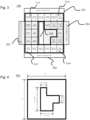
- Fig. 3 shows the position of color swatches on a tracking marker according to an embodiment of the present disclosure.
- the tracking marker comprises four color swatches 301, 302, 303 and 304 arranged in the solid area 300 of the tracking marker 100.
- the first color swatch 301 comprises natural colors.
- the second color swatch 302 comprises grayscale colors.
- the third color swatch 303 comprises primary and secondary colors.
- the fourth color swatch 304 comprises miscellaneous colors.
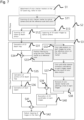
- Fig. 4 shows the fiducial marker on a tracking marker according to an embodiment of the present disclosure.
- a fiducial marker is formed by a cut-out 200 in the tracking marker 100.
- the cut-out is arranged in a central portion of the tracking marker 100.
- the fiducial marker is surrounded by the color swatches.
- cut-out encompasses a physical cut-out, i.e., removed material, as well as a relative cut-out.
- the latter being an area visually significantly different from the surrounding area, e.g., by a different color, preferably solid white, black, or green.
- the tracking marker 100 has a square shape with a side length of A.
- the tracking marker can be divided into m columns of equal width and n rows of equal height. n and m being integer numbers.
- the tracking marker 100 may be divided into n by m rectangular surface area elements 111 to 1nm. Each rectangular surface area element corresponding to a color swatch element or a portion of the cut-out.
- the number of rectangular area elements is the same in each of the color swatch and the cut-out.
- a first color swatch is arranged above the cut-out, a second color swatch is arranged below the cut-out, a third and fourth color swatch is arranged left and right of the cut-out. That is, the color swatches surround the fiducial marker.
- the first color swatch 301 is arranged on the rectangular area elements of the first row.
- the second color swatch 302 is preferably arranged on the rectangular area elements of the fifth row.
- the third color swatch 303 is preferably arranged on the rectangular area elements of the second, third, and fourth row in the first and second column.
- the fourth color swatch 304 is preferably arranged on the fourth to sixth rectangular area elements of the second row, on the sixth element of the third row, and the fifth and sixth rectangular area element of the fourth row.
- the remaining rectangular area elements are preferably forming the cut-out for the fiducial section 200.
- Fig. 5 illustrates an example that shows how to attach tracking markers integrated with a color checker in a 3D space, preferably an indoor space.
- the markers are provided such that at least one marker is visible in each image of the 3D scanning as discussed above. That is, the markers are provided about equally spaced in every view direction of the 3D scan, preferably the complete 3D space.
- Fig. 6 illustrates an example that shows how to scan a 3D space provided with tracking markers integrated with a color checker.
- the 3D space is scanned by a use of a hand-held mobile device 400, preferably a mobile phone.
- the mobile device is moved, as illustrated by the arrows 500, such that the build-in sensors, i.e. the depth sensor and/or camera captures a plurality of data and/or images covering the complete view direction of the 3D scan, preferably the complete 3D space.
- the build-in sensors i.e. the depth sensor and/or camera captures a plurality of data and/or images covering the complete view direction of the 3D scan, preferably the complete 3D space.
- Fig. 7 shows a flow diagram of a 3D scanning method according to an embodiment of the present disclosure.
- the method according to an embodiment of the present disclosure comprises the steps of providing tracking markers according to the present disclosure in the 3D space S1; the step of scanning the 3D space S2; the step of processing the scanned data S3.
- the 3D scanning is performed S2. That is, optionally first in an initialization step S11 at least one tracking marker is imaged with the camera of the mobile device and the scale and color settings of the camera are set based on the fiducial marker and/or the at least one color swatch S11. Alternatively, the camera may be used in auto-setting mode.
- the scanning with the depth sensor S12 and the acquisition of a plurality of images of the 3D space S13 is performed. Furthermore, the acquisition of a plurality camara images S13 is performed.
- the acquisition may include capturing, pre-processing, combining and/or saving a plurality of images of the 3D space.
- the acquisition may be performed during a continuous sweeping motion or stepwise, with or without additional guiding information, in order to sufficiently cover the entire scan area.
- the obtained depth data from step S12 and the obtained images from step S13 is post-processed to perform texture mapping and thus obtain 3D content from the 3D scan.
- step S31 a 3D depth map is generated based on the data from the depth sensor.
- step S32 a color data analysis is performed for each image of the plurality of images from step S13 based on the reference colors on the color swatches of the tracking markers.
- step S33 a position tracking is performed for each image of the plurality of images from step S13 based on the fiducial marker on the tracking markers.
- the original data about colors and scale based on the fiducial marker shall be the reference or fiducial to analyze the color inconsistency and measure the distance and the pose of the object.
- step S34 the position tracking data based on the fiducial marker on the tracking markers and the depth map data of step S31 is combined to calibrate a corrected 3D depth map in step S35.
- step S31 it is possible to have an initial 3D depth map.
- the initial 3D depth map will have many errors.
- step S33 process the precise distance data is analyzed and the precision of the 3D depth map is improved. Between two distance data, one from SLAM and the other from the marker, the distance measured from the marker has a higher priority.
- step 36 a mesh object is generated based on the calibrated 3D depth map of step S35.
- step 37 the plurality of images is color and/or white balance corrected based on the results of the color data analysis of step S32.
- step 38 the tracking markers are removed from the plurality of images and the resulting holes a patched.
- step 39 the calibrated 3D depth map, the position tracking data and the corrected images are combined for the association of UV coordinated on each image in step S40.
- a UV texture mapping process requires higher precision data. If the data would be of poor quality, e.g. merely the SLAM data, texture fragmentation or texture tearing with many broken seam and other inconsistencies will be observed.
- step S42 Finally the mesh object and UV coordinates are combined S41 and Texture mapping is performed in step S42.
- steps S2 and S3 may be performed on the mobile device 400.
- the post processing or parts thereof may be performed in connected processing instances, preferably in an edge cloud environment.
- any reference to an element herein using a designation such as "first,” “second,” and so forth does not generally limit the quantity or order of those elements. Rather, these designations can be used herein as a convenient means of distinguishing between two or more elements or instances of an element. Thus, a reference to first and second elements does not mean that only two elements can be employed, or that the first element must precede the second element in some manner.
- any one of the various illustrative logical blocks, units, processors, means, circuits, methods and functions described in connection with the aspects disclosed herein can be implemented by electronic hardware (e.g., a digital implementation, an analog implementation, or a combination of the two), firmware, various forms of program or design code incorporating instructions (which can be referred to herein, for convenience, as "software” or a "software unit”), or any combination of these techniques.
- a processor, device, component, circuit, structure, machine, unit, etc. can be configured to perform one or more of the functions described herein.
- IC integrated circuit
- DSP digital signal processor
- ASIC application specific integrated circuit
- FPGA field programmable gate array
- the logical blocks, units, and circuits can further include antennas and/or transceivers to communicate with various components within the network or within the device.
- a general purpose processor can be a microprocessor, but in the alternative, the processor can be any conventional processor, controller, or state machine.
- a processor can also be implemented as a combination of computing devices, e.g., a combination of a DSP and a microprocessor, a plurality of microprocessors, one or more microprocessors in conjunction with a DSP core, or any other suitable configuration to perform the functions described herein. If implemented in software, the functions can be stored as one or more instructions or code on a computer-readable medium. Thus, the steps of a method or algorithm disclosed herein can be implemented as software stored on a computer-readable medium.
- Computer-readable media includes both computer storage media and communication media including any medium that can be enabled to transfer a computer program or code from one place to another.
- a storage media can be any available media that can be accessed by a computer.
- such computer-readable media can include RAM, ROM, EEPROM, CD-ROM or other optical disk storage, magnetic disk storage or other magnetic storage devices, or any other medium that can be used to store desired program code in the form of instructions or data structures and that can be accessed by a computer.
- unit refers to software, firmware, hardware, and any combination of these elements for performing the associated functions described herein. Additionally, for purpose of discussion, the various units are described as discrete units; however, as would be apparent to one of ordinary skill in the art, two or more units may be combined to form a single unit that performs the associated functions according to embodiments of the present disclosure.
- memory or other storage may be employed in embodiments of the present disclosure.
- memory or other storage may be employed in embodiments of the present disclosure.
- any suitable distribution of functionality between different functional units, processing logic elements or domains may be used without detracting from the present disclosure.
- functionality illustrated to be performed by separate processing logic elements, or controllers may be performed by the same processing logic element, or controller.
- references to specific functional units are only references to a suitable means for providing the described functionality, rather than indicative of a strict logical or physical structure or organization.
Landscapes
- Physics & Mathematics (AREA)
- Engineering & Computer Science (AREA)
- General Physics & Mathematics (AREA)
- Electromagnetism (AREA)
- Radar, Positioning & Navigation (AREA)
- Remote Sensing (AREA)
- Computer Networks & Wireless Communication (AREA)
- Computer Vision & Pattern Recognition (AREA)
- Theoretical Computer Science (AREA)
- Image Processing (AREA)
- Image Analysis (AREA)
Abstract
Description
- The present disclosure relates to a tracking marker and a method for use thereof in a system, and a method for scanning a three dimensional space. It also relates to a mobile device and a post processing unit for use with a mobile device.
- In detail, the present disclosure relates to a method and system for three dimensional, 3D, space scanning and modeling based on a tracking marker integrated with a color checker, also known as a color correction card.
- 3D space scanning and modeling is a technique that uses advanced technology to capture and create a 3D digital model of a physical space.
- This technology can be used in various industries such as architecture, engineering, and entertainment to create realistic visualizations and simulations. The photorealistic 3D space scanning market is expected to grow significantly in the coming years. A report says that the market size for 3D scanning is expected to reach USD 5.9 billion by 2025, growing at a Compound Annual Growth Rate of 7.8% from 2020 to 2025.
- This growth can be attributed to the increasing demand for 3D scanning technology in various industries such as automotive, aerospace, and healthcare, among others.
- The need for accurate and detailed 3D models for visualization, simulation, and analysis purposes is also driving growth of the market.
- Tracking marker technology is a technique used to track the position of objects in a three-dimensional space. This technology involves placing a plurality of markers on the objects, which are then tracked by a camera. It has been already proven to be a useful tool in various industries such as film, gaming, and advertising.
- With the advancements in computer vision and machine learning, tracking marker technology is becoming more accurate and efficient, allowing for a more realistic and immersive experience.
- A color checker, also known as a color correction card, is a reference tool used to ensure that the colors in an image or video are accurate and consistent. It is typically a small card or chart that contains a set of color swatches, which are designed to represent a range of colors that are commonly found in real-world scenes.
- The color checker is photographed or filmed alongside the scene or subject, and the resulting image or footage is then used as a reference for color correction during post-production.
- By comparing the colors in the image or footage with the colors on the color checker, colorists can adjust the color balance and saturation to achieve a more accurate and consistent look.
- The use of a color checker is particularly important in applications such as film and photography where color accuracy is critical.
- However, in case that 3D space is scanned by a depth sensor and optical camera in a mobile phone, there are several technical problems reported.
- 3D space scanning requires capturing multiple images with different angles and distances in order to cover a wide range of space, i.e., from bottom, i.e., floor, to top, i.e., ceiling, and up to 360 degrees of horizontal direction.
- In this case, color inconsistency is a common problem that can occur when capturing images in 360 degrees of view. This is because the lighting conditions and color temperature can vary significantly across the entire space, resulting in color variations that can be difficult to correct in post-production. In addition, the camera's white balance settings may not be able to accurately capture the full range of colors in the scenes, leading to color shifts and inconsistencies. Another factor that can contribute to color inconsistency is the texture mapping process used to combine the individual images into a seamless 360-degree of mesh object.
- If the texture mapping is not done correctly, it can result in a visible seams and color mismatches between adjacent images.
- To minimize color inconsistency when capturing images in 360 degrees of view, it is important to use a camera with a wide dynamic range and accurate white balance settings. It may also be necessary to use additional lighting equipment or adjust the camera's exposure settings to ensure consistent lighting conditions across the entire scene.
- However, it was found that it is not possible to figure out the right but fixed settings to remove any inconsistency due to the nature of light movement indoor. Furthermore, color inconsistency is still found in the images which are captured with disabling all camera setting parameters such as exposure and shutter speed.
- In general, careful attention can be paid to the texture mapping process, using software tools that can automatically correct for color and exposure variations between adjacent images. However, the structure and shape of 3D space with 360 degrees of view are a lot more complicated so it is harder than doing a color correction for a single image or panoramic images.
- Position tracking or SLAM, Simultaneous Localization and Mapping, using a mobile phone alone can suffer from drift errors due to several factors that can affect the accuracy of the position tracking. One of the main factors is the limitations of the sensors built into the mobile phone, such as the accelerometer, gyroscope, and magnetometer.
- These sensors are not as accurate as those found in dedicated tracking devices, which can result in errors in the position tracking over time. Another factor that can contribute to drift errors is the quality of the feature detection and matching algorithms used in the SLAM system.
- These algorithms are used to identify and track key features in the environment, which can be used to estimate the position and orientation of the mobile phone. However, if these algorithms are not robust enough or are not properly calibrated, they may produce errors in the position tracking, leading to drift over time.
- Finally, environmental factors such as changes in lighting conditions or the presence of reflective surfaces can also affect the accuracy of the position tracking, leading to drift errors.
- Said poor position tracking and/or SLAM performance prevents from the mass and direct utilization of a mobile phone in 3D space scanning and modeling.
- According to an aspect of the present disclosure, there is provided a tracking marker comprising: a fiducial section for providing a reference scale in at least two dimensions and an orientation reference; and at least one color swatch with a plurality of color swatch elements for providing a color reference, wherein the tracking marker is preferably configured to be attached to an object in a 3D space.
- In an embodiment of the present disclosure the at least one color swatch comprises at least one of: a set of natural colors, a set of primary and secondary colors, a set of grayscale colors, and a set of miscellaneous colors, wherein preferably each color swatch comprises six or more colors swatch elements.
- In an embodiment of the present disclosure the tracking marker is a two-dimensional tracking marker and the fiducial section provides a reference scale in each of the two dimensions of the tracking marker.
- In an embodiment of the present disclosure the fiducial section is a cut-out in a central portion of the tracking marker, and
the at least one color swatch is arranged to surround the fiducial section. - In an embodiment of the present disclosure the tracking marker has a square shape with a side length A, and the tracking marker area is divided into n by m rectangular area elements with side lengths of A/n in a first direction and AIm in a second direction, with n and m being integer numbers, with n being preferably 6 and m being preferably 5.
- In an embodiment of the present disclosure the tracking marker comprises four color swatches and each color swatch comprises a same number of color swatch elements each corresponding to one rectangular area element, and the fiducial section is a cut-out of the same number of rectangular area elements in the central portion of the tracking marker.
- In an embodiment of the present disclosure the rectangular area elements are arranged in m=6 columns in the first direction and n=5 rows in the second direction, wherein a first color swatch is arranged on the rectangular area elements of the first row, wherein a second color swatch is arranged on the rectangular area elements of the fifth row; wherein a third color swatch is arranged on the rectangular area elements of the second, third, and fourth row in the first and second column; wherein a fourth color swatch is arranged on the fourth to sixth rectangular area elements of the second row, on the sixth element of the third row, and the fifth and sixth rectangular area element of the fourth row, and wherein the remaining rectangular area elements are forming the cut-out for the fiducial section.
- According to an aspect of the present disclosure, there is provided a mobile device for scanning a 3D space provided with a plurality of tracking markers according to any one of the preceding aspects and embodiments, the mobile device comprising: a camera configured to acquire a plurality of digital images of at least a part of the 3D space; and a depth sensor configured to acquire corresponding depth data of the 3D space, wherein the mobile device comprises or is connected to a post processing unit configured to correct the colors and/or white balance of the acquired images based on the at least one color swatch of the tracking markers; and perform texture mapping based on the acquired images and based on position tracking data based on the fiducial section of the tracking markers.
- According to an aspect of the present disclosure, there is provided a post processing unit for use with a mobile device according to
claim 8 for scanning a 3D space provided with a plurality of tracking markers according to any one of the preceding aspects and embodiments, wherein the post processing unit is configured to correct the colors and/or white balance of the acquired images based on the at least one color swatch of the tracking markers; and to perform texture mapping based on the acquired images and based on position tracking data based on the fiducial section of the tracking markers. - According to an aspect of the present disclosure, there is provided a system for scanning a 3D space comprising: a plurality of tracking markers according to any one of the preceding aspects and embodiments arranged in the 3D space; a mobile device according to the above aspect; and a post processing unit according to the above aspect.
- According to an aspect of the present disclosure, there is provided a method for scanning a 3D space provided with a plurality of tracking markers according to any one of the preceding aspects and embodiments, the method comprising: acquiring with a camera of a mobile device a plurality of images of at least a part of the 3D space; acquiring corresponding depth data of the 3D space with a depth sensor of the mobile device; and performing a post processing comprising correcting the colors and/or white balance of the acquired images based on the at least one color swatch of the tracking markers; and performing texture mapping based on the acquired images and based on position tracking data based on the fiducial section of the tracking markers.
- It is a general concept of the present disclosure to provide a tracking marker for 3D scanning that combines the features of a tracking marker for position tracking and the features of a color checking card.
- It is a further general concept that the 3D scanning result is improved based on color correction and more accurate position tracking in images acquired with a mobile phone.
- Thus, the present disclosure enables the use of a mobile phone in a 3D scanning system and method.
- Other aspects, features, and advantages will be apparent from the summary above, as well as from the description that follows, including the figures and the claims.
- The system and method according to the present disclosure may enhance color and white balance calibration (correction), and also improves the position tracking of images captured from a mobile optical camera.
- In an aspect of the invention the tracking marker is preferably configured to attached to an object in a 3D space. To this end the tracking marker be provided on a substrate configured to be attached to a surface of the object. Preferably, the substrate is a paper or plastic material on which the tracking marker according to the present invention is printable.
- The attachment may be releasable or permanent. The attachment may be an adhesive connection. The attachment may be a velcro connection. The attachment may be an electrostatic connection. The attachment may be a magnetic connection.
- The disclosure will be further described with reference to the figures. Therein,
- Fig. 1
- shows an embodiment of the tracking marker according to an embodiment of the present disclosure in color;
- Fig. 2
- shows the embodiment of the tracking marker of
Fig. 1 with names and hex color codes of the colors; - Fig. 3
- shows the position of color swatches on a tracking marker according to an embodiment of the present disclosure;
- Fig. 4
- shows the fiducial marker on a tracking marker according to an embodiment of the present disclosure;
- Fig. 5
- shows an installation of tracking markers according to an embodiment of the present disclosure in a 3D space for 3D scanning according to an embodiment of the present disclosure;
- Fig. 6
- shows an 3D scanning motion according to an embodiment of the present disclosure; and
- Fig. 7
- shows a flow diagram of a 3D scanning method according to an embodiment of the present disclosure.
- In an embodiment of the present disclosure, a tracking marker integrated with a color checker is provided. This tracking marker may be used in a system and/or method for 3D space scanning and modeling through the most efficient, simplest, and direct way.
- Conventional color checkers are popular among professional photographers and designers, because they provide a reliable and consistent reference for color accuracy. By using a color checker during a photo shoot, photographers and designers can ensure that the colors in their images are accurate and consistent, which is critical for maintaining the integrity of the final product.
- Color checkers are particularly useful in situations where lighting conditions can vary significantly, such as indoor shoots with mixed lighting sources. By including a color checker in a scene, photographers and designers can capture an accurate reference of the colors in the scene, which can be used to correct for any color shifts or inconsistencies during post-production.
- Also, tracking markers have several advantages over other position tracking technologies, including:
Flexibility: Tracking markers can be placed on any object, making them flexible solution for a wide range of applications. This is particularly useful in situations where the objects being tracked are irregularly shaped or have complex movements. - Accuracy: Tracking markers can provide highly accurate position tracking, particularly when used in conjunction with high-quality cameras and tracking software. This makes them an ideal solution for applications that require precise movement tracking, such as motion capture for film and gaming.
- Low latency: Tracking markers can provide real-time position tracking with low latency, making them suitable for applications that require fast response times, such as robotics or virtual reality.
- Cost efficiency: Tracking markers are often a more cost-effective solution than other position tracking technologies, such as GPS or LiDAR. This makes them a popular choice for applications where cost is a consideration.
- Easy to set up: Tracking markers are relatively easy to set up and use, requiring only a camera and the markers themselves. This makes them a convenient solution for applications that require quick and easy setup, such as temporal installations.
- Therefore, in an aspect of the present disclosure a tracking marker is combined with a color checker so that it can resolve two major technical challenges of 3D scanning, color inconsistency and poor position tracking performance.
- This is particularly relevant when non-specific hardware such as a mobile device, preferably a smartphone is used. A smartphone may have sufficient computing power, especially when connected to edge computing resources or cloud computing resources. However, the images of build-in cameras, when used in auto focus and/or auto setting mode, which is the only mode really usable via typical API's, frequently suffer from color inconsistency. Therefore, also the position tracking performance is reduced.
-
Fig. 1 shows an embodiment of the tracking marker according to an embodiment of the present disclosure in colors andFig. 2 shows the embodiment of the tracking marker ofFig. 1 with names and hex color codes of the colors. - In detail, the
tracking marker 100 comprises asolid area 300 and a cut-out 200. Thesolid area 300 comprises at least one color swatch with a plurality of color swatch elements. - It is noted that
Fig. 1 shows a color representation of the color swatches 300.Fig. 2 shows the same embodiment with a name of the respective color as well as a hex color code of the respective color. -
Fig. 3 shows the position of color swatches on a tracking marker according to an embodiment of the present disclosure. In an embodiment of the present disclosure the tracking marker comprises fourcolor swatches solid area 300 of thetracking marker 100. - The
first color swatch 301 comprises natural colors. Thesecond color swatch 302 comprises grayscale colors. Thethird color swatch 303 comprises primary and secondary colors. Thefourth color swatch 304 comprises miscellaneous colors. -
Fig. 4 shows the fiducial marker on a tracking marker according to an embodiment of the present disclosure. In an embodiment of the present disclosure a fiducial marker is formed by a cut-out 200 in thetracking marker 100. The cut-out is arranged in a central portion of thetracking marker 100. The fiducial marker is surrounded by the color swatches. - It is noted that the term cut-out encompasses a physical cut-out, i.e., removed material, as well as a relative cut-out. The latter being an area visually significantly different from the surrounding area, e.g., by a different color, preferably solid white, black, or green.
- In a preferred embodiment the
tracking marker 100 has a square shape with a side length of A. The tracking marker can be divided into m columns of equal width and n rows of equal height. n and m being integer numbers. - The applicants have realized that the square shape and the discrete division into rectangular sub-elements improves the performance with typical image recognition algorithms. Thus, the color correction and position tracking performance are improved.
- In other words, the
tracking marker 100 may be divided into n by m rectangularsurface area elements 111 to 1nm. Each rectangular surface area element corresponding to a color swatch element or a portion of the cut-out. - In a preferred embodiment of the present disclosure, n is 5 and m is 6, that is the rectangular area elements are arranged in m=6 columns in the first direction and n=5 rows in the second direction.
- In a preferred embodiment of the present disclosure, the number of rectangular area elements is the same in each of the color swatch and the cut-out.
- In a preferred embodiment of the present disclosure, a first color swatch is arranged above the cut-out, a second color swatch is arranged below the cut-out, a third and fourth color swatch is arranged left and right of the cut-out. That is, the color swatches surround the fiducial marker.
- In a preferred embodiment of the present disclosure, the
first color swatch 301 is arranged on the rectangular area elements of the first row. Thesecond color swatch 302 is preferably arranged on the rectangular area elements of the fifth row. Thethird color swatch 303 is preferably arranged on the rectangular area elements of the second, third, and fourth row in the first and second column. Thefourth color swatch 304 is preferably arranged on the fourth to sixth rectangular area elements of the second row, on the sixth element of the third row, and the fifth and sixth rectangular area element of the fourth row. The remaining rectangular area elements are preferably forming the cut-out for thefiducial section 200. -
Fig. 5 illustrates an example that shows how to attach tracking markers integrated with a color checker in a 3D space, preferably an indoor space. Preferably, the markers are provided such that at least one marker is visible in each image of the 3D scanning as discussed above. That is, the markers are provided about equally spaced in every view direction of the 3D scan, preferably the complete 3D space. -
Fig. 6 illustrates an example that shows how to scan a 3D space provided with tracking markers integrated with a color checker. In detail, the 3D space is scanned by a use of a hand-heldmobile device 400, preferably a mobile phone. The mobile device is moved, as illustrated by thearrows 500, such that the build-in sensors, i.e. the depth sensor and/or camera captures a plurality of data and/or images covering the complete view direction of the 3D scan, preferably the complete 3D space. -
Fig. 7 shows a flow diagram of a 3D scanning method according to an embodiment of the present disclosure. In detail, the method according to an embodiment of the present disclosure comprises the steps of providing tracking markers according to the present disclosure in the 3D space S1; the step of scanning the 3D space S2; the step of processing the scanned data S3. - First the tracking markers, as discussed above with respect to
Figs. 1 to 4 , are provided S1 in the 3D space, as discussed with respect toFig. 6 , to be scanned. - Next the 3D scanning is performed S2. That is, optionally first in an initialization step S11 at least one tracking marker is imaged with the camera of the mobile device and the scale and color settings of the camera are set based on the fiducial marker and/or the at least one color swatch S11. Alternatively, the camera may be used in auto-setting mode.
- Based on the above settings the scanning with the depth sensor S12 and the acquisition of a plurality of images of the 3D space S13 is performed. Furthermore, the acquisition of a plurality camara images S13 is performed. The acquisition may include capturing, pre-processing, combining and/or saving a plurality of images of the 3D space. The acquisition may be performed during a continuous sweeping motion or stepwise, with or without additional guiding information, in order to sufficiently cover the entire scan area.
- Next the obtained depth data from step S12 and the obtained images from step S13 is post-processed to perform texture mapping and thus obtain 3D content from the 3D scan.
- In step S31, a 3D depth map is generated based on the data from the depth sensor.
- In step S32, a color data analysis is performed for each image of the plurality of images from step S13 based on the reference colors on the color swatches of the tracking markers.
- In step S33, a position tracking is performed for each image of the plurality of images from step S13 based on the fiducial marker on the tracking markers.
- In other words, the original data about colors and scale based on the fiducial marker shall be the reference or fiducial to analyze the color inconsistency and measure the distance and the pose of the object.
- In step S34, the position tracking data based on the fiducial marker on the tracking markers and the depth map data of step S31 is combined to calibrate a corrected 3D depth map in step S35.
- That is, after step S31, it is possible to have an initial 3D depth map. However, again, due to the poor performance of SLAM at a mobile device, e.g. an iPhone, the initial 3D depth map will have many errors.
- Now, through step S33 process, the precise distance data is analyzed and the precision of the 3D depth map is improved. Between two distance data, one from SLAM and the other from the marker, the distance measured from the marker has a higher priority.
- In step 36, a mesh object is generated based on the calibrated 3D depth map of step S35.
- In step 37, the plurality of images is color and/or white balance corrected based on the results of the color data analysis of step S32.
- In step 38, the tracking markers are removed from the plurality of images and the resulting holes a patched.
- In step 39, the calibrated 3D depth map, the position tracking data and the corrected images are combined for the association of UV coordinated on each image in step S40.
- As noted before, a UV texture mapping process requires higher precision data. If the data would be of poor quality, e.g. merely the SLAM data, texture fragmentation or texture tearing with many broken seam and other inconsistencies will be observed.
- Finally the mesh object and UV coordinates are combined S41 and Texture mapping is performed in step S42.
- It is noted that steps S2 and S3 may be performed on the
mobile device 400. Alternatively, the post processing or parts thereof may be performed in connected processing instances, preferably in an edge cloud environment. - While various embodiments of the present disclosure have been described above, it should be understood that they have been presented by way of example only, and not by way of limitation. Likewise, the various diagrams may depict an example architectural or configuration, which are provided to enable persons of ordinary skill in the art to understand exemplary features and functions of the present disclosure.
- Such persons would understand, however, that the present disclosure is not restricted to the illustrated example architectures or configurations but can be implemented using a variety of alternative architectures and configurations. Additionally, as would be understood by persons of ordinary skill in the art, one or more features of one embodiment can be combined with one or more features of another embodiment described herein. Thus, the breadth and scope of the present disclosure should not be limited by any one of the above-described exemplary embodiments.
- It is also understood that any reference to an element herein using a designation such as "first," "second," and so forth does not generally limit the quantity or order of those elements. Rather, these designations can be used herein as a convenient means of distinguishing between two or more elements or instances of an element. Thus, a reference to first and second elements does not mean that only two elements can be employed, or that the first element must precede the second element in some manner.
- Additionally, a person having ordinary skill in the art would understand that information and signals can be represented using any one of a variety of different technologies and techniques. For example, data, instructions, commands, information, signals, bits and symbols, for example, which may be referenced in the above description can be represented by voltages, currents, electromagnetic waves, magnetic fields or particles, optical fields or particles, or any combination thereof.
- A skilled person would further appreciate that any one of the various illustrative logical blocks, units, processors, means, circuits, methods and functions described in connection with the aspects disclosed herein can be implemented by electronic hardware (e.g., a digital implementation, an analog implementation, or a combination of the two), firmware, various forms of program or design code incorporating instructions (which can be referred to herein, for convenience, as "software" or a "software unit"), or any combination of these techniques.
- To clearly illustrate this interchangeability of hardware, firmware and software, various illustrative components, blocks, units, circuits, and steps have been described above generally in terms of their functionality. Whether such functionality is implemented as hardware, firmware or software, or a combination of these techniques, depends upon the particular application and design constraints imposed on the overall system. Skilled artisans can implement the described functionality in various ways for each particular application, but such implementation decisions do not cause a departure from the scope of the present disclosure. In accordance with various embodiments, a processor, device, component, circuit, structure, machine, unit, etc. can be configured to perform one or more of the functions described herein. The term "configured to" or "configured for" as used herein with respect to a specified operation or function refers to a processor, device, component, circuit, structure, machine, unit, etc. that is physically constructed, programmed and/or arranged to perform the specified operation or function.
- Furthermore, a skilled person would understand that various illustrative logical blocks, units, devices, components and circuits described herein can be implemented within or performed by an integrated circuit (IC) that can include a general purpose processor, a digital signal processor (DSP), an application specific integrated circuit (ASIC), a field programmable gate array (FPGA) or other programmable logic device, or any combination thereof. The logical blocks, units, and circuits can further include antennas and/or transceivers to communicate with various components within the network or within the device. A general purpose processor can be a microprocessor, but in the alternative, the processor can be any conventional processor, controller, or state machine. A processor can also be implemented as a combination of computing devices, e.g., a combination of a DSP and a microprocessor, a plurality of microprocessors, one or more microprocessors in conjunction with a DSP core, or any other suitable configuration to perform the functions described herein. If implemented in software, the functions can be stored as one or more instructions or code on a computer-readable medium. Thus, the steps of a method or algorithm disclosed herein can be implemented as software stored on a computer-readable medium.
- Computer-readable media includes both computer storage media and communication media including any medium that can be enabled to transfer a computer program or code from one place to another. A storage media can be any available media that can be accessed by a computer. By way of example, and not limitation, such computer-readable media can include RAM, ROM, EEPROM, CD-ROM or other optical disk storage, magnetic disk storage or other magnetic storage devices, or any other medium that can be used to store desired program code in the form of instructions or data structures and that can be accessed by a computer.
- In this document, the term "unit" as used herein, refers to software, firmware, hardware, and any combination of these elements for performing the associated functions described herein. Additionally, for purpose of discussion, the various units are described as discrete units; however, as would be apparent to one of ordinary skill in the art, two or more units may be combined to form a single unit that performs the associated functions according to embodiments of the present disclosure.
- Additionally, memory or other storage, as well as communication components, may be employed in embodiments of the present disclosure. It will be appreciated that, for clarity purposes, the above description has described embodiments of the present disclosure with reference to different functional units and processors. However, it will be apparent that any suitable distribution of functionality between different functional units, processing logic elements or domains may be used without detracting from the present disclosure. For example, functionality illustrated to be performed by separate processing logic elements, or controllers, may be performed by the same processing logic element, or controller. Hence, references to specific functional units are only references to a suitable means for providing the described functionality, rather than indicative of a strict logical or physical structure or organization.
- Various modifications to the implementations described in this disclosure will be readily apparent to those skilled in the art, and the general principles defined herein can be applied to other implementations without departing from the scope of this disclosure. Thus, the disclosure is not intended to be limited to the implementations shown herein, but is to be accorded the widest scope consistent with the novel features and principles disclosed herein, as recited in the claims below.
Claims (11)
- A tracking marker comprising:a fiducial section for providing a reference scale in at least two dimensions and an orientation reference; andat least one color swatch with a plurality of color swatch elements for providing a color reference,wherein the tracking marker is preferably configured to be attached to an object in a 3D space.
- The tracking marker according to claim 1,
wherein the at least one color swatch comprises at least one of: a set of natural colors, a set of primary and secondary colors, a set of grayscale colors, and a set of miscellaneous colors, wherein preferably each color swatch comprises six or more colors swatch elements. - The tracking marker according to claim 1 or 2,
wherein the tracking marker is a two-dimensional tracking marker, and the fiducial section provides a reference scale in each of the two dimensions of the tracking marker. - The tracking marker according to any one of claims 1 to 3,wherein the fiducial section is a cut-out in a central portion of the tracking marker, andwherein the at least one color swatch is arranged to surround the fiducial section.
- The tracking marker according to any one of claims 1 to 4,wherein the tracking marker has a square shape with a side length A,
andwherein the tracking marker area is divided into n by m rectangular area elements with side lengths of A/n in a first direction and AIm in a second direction, with n and m being integer numbers, with n being preferably 6 and m being preferably 5. - The tracking marker according to claim 5,wherein the tracking marker comprises four color swatches and each color swatch comprises a same number of color swatch elements each corresponding to one rectangular area element, andwherein the fiducial section is a cut-out of the same number of rectangular area elements in the central portion of the tracking marker.
- The tracking marker according to claim 5 or 6,wherein the rectangular area elements are arranged in m=6 columns in the first direction and n=5 rows in the second direction,wherein a first color swatch is arranged on the rectangular area elements of the first row,wherein a second color swatch is arranged on the rectangular area elements of the fifth row;wherein a third color swatch is arranged on the rectangular area elements of the second, third, and fourth row in the first and second column;wherein a fourth color swatch is arranged on the fourth to sixth rectangular area elements of the second row, on the sixth element of the third row, and the fifth and sixth rectangular area element of the fourth row, andwherein the remaining rectangular area elements are forming the cut-out for the fiducial section.
- A mobile device for scanning a 3D space provided with a plurality of tracking markers according to any one of claims 1 to 7,
the mobile device comprising:a camera configured to acquire a plurality of digital images of at least a part of the 3D space; anda depth sensor configured to acquire corresponding depth data of the 3D space, andwherein the mobile device comprises or is connected to a post processing unit configured tocorrect the colors and/or white balance of the acquired images based on the at least one color swatch of the tracking markers; andperform texture mapping based on the acquired images and based on position tracking data based on the fiducial section of the tracking markers. - A post processing unit for use with a mobile device according to claim 8 for scanning a 3D space provided with a plurality of tracking markers according to any one of claims 1 to 7,
wherein the post processing unit is configured tocorrect the colors and/or white balance of the acquired images based on the at least one color swatch of the tracking markers; andperform texture mapping based on the acquired images and based on position tracking data based on the fiducial section of the tracking markers. - A system for scanning a 3D space comprising:a plurality of tracking markers according to any one of claims 1 to 7 arranged in the 3D space;a mobile device according to claim 8; anda post processing unit according to claim 9.
- A method for scanning a 3D space provided with a plurality of tracking markers according to any one of claims 1 to 7,
the method comprising:acquiring with a camera of a mobile device a plurality of images of at least a part of the 3D space;acquiring corresponding depth data of the 3D space with a depth sensor of the mobile device; andperforming a post processing comprisingcorrecting the colors and/or white balance of the acquired images based on the at least one color swatch of the tracking markers; andperforming texture mapping based on the acquired images and based on position tracking data based on the fiducial section of the tracking markers.
Priority Applications (1)
| Application Number | Priority Date | Filing Date | Title |
|---|---|---|---|
| EP23199141.5A EP4528218B1 (en) | 2023-09-22 | 2023-09-22 | Tracking marker, mobile device, post processing unit and method for scanning a 3d space |
Applications Claiming Priority (1)
| Application Number | Priority Date | Filing Date | Title |
|---|---|---|---|
| EP23199141.5A EP4528218B1 (en) | 2023-09-22 | 2023-09-22 | Tracking marker, mobile device, post processing unit and method for scanning a 3d space |
Publications (2)
| Publication Number | Publication Date |
|---|---|
| EP4528218A1 true EP4528218A1 (en) | 2025-03-26 |
| EP4528218B1 EP4528218B1 (en) | 2026-03-04 |
Family
ID=88192170
Family Applications (1)
| Application Number | Title | Priority Date | Filing Date |
|---|---|---|---|
| EP23199141.5A Active EP4528218B1 (en) | 2023-09-22 | 2023-09-22 | Tracking marker, mobile device, post processing unit and method for scanning a 3d space |
Country Status (1)
| Country | Link |
|---|---|
| EP (1) | EP4528218B1 (en) |
Citations (3)
| Publication number | Priority date | Publication date | Assignee | Title |
|---|---|---|---|---|
| US20110102550A1 (en) * | 2008-04-02 | 2011-05-05 | Eykona Technologies Ltd. | 3d imaging system |
| US20190066338A1 (en) * | 2017-08-31 | 2019-02-28 | Twine Solutions Ltd. | Color detection algorithm |
| US20220215934A1 (en) * | 2021-01-04 | 2022-07-07 | Healthy.Io Ltd | Selective reaction to failure to complete medical action |
-
2023
- 2023-09-22 EP EP23199141.5A patent/EP4528218B1/en active Active
Patent Citations (3)
| Publication number | Priority date | Publication date | Assignee | Title |
|---|---|---|---|---|
| US20110102550A1 (en) * | 2008-04-02 | 2011-05-05 | Eykona Technologies Ltd. | 3d imaging system |
| US20190066338A1 (en) * | 2017-08-31 | 2019-02-28 | Twine Solutions Ltd. | Color detection algorithm |
| US20220215934A1 (en) * | 2021-01-04 | 2022-07-07 | Healthy.Io Ltd | Selective reaction to failure to complete medical action |
Also Published As
| Publication number | Publication date |
|---|---|
| EP4528218B1 (en) | 2026-03-04 |
Similar Documents
| Publication | Publication Date | Title |
|---|---|---|
| JP6859442B2 (en) | Calibration equipment, calibration system, and calibration method | |
| CN109754426B (en) | Method, system and device for verifying camera calibration parameters | |
| CN114549666B (en) | AGV-based panoramic image splicing calibration method | |
| JP7218435B2 (en) | CALIBRATION DEVICE, CALIBRATION CHART AND CALIBRATION METHOD | |
| US10378877B2 (en) | Image processing device, image processing method, and program | |
| CN113330487A (en) | Parameter calibration method and device | |
| CN109559349A (en) | A kind of method and apparatus for calibration | |
| CN107886547B (en) | Fisheye camera calibration method and system | |
| CN109754427A (en) | A kind of method and apparatus for calibration | |
| CN113465573A (en) | Monocular distance measuring method and device and intelligent device | |
| CN108288294A (en) | A kind of outer ginseng scaling method of a 3D phases group of planes | |
| EP2022007A2 (en) | System and architecture for automatic image registration | |
| CN112912936B (en) | Mixed reality system, program, mobile terminal device and method | |
| CN114549660B (en) | Multi-camera calibration method, device and equipment based on cylindrical self-identification marker | |
| CN116233392B (en) | Calibration method, device, electronic device and storage medium of virtual shooting system | |
| CN113329179A (en) | Shooting alignment method, device, equipment and storage medium | |
| CN113052974B (en) | Methods and devices for reconstructing three-dimensional surfaces of objects | |
| JP6304815B2 (en) | Image processing apparatus and image feature detection method, program and apparatus thereof | |
| EP4528218B1 (en) | Tracking marker, mobile device, post processing unit and method for scanning a 3d space | |
| CN111445453B (en) | Method, system, medium and device for judging deviation of key image acquired by camera | |
| Bhasker et al. | Geometric modeling and calibration of planar multi-projector displays using rational bezier patches | |
| CN113008135A (en) | Method, apparatus, electronic device, and medium for determining position of target point in space | |
| CN113834638B (en) | Field of view angle determination method, device, equipment and storage medium | |
| TWM653426U (en) | Matrix 3D scanning positioning system | |
| CN112288824B (en) | Device and method for calibrating tele camera based on real scene |
Legal Events
| Date | Code | Title | Description |
|---|---|---|---|
| PUAI | Public reference made under article 153(3) epc to a published international application that has entered the european phase |
Free format text: ORIGINAL CODE: 0009012 |
|
| STAA | Information on the status of an ep patent application or granted ep patent |
Free format text: STATUS: REQUEST FOR EXAMINATION WAS MADE |
|
| 17P | Request for examination filed |
Effective date: 20240923 |
|
| AK | Designated contracting states |
Kind code of ref document: A1 Designated state(s): AL AT BE BG CH CY CZ DE DK EE ES FI FR GB GR HR HU IE IS IT LI LT LU LV MC ME MK MT NL NO PL PT RO RS SE SI SK SM TR |
|
| GRAP | Despatch of communication of intention to grant a patent |
Free format text: ORIGINAL CODE: EPIDOSNIGR1 |
|
| STAA | Information on the status of an ep patent application or granted ep patent |
Free format text: STATUS: GRANT OF PATENT IS INTENDED |
|
| INTG | Intention to grant announced |
Effective date: 20251202 |
|
| RIC1 | Information provided on ipc code assigned before grant |
Ipc: G01B 11/24 20060101AFI20251125BHEP Ipc: G06T 7/55 20170101ALI20251125BHEP Ipc: G01S 7/481 20060101ALI20251125BHEP Ipc: G01S 17/42 20060101ALI20251125BHEP Ipc: G01S 17/66 20060101ALI20251125BHEP Ipc: G01S 17/86 20200101ALI20251125BHEP Ipc: G01S 17/89 20200101ALI20251125BHEP Ipc: A61B 34/20 20160101ALN20251125BHEP Ipc: G01S 7/48 20060101ALN20251125BHEP |
|
| GRAS | Grant fee paid |
Free format text: ORIGINAL CODE: EPIDOSNIGR3 |
|
| GRAA | (expected) grant |
Free format text: ORIGINAL CODE: 0009210 |
|
| STAA | Information on the status of an ep patent application or granted ep patent |
Free format text: STATUS: THE PATENT HAS BEEN GRANTED |
|
| AK | Designated contracting states |
Kind code of ref document: B1 Designated state(s): AL AT BE BG CH CY CZ DE DK EE ES FI FR GB GR HR HU IE IS IT LI LT LU LV MC ME MK MT NL NO PL PT RO RS SE SI SK SM TR |
|
| REG | Reference to a national code |
Ref country code: CH Ref legal event code: F10 Free format text: ST27 STATUS EVENT CODE: U-0-0-F10-F00 (AS PROVIDED BY THE NATIONAL OFFICE) Effective date: 20260304 Ref country code: GB Ref legal event code: FG4D |
|
| REG | Reference to a national code |
Ref country code: DE Ref legal event code: R096 Ref document number: 602023012910 Country of ref document: DE |
|
| REG | Reference to a national code |
Ref country code: IE Ref legal event code: FG4D |
|
| PG25 | Lapsed in a contracting state [announced via postgrant information from national office to epo] |
Ref country code: RS Free format text: LAPSE BECAUSE OF FAILURE TO SUBMIT A TRANSLATION OF THE DESCRIPTION OR TO PAY THE FEE WITHIN THE PRESCRIBED TIME-LIMIT Effective date: 20260604 |
|
| PG25 | Lapsed in a contracting state [announced via postgrant information from national office to epo] |
Ref country code: ES Free format text: LAPSE BECAUSE OF FAILURE TO SUBMIT A TRANSLATION OF THE DESCRIPTION OR TO PAY THE FEE WITHIN THE PRESCRIBED TIME-LIMIT Effective date: 20260304 |
|
| REG | Reference to a national code |
Ref country code: NL Ref legal event code: MP Effective date: 20260304 |
|
| PG25 | Lapsed in a contracting state [announced via postgrant information from national office to epo] |
Ref country code: PL Free format text: LAPSE BECAUSE OF FAILURE TO SUBMIT A TRANSLATION OF THE DESCRIPTION OR TO PAY THE FEE WITHIN THE PRESCRIBED TIME-LIMIT Effective date: 20260304 |
|
| PG25 | Lapsed in a contracting state [announced via postgrant information from national office to epo] |
Ref country code: GR Free format text: LAPSE BECAUSE OF FAILURE TO SUBMIT A TRANSLATION OF THE DESCRIPTION OR TO PAY THE FEE WITHIN THE PRESCRIBED TIME-LIMIT Effective date: 20260605 |
|
| REG | Reference to a national code |
Ref country code: LT Ref legal event code: MG9D |
|
| PG25 | Lapsed in a contracting state [announced via postgrant information from national office to epo] |
Ref country code: LT Free format text: LAPSE BECAUSE OF FAILURE TO SUBMIT A TRANSLATION OF THE DESCRIPTION OR TO PAY THE FEE WITHIN THE PRESCRIBED TIME-LIMIT Effective date: 20260304 |
|
| PG25 | Lapsed in a contracting state [announced via postgrant information from national office to epo] |
Ref country code: NO Free format text: LAPSE BECAUSE OF FAILURE TO SUBMIT A TRANSLATION OF THE DESCRIPTION OR TO PAY THE FEE WITHIN THE PRESCRIBED TIME-LIMIT Effective date: 20260604 |
|
| PG25 | Lapsed in a contracting state [announced via postgrant information from national office to epo] |
Ref country code: SE Free format text: LAPSE BECAUSE OF FAILURE TO SUBMIT A TRANSLATION OF THE DESCRIPTION OR TO PAY THE FEE WITHIN THE PRESCRIBED TIME-LIMIT Effective date: 20260304 Ref country code: FI Free format text: LAPSE BECAUSE OF FAILURE TO SUBMIT A TRANSLATION OF THE DESCRIPTION OR TO PAY THE FEE WITHIN THE PRESCRIBED TIME-LIMIT Effective date: 20260304 |
|
| PG25 | Lapsed in a contracting state [announced via postgrant information from national office to epo] |
Ref country code: HR Free format text: LAPSE BECAUSE OF FAILURE TO SUBMIT A TRANSLATION OF THE DESCRIPTION OR TO PAY THE FEE WITHIN THE PRESCRIBED TIME-LIMIT Effective date: 20260304 |
|
| PG25 | Lapsed in a contracting state [announced via postgrant information from national office to epo] |
Ref country code: LV Free format text: LAPSE BECAUSE OF FAILURE TO SUBMIT A TRANSLATION OF THE DESCRIPTION OR TO PAY THE FEE WITHIN THE PRESCRIBED TIME-LIMIT Effective date: 20260304 |
|
| PG25 | Lapsed in a contracting state [announced via postgrant information from national office to epo] |
Ref country code: BG Free format text: LAPSE BECAUSE OF FAILURE TO SUBMIT A TRANSLATION OF THE DESCRIPTION OR TO PAY THE FEE WITHIN THE PRESCRIBED TIME-LIMIT Effective date: 20260304 |