EP4528213A1 - System and method for establishing the position of a tool relative to a structure - Google Patents
System and method for establishing the position of a tool relative to a structure Download PDFInfo
- Publication number
- EP4528213A1 EP4528213A1 EP24186088.1A EP24186088A EP4528213A1 EP 4528213 A1 EP4528213 A1 EP 4528213A1 EP 24186088 A EP24186088 A EP 24186088A EP 4528213 A1 EP4528213 A1 EP 4528213A1
- Authority
- EP
- European Patent Office
- Prior art keywords
- tool
- cameras
- relative
- digital model
- images
- Prior art date
- Legal status (The legal status is an assumption and is not a legal conclusion. Google has not performed a legal analysis and makes no representation as to the accuracy of the status listed.)
- Pending
Links
Images


Classifications
-
- G—PHYSICS
- G01—MEASURING; TESTING
- G01B—MEASURING LENGTH, THICKNESS OR SIMILAR LINEAR DIMENSIONS; MEASURING ANGLES; MEASURING AREAS; MEASURING IRREGULARITIES OF SURFACES OR CONTOURS
- G01B11/00—Measuring arrangements characterised by the use of optical techniques
- G01B11/002—Measuring arrangements characterised by the use of optical techniques for measuring two or more coordinates
-
- G—PHYSICS
- G06—COMPUTING OR CALCULATING; COUNTING
- G06T—IMAGE DATA PROCESSING OR GENERATION, IN GENERAL
- G06T7/00—Image analysis
- G06T7/70—Determining position or orientation of objects or cameras
- G06T7/73—Determining position or orientation of objects or cameras using feature-based methods
- G06T7/74—Determining position or orientation of objects or cameras using feature-based methods involving reference images or patches
-
- B—PERFORMING OPERATIONS; TRANSPORTING
- B23—MACHINE TOOLS; METAL-WORKING NOT OTHERWISE PROVIDED FOR
- B23Q—DETAILS, COMPONENTS, OR ACCESSORIES FOR MACHINE TOOLS, e.g. ARRANGEMENTS FOR COPYING OR CONTROLLING; MACHINE TOOLS IN GENERAL CHARACTERISED BY THE CONSTRUCTION OF PARTICULAR DETAILS OR COMPONENTS; COMBINATIONS OR ASSOCIATIONS OF METAL-WORKING MACHINES, NOT DIRECTED TO A PARTICULAR RESULT
- B23Q17/00—Arrangements for observing, indicating or measuring on machine tools
- B23Q17/24—Arrangements for observing, indicating or measuring on machine tools using optics or electromagnetic waves
- B23Q17/248—Arrangements for observing, indicating or measuring on machine tools using optics or electromagnetic waves using special electromagnetic means or methods
- B23Q17/249—Arrangements for observing, indicating or measuring on machine tools using optics or electromagnetic waves using special electromagnetic means or methods using image analysis, e.g. for radar, infrared or array camera images
-
- G—PHYSICS
- G06—COMPUTING OR CALCULATING; COUNTING
- G06T—IMAGE DATA PROCESSING OR GENERATION, IN GENERAL
- G06T19/00—Manipulating three-dimensional [3D] models or images for computer graphics
-
- H—ELECTRICITY
- H04—ELECTRIC COMMUNICATION TECHNIQUE
- H04N—PICTORIAL COMMUNICATION, e.g. TELEVISION
- H04N23/00—Cameras or camera modules comprising electronic image sensors; Control thereof
- H04N23/50—Constructional details
- H04N23/54—Mounting of pick-up tubes, electronic image sensors, deviation or focusing coils
-
- H—ELECTRICITY
- H04—ELECTRIC COMMUNICATION TECHNIQUE
- H04N—PICTORIAL COMMUNICATION, e.g. TELEVISION
- H04N23/00—Cameras or camera modules comprising electronic image sensors; Control thereof
- H04N23/90—Arrangement of cameras or camera modules, e.g. multiple cameras in TV studios or sports stadiums
-
- G—PHYSICS
- G06—COMPUTING OR CALCULATING; COUNTING
- G06T—IMAGE DATA PROCESSING OR GENERATION, IN GENERAL
- G06T2200/00—Indexing scheme for image data processing or generation, in general
- G06T2200/24—Indexing scheme for image data processing or generation, in general involving graphical user interfaces [GUIs]
-
- G—PHYSICS
- G06—COMPUTING OR CALCULATING; COUNTING
- G06T—IMAGE DATA PROCESSING OR GENERATION, IN GENERAL
- G06T2207/00—Indexing scheme for image analysis or image enhancement
- G06T2207/30—Subject of image; Context of image processing
- G06T2207/30108—Industrial image inspection
-
- G—PHYSICS
- G06—COMPUTING OR CALCULATING; COUNTING
- G06T—IMAGE DATA PROCESSING OR GENERATION, IN GENERAL
- G06T2219/00—Indexing scheme for manipulating 3D models or images for computer graphics
- G06T2219/004—Annotating, labelling
Definitions
- the present disclosure relates generally to inspection systems and, more particularly, to a system and method for establishing the position of a tool, such as an inspection instrument, relative to a structure.
- inspections are an essential part of the production process and ongoing maintenance for ensuring the quality and safety of the aircraft.
- One inspection technique involves the use of a three-dimensional (3D) scanner configured to scan the aircraft and generate a 3D digital representation of the scanned surfaces.
- the digital representation is highly accurate, allowing for the detection of non-conformances in the scanned surfaces. It is important to know the position of the 3D scanner relative to the aircraft so that if a non-conformance is discovered during analysis of the digital representation, the non-conformance can be located on the aircraft and corrected.
- the above-noted needs associated with inspection systems are addressed by the present disclosure, which provides a tool positioning system for establishing the position of a tool relative to a structure.
- the tool positioning system includes two or more cameras that are includable with the tool. Each camera is configured to capture an image of a local region of the structure from a unique viewing perspective.
- the tool positioning system also includes a processor configured to compare the images to an as-designed digital model of the structure and recognize one or more structural features that appear in the images.
- the processor is configured to extract a nominal three-dimensional location of the one or more structural features from the as-designed digital model.
- the processor is configured to define a geometric relationship between the cameras and the structure based on the nominal three-dimensional location of the one or more structural features, to thereby establish the position of the tool relative to the structure.
- an inspection instrument having a processor and two cameras.
- the two cameras are each configured to capture at least one image of a structure respectively from a unique viewing perspective.
- the processor is configured to generate inspection data of the structure based on the images.
- the processor is configured to compare the images to an as-designed digital model of the structure and recognize one or more structural features present in every image, extract a nominal three-dimensional location of the one or more structural features from the as-designed digital model, and define a geometric relationship between the cameras and the structure based on the nominal three-dimensional location of the one or more structural features, to thereby establish the position of the inspection instrument relative to the structure at time of generating the inspection data.
- “configured to” means various parts or components may be described or claimed as “configured to” perform a task or tasks.
- “configured to” is used to connote structure by indicating that the parts or components include structure that performs those task or tasks during operation. As such, the parts or components can be said to be configured to perform the task even when the specified part or component is not currently operational (e.g., is not on).
- an element or step recited in the singular and preceded by the word “a” or “an” should be understood as not necessarily excluding the plural of the elements or steps.
- the term “and/or” includes any and all combinations of one or more of the associated listed items.
- the term “combinations thereof' includes combinations having at least one of the associated listed items, wherein the combination can further include additional, like non-listed items.
- the phrase "at least one of,” when used with a list of items, means different combinations of one or more of the listed items may be used, and only one of each item in the list may be needed. In other words, "at least one of' means any combination of items and number of items may be used from the list, but not all of the items in the list are required.
- the item may be a particular object, a thing, or a category.
- FIG. 1 shown in Figure 1 is an aircraft 304, which serves as an example for which the presently disclosed tool positioning system 100 ( Figure 2 ) and method 500 ( Figure 13 ) are used for determining or establishing the position of a tool 200 relative to a structure 300.
- the aircraft 304 includes a fuselage 306, a pair of wings 312, and an empennage containing tail surfaces 314 such as horizontal elevator and a vertical fin.
- the fuselage 306 is comprised of separately manufactured barrel sections 308 which are subsequently joined end-to-end at a plurality of section joins 310, as illustrated in Figures 1-2 .
- the barrel section 308 has a generally cylindrical shape having rows of passenger windows 322 on opposing sides of the barrel section 308.
- the windows 322 each have a window surround 324 providing local strength reinforcement around the window openings in the barrel section 308.
- the barrel section 308 is of metallic construction and the exterior surface is defined by skin panels that are coupled via fasteners 326 to internal structural members such as longerons (not shown) and circumferential frames (not shown).
- the tool positioning system 100 can be implemented for establishing the position of a tool 200 relative to any one of a variety of different types of structures 300, and is not limited to an aircraft 304.
- the structure 300 can be of metallic construction (e.g., aluminum, etc.) and/or non-metallic construction (e.g., carbon-fiber composite material).
- the tool 200 in the present disclosure is an inspection instrument 202 (e.g., a three-dimensional (3D) scanner)
- the tool positioning system 100 can be implemented for establishing the position of any one of a variety of different types of tools 200 including, but not limited to, manufacturing tools, testing tools, measuring tools, maintenance tools, and any other type of tool.
- the tool 200 can be provided in any one of a variety of different forms, and is not limited to an instrument.
- the tool 200 can be a device, a component, a machine, an assembly, a subassembly, a system, or a subsystem.
- the tool positioning system 100 includes at least two cameras 102 and a processor 130 ( Figure 5 ).
- the cameras 102 are includable with the tool 200, and are configured to capture images 114 ( Figure 5 ) of a common local region 302 of the structure 300 from different viewing perspectives.
- the processor 130 is configured to compare the images 114 of the local region 302 to an as-designed digital model 150 ( Figure 11 ) of the structure 300, and recognize one or more structural features 320 that are part of the structure 300, and which also appear in each of the images 114.
- the one or more structural features 320 that appear in the images 114 collectively include at least three unique elements 336 ( Figure 5 ).
- the processor 130 is configured to extract the nominal three-dimensional location(s) of the one or more structural features 320 from the as-designed digital model 150, and define a geometric relationship between the cameras 102 and the structure 300 based on the nominal three-dimensional location(s) of the one or more structural features 320, to thereby establish the position of the tool 200 relative to the structure 300, as described below.
- the tool positioning system 100 omits the need for manually installed reference targets to determine the position of the tool 200 relative to the structure 300.
- the cameras 102 (e.g., a first camera 106 and a second camera 108) of the tool positioning system 100 each have a unique viewing direction 110 ( Figure 4 ), and each viewing direction 110 points generally toward the common local region 302 of the structure 300.
- the cameras 102 are oriented such that their fields of view 112 at least partially overlap.
- the field of view 112 of the first camera 106 overlaps the field of view 112 of the second camera 108, thereby providing stereo vision of the local region 302.
- the local region 302 is defined by the overlapping portions of the fields of view 112 of the cameras 102.
- the first camera 106 and second camera 108 are spaced apart from each other.
- first camera 106 and second camera 108 are oriented such that the viewing directions 110 form a slight angle which can range from 1-45 degrees or more.
- each camera 102 is preferably oriented such that its viewing direction 110 is non-normal to the surfaces of the local region 302.
- the cameras 102 are oriented such that the viewing direction 110 of each camera 102 forms an angle of between 1-45 degrees relative to a local normal to the surface of the local region 302.
- the viewing direction 110 of each camera 102 can be oriented at any angle relative to a local normal of the local region 302.
- the viewing direction 110 of each camera 102 is generally centered within its field of view 112.
- the tool positioning system 100 is described in the present disclosure as having two cameras 102 (e.g., a first camera 106 and a second camera 108), other examples of the tool positioning system 100 can have more than two cameras 102 mounted on or adjacent to a tool 200.
- a tool positioning system 100 can have three or more cameras 102, each having a different viewing direction 110 respectively providing three or more unique viewing perspectives of a common local region 302 of a structure 300.
- the cameras 102 of the tool positioning system 100 are standalone cameras 120 that are separate components from the tool 200.
- the standalone cameras 120 can be temporarily or permanently mounted on or adjacent to the tool 200.
- the processor 130 is configured to compensate for an offset distance 124 ( Figure 3 ) between the standalone cameras 120 and the tool 200 when establishing the position of the tool 200 relative to the structure 300.
- the standalone cameras 120 are mounted or oriented in a manner such that each camera 102 has a unique viewing perspective of the local region 302 of the structure 300.
- the standalone cameras 120 are mounted on a camera mounting fixture 122 having mounting legs for supporting the standalone cameras 120 on the tool 200.
- each standalone camera 120 can be mounted on a swivel (not shown) for independently adjusting the orientation of each standalone camera 120 in a manner such that the fields of view 112 of the standalone cameras 120 at least partially overlap each other on the structure 300.
- the cameras 102 are tool cameras 208 that are integrated or built into the tool 200.
- tool cameras 208 are also configured to capture images 114 ( Figure 12 ) of a structure 300 for establishing the position of the tool 200 relative to the structure 300.
- the tool 200 in Figures 6-10 is an inspection instrument 202 in the form of a 3D scanner 204 containing two tool cameras 208.
- the tool cameras 208 are configured to perform dual functions, including (1) capturing images 114 of a local region 302 of a structure 300 from unique viewing perspectives for the purpose of establishing the position of the 3D scanner 204 relative to the structure 300, and (2) scanning the exterior surfaces of the structure 300 for the purpose of generating a digital reconstruction of the structure 300 to allow the condition of the structure 300 to be assessed, such as inspecting the structure 300 for non-conformances.
- Figures 1-5 show each camera 102 as a standalone camera 120 and Figures 6-10 show each camera 102 as a tool camera 208
- one or more of the cameras 102 can be a standalone camera 120, and the remaining one or more cameras 102 can be a tool camera 208.
- the cameras 102 of the tool positioning system 100 can be provided in any one of a variety of configurations.
- the cameras 102 can be wide angle cameras machine vision cameras, and/or any one of a variety of other types of cameras capable of capturing images 114 of a structure 300 for establishing the position of the tool 200 relative to the structure 300.
- the tool positioning system 100 includes a graphical user interface (GUI 138) which is part of a computing device 134.
- the computing device 134 is a laptop computer 136.
- the computing device 134 can be a desktop computer (not shown), a tablet (not shown), or any other type of computing device 134.
- the computing device 134 contains the processor 130, which is communicatively coupled to the cameras 102.
- the GUI 138 allows for manual control of the operation of the tool positioning system 100.
- the GUI 138 allows for manually commanding the cameras 102 to capture images 114 of the structure 300.
- the GLTI 138 of the laptop computer 136 includes a display screen 140 which can display the images 114 (e.g., in real time) captured by the cameras 102.
- the display screen 140 can display the as-designed digital model 150 of the structure 300, the structural feature 320 identified in the images 114, the position of the tool 200 relative to the structure 300, and/or an as-built digital model 160 of at least a portion (e.g., the local region 302) of the structure 300, as shown in Figure 12 and described below.
- the tool 200 can be a stationary tool 210 or a non-stationary tool 218.
- the tool 200 is a stationary tool 210 mounted to a fixed object.
- the stationary tool 210 is fixed in location relative to the structure 300.
- the stationary tool 210 is mounted on a tool support fixture 212 which is supported on a floor 216 such as of a manufacturing facility.
- the stationary tool 210 can be fixedly coupled to a wall, a ceiling, or other type of fixed object.
- the fixed object can be located in any one of a variety of different types of environments, such as a factory, a maintenance facility, a hangar, or other environments.
- the fixed object can be located indoors or outdoors.
- FIGS 6-7 show an example of a stationary tool 210 mounted on a tripod 214 which is supported on a floor 216.
- the stationary tool 210 is an inspection instrument 202 in the form of the above-mentioned 3D scanner 204.
- the cameras 102 e.g., the first camera 106 and the second camera 108 of the tool positioning system 100 are tool cameras 208 that are integrated into the 3D scanner 204.
- FIGS 8-10 shown are examples of a tool positioning system 100 in which the tool 200 is a non-stationary tool 218 coupled to a movable platform 220.
- the movable platform 220 is a remotely commanded (e.g., via a human) or autonomously commanded (i.e., preprogrammed) aerial vehicle or drone 222 having multiple propellers for supporting the tool 200 which, in the example shown, is a 3D scanner 204.
- the drone 222 is configured to hold the 3D scanner 204 in three-dimensional space while the tool cameras 208 of the 3D scanner 204 perform the above-mentioned dual functions of capturing images 114 of a common local region 302 of the structure 300 for establishing the position of the 3D scanner 204, and scanning the surfaces of the structure 300 for assessing (i.e., inspecting) the condition of the structure 300.
- the movable platform 220 is a robotic device 224 having robotic arms 226 and a base (not shown) that is movable along a robotic device track (not shown) for positioning the tool 200 at any location along a structure 300.
- the tool 200 in Figure 10 is a 3D scanner 204 having tool cameras 208 configured to perform the same dual functions described above for the 3D scanner 204 of Figures 8-9 .
- the movable platform 220 is shown in the present disclosure as a drone 222 or a robotic device 224, the movable platform 220 may be provided in any one of a variety of alternative configurations such as an overhead gantry (not shown) or other type of movable platform 220.
- the presently disclosed tool positioning system 100 is described in the context of establishing the position of a tool 200 in the form of an inspection instrument 202 such as a 3D scanner 204.
- the 3D scanner 204 is a structured light scanner such as the ATOS line of scanners commercially available from the Zeiss Group of Oberkochen, Germany.
- the tool positioning system 100 can be implemented for establishing the position of any one of a variety of alternative types of inspection instruments 202.
- the inspection instrument 202 can be a laser scanner, a time-of-flight scanner, or any one of a variety of other types of inspection instruments 202 for performing any one of a variety of different types of inspection or metrology activities.
- the tool 200 can be an inspection instrument 202 configured to perform surface inspections to detect non-conformances such as corrosion in metallic components, oversized gaps between structural components, wear and tear on surface coatings such as paint, and/or defects in fastener installations such as missing fasteners or non-flush countersunk fasteners.
- the tool 200 can be an inspection instrument 202 configured to perform composite material inspections for detecting non-conformances such as voids, delaminations, and/or cracks in composite structures.
- the processor 130 is configured to receive the images 114 ( Figure 5 ) of the local region 302 captured by the cameras 102. Using photogrammetry, the processor 130 compares the images 114 of the local region 302 to an as-designed digital model 150 (e.g., a computer-aided-design (CAD) model) of the structure 300.
- the as-designed digital model 150 is stored in a memory 132 that is communicatively coupled to or integrated into the processor 130.
- the processor 130 and the memory 132 can be integrated into a computing device 134, as mentioned above.
- the as-designed digital model 150 represents at least the portion of the structure 300 containing the local region 302.
- the as-designed digital model 150 is that of a barrel section 308.
- the as-designed digital model 150 can be that of the entire structure 300, such as the entire aircraft 304 of Figure 1 .
- structural features 320 that make up the structure 300.
- the structural features 320 are integral to the structure 300 and are not applied to the structure 300 solely for the purpose of determining the position of a tool 200 relative to the structure 300.
- structural features 320 can include the fasteners 326 ( Figures 2 , 4 and 5 ), various structural components 332 that make up the barrel section 308, and can also include non-structural components (not shown) of the barrel section 308.
- Examples of structural components 332 of the barrel section 308 include window surrounds 324 (e.g., Figures 2 and 5 ), section joins 310 ( Figure 2 ), and any one of a variety of other structural components 332 that are part of the as-designed digital model 150, and which can be captured in the images 114 generated by the cameras 102 of the tool positioning system 100.
- the processor 130 is configured to recognize one or more structural features 320 that appear in the images 114 based on a comparison of the images 114 to the as-designed digital model 150. Recognition of the structural features 320 in the images 114 can be performed using a suitable object recognition technique such as image analysis, machine learning, or any other suitable object recognition technique. As mentioned above, the one or more structural features 320 collectively include at least three unique elements 336 respectively at different locations on the structure 300. In one example, the unique elements 336 can be comprised of three or more fasteners 326 in a non-repeating and/or non-standard pattern 330 of fasteners 326.
- Figure 5 shows a non-standard pattern 330 of fasteners 326 located near the approximate mid-point of the barrel section 308 underneath the row of windows 322.
- the non-standard pattern 330 of fasteners 326 is in addition to the standard pattern 328 of fasteners 326 that extend in lengthwise rows along the entire length of the barrel section 308 for coupling the skin panels to internal longerons (not shown) that extend the length of the barrel section 308, and the circumferential rows of fasteners 326 that fasten the skin panels to internal circumferential frames (not shown) of the barrel section 308.
- the at least three unique elements 336 of the one or more structural features 320 can be comprised of three or more different corners or edges 334 of a single structural component 332.
- the three or more unique elements 336 can be respectively comprised of three or more different edges 334 or sides of one of the window surrounds 324, or three or more edges 334 or corners of one of the section joins 310.
- structural components 332 that can serve as a structural features 320 include inspection access doors (not shown), door surrounds (not shown) of passenger doors or cargo doors, edges 334 of skin panels such as of a wing 312, a fuselage 306, or a control surface (no shown), or any one of a variety of other types of structural components 332.
- the processor 130 Upon recognizing one or more structural features 320 that appear in the images 114 of the local region 302 captured by the cameras 102, the processor 130 extracts the nominal three-dimensional location(s) of the one or more structural features 320 by querying the as-designed digital model 150.
- the nominal three-dimensional location(s) of the one or more structural features 320 can be provided in terms of their local coordinates (e.g., x,y,z coordinates) relative to the origin of the global coordinate system 400 of the structure 300.
- the processor 130 defines a geometric relationship between the cameras 102 and the structure 300 based on the nominal three-dimensional location(s) of the one or more structural features 320 extracted from the as-designed digital model 150.
- the processor 130 uses triangulation to compute the respective positions of each camera 102 relative to the structure 300 based on the parameters (e.g., focal length, etc.) of the cameras 102.
- the location of both the first camera 106 and the second cameras 102 is collectively represented by a local coordinate system 402 with origin located midway between the lens 104 of the first camera 106 and the lens 104 of the second camera 108.
- the above-noted process determines the orientation of the cameras 102 relative to the structure 300 based on the viewing directions 110 of the cameras 102.
- the orientation of the cameras 102 can be defined in terms of the orientation of the local coordinate system 402 ( Figure 2 ) of the cameras 102 relative to the global coordinate system 400 ( Figure 2 ) of the structure 300.
- the orientation of the cameras 102 is defined by the x-axis and y-axis of the local coordinate system 402 which is in the plane defined by the viewing directions 110 of the first camera 106 and the second camera 108, with the y-axis bisecting the angle between the viewing directions 110, as shown in Figure 4 .
- the processor 130 requires three or more unique elements 336 to allow the algorithm to converge on a single solution for the three-dimensional position of the tool 200 relative to the structure 300. If the unique elements 336 are not unique enough relative to other parts of the structure 300, the processor 130 may generate multiple solutions for the three-dimensional position of the tool 200. If multiple solutions are generated, then human intervention is implemented to select the appropriate position of the tool 200 from among the multiple solutions.
- the processor 130 compensates for the offset distance 124 ( Figure 3 ) between the standalone cameras 120 and the tool 200 to thereby establish the position of the tool 200 relative to the structure 300, as mentioned above.
- the position of the tool 200 is the position of the cameras 102.
- the tool 200 can be an inspection instrument 202 (e.g., a 3D scanner) for inspecting the surfaces of a structure 300, as mentioned above.
- the inspection instrument 202 generates inspection data 206 documenting the results of an inspection.
- the inspection data 206 can include non-conformances in the structure 300 that are detected by the inspection instrument 202. Examples of non-conformances can include: corrosion of a metallic component, degradation of a surface coating, defects in fastener installations, and any one of a variety of other types of non-conformances.
- the processor 130 is configured to record (e.g., in the memory 132) the inspection data 206 and the position of the tool 200 relative to the structure 300 (i.e., the tool position 201 - Figure 11 ) at the time that the tool 200 generated the inspection data 206.
- the processor 130 in some examples is configured to annotate a three-dimensional as-built digital model 160 of the structure 300 with the position of the tool 200 relative to the structure 300.
- the as-built digital model 160 is a digital representation of the physical structure 300 as manufactured and as modified during its operational life, and can be referred to as a digital twin of the structure 300.
- the as-built digital model 160 can be continuously updated over time to reflect deviations and/or changes that have been made to the structure 300 relative to the as-designed digital model 150.
- the processor 130 can facilitate the construction and/or updating of the as-built digital model 160.
- the processor 130 of the 3D scanner 204 can perform the dual functions of (1) scanning the surfaces of the structure 300 and generating a digital reconstruction of the scanned surfaces (e.g., of a local region 302) for inspection purposes, and (2) determining the position of the 3D scanner 204 relative to the structure 300 during the scanning operation.
- the reconstructed surface generated by the 3D scanner 204 can be used to update the as-built digital model 160.
- inspection data 206 resulting from analysis of the reconstructed surface can be used to annotate the as-built digital model 160.
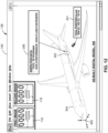
- Figure 12 shows a display screen 140 of a GUI 138 displaying a first image 116 and a second image 118 respectively of a portion of an aircraft 304 barrel section 308 captured by a first camera 106 and a second camera 108 of a 3D scanner 204 (e.g., Figure 6 ) into which the tool positioning system 100 is integrated. Also shown on the display screen 140 is the as-built digital model 160 of the aircraft 304 annotated with the tool position 201 (e.g., in x,y,z coordinates) of the 3D scanner 204 relative to the barrel section 308, and the inspection data 206 generated by the 3D scanner 204. In addition, the boundaries of the local region 302 inspected by the 3D scanner 204 can be highlighted on the as-built digital model 160 as shown in Figure 12 .
- the tool position 201 e.g., in x,y,z coordinates
- the inspection data 206 includes details regarding the type of inspection instrument 202 (e.g., 3D scanner) and the type of non-conformance (e.g., missing fasteners). However, the inspection data 206 can include any type of non-conformance, and is not limited to missing fasteners.
- the inspection data 206 can include alternative or additional information such as the date and time of the inspection, the geographical location where the inspection was performed, and other detailed information associated with the inspection.
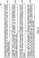
- FIG. 13 shown is an example of a method 500 of establishing the position of a tool 200 relative to a structure 300.
- the method 500 is described in the context of an aircraft 304 as described above and shown in Figure 1 .
- the method 500 is applicable for establishing the position of a tool 200 relative to any one of a variety of different types of structures 300, and is not limited to an aircraft 304.
- the method 500 is described in the context of establishing the position of a tool 200 in the form of a 3D scanner 204, the method 500 can be implemented for establishing the position of any one of a variety of different types of tools 200.
- Step 502 of the method 500 includes capturing, using two or more cameras 102 includable with the tool 200, images 114 of a local region 302 of the structure 300 respectively from two or more viewing perspectives.
- the cameras 102 are part of a tool positioning system 100 that includes a processor 130 for processing the images 114 captured by the cameras 102.
- the cameras 102 each have a unique viewing direction 110, which points generally toward a common local region 302 of the structure 300.
- the local region 302 is part of the structure 300 that is scanned by the 3D scanner 204.
- step 502 comprises capturing images 114 of the local region 302 using at least one standalone camera 120 mounted on the tool 200 as a separate component from the tool 200.
- Figures 1-5 show a first camera 106 and a second camera 108 as standalone cameras 120 mounted on the 3D scanner 204.
- the cameras 102 are spaced apart from the tool 200 by an offset distance 124.
- the method 500 includes compensating for the offset distance 124 when establishing the position of the tool 200 relative to the structure 300.
- step 502 comprises capturing images 114 of the local region 302 using at least one tool camera 208 that is integrated into the tool 200.
- Figures 6-10 show a first camera 106 and a second camera 108 as part of the 3D scanner 204 and which are therefore configured to perform the dual functions of scanning the structure 300 to generate a digital reconstruction of the scanned surfaces, and determining the position of the 3D scanner 204 relative to the structure 300 during the scanning operation.
- step 502 comprises capturing images 114 of the local region 302 using cameras 102 of a stationary tool 210 that is mounted to or supported on a fixed object.
- Figures 1-5 show a stationary tool 210 supported on a floor 216 of a manufacturing facility via a tool support fixture 212.
- Figures 6-7 show a stationary tool 210 mounted on a tripod 214 which is supported on a floor 216.
- the stationary tool 210 can be supported by any one of a variety of other types of fixed objects, and is not limited to supporting the tool 200 on a floor 216.
- step 502 comprises capturing images 114 of the local region 302 using cameras 102 included with a non-stationary tool 218 that is coupled to a movable platform 220.
- a non-stationary tool 218 e.g., a 3D scanner
- a drone 222 which is configured to hold the non-stationary tool 218 in three-dimensional space while the tool cameras 208 capture images 114 of the common local region 302 of the structure 300, and while scanning the surfaces of the structure 300 for assessing the condition of the structure 300 for the purpose of generating a digital reconstruction of the surfaces of structure 300 for inspection purposes.
- Step 504 of the method 500 includes comparing, using the processor 130, the images 114 to an as-designed digital model 150 of the structure 300 and recognizing one or more structural features 320 present in every image 114.
- the as-designed digital model 150 includes structural features 320 that make up the structure 300.
- the barrel section 308 of Figures 1-2 contains structural features 320 in the form of fasteners 326 ( Figures 2 , 4 and 5 ) and various structural components 332 such as window surrounds 324 (e.g., Figures 2 and 5 ), section joins 310 ( Figure 2 ), and any one of a variety of other structural components 332.
- the one or more structural features 320 used by the processor 130 in step 504 collectively include at least three unique elements 336 respectively at different locations on the structure 300, such as three or more fasteners 326 of a non-standard pattern 330 of fasteners 326 as shown in Figure 5 .
- the process of recognizing one or more structural features 320 in the images 114 can be performed using a suitable object recognition technique such as image analysis or machine learning.
- a suitable object recognition technique such as image analysis or machine learning.
- image analysis for recognizing structural features 320 in step 504 comprises using an edge detection algorithm such as the Canny edge detector algorithm or other suitable edge detection technique.
- machine learning to recognize structural features 320 in the images 114 comprises using convolutional neural networks such as MobileNetV3 TM .
- step 504 can be performed using any one of a variety of suitable techniques, and is not limited to image analysis or machine learning.
- Step 506 of the method 500 includes extracting, using the processor 130, the nominal three-dimensional location of the one or more structural features 320 from the as-designed digital model 150.
- the nominal three-dimensional locations of each structural feature 320 can be provided in terms of their local coordinates (e.g., x,y,z coordinates) relative to the origin of the global coordinate system 400.
- the processor 130 can query the as-built digital model 160 to extract the x,y,z coordinates of each one of three or more fasteners 326 of a non-standard pattern 330 of fasteners 326 as shown in the example of Figure 5 .
- Step 508 of the method 500 includes defining, using the processor 130, a geometric relationship between the cameras 102 and the structure 300 based on the nominal three-dimensional location(s) of the one or more structural features 320 to thereby establish the position of the tool 200 relative to the structure 300.
- the processor 130 uses triangulation to compute the geometric relationship between each camera 102 and the structure 300 based on the parameters (e.g., focal length, etc.) of the cameras 102.
- the processor 130 computes the respective position of each camera 102 relative to the structure 300.
- the collective position of the cameras 102 is defined in terms of the position of a local coordinate system 402 having an origin geometrically centered between the cameras 102.
- the origin of the local coordinate system 402 is located midway between the lens 104 of the first camera 106 and the lens 104 of the second camera 108.
- the method 500 includes annotating an as-built digital model 160 of the structure 300 with the position of the tool 200 relative to the structure 300.
- shown in Figure 12 is a display screen 140 of a computing device 134 displaying an as-built digital model 160 of the aircraft 304 of Figure 1 .
- the as-built digital model 160 has been annotated with the x,y,z coordinates of a 3D scanner 204 (i.e., the tool 200) relative to a barrel section 308 (i.e., the structure 300).
- the method 500 further includes annotating the as-built digital model 160 with inspection data 206 generated by an inspection instrument 202 after inspecting the structure 300.
- Figure 12 shows the as-built digital model 160 of the aircraft 304 annotated with inspection data 206 comprising the type of inspection instrument 202 (e.g., 3D scanner 204) and the type of non-conformance (e.g., missing fasteners) detected as a result of analyzing the inspection data 206.
- the method 500 can include displaying at least one of the following on a display screen 140 of a GUI 138: images 114 captured by the cameras 102, the as-designed digital model 150 of the structure 300, the structural feature 320 identified in the images 114, the position of the tool 200 relative to the structure 300, and/or the as-built digital model 160 of at least the local region 302 of the structure 300.
Landscapes
- Engineering & Computer Science (AREA)
- Physics & Mathematics (AREA)
- General Physics & Mathematics (AREA)
- Theoretical Computer Science (AREA)
- Signal Processing (AREA)
- Multimedia (AREA)
- Computer Vision & Pattern Recognition (AREA)
- Software Systems (AREA)
- General Engineering & Computer Science (AREA)
- Computer Hardware Design (AREA)
- Computer Graphics (AREA)
- Radar, Positioning & Navigation (AREA)
- Remote Sensing (AREA)
- Electromagnetism (AREA)
- Optics & Photonics (AREA)
- Mechanical Engineering (AREA)
- Length Measuring Devices By Optical Means (AREA)
Abstract
A tool positioning system comprises a processor and two or more cameras. The cameras are includable with a tool that is spaced apart from a structure. Each camera is configured to capture an image of a local region of the structure from a unique viewing perspective. The processor compares the images to an as-designed digital model of the structure and recognize one or more structural features that appear in every image. In addition, the processor extracts a nominal three-dimensional location of the one or more structural features from the as-designed digital model, and define a geometric relationship between the cameras and the structure based on the nominal three-dimensional location of the one or more structural features, to thereby establish the position of the tool relative to the structure.
Description
- The present disclosure relates generally to inspection systems and, more particularly, to a system and method for establishing the position of a tool, such as an inspection instrument, relative to a structure.
- Within the commercial aircraft industry, inspections are an essential part of the production process and ongoing maintenance for ensuring the quality and safety of the aircraft. One inspection technique involves the use of a three-dimensional (3D) scanner configured to scan the aircraft and generate a 3D digital representation of the scanned surfaces. The digital representation is highly accurate, allowing for the detection of non-conformances in the scanned surfaces. It is important to know the position of the 3D scanner relative to the aircraft so that if a non-conformance is discovered during analysis of the digital representation, the non-conformance can be located on the aircraft and corrected.
- Conventional methods for determining the position of an inspection instrument relative to a structure require the manual installation of physical markers or targets on regions of the structure to be inspected. For structures that are large in size, it can be difficult to access certain regions to apply physical targets, such as the vertical tail of a large commercial aircraft. For structures that have a large amount of surface area, manually applying physical targets to multiple regions of the structure is impractical.
- As can be seen, there exists a need in the art for a system and method for establishing the position of a tool (e.g., an inspection instrument) relative to a structure without the need to install physical targets on the structure.
- The above-noted needs associated with inspection systems are addressed by the present disclosure, which provides a tool positioning system for establishing the position of a tool relative to a structure. The tool positioning system includes two or more cameras that are includable with the tool. Each camera is configured to capture an image of a local region of the structure from a unique viewing perspective. The tool positioning system also includes a processor configured to compare the images to an as-designed digital model of the structure and recognize one or more structural features that appear in the images. In addition, the processor is configured to extract a nominal three-dimensional location of the one or more structural features from the as-designed digital model. Additionally, the processor is configured to define a geometric relationship between the cameras and the structure based on the nominal three-dimensional location of the one or more structural features, to thereby establish the position of the tool relative to the structure.
- Also disclosed is an inspection instrument having a processor and two cameras. The two cameras are each configured to capture at least one image of a structure respectively from a unique viewing perspective. The processor is configured to generate inspection data of the structure based on the images. In addition, the processor is configured to compare the images to an as-designed digital model of the structure and recognize one or more structural features present in every image, extract a nominal three-dimensional location of the one or more structural features from the as-designed digital model, and define a geometric relationship between the cameras and the structure based on the nominal three-dimensional location of the one or more structural features, to thereby establish the position of the inspection instrument relative to the structure at time of generating the inspection data.
- The features, functions, and advantages that have been discussed can be achieved independently in various versions of the disclosure or may be combined in yet other versions, further details of which can be seen with reference to the following description and drawings.
- The disclosure can be better understood with reference to the following detailed description taken in conjunction with the accompanying drawings, which illustrate preferred and exemplary versions, but which are not necessarily drawn to scale. The drawings are examples and not meant as limitations on the description or the claims.
-
Figure 1 shows an example of an aircraft having a fuselage comprised of end-to-end barrel sections; -
Figure 2 shows an example of one of the barrel sections ofFigure 1 , and illustrating the presently disclosed tool positioning system mounted on top of an inspection instrument in the form of a three-dimensional (3D) scanner for scanning a local region of the barrel section; -
Figure 3 is an end view of the barrel section ofFigure 2 showing the tool positioning system mounted on the 3D scanner; -
Figure 4 is a top view of the barrel section ofFigure 3 showing the tool positioning system having two cameras (e.g., a first camera and a second camera) mounted on the 3D scanner for capturing images of a local region of the barrel section from different viewing perspectives; -
Figure 5 is a magnified view of a portion of the barrel section showing the first and second cameras of the tool positioning system mounted on the 3D scanner which is supported on a tool support fixture, and further illustrating an overlap of the field of view of the first camera with the field of view of the second camera to define the local region on the barrel section; -
Figure 6 is an end view of an example of the tool positioning system in which the first and second cameras are integrated into a 3D scanner that is supported on a tripod; -
Figure 7 is a top view of the tool positioning system integrated into the 3D scanner ofFigure 6 ; -
Figure 8 is an end view of an example of the tool positioning system integrated into a 3D scanner that is supported by a drone; -
Figure 9 is a top view of the tool positioning system integrated into 3D scanner supported ofFigure 8 ; -
Figure 10 is an end view of the tool positioning system integrated into a 3D scanner that is supported by a robotic device; -
Figure 11 is a block diagram representing examples of the presently disclosed tool positioning system; -
Figure 12 shows an example of a display screen of a graphic user interface (GUI) displaying first and second images respectively captured by the first and second cameras of the tool positioning system ofFigure 5 , and illustrating an as-built digital model of the aircraft annotated with the tool position and inspection data generated by the tool (e.g., an inspection instrument); and -
Figure 13 is a flowchart of operations included in a method of establishing the position of a tool relative to a structure. - The figures shown in this disclosure represent various aspects of the versions presented, and only differences will be discussed in detail.
- Disclosed versions will now be described more fully hereinafter with reference to the accompanying drawings, in which some, but not all of the disclosed versions are shown. Indeed, several different versions may be provided and should not be construed as limited to the versions set forth herein. Rather, these versions are provided so that this disclosure will be thorough and fully convey the scope of the disclosure to those skilled in the art.
- This specification includes references to "one example," "an example," and "some examples." Instances of the phrases "one example," "an example," or "some examples" do not necessarily refer to the same example. Particular features, structures, or characteristics may be combined in any suitable manner consistent with this disclosure.
- As used herein, "comprising" is an open-ended term, and as used in the claims, this term does not foreclose additional structures or steps.
- As used herein, "configured to" means various parts or components may be described or claimed as "configured to" perform a task or tasks. In such contexts, "configured to" is used to connote structure by indicating that the parts or components include structure that performs those task or tasks during operation. As such, the parts or components can be said to be configured to perform the task even when the specified part or component is not currently operational (e.g., is not on).
- As used herein, an element or step recited in the singular and preceded by the word "a" or "an" should be understood as not necessarily excluding the plural of the elements or steps. As used herein, the term "and/or" includes any and all combinations of one or more of the associated listed items. As also used herein, the term "combinations thereof' includes combinations having at least one of the associated listed items, wherein the combination can further include additional, like non-listed items.
- As used herein, the phrase "at least one of," when used with a list of items, means different combinations of one or more of the listed items may be used, and only one of each item in the list may be needed. In other words, "at least one of' means any combination of items and number of items may be used from the list, but not all of the items in the list are required. The item may be a particular object, a thing, or a category.
- Referring now to the drawings which illustrate various examples of the disclosure, shown in
Figure 1 is anaircraft 304, which serves as an example for which the presently disclosed tool positioning system 100 (Figure 2 ) and method 500 (Figure 13 ) are used for determining or establishing the position of atool 200 relative to astructure 300. Theaircraft 304 includes afuselage 306, a pair ofwings 312, and an empennage containingtail surfaces 314 such as horizontal elevator and a vertical fin. In the example shown, thefuselage 306 is comprised of separately manufacturedbarrel sections 308 which are subsequently joined end-to-end at a plurality of section joins 310, as illustrated inFigures 1-2 . - In the example of
Figure 2 , thebarrel section 308 has a generally cylindrical shape having rows ofpassenger windows 322 on opposing sides of thebarrel section 308. Thewindows 322 each have awindow surround 324 providing local strength reinforcement around the window openings in thebarrel section 308. In some examples, thebarrel section 308 is of metallic construction and the exterior surface is defined by skin panels that are coupled viafasteners 326 to internal structural members such as longerons (not shown) and circumferential frames (not shown). - Although described in the context of an
aircraft 304, thetool positioning system 100 can be implemented for establishing the position of atool 200 relative to any one of a variety of different types ofstructures 300, and is not limited to anaircraft 304. Thestructure 300 can be of metallic construction (e.g., aluminum, etc.) and/or non-metallic construction (e.g., carbon-fiber composite material). Furthermore, although thetool 200 in the present disclosure is an inspection instrument 202 (e.g., a three-dimensional (3D) scanner), thetool positioning system 100 can be implemented for establishing the position of any one of a variety of different types oftools 200 including, but not limited to, manufacturing tools, testing tools, measuring tools, maintenance tools, and any other type of tool. Thetool 200 can be provided in any one of a variety of different forms, and is not limited to an instrument. For example, thetool 200 can be a device, a component, a machine, an assembly, a subassembly, a system, or a subsystem. - Referring to
Figures 1-5 , thetool positioning system 100 includes at least twocameras 102 and a processor 130 (Figure 5 ). Thecameras 102 are includable with thetool 200, and are configured to capture images 114 (Figure 5 ) of a commonlocal region 302 of thestructure 300 from different viewing perspectives. As described in greater detail below, theprocessor 130 is configured to compare theimages 114 of thelocal region 302 to an as-designed digital model 150 (Figure 11 ) of thestructure 300, and recognize one or morestructural features 320 that are part of thestructure 300, and which also appear in each of theimages 114. As described below, the one or morestructural features 320 that appear in the images 114 (e.g., afirst image 116 and a second image 118) collectively include at least three unique elements 336 (Figure 5 ). Theprocessor 130 is configured to extract the nominal three-dimensional location(s) of the one or morestructural features 320 from the as-designeddigital model 150, and define a geometric relationship between thecameras 102 and thestructure 300 based on the nominal three-dimensional location(s) of the one or morestructural features 320, to thereby establish the position of thetool 200 relative to thestructure 300, as described below. Advantageously, thetool positioning system 100 omits the need for manually installed reference targets to determine the position of thetool 200 relative to thestructure 300. - The cameras 102 (e.g., a
first camera 106 and a second camera 108) of thetool positioning system 100 each have a unique viewing direction 110 (Figure 4 ), and eachviewing direction 110 points generally toward the commonlocal region 302 of thestructure 300. In addition, thecameras 102 are oriented such that their fields ofview 112 at least partially overlap. For example, inFigure 4 , the field ofview 112 of thefirst camera 106 overlaps the field ofview 112 of thesecond camera 108, thereby providing stereo vision of thelocal region 302. Thelocal region 302 is defined by the overlapping portions of the fields ofview 112 of thecameras 102. Thefirst camera 106 andsecond camera 108 are spaced apart from each other. In addition, thefirst camera 106 andsecond camera 108 are oriented such that theviewing directions 110 form a slight angle which can range from 1-45 degrees or more. In addition, eachcamera 102 is preferably oriented such that itsviewing direction 110 is non-normal to the surfaces of thelocal region 302. In one example, thecameras 102 are oriented such that theviewing direction 110 of eachcamera 102 forms an angle of between 1-45 degrees relative to a local normal to the surface of thelocal region 302. However, theviewing direction 110 of eachcamera 102 can be oriented at any angle relative to a local normal of thelocal region 302. In the present disclosure, theviewing direction 110 of eachcamera 102 is generally centered within its field ofview 112. - Although the
tool positioning system 100 is described in the present disclosure as having two cameras 102 (e.g., afirst camera 106 and a second camera 108), other examples of thetool positioning system 100 can have more than twocameras 102 mounted on or adjacent to atool 200. For example, atool positioning system 100 can have three ormore cameras 102, each having adifferent viewing direction 110 respectively providing three or more unique viewing perspectives of a commonlocal region 302 of astructure 300. - In
Figures 1-5 , thecameras 102 of thetool positioning system 100 arestandalone cameras 120 that are separate components from thetool 200. Thestandalone cameras 120 can be temporarily or permanently mounted on or adjacent to thetool 200. Theprocessor 130 is configured to compensate for an offset distance 124 (Figure 3 ) between thestandalone cameras 120 and thetool 200 when establishing the position of thetool 200 relative to thestructure 300. Thestandalone cameras 120 are mounted or oriented in a manner such that eachcamera 102 has a unique viewing perspective of thelocal region 302 of thestructure 300. InFigures 1-5 , thestandalone cameras 120 are mounted on acamera mounting fixture 122 having mounting legs for supporting thestandalone cameras 120 on thetool 200. Although not shown, eachstandalone camera 120 can be mounted on a swivel (not shown) for independently adjusting the orientation of eachstandalone camera 120 in a manner such that the fields ofview 112 of thestandalone cameras 120 at least partially overlap each other on thestructure 300. - Referring to
Figures 6-10 , shown is an example of thetool positioning system 100 in which thecameras 102 aretool cameras 208 that are integrated or built into thetool 200. In addition to performing operations associated with the main purpose of thetool 200,tool cameras 208 are also configured to capture images 114 (Figure 12 ) of astructure 300 for establishing the position of thetool 200 relative to thestructure 300. For example, thetool 200 inFigures 6-10 is aninspection instrument 202 in the form of a3D scanner 204 containing twotool cameras 208. In this example, thetool cameras 208 are configured to perform dual functions, including (1) capturingimages 114 of alocal region 302 of astructure 300 from unique viewing perspectives for the purpose of establishing the position of the3D scanner 204 relative to thestructure 300, and (2) scanning the exterior surfaces of thestructure 300 for the purpose of generating a digital reconstruction of thestructure 300 to allow the condition of thestructure 300 to be assessed, such as inspecting thestructure 300 for non-conformances. - Although
Figures 1-5 show eachcamera 102 as astandalone camera 120 andFigures 6-10 show eachcamera 102 as atool camera 208, in other examples of thetool positioning system 100 not shown, one or more of thecameras 102 can be astandalone camera 120, and the remaining one ormore cameras 102 can be atool camera 208. Regardless of whether thecameras 102 of thetool positioning system 100 arestandalone cameras 120 and/ortool cameras 208, thecameras 102 of thetool positioning system 100 can be provided in any one of a variety of configurations. For example, thecameras 102 can be wide angle cameras machine vision cameras, and/or any one of a variety of other types of cameras capable of capturingimages 114 of astructure 300 for establishing the position of thetool 200 relative to thestructure 300. - In the example of
Figure 5 , thetool positioning system 100 includes a graphical user interface (GUI 138) which is part of acomputing device 134. In the example shown, thecomputing device 134 is alaptop computer 136. However, thecomputing device 134 can be a desktop computer (not shown), a tablet (not shown), or any other type ofcomputing device 134. Thecomputing device 134 contains theprocessor 130, which is communicatively coupled to thecameras 102. TheGUI 138 allows for manual control of the operation of thetool positioning system 100. For example, theGUI 138 allows for manually commanding thecameras 102 to captureimages 114 of thestructure 300. TheGLTI 138 of thelaptop computer 136 includes adisplay screen 140 which can display the images 114 (e.g., in real time) captured by thecameras 102. In addition, thedisplay screen 140 can display the as-designeddigital model 150 of thestructure 300, thestructural feature 320 identified in theimages 114, the position of thetool 200 relative to thestructure 300, and/or an as-builtdigital model 160 of at least a portion (e.g., the local region 302) of thestructure 300, as shown inFigure 12 and described below. - The
tool 200 can be astationary tool 210 or anon-stationary tool 218. In the example ofFigures 1-7 , thetool 200 is astationary tool 210 mounted to a fixed object. In this regard, thestationary tool 210 is fixed in location relative to thestructure 300. InFigures 1-5 , thestationary tool 210 is mounted on atool support fixture 212 which is supported on afloor 216 such as of a manufacturing facility. However, thestationary tool 210 can be fixedly coupled to a wall, a ceiling, or other type of fixed object. Furthermore, the fixed object can be located in any one of a variety of different types of environments, such as a factory, a maintenance facility, a hangar, or other environments. In addition, the fixed object can be located indoors or outdoors.Figures 6-7 show an example of astationary tool 210 mounted on atripod 214 which is supported on afloor 216. Thestationary tool 210 is aninspection instrument 202 in the form of the above-mentioned3D scanner 204. In this example, the cameras 102 (e.g., thefirst camera 106 and the second camera 108) of thetool positioning system 100 aretool cameras 208 that are integrated into the3D scanner 204. - Referring to
Figures 8-10 , shown are examples of atool positioning system 100 in which thetool 200 is anon-stationary tool 218 coupled to amovable platform 220. InFigures 8-9 , themovable platform 220 is a remotely commanded (e.g., via a human) or autonomously commanded (i.e., preprogrammed) aerial vehicle ordrone 222 having multiple propellers for supporting thetool 200 which, in the example shown, is a3D scanner 204. Thedrone 222 is configured to hold the3D scanner 204 in three-dimensional space while thetool cameras 208 of the3D scanner 204 perform the above-mentioned dual functions of capturingimages 114 of a commonlocal region 302 of thestructure 300 for establishing the position of the3D scanner 204, and scanning the surfaces of thestructure 300 for assessing (i.e., inspecting) the condition of thestructure 300. InFigure 10 , themovable platform 220 is arobotic device 224 havingrobotic arms 226 and a base (not shown) that is movable along a robotic device track (not shown) for positioning thetool 200 at any location along astructure 300. Thetool 200 inFigure 10 is a3D scanner 204 havingtool cameras 208 configured to perform the same dual functions described above for the3D scanner 204 ofFigures 8-9 . Although themovable platform 220 is shown in the present disclosure as adrone 222 or arobotic device 224, themovable platform 220 may be provided in any one of a variety of alternative configurations such as an overhead gantry (not shown) or other type ofmovable platform 220. - As mentioned above, the presently disclosed
tool positioning system 100 is described in the context of establishing the position of atool 200 in the form of aninspection instrument 202 such as a3D scanner 204. In one example, the3D scanner 204 is a structured light scanner such as the ATOS line of scanners commercially available from the Zeiss Group of Oberkochen, Germany. However, thetool positioning system 100 can be implemented for establishing the position of any one of a variety of alternative types ofinspection instruments 202. For example, theinspection instrument 202 can be a laser scanner, a time-of-flight scanner, or any one of a variety of other types ofinspection instruments 202 for performing any one of a variety of different types of inspection or metrology activities. For example, thetool 200 can be aninspection instrument 202 configured to perform surface inspections to detect non-conformances such as corrosion in metallic components, oversized gaps between structural components, wear and tear on surface coatings such as paint, and/or defects in fastener installations such as missing fasteners or non-flush countersunk fasteners. In some examples, thetool 200 can be aninspection instrument 202 configured to perform composite material inspections for detecting non-conformances such as voids, delaminations, and/or cracks in composite structures. - Referring to
Figure 11 , shown is a block diagram representing examples of the presently disclosedtool positioning system 100. As mentioned above, theprocessor 130 is configured to receive the images 114 (Figure 5 ) of thelocal region 302 captured by thecameras 102. Using photogrammetry, theprocessor 130 compares theimages 114 of thelocal region 302 to an as-designed digital model 150 (e.g., a computer-aided-design (CAD) model) of thestructure 300. InFigure 11 , the as-designeddigital model 150 is stored in amemory 132 that is communicatively coupled to or integrated into theprocessor 130. Theprocessor 130 and thememory 132 can be integrated into acomputing device 134, as mentioned above. The as-designeddigital model 150 represents at least the portion of thestructure 300 containing thelocal region 302. For the example ofFigure 2 , the as-designeddigital model 150 is that of abarrel section 308. In other examples, the as-designeddigital model 150 can be that of theentire structure 300, such as theentire aircraft 304 ofFigure 1 . - Included in the as-designed
digital model 150 arestructural features 320 that make up thestructure 300. In this regard, thestructural features 320 are integral to thestructure 300 and are not applied to thestructure 300 solely for the purpose of determining the position of atool 200 relative to thestructure 300. In the example of thebarrel section 308 ofFigures 1-2 ,structural features 320 can include the fasteners 326 (Figures 2 ,4 and5 ), variousstructural components 332 that make up thebarrel section 308, and can also include non-structural components (not shown) of thebarrel section 308. Examples ofstructural components 332 of thebarrel section 308 include window surrounds 324 (e.g.,Figures 2 and5 ), section joins 310 (Figure 2 ), and any one of a variety of otherstructural components 332 that are part of the as-designeddigital model 150, and which can be captured in theimages 114 generated by thecameras 102 of thetool positioning system 100. - The
processor 130 is configured to recognize one or morestructural features 320 that appear in theimages 114 based on a comparison of theimages 114 to the as-designeddigital model 150. Recognition of thestructural features 320 in theimages 114 can be performed using a suitable object recognition technique such as image analysis, machine learning, or any other suitable object recognition technique. As mentioned above, the one or morestructural features 320 collectively include at least threeunique elements 336 respectively at different locations on thestructure 300. In one example, theunique elements 336 can be comprised of three ormore fasteners 326 in a non-repeating and/ornon-standard pattern 330 offasteners 326. For example,Figure 5 shows anon-standard pattern 330 offasteners 326 located near the approximate mid-point of thebarrel section 308 underneath the row ofwindows 322. Thenon-standard pattern 330 offasteners 326 is in addition to thestandard pattern 328 offasteners 326 that extend in lengthwise rows along the entire length of thebarrel section 308 for coupling the skin panels to internal longerons (not shown) that extend the length of thebarrel section 308, and the circumferential rows offasteners 326 that fasten the skin panels to internal circumferential frames (not shown) of thebarrel section 308. - As an alternative to or in addition to
fasteners 326, the at least threeunique elements 336 of the one or morestructural features 320 can be comprised of three or more different corners oredges 334 of a singlestructural component 332. For example, inFigure 5 , the three or moreunique elements 336 can be respectively comprised of three or moredifferent edges 334 or sides of one of the window surrounds 324, or three ormore edges 334 or corners of one of the section joins 310. Other examples ofstructural components 332 that can serve as astructural features 320 include inspection access doors (not shown), door surrounds (not shown) of passenger doors or cargo doors, edges 334 of skin panels such as of awing 312, afuselage 306, or a control surface (no shown), or any one of a variety of other types ofstructural components 332. - Upon recognizing one or more
structural features 320 that appear in theimages 114 of thelocal region 302 captured by thecameras 102, theprocessor 130 extracts the nominal three-dimensional location(s) of the one or morestructural features 320 by querying the as-designeddigital model 150. The nominal three-dimensional location(s) of the one or morestructural features 320 can be provided in terms of their local coordinates (e.g., x,y,z coordinates) relative to the origin of the global coordinatesystem 400 of thestructure 300. - The
processor 130 defines a geometric relationship between thecameras 102 and thestructure 300 based on the nominal three-dimensional location(s) of the one or morestructural features 320 extracted from the as-designeddigital model 150. In this regard, theprocessor 130 uses triangulation to compute the respective positions of eachcamera 102 relative to thestructure 300 based on the parameters (e.g., focal length, etc.) of thecameras 102. In the example of thetool positioning system 100 ofFigures 2-10 which has exactly two cameras 102 (i.e., afirst camera 106 and a second camera 108), the location of both thefirst camera 106 and thesecond cameras 102 is collectively represented by a local coordinatesystem 402 with origin located midway between thelens 104 of thefirst camera 106 and thelens 104 of thesecond camera 108. - In addition to determining the position of the
cameras 102 relative to thestructure 300, the above-noted process determines the orientation of thecameras 102 relative to thestructure 300 based on theviewing directions 110 of thecameras 102. The orientation of thecameras 102 can be defined in terms of the orientation of the local coordinate system 402 (Figure 2 ) of thecameras 102 relative to the global coordinate system 400 (Figure 2 ) of thestructure 300. In the present disclosure, the orientation of thecameras 102 is defined by the x-axis and y-axis of the local coordinatesystem 402 which is in the plane defined by theviewing directions 110 of thefirst camera 106 and thesecond camera 108, with the y-axis bisecting the angle between theviewing directions 110, as shown inFigure 4 . - In any of the examples disclosed herein, the
processor 130 requires three or moreunique elements 336 to allow the algorithm to converge on a single solution for the three-dimensional position of thetool 200 relative to thestructure 300. If theunique elements 336 are not unique enough relative to other parts of thestructure 300, theprocessor 130 may generate multiple solutions for the three-dimensional position of thetool 200. If multiple solutions are generated, then human intervention is implemented to select the appropriate position of thetool 200 from among the multiple solutions. - For examples of the
tool positioning system 100 in which thecameras 102 arestandalone cameras 120 as shown inFigures 1-5 , theprocessor 130 compensates for the offset distance 124 (Figure 3 ) between thestandalone cameras 120 and thetool 200 to thereby establish the position of thetool 200 relative to thestructure 300, as mentioned above. For examples of thetool positioning system 100 in which thecameras 102 aretool cameras 208 that are integrated into thetool 200 as shown inFigures 6-10 , the position of thetool 200 is the position of thecameras 102. - Referring still to
Figure 11 , thetool 200 can be an inspection instrument 202 (e.g., a 3D scanner) for inspecting the surfaces of astructure 300, as mentioned above. Theinspection instrument 202 generatesinspection data 206 documenting the results of an inspection. Theinspection data 206 can include non-conformances in thestructure 300 that are detected by theinspection instrument 202. Examples of non-conformances can include: corrosion of a metallic component, degradation of a surface coating, defects in fastener installations, and any one of a variety of other types of non-conformances. Theprocessor 130 is configured to record (e.g., in the memory 132) theinspection data 206 and the position of thetool 200 relative to the structure 300 (i.e., the tool position 201 -Figure 11 ) at the time that thetool 200 generated theinspection data 206. - Referring to
Figures 11-12 , theprocessor 130 in some examples is configured to annotate a three-dimensional as-builtdigital model 160 of thestructure 300 with the position of thetool 200 relative to thestructure 300. In the present disclosure, the as-builtdigital model 160 is a digital representation of thephysical structure 300 as manufactured and as modified during its operational life, and can be referred to as a digital twin of thestructure 300. In this regard, the as-builtdigital model 160 can be continuously updated over time to reflect deviations and/or changes that have been made to thestructure 300 relative to the as-designeddigital model 150. - In some examples of the
tool positioning system 100, theprocessor 130 can facilitate the construction and/or updating of the as-builtdigital model 160. For example, if thetool positioning system 100 is integrated into a3D scanner 204 such as an ATOS scanner mentioned above, theprocessor 130 of the3D scanner 204 can perform the dual functions of (1) scanning the surfaces of thestructure 300 and generating a digital reconstruction of the scanned surfaces (e.g., of a local region 302) for inspection purposes, and (2) determining the position of the3D scanner 204 relative to thestructure 300 during the scanning operation. The reconstructed surface generated by the3D scanner 204 can be used to update the as-builtdigital model 160. In addition,inspection data 206 resulting from analysis of the reconstructed surface can be used to annotate the as-builtdigital model 160. - For example,
Figure 12 shows adisplay screen 140 of aGUI 138 displaying afirst image 116 and asecond image 118 respectively of a portion of anaircraft 304barrel section 308 captured by afirst camera 106 and asecond camera 108 of a 3D scanner 204 (e.g.,Figure 6 ) into which thetool positioning system 100 is integrated. Also shown on thedisplay screen 140 is the as-builtdigital model 160 of theaircraft 304 annotated with the tool position 201 (e.g., in x,y,z coordinates) of the3D scanner 204 relative to thebarrel section 308, and theinspection data 206 generated by the3D scanner 204. In addition, the boundaries of thelocal region 302 inspected by the3D scanner 204 can be highlighted on the as-builtdigital model 160 as shown inFigure 12 . - In
Figure 12 , theinspection data 206 includes details regarding the type of inspection instrument 202 (e.g., 3D scanner) and the type of non-conformance (e.g., missing fasteners). However, theinspection data 206 can include any type of non-conformance, and is not limited to missing fasteners. Theinspection data 206 can include alternative or additional information such as the date and time of the inspection, the geographical location where the inspection was performed, and other detailed information associated with the inspection. - Referring to
Figure 13 , shown is an example of amethod 500 of establishing the position of atool 200 relative to astructure 300. Themethod 500 is described in the context of anaircraft 304 as described above and shown inFigure 1 . However, themethod 500 is applicable for establishing the position of atool 200 relative to any one of a variety of different types ofstructures 300, and is not limited to anaircraft 304. In addition, although themethod 500 is described in the context of establishing the position of atool 200 in the form of a3D scanner 204, themethod 500 can be implemented for establishing the position of any one of a variety of different types oftools 200. - Step 502 of the
method 500 includes capturing, using two ormore cameras 102 includable with thetool 200,images 114 of alocal region 302 of thestructure 300 respectively from two or more viewing perspectives. As described above, thecameras 102 are part of atool positioning system 100 that includes aprocessor 130 for processing theimages 114 captured by thecameras 102. As mentioned above, thecameras 102 each have aunique viewing direction 110, which points generally toward a commonlocal region 302 of thestructure 300. In the example where thetool 200 is a3D scanner 204, thelocal region 302 is part of thestructure 300 that is scanned by the3D scanner 204. - In some examples of the
method 500, step 502 comprises capturingimages 114 of thelocal region 302 using at least onestandalone camera 120 mounted on thetool 200 as a separate component from thetool 200. For example,Figures 1-5 show afirst camera 106 and asecond camera 108 asstandalone cameras 120 mounted on the3D scanner 204. As shown inFigure 3 , thecameras 102 are spaced apart from thetool 200 by an offsetdistance 124. In such examples, themethod 500 includes compensating for the offsetdistance 124 when establishing the position of thetool 200 relative to thestructure 300. - In other examples of the
method 500, step 502 comprises capturingimages 114 of thelocal region 302 using at least onetool camera 208 that is integrated into thetool 200. For example,Figures 6-10 show afirst camera 106 and asecond camera 108 as part of the3D scanner 204 and which are therefore configured to perform the dual functions of scanning thestructure 300 to generate a digital reconstruction of the scanned surfaces, and determining the position of the3D scanner 204 relative to thestructure 300 during the scanning operation. - In some examples of the
method 500, step 502 comprises capturingimages 114 of thelocal region 302 usingcameras 102 of astationary tool 210 that is mounted to or supported on a fixed object. For example,Figures 1-5 show astationary tool 210 supported on afloor 216 of a manufacturing facility via atool support fixture 212.Figures 6-7 show astationary tool 210 mounted on atripod 214 which is supported on afloor 216. However, in other examples, thestationary tool 210 can be supported by any one of a variety of other types of fixed objects, and is not limited to supporting thetool 200 on afloor 216. - In still other examples, step 502 comprises capturing
images 114 of thelocal region 302 usingcameras 102 included with anon-stationary tool 218 that is coupled to amovable platform 220. For example,Figures 8-9 show a non-stationary tool 218 (e.g., a 3D scanner) supported by adrone 222 which is configured to hold thenon-stationary tool 218 in three-dimensional space while thetool cameras 208capture images 114 of the commonlocal region 302 of thestructure 300, and while scanning the surfaces of thestructure 300 for assessing the condition of thestructure 300 for the purpose of generating a digital reconstruction of the surfaces ofstructure 300 for inspection purposes. - Step 504 of the
method 500 includes comparing, using theprocessor 130, theimages 114 to an as-designeddigital model 150 of thestructure 300 and recognizing one or morestructural features 320 present in everyimage 114. As described above, the as-designeddigital model 150 includesstructural features 320 that make up thestructure 300. For example, thebarrel section 308 ofFigures 1-2 containsstructural features 320 in the form of fasteners 326 (Figures 2 ,4 and5 ) and variousstructural components 332 such as window surrounds 324 (e.g.,Figures 2 and5 ), section joins 310 (Figure 2 ), and any one of a variety of otherstructural components 332. Notably, as described above, the one or morestructural features 320 used by theprocessor 130 instep 504 collectively include at least threeunique elements 336 respectively at different locations on thestructure 300, such as three ormore fasteners 326 of anon-standard pattern 330 offasteners 326 as shown inFigure 5 . - The process of recognizing one or more
structural features 320 in theimages 114 can be performed using a suitable object recognition technique such as image analysis or machine learning. One example of using image analysis for recognizingstructural features 320 instep 504 comprises using an edge detection algorithm such as the Canny edge detector algorithm or other suitable edge detection technique. One example of using machine learning to recognizestructural features 320 in theimages 114 comprises using convolutional neural networks such as MobileNetV3™. However, step 504 can be performed using any one of a variety of suitable techniques, and is not limited to image analysis or machine learning. - Step 506 of the
method 500 includes extracting, using theprocessor 130, the nominal three-dimensional location of the one or morestructural features 320 from the as-designeddigital model 150. As described above, the nominal three-dimensional locations of eachstructural feature 320 can be provided in terms of their local coordinates (e.g., x,y,z coordinates) relative to the origin of the global coordinatesystem 400. For example, theprocessor 130 can query the as-builtdigital model 160 to extract the x,y,z coordinates of each one of three ormore fasteners 326 of anon-standard pattern 330 offasteners 326 as shown in the example ofFigure 5 . - Step 508 of the
method 500 includes defining, using theprocessor 130, a geometric relationship between thecameras 102 and thestructure 300 based on the nominal three-dimensional location(s) of the one or morestructural features 320 to thereby establish the position of thetool 200 relative to thestructure 300. As described above, theprocessor 130 uses triangulation to compute the geometric relationship between eachcamera 102 and thestructure 300 based on the parameters (e.g., focal length, etc.) of thecameras 102. In establishing the geometric relationship between thecameras 102 and thestructure 300, theprocessor 130 computes the respective position of eachcamera 102 relative to thestructure 300. The collective position of thecameras 102 is defined in terms of the position of a local coordinatesystem 402 having an origin geometrically centered between thecameras 102. For example, in thetool positioning system 100 ofFigures 2-10 which has afirst camera 106 and asecond camera 108, the origin of the local coordinatesystem 402 is located midway between thelens 104 of thefirst camera 106 and thelens 104 of thesecond camera 108. - In some examples, the
method 500 includes annotating an as-builtdigital model 160 of thestructure 300 with the position of thetool 200 relative to thestructure 300. For example, shown inFigure 12 is adisplay screen 140 of acomputing device 134 displaying an as-builtdigital model 160 of theaircraft 304 ofFigure 1 . The as-builtdigital model 160 has been annotated with the x,y,z coordinates of a 3D scanner 204 (i.e., the tool 200) relative to a barrel section 308 (i.e., the structure 300). In some examples, themethod 500 further includes annotating the as-builtdigital model 160 withinspection data 206 generated by aninspection instrument 202 after inspecting thestructure 300. For example,Figure 12 shows the as-builtdigital model 160 of theaircraft 304 annotated withinspection data 206 comprising the type of inspection instrument 202 (e.g., 3D scanner 204) and the type of non-conformance (e.g., missing fasteners) detected as a result of analyzing theinspection data 206. In this regard, themethod 500 can include displaying at least one of the following on adisplay screen 140 of a GUI 138:images 114 captured by thecameras 102, the as-designeddigital model 150 of thestructure 300, thestructural feature 320 identified in theimages 114, the position of thetool 200 relative to thestructure 300, and/or the as-builtdigital model 160 of at least thelocal region 302 of thestructure 300. - Further, the current disclosure comprises embodiments according to the following clauses:
- Clause 1. A tool positioning system for establishing the position of a tool relative to a structure, comprising:
- two or more cameras includable with the tool, and each camera is configured to capture an image of a local region of the structure from a unique viewing perspective;
- a processor configured to:
- compare the images to an as-designed digital model of the structure and recognize one or more structural features that appear in every image;
- extract a nominal three-dimensional location of the one or more structural features from the as-designed digital model; and
- define a geometric relationship between the cameras and the structure based on the nominal three-dimensional location of the one or more structural features, to thereby establish a position of the tool relative to the structure.
-
Clause 2. The tool positioning system of Clause 1, wherein:
at least one of the cameras is a standalone camera mountable on the tool as a separate component. - Clause 3. The tool positioning system of
Clause 2, wherein:
the processor is configured to compensate for an offset distance between the standalone camera and the tool when establishing the position of the tool relative to the structure. -
Clause 4. The tool positioning system of any of Clauses 1 to 3, wherein:
at least one of the cameras is a tool camera integrated into the tool. - Clause 5. The tool positioning system of any of Clauses 1 to 4, wherein:
the tool is a stationary tool mounted to a fixed object. - Clause 6. The tool positioning system of any of Clauses 1 to 5, wherein:
the tool is a non-stationary tool that is coupled to a movable platform. -
Clause 7. The tool positioning system of any of Clauses 1 to 6, wherein:
the processor is configured to annotate an as-built digital model of the structure with the position of the tool relative to the structure. - Clause 8. The tool positioning system of
Clause 7, wherein:
the tool is an inspection instrument configured to inspect the structure and generate inspection data; and the processor is configured to annotate the as-built digital model with the inspection data and the position of the inspection instrument relative to the structure at time of recording the inspection data. -
Clause 9. The tool positioning system of any of Clauses 1 to 8, further comprising a graphical user interface (GUI) configured to display at least one of the following:
the images captured by the cameras, the as-designed digital model of the structure, the structural feature identified in the images and its nominal three-dimensional location, the position of the tool relative to the structure, an as-built digital model of at least the local region of the structure. - Clause 10. An inspection instrument, comprising:
- two cameras, each configured to capture at least one image of a structure respectively from a unique viewing perspective;
- a processor configured to:
- generate inspection data of the structure based on the images;
- compare the images to an as-designed digital model of the structure and recognize one or more structural features present in every image;
- extract a nominal three-dimensional location of the one or more structural features from the as-designed digital model; and
- define a geometric relationship between the cameras and the structure based on the nominal three-dimensional location of the one or more structural features, to thereby establish a position of the inspection instrument relative to the structure at time of generating the inspection data.
- Clause 11. The inspection instrument of Clause 10, wherein:
the processor is configured to annotate an as-built digital model with the inspection data and the position of the inspection instrument relative to the structure at time of recording the inspection data. - Clause 12. A method of establishing the position of a tool relative to a structure, comprising: capturing, using two or more cameras includable with the tool, images of a local region of the structure respectively from two or more viewing perspectives;
- comparing, using a processor, the images to an as-designed digital model of the structure and recognizing one or more structural features present in every image;
- extracting, using the processor, a nominal three-dimensional location of the one or more structural features from the as-designed digital model; and
- defining, using the processor, a geometric relationship between the cameras and the structure based on the nominal three-dimensional location of the one or more structural features to thereby establish a position of the tool relative to the structure.
- Clause 13. The method of Clause 11, wherein capturing images of the local region comprises: capturing images of the local region using at least one standalone camera mounted on the tool as a separate component.
- Clause 14. The method of Clause 13, further comprising:
compensating for an offset distance between the standalone cameras and the tool when establishing the position of the tool relative to the structure. - Clause 15. The method of any of Clauses 12 to 14, wherein capturing images of the local region comprises:
capturing images of the local region using at least one tool camera that is integrated into the tool. - Clause 16. The method of any of Clauses 12 to 15, wherein capturing images of the local region comprises:
capturing images of the local region using cameras included with a stationary tool mounted to a fixed object. - Clause 17. The method of any of Clauses 12 to 16, wherein capturing images of the local region comprises:
capturing images of the local region using cameras included with a non-stationary tool that is coupled to a movable platform. - Clause 18. The method of any of Clauses 12 to 17, further comprising:
annotating an as-built digital model of the structure with the position of the tool relative to the structure. - Clause 19. The method of Clause 18, wherein annotating the as-built digital model of the structure with the position of the tool relative to the structure further comprises:
annotating the as-built digital model of the structure with inspection data generated by an inspection instrument after inspecting the structure. - Clause 20. The method of any of Clauses 12 to 19, further comprising:
displaying on a graphical user interface (GUI) at least one of the following: the images captured by the cameras, an as-designed digital model of the structure, the structural feature identified in the images, the position of the tool relative to the structure, an as-built digital model of at least the local region of the structure. - Many modifications and other versions and examples of the disclosure will come to mind to one skilled in the art to which this disclosure pertains having the benefit of the teachings presented in the foregoing descriptions and the associated drawings. The versions and examples described herein are meant to be illustrative and are not intended to be limiting or exhaustive. Although specific terms are employed herein, they are used in a generic and descriptive sense only and not for purposes of limitation. Functionally equivalent methods and apparatuses within the scope of the disclosure, in addition to those enumerated herein, are possible from the foregoing descriptions. Such modifications and variations are intended to fall within the scope of the appended claims. The present disclosure is to be limited only by the terms of the appended claims, along with the full scope of equivalents to which such claims are entitled.
Claims (15)
- A tool positioning system (100) for establishing a position of a tool (200) relative to a structure (300), comprising:two or more cameras (102) includable with the tool (200), and each camera (102) is configured to capture an image (114) of a local region (302) of the structure (300) from a unique viewing perspective;a processor (130) configured to:compare the images (114) to an as-designed digital model (150) of the structure (300) and recognize one or more structural features (320) that appear in every image (114);extract a nominal three-dimensional location of the one or more structural features (320) from the as-designed digital model (150); anddefine a geometric relationship between the cameras (102) and the structure (300) based on the nominal three-dimensional location of the one or more structural features (320), to thereby establish a position of the tool (200) relative to the structure (300).
- The tool positioning system (100) of Claim 1, wherein:
at least one of the cameras (102) is a standalone camera (120) mountable on the tool (200) as a separate component. - The tool positioning system (100) of Claim 2, wherein:
the processor (130) is configured to compensate for an offset distance (124) between the standalone camera (120) and the tool (200) when establishing the position of the tool (200) relative to the structure (300). - The tool positioning system (100) of Claim 1, wherein:
at least one of the cameras (102) is a tool camera (208) integrated into the tool (200). - The tool positioning system (100) of Claim 1, wherein:
the tool (200) is a stationary tool (210) mounted to a fixed object. - The tool positioning system (100) of Claim 1, wherein:
the tool (200) is a non-stationary tool (218) that is coupled to a movable platform (220). - The tool positioning system (100) of Claim 1, wherein:
the processor (130) is configured to annotate an as-built digital model (160) of the structure (300) with the position of the tool (200) relative to the structure (300). - The tool positioning system (100) of Claim 7, wherein:the tool (200) is an inspection instrument (202) configured to inspect the structure (300) and generate inspection data (206); andthe processor (130) is configured to annotate the as-built digital model (160) with the inspection data (206) and the position of the inspection instrument (202) relative to the structure (300) at time of recording the inspection data (206).
- The tool positioning system (100) of Claim 1, further comprising a graphical user interface (GLTI (138)) configured to display at least one of the following:
the images (114) captured by the cameras (102), the as-designed digital model (150) of the structure (300), the structural feature (320) identified in the images (114) and its nominal three-dimensional location, the position of the tool (200) relative to the structure (300), an as-built digital model (160) of at least the local region (302) of the structure (300). - An inspection instrument (202), comprising:two cameras (102), each configured to capture at least one image (114) of a structure (300) respectively from a unique viewing perspective;a processor (130) configured to:generate inspection data (206) of the structure (300) based on the images (114);compare the images (114) to an as-designed digital model (150) of the structure (300) and recognize one or more structural features (320) present in every image (114);extract a nominal three-dimensional location of the one or more structural features (320) from the as-designed digital model (150); anddefine a geometric relationship between the cameras (102) and the structure (300) based on the nominal three-dimensional location of the one or more structural features (320), to thereby establish a position of the inspection instrument (202) relative to the structure (300) at time of generating the inspection data (206).
- A method of establishing a position of a tool (200) relative to a structure (300), comprising:capturing, using two or more cameras (102) includable with the tool (200), images (114) of a local region (302) of the structure (300) respectively from two or more viewing perspectives;comparing, using a processor (130), the images (114) to an as-designed digital model (150) of the structure (300) and recognizing one or more structural features (320) present in every image (114);extracting, using the processor (130), a nominal three-dimensional location of the one or more structural features (320) from the as-designed digital model (150); anddefining, using the processor (130), a geometric relationship between the cameras (102) and the structure (300) based on the nominal three-dimensional location of the one or more structural features (320) to thereby establish a position of the tool (200) relative to the structure (300).
- The method of Claim 11, wherein capturing images (114) of the local region (302) comprises:
capturing images (114) of the local region (302) using at least one standalone camera (120) mounted on the tool (200) as a separate component. - The method of Claim 12, further comprising:
compensating for an offset distance (124) between the standalone cameras (120) and the tool (200) when establishing the position of the tool (200) relative to the structure (300). - The method of any of Claims 11 to 13, wherein capturing images (114) of the local region (302) comprises:
capturing images (114) of the local region (302) using at least one tool camera (208) that is integrated into the tool (200). - The method of any of Claims 12 to 14, wherein capturing images (114) of the local region (302) comprises:
capturing images (114) of the local region (302) using cameras (102) included with a stationary tool (210) mounted to a fixed object.
Applications Claiming Priority (1)
| Application Number | Priority Date | Filing Date | Title |
|---|---|---|---|
| US18/473,162 US20250104275A1 (en) | 2023-09-22 | 2023-09-22 | System and method for establishing the position of a tool relative to a structure |
Publications (1)
| Publication Number | Publication Date |
|---|---|
| EP4528213A1 true EP4528213A1 (en) | 2025-03-26 |
Family
ID=91782475
Family Applications (1)
| Application Number | Title | Priority Date | Filing Date |
|---|---|---|---|
| EP24186088.1A Pending EP4528213A1 (en) | 2023-09-22 | 2024-07-02 | System and method for establishing the position of a tool relative to a structure |
Country Status (2)
| Country | Link |
|---|---|
| US (1) | US20250104275A1 (en) |
| EP (1) | EP4528213A1 (en) |
Citations (3)
| Publication number | Priority date | Publication date | Assignee | Title |
|---|---|---|---|---|
| EP2703776B1 (en) * | 2012-08-27 | 2020-03-18 | The Boeing Company | Method and system for inspecting a workpiece |
| EP3208774B1 (en) * | 2016-02-19 | 2021-09-08 | The Boeing Company | Methods for localization using geotagged photographs and three-dimensional visualization |
| EP3549874B1 (en) * | 2018-04-04 | 2022-12-21 | The Boeing Company | Mobile visual-inspection system |
Family Cites Families (6)
| Publication number | Priority date | Publication date | Assignee | Title |
|---|---|---|---|---|
| US20130342657A1 (en) * | 2012-06-15 | 2013-12-26 | Nikon Corporation | Stereo vision camera for laser radar |
| US12446969B2 (en) * | 2019-05-20 | 2025-10-21 | Icahn School Of Medicine At Mount Sinai | Robot mounted camera registration and tracking system for orthopedic and neurological surgery |
| JP7415028B2 (en) * | 2020-09-28 | 2024-01-16 | ファナック株式会社 | Imaging condition adjustment device and imaging condition adjustment method |
| WO2023203726A1 (en) * | 2022-04-21 | 2023-10-26 | ヤマハ発動機株式会社 | Image acquisition device |
| EP4421709A1 (en) * | 2023-02-22 | 2024-08-28 | Siemens Aktiengesellschaft | Method of generating an industrial electrical product disassembly routine |
| US20240362985A1 (en) * | 2023-04-26 | 2024-10-31 | T-Mobile Usa, Inc. | System including wireless handheld mobile device configured for monitoring selected areas |
-
2023
- 2023-09-22 US US18/473,162 patent/US20250104275A1/en active Pending
-
2024
- 2024-07-02 EP EP24186088.1A patent/EP4528213A1/en active Pending
Patent Citations (3)
| Publication number | Priority date | Publication date | Assignee | Title |
|---|---|---|---|---|
| EP2703776B1 (en) * | 2012-08-27 | 2020-03-18 | The Boeing Company | Method and system for inspecting a workpiece |
| EP3208774B1 (en) * | 2016-02-19 | 2021-09-08 | The Boeing Company | Methods for localization using geotagged photographs and three-dimensional visualization |
| EP3549874B1 (en) * | 2018-04-04 | 2022-12-21 | The Boeing Company | Mobile visual-inspection system |
Also Published As
| Publication number | Publication date |
|---|---|
| US20250104275A1 (en) | 2025-03-27 |
Similar Documents
| Publication | Publication Date | Title |
|---|---|---|
| US10450053B2 (en) | Methods using predictive shimming to optimize part-to-part alignment | |
| EP2625105B1 (en) | Automated visual inspection system | |
| EP3270247B1 (en) | System and method for generating enhanced stereographic videos of aircraft build processes | |
| US9187188B2 (en) | Assembly inspection system and method | |
| JP7712201B2 (en) | Method and apparatus for measuring fastener concentricity - Patents.com | |
| CN112101130B (en) | Rivet forming quality detection and judgment system and method based on visual recognition technology | |
| Aldao et al. | Metrological comparison of LiDAR and photogrammetric systems for deformation monitoring of aerospace parts | |
| Rice et al. | Automating the visual inspection of aircraft | |
| US20120290243A1 (en) | Method for automated detection of individual parts of a complex differential structure | |
| Leiva et al. | Automatic visual detection and verification of exterior aircraft elements | |
| EP3833601A1 (en) | Method for detecting a door status of an aircraft door | |
| US20250104275A1 (en) | System and method for establishing the position of a tool relative to a structure | |
| US20240169515A1 (en) | Quality inspection of a vehicle body | |
| US20230362494A1 (en) | Photographic Strobe Inspection | |
| US11618591B2 (en) | Composite laminate damage detection method using an in-situ thermal gradient and expansion differences across the damage | |
| WO2016077653A1 (en) | Novel systems and methods for processing an object | |
| US20240383616A1 (en) | Systems and methods for inspecting aircraft | |
| CN121805153B (en) | Method, system, medium and product for detecting aircraft panel rivet quality | |
| EP4703677A1 (en) | System and method of inspecting a surface | |
| EP4462107A1 (en) | Metrology supported tomography system and methods of use | |
| CN120007522A (en) | A device and method for detecting a large fan | |
| CN122059092A (en) | Method and device for assembling aircraft distribution box panel, servo positioning equipment and medium | |
| CN119178799A (en) | Aircraft skin rivet hole Zhou Quexian magnetic detection system and method based on machine vision | |
| JP2023180184A (en) | Visual inspection system | |
| CN121635353A (en) | Rail vehicle inspection and handling methods, systems and electronic equipment |
Legal Events
| Date | Code | Title | Description |
|---|---|---|---|
| PUAI | Public reference made under article 153(3) epc to a published international application that has entered the european phase |
Free format text: ORIGINAL CODE: 0009012 |
|
| STAA | Information on the status of an ep patent application or granted ep patent |
Free format text: STATUS: THE APPLICATION HAS BEEN PUBLISHED |
|
| AK | Designated contracting states |
Kind code of ref document: A1 Designated state(s): AL AT BE BG CH CY CZ DE DK EE ES FI FR GB GR HR HU IE IS IT LI LT LU LV MC ME MK MT NL NO PL PT RO RS SE SI SK SM TR |
|
| STAA | Information on the status of an ep patent application or granted ep patent |
Free format text: STATUS: REQUEST FOR EXAMINATION WAS MADE |
|
| 17P | Request for examination filed |
Effective date: 20250804 |