EP4528202A2 - Header assembly and heat exchanger - Google Patents
Header assembly and heat exchanger Download PDFInfo
- Publication number
- EP4528202A2 EP4528202A2 EP25156753.3A EP25156753A EP4528202A2 EP 4528202 A2 EP4528202 A2 EP 4528202A2 EP 25156753 A EP25156753 A EP 25156753A EP 4528202 A2 EP4528202 A2 EP 4528202A2
- Authority
- EP
- European Patent Office
- Prior art keywords
- header
- connection part
- slot
- distribution pipe
- heat exchanger
- Prior art date
- Legal status (The legal status is an assumption and is not a legal conclusion. Google has not performed a legal analysis and makes no representation as to the accuracy of the status listed.)
- Pending
Links
Images





Classifications
-
- F—MECHANICAL ENGINEERING; LIGHTING; HEATING; WEAPONS; BLASTING
- F28—HEAT EXCHANGE IN GENERAL
- F28F—DETAILS OF HEAT-EXCHANGE AND HEAT-TRANSFER APPARATUS, OF GENERAL APPLICATION
- F28F9/00—Casings; Header boxes; Auxiliary supports for elements; Auxiliary members within casings
- F28F9/02—Header boxes; End plates
- F28F9/0246—Arrangements for connecting header boxes with flow lines
- F28F9/0248—Arrangements for sealing connectors to header boxes
-
- F—MECHANICAL ENGINEERING; LIGHTING; HEATING; WEAPONS; BLASTING
- F28—HEAT EXCHANGE IN GENERAL
- F28F—DETAILS OF HEAT-EXCHANGE AND HEAT-TRANSFER APPARATUS, OF GENERAL APPLICATION
- F28F9/00—Casings; Header boxes; Auxiliary supports for elements; Auxiliary members within casings
- F28F9/007—Auxiliary supports for elements
- F28F9/013—Auxiliary supports for elements for tubes or tube-assemblies
-
- F—MECHANICAL ENGINEERING; LIGHTING; HEATING; WEAPONS; BLASTING
- F28—HEAT EXCHANGE IN GENERAL
- F28D—HEAT-EXCHANGE APPARATUS, NOT PROVIDED FOR IN ANOTHER SUBCLASS, IN WHICH THE HEAT-EXCHANGE MEDIA DO NOT COME INTO DIRECT CONTACT
- F28D1/00—Heat-exchange apparatus having stationary conduit assemblies for one heat-exchange medium only, the media being in contact with different sides of the conduit wall, in which the other heat-exchange medium is a large body of fluid, e.g. domestic or motor car radiators
- F28D1/02—Heat-exchange apparatus having stationary conduit assemblies for one heat-exchange medium only, the media being in contact with different sides of the conduit wall, in which the other heat-exchange medium is a large body of fluid, e.g. domestic or motor car radiators with heat-exchange conduits immersed in the body of fluid
- F28D1/04—Heat-exchange apparatus having stationary conduit assemblies for one heat-exchange medium only, the media being in contact with different sides of the conduit wall, in which the other heat-exchange medium is a large body of fluid, e.g. domestic or motor car radiators with heat-exchange conduits immersed in the body of fluid with tubular conduits
- F28D1/053—Heat-exchange apparatus having stationary conduit assemblies for one heat-exchange medium only, the media being in contact with different sides of the conduit wall, in which the other heat-exchange medium is a large body of fluid, e.g. domestic or motor car radiators with heat-exchange conduits immersed in the body of fluid with tubular conduits the conduits being straight
- F28D1/0535—Heat-exchange apparatus having stationary conduit assemblies for one heat-exchange medium only, the media being in contact with different sides of the conduit wall, in which the other heat-exchange medium is a large body of fluid, e.g. domestic or motor car radiators with heat-exchange conduits immersed in the body of fluid with tubular conduits the conduits being straight the conduits having a non-circular cross-section
- F28D1/05366—Assemblies of conduits connected to common headers, e.g. core type radiators
-
- F—MECHANICAL ENGINEERING; LIGHTING; HEATING; WEAPONS; BLASTING
- F28—HEAT EXCHANGE IN GENERAL
- F28F—DETAILS OF HEAT-EXCHANGE AND HEAT-TRANSFER APPARATUS, OF GENERAL APPLICATION
- F28F9/00—Casings; Header boxes; Auxiliary supports for elements; Auxiliary members within casings
- F28F9/007—Auxiliary supports for elements
-
- F—MECHANICAL ENGINEERING; LIGHTING; HEATING; WEAPONS; BLASTING
- F28—HEAT EXCHANGE IN GENERAL
- F28F—DETAILS OF HEAT-EXCHANGE AND HEAT-TRANSFER APPARATUS, OF GENERAL APPLICATION
- F28F9/00—Casings; Header boxes; Auxiliary supports for elements; Auxiliary members within casings
- F28F9/02—Header boxes; End plates
- F28F9/0202—Header boxes having their inner space divided by partitions
-
- F—MECHANICAL ENGINEERING; LIGHTING; HEATING; WEAPONS; BLASTING
- F28—HEAT EXCHANGE IN GENERAL
- F28F—DETAILS OF HEAT-EXCHANGE AND HEAT-TRANSFER APPARATUS, OF GENERAL APPLICATION
- F28F9/00—Casings; Header boxes; Auxiliary supports for elements; Auxiliary members within casings
- F28F9/02—Header boxes; End plates
- F28F9/0202—Header boxes having their inner space divided by partitions
- F28F9/0204—Header boxes having their inner space divided by partitions for elongated header box, e.g. with transversal and longitudinal partitions
- F28F9/0209—Header boxes having their inner space divided by partitions for elongated header box, e.g. with transversal and longitudinal partitions having only transversal partitions
- F28F9/0212—Header boxes having their inner space divided by partitions for elongated header box, e.g. with transversal and longitudinal partitions having only transversal partitions the partitions being separate elements attached to header boxes
-
- F—MECHANICAL ENGINEERING; LIGHTING; HEATING; WEAPONS; BLASTING
- F28—HEAT EXCHANGE IN GENERAL
- F28F—DETAILS OF HEAT-EXCHANGE AND HEAT-TRANSFER APPARATUS, OF GENERAL APPLICATION
- F28F2220/00—Closure means, e.g. end caps on header boxes or plugs on conduits
-
- F—MECHANICAL ENGINEERING; LIGHTING; HEATING; WEAPONS; BLASTING
- F28—HEAT EXCHANGE IN GENERAL
- F28F—DETAILS OF HEAT-EXCHANGE AND HEAT-TRANSFER APPARATUS, OF GENERAL APPLICATION
- F28F2225/00—Reinforcing means
- F28F2225/08—Reinforcing means for header boxes
-
- F—MECHANICAL ENGINEERING; LIGHTING; HEATING; WEAPONS; BLASTING
- F28—HEAT EXCHANGE IN GENERAL
- F28F—DETAILS OF HEAT-EXCHANGE AND HEAT-TRANSFER APPARATUS, OF GENERAL APPLICATION
- F28F2265/00—Safety or protection arrangements; Arrangements for preventing malfunction
- F28F2265/32—Safety or protection arrangements; Arrangements for preventing malfunction for limiting movements, e.g. stops, locking means
-
- F—MECHANICAL ENGINEERING; LIGHTING; HEATING; WEAPONS; BLASTING
- F28—HEAT EXCHANGE IN GENERAL
- F28F—DETAILS OF HEAT-EXCHANGE AND HEAT-TRANSFER APPARATUS, OF GENERAL APPLICATION
- F28F2275/00—Fastening; Joining
- F28F2275/14—Fastening; Joining by using form fitting connection, e.g. with tongue and groove
- F28F2275/146—Fastening; Joining by using form fitting connection, e.g. with tongue and groove with bayonet connections
Definitions
- the embodiments of the present invention relate to a header assembly for a heat exchanger, and a heat exchanger.
- a heat exchanger comprises a header assembly and heat exchange tubes; the header assembly comprises a distribution pipe and a header, and the heat exchange tubes are connected to the header.
- the embodiments of the present invention provide a header assembly for a heat exchanger.
- the header assembly comprises: a header, comprising: a header wall, and an opening penetrating the header wall at an end of the header wall; an end cap disposed in the header wall at the end of the header wall, the end cap having a hole, the opening or recess being at a side of the end cap that faces an end face of the end of the header wall; a distribution pipe, comprising a distribution part and a connection part, the connection part projecting from the end cap through the hole of the end cap from the distribution part; and a positioning member, the positioning member having a first end and a second end, the first end of the positioning member being connected to the connection part of the distribution pipe, and the second end of the positioning member being engaged in the opening or recess of the header wall of the header.
- the first end of the positioning member has a hole or a notch, and the connection part of the distribution pipe is inserted into the hole or notch of the first end of the positioning member.
- connection part of the distribution pipe has an opening penetrating a pipe wall of the connection part, and the first end of the positioning member is inserted into the opening of the connection part of the distribution pipe in a direction intersecting the axial direction of the connection part of the distribution pipe.
- the opening of the connection part of the distribution pipe is a notch sunk from an end face of the connection part.
- connection part of the distribution pipe comprises a first connection part extending in the axial direction of the distribution pipe, and a second connection part which is connected to the first connection part and bent at a predetermined angle relative to the first connection part; and the first end of the positioning member is connected to the second connection part of the connection part of the distribution pipe.
- the positioning member also has an intermediate part between the first end and the second end, and the second end of the positioning member has a bent part which is bent at a predetermined angle relative to the intermediate part of the positioning member, the bent part being engaged in the opening or recess of the header wall of the header.
- connection part of the distribution pipe comprises a first connection part extending in the axial direction of the distribution pipe, and a second connection part which is connected to the first connection part and bent at a predetermined angle relative to the first connection part; and the header further comprises a slot penetrating the header wall at the end of the header wall, the slot comprising a first slot part sunk from the end face of the end of the header wall, and the second connection part of the distribution pipe is in the first slot part.
- connection part of the distribution pipe comprises a first connection part extending in the axial direction of the distribution pipe, and a second connection part which is connected to the first connection part and bent at a predetermined angle relative to the first connection part; and the header further comprises a slot penetrating the header wall at the end of the header wall, the slot comprising a first slot part and a second slot part; the second slot part is sunk from the end face of the end of the header wall, and the first slot part extends in a direction intersecting the second slot part from that end of the second slot part which is remote from the end face of the end of the header wall; the first slot part has slot walls opposite each other in the axial direction of the header, and the second connection part of the distribution pipe is in the first slot part.
- the opening or recess of the header wall is a notch sunk from the first slot part in the header wall in a direction away from the end face of the end of the header wall.
- the opening or recess of the header wall is a notch sunk from the second slot part in the header wall in a direction away from the end face of the end of the header wall.
- the embodiments of the present invention also provide a heat exchanger, comprising a heat exchange tube, and further comprising the header assembly as described in the above embodiments, an end of the heat exchange tube being connected to the header of the header assembly.
- the quality of the heat exchanger may be improved.
- the invention may relate to the following aspects:
- a heat exchanger 100 according to an embodiment of the present invention comprises: heat exchange tubes 9; and a header assembly 8, wherein ends of the heat exchange tubes 9 are connected to a header 81 of the header assembly 8.
- the heat exchanger 100 further comprises fins arranged alternately with the heat exchange tubes 9.
- the header assembly 8 comprises: a header 81, the header 81 comprising: a header wall 810, and a recess 8101 on the header wall or an opening 8101 penetrating the header wall 810 at an end of the header wall 810; an end cap 82, the end cap 82 being provided at the end of the header wall 810 (for example in the header wall 810) to close the end of the header 81, the end cap 82 having a hole 820, and the opening or recess 8101 being at a side of the end cap 82 that faces an end face of the end of the header wall 810; a distribution pipe 7, the distribution pipe 7 comprising a distribution part 70 and a connection part 71, the connection part 71 projecting from the end cap 82 through the hole 820 of the end cap 82 from the distribution part 70; and a positioning member 6, the positioning member 6 having a first end 61 and a second end 62, the first end 61
- the first end 61 of the positioning member 6 has a hole or notch 610, and the connection part 71 of the distribution pipe 7 is inserted into the hole or notch 610 of the first end 61 of the positioning member 6.
- the second end 62 of the positioning member 6 may have a rectangular cross section.
- Figures 8 to 12 show embodiments in which the distribution pipe 7 is positioned in the axial direction of the header 81;
- Figures 8 , 9, and 10 show an embodiment in which the first end 61 of the positioning member 6 has a hole, while Figures 11 and 12 show an embodiment in which the first end 61 of the positioning member 6 has a notch.
- the hole may also be replaced by a notch.
- the opening or recess 8101 of the header wall 810 is a notch sunk from an end face of the end of the header wall 810.
- the positioning member 6 extends in a direction intersecting the axial direction of the header 81, thereby positioning the distribution pipe 7 in a radial direction of the header 81.
- the connection part 71 of the distribution pipe 7 has an opening 7110 penetrating a pipe wall 710 of the connection part 71
- the positioning member 6 has a rod-like shape
- the first end 61 of the positioning member 6 is inserted into the opening 7110 of the connection part 71 of the distribution pipe 7 in a direction intersecting the axial direction of the connection part 71 of the distribution pipe 7.
- the opening 7110 of the connection part 71 of the distribution pipe 7 may be a notch sunk from an end face of the connection part 71.
- the positioning member 6 may have a rectangular, circular or trapezoidal cross section.
- connection part 71 of the distribution pipe 7 comprises a first connection part 711 extending in the axial direction of the distribution pipe 7.
- connection part 71 of the distribution pipe 7 comprises a first connection part 711 extending in the axial direction of the distribution pipe 7, and a second connection part 712 which is connected to the first connection part 711 and bent at a predetermined angle (for example, 90 degrees) relative to the first connection part 711; and the first end 61 of the positioning member 6 is connected to the second connection part 712 of the connection part 71 of the distribution pipe 7.
- the positioning member 6 also has an intermediate part 63 between the first end 61 and the second end 62, and the second end 62 of the positioning member 6 has a bent part 64 which is bent at a predetermined angle relative to the intermediate part 63 of the positioning member 6, the bent part 64 being engaged in the opening or recess 8101 of the header wall 810 of the header 81.
- the connection part 71 of the distribution pipe 7 comprises a first connection part 711 extending in the axial direction of the distribution pipe 7, and a second connection part 712 which is connected to the first connection part 711 and bent at a predetermined angle (for example, 90 degrees) relative to the first connection part 711; and the header 81 further comprises a slot 5 penetrating the header wall 810 at the end of the header wall 810, the slot 5 comprising a first slot part 51 sunk from the end face of the end of the header wall 810, and the second connection part 712 of the distribution pipe 7 is in the first slot part 51.
- the opening or recess 8101 of the header wall 810 may be a notch sunk from the first slot part 51 in the header wall 810 in a direction away from the end face of the end of the header wall 810.
- the distribution pipe 7 may not be in contact with a wall of the slot 5. Lengthening the header so that the distribution pipe is located in the slot 5 may have the effect of protecting the distribution pipe.
- the distribution pipe may be positioned by means of the positioning member 6.
- the distribution pipe may also be engaged in the slot 5, to provide further positioning for the distribution pipe.
- connection part 71 of the distribution pipe 7 comprises a first connection part 711 extending in the axial direction of the distribution pipe 7, and a second connection part 712 which is connected to the first connection part 711 and bent at a predetermined angle (for example, 90 degrees) relative to the first connection part 711; and the header 81 further comprises a slot 5 penetrating the header wall 810 at the end of the header wall 810, the slot 5 comprising a first slot part 51 and a second slot part 52; the second slot part 52 is sunk from the end face of the end of the header wall 810, and the first slot part 51 extends in a direction intersecting the second slot part 52 (e.g.
- the first slot part 51 has slot walls opposite each other in the axial direction of the header 81, and the second connection part 712 of the distribution pipe 7 is in the first slot part 51.
- the opening or recess 8101 of the header wall 810 is a notch sunk from the second slot part 52 in the header wall 810 in a direction away from the end face of the end of the header wall 810.
- there is no positioning member 6 the distribution pipe is engaged in the slot 5, and the slot 5 serves a positioning function and also serves to protect the distribution pipe.
- providing the first slot part 51 and the second slot part 52 may facilitate the insertion of one end of the positioning member 6 into the opening or recess of the header.
- the quality of the heat exchanger may be improved.
- the positioning member is provided between the distribution pipe and the header, the installation position of the distribution pipe is pre-fixed by means of the positioning member when the distribution pipe is installed.
- the distribution pipe will not experience positional deflection even if it is affected by high temperature and gravity, thereby improving the installation precision of the distribution pipe and improving the heat exchange performance.
Landscapes
- Engineering & Computer Science (AREA)
- Physics & Mathematics (AREA)
- Thermal Sciences (AREA)
- Mechanical Engineering (AREA)
- General Engineering & Computer Science (AREA)
- Heat-Exchange Devices With Radiators And Conduit Assemblies (AREA)
- Details Of Heat-Exchange And Heat-Transfer (AREA)
Abstract
Description
- The embodiments of the present invention relate to a header assembly for a heat exchanger, and a heat exchanger.
- A heat exchanger comprises a header assembly and heat exchange tubes; the header assembly comprises a distribution pipe and a header, and the heat exchange tubes are connected to the header.
- It is an object of embodiments of the present invention to provide a header assembly for a heat exchanger, and a heat exchanger, whereby, for example, the quality of the heat exchanger may be improved.
- The embodiments of the present invention provide a header assembly for a heat exchanger. The header assembly comprises: a header, comprising: a header wall, and an opening penetrating the header wall at an end of the header wall; an end cap disposed in the header wall at the end of the header wall, the end cap having a hole, the opening or recess being at a side of the end cap that faces an end face of the end of the header wall; a distribution pipe, comprising a distribution part and a connection part, the connection part projecting from the end cap through the hole of the end cap from the distribution part; and a positioning member, the positioning member having a first end and a second end, the first end of the positioning member being connected to the connection part of the distribution pipe, and the second end of the positioning member being engaged in the opening or recess of the header wall of the header.
- According to an embodiment of the present invention, the first end of the positioning member has a hole or a notch, and the connection part of the distribution pipe is inserted into the hole or notch of the first end of the positioning member.
- According to an embodiment of the invention, the opening or recess of the header wall is a notch sunk from the end face of the end of the header wall.
- According to an embodiment of the present invention, the positioning member extends in a direction intersecting the axial direction of the header.
- According to an embodiment of the present invention, the connection part of the distribution pipe has an opening penetrating a pipe wall of the connection part, and the first end of the positioning member is inserted into the opening of the connection part of the distribution pipe in a direction intersecting the axial direction of the connection part of the distribution pipe.
- According to an embodiment of the present invention, the opening of the connection part of the distribution pipe is a notch sunk from an end face of the connection part.
- According to an embodiment of the present invention, the connection part of the distribution pipe comprises a first connection part extending in the axial direction of the distribution pipe, and a second connection part which is connected to the first connection part and bent at a predetermined angle relative to the first connection part; and the first end of the positioning member is connected to the second connection part of the connection part of the distribution pipe.
- According to an embodiment of the present invention, the positioning member also has an intermediate part between the first end and the second end, and the second end of the positioning member has a bent part which is bent at a predetermined angle relative to the intermediate part of the positioning member, the bent part being engaged in the opening or recess of the header wall of the header.
- According to an embodiment of the present invention, the connection part of the distribution pipe comprises a first connection part extending in the axial direction of the distribution pipe, and a second connection part which is connected to the first connection part and bent at a predetermined angle relative to the first connection part; and the header further comprises a slot penetrating the header wall at the end of the header wall, the slot comprising a first slot part sunk from the end face of the end of the header wall, and the second connection part of the distribution pipe is in the first slot part.
- According to an embodiment of the present invention, the connection part of the distribution pipe comprises a first connection part extending in the axial direction of the distribution pipe, and a second connection part which is connected to the first connection part and bent at a predetermined angle relative to the first connection part; and the header further comprises a slot penetrating the header wall at the end of the header wall, the slot comprising a first slot part and a second slot part; the second slot part is sunk from the end face of the end of the header wall, and the first slot part extends in a direction intersecting the second slot part from that end of the second slot part which is remote from the end face of the end of the header wall; the first slot part has slot walls opposite each other in the axial direction of the header, and the second connection part of the distribution pipe is in the first slot part.
- According to an embodiment of the present invention, the opening or recess of the header wall is a notch sunk from the first slot part in the header wall in a direction away from the end face of the end of the header wall.
- According to an embodiment of the present invention, the opening or recess of the header wall is a notch sunk from the second slot part in the header wall in a direction away from the end face of the end of the header wall.
- The embodiments of the present invention also provide a heat exchanger, comprising a heat exchange tube, and further comprising the header assembly as described in the above embodiments, an end of the heat exchange tube being connected to the header of the header assembly.
- By using the header assembly and the heat exchanger according to the embodiments of the present invention, for example, the quality of the heat exchanger may be improved.
- The invention may relate to the following aspects:
- Aspect 1: A header assembly for a heat exchanger, comprising:
- a header, comprising: a header wall, and a recess on the header wall or an opening penetrating the header wall at an end of the header wall;
- an end cap disposed at the end of the header wall to close the end of the header, the end cap having a hole, the opening or recess being at a side of the end cap that faces an end face of the end of the header wall;
- a distribution pipe, comprising a distribution part and a connection part, the connection part projecting from the end cap through the hole of the end cap from the distribution part; and
- a positioning member, the positioning member having a first end and a second end, the first end of the positioning member being connected to the connection part of the distribution pipe, and the second end of the positioning member being engaged in the opening or recess of the header wall of the header.
- Aspect 2: The header assembly for a heat exchanger according to aspect 1, wherein:
the first end of the positioning member has a hole or a notch, and the connection part of the distribution pipe is inserted into the hole or notch of the first end of the positioning member. - Aspect 3: The header assembly for a heat exchanger according to aspect 1, wherein:
the opening or recess of the header wall is a notch sunk from the end face of the end of the header wall. - Aspect 4: The header assembly for a heat exchanger according to aspect 1, wherein:
the positioning member extends in a direction intersecting the axial direction of the header. - Aspect 5: The header assembly for a heat exchanger according to aspect 1, wherein:
the connection part of the distribution pipe has an opening penetrating a pipe wall of the connection part, and the first end of the positioning member is inserted into the opening of the connection part of the distribution pipe in a direction intersecting the axial direction of the connection part of the distribution pipe. - Aspect 6: The header assembly for a heat exchanger according to
aspect 5, wherein:
the opening of the connection part of the distribution pipe is a notch sunk from an end face of the connection part. - Aspect 7: The header assembly for a heat exchanger according to any one of aspects 1 to 3, wherein:
- the connection part of the distribution pipe comprises a first connection part extending in the axial direction of the distribution pipe, and a second connection part which is connected to the first connection part and bent at a predetermined angle relative to the first connection part, and
- the first end of the positioning member is connected to the second connection part of the connection part of the distribution pipe.
- Aspect 8: The header assembly for a heat exchanger according to
aspect 7, wherein:
the positioning member also has an intermediate part between the first end and the second end, and the second end of the positioning member has a bent part which is bent at a predetermined angle relative to the intermediate part of the positioning member, the bent part being engaged in the opening or recess of the header wall of the header. - Aspect 9: The header assembly for a heat exchanger according to aspect 1 or 2, wherein:
- the connection part of the distribution pipe comprises a first connection part extending in the axial direction of the distribution pipe, and a second connection part which is connected to the first connection part and bent at a predetermined angle relative to the first connection part, and
- the header further comprises a slot penetrating the header wall at the end of the header wall, the slot comprising a first slot part sunk from the end face of the end of the header wall, and the second connection part of the distribution pipe is in the first slot part.
- Aspect 10: The header assembly for a heat exchanger according to aspect 1 or 2, wherein:
- the connection part of the distribution pipe comprises a first connection part extending in the axial direction of the distribution pipe, and a second connection part which is connected to the first connection part and bent at a predetermined angle relative to the first connection part, and
- the header further comprises a slot penetrating the header wall at the end of the header wall, the slot comprising a first slot part and a second slot part; the second slot part is sunk from the end face of the end of the header wall, and the first slot part extends in a direction intersecting the second slot part from that end of the second slot part which is remote from the end face of the end of the header wall; the first slot part has slot walls opposite each other in the axial direction of the header, and the second connection part of the distribution pipe is in the first slot part.
- Aspect 1: The header assembly for a heat exchanger according to
aspect 9, wherein:
the opening or recess of the header wall is a notch sunk from the first slot part in the header wall in a direction away from the end face of the end of the header wall. - Aspect 12: The header assembly for a heat exchanger according to aspect 10, wherein:
the opening or recess of the header wall is a notch sunk from the second slot part in the header wall in a direction away from the end face of the end of the header wall. - Aspect 13: A heat exchanger, comprising:
- a heat exchange tube; and
- the header assembly according to any one of aspects 1 to 12, an end of the heat exchange tube being connected to the header of the header assembly.
-
-
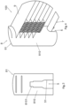
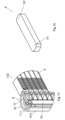
Fig. 1 is a schematic partial enlarged perspective view of a heat exchanger according to a first embodiment of the present invention; -
Fig. 2 is a schematic partial enlarged sectional view of the heat exchanger shown inFig. 1 ; -
Fig. 3 is a schematic partial enlarged right view of the header of the heat exchanger shown inFig. 1 ; -
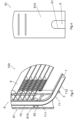
Fig. 4 is a schematic partial enlarged perspective view of a heat exchanger according to a second embodiment of the present invention; -
Fig. 5 is a schematic partial enlarged sectional view of the heat exchanger shown inFig. 4 ; -
Fig. 6 is a schematic partial enlarged right view of the header of the heat exchanger shown inFig. 4 according to an embodiment of the present invention; -
Fig. 7 is a schematic partial enlarged right view of the header of the heat exchanger shown inFig. 4 according to another embodiment of the present invention; -
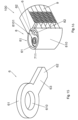
Fig. 8 is a schematic partial enlarged perspective view of a heat exchanger according to a third embodiment of the present invention; -
Fig. 9 is a schematic partial enlarged sectional view of the heat exchanger shown inFig. 8 ; -
Fig. 10 is a schematic enlarged perspective view of the positioning member of the heat exchanger shown inFig. 8 ; -
Fig. 11 is a schematic partial enlarged perspective view of a heat exchanger according to an embodiment of the present invention; -
Fig. 12 is a schematic enlarged perspective view of the positioning member of the heat exchanger shown inFig. 11 ; -
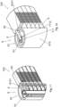
Fig. 13 is a schematic partial enlarged perspective view of a heat exchanger according to a fourth embodiment of the present invention; -
Fig. 14 is a schematic partial enlarged sectional view of the heat exchanger shown inFig. 13 ; -
Fig. 15 is a schematic enlarged perspective view of the positioning member of the heat exchanger shown inFig. 13 ; -
Fig. 16 is a schematic partial enlarged perspective view of a heat exchanger according to a fifth embodiment of the present invention; -
Fig. 17 is a schematic partial enlarged sectional view of the heat exchanger shown inFig. 16 ; -
Fig. 18 is a schematic partial enlarged perspective view of a heat exchanger according to a sixth embodiment of the present invention; -
Fig. 19 is a schematic partial enlarged sectional view of the heat exchanger shown inFig. 18 ; -
Fig. 20 is a schematic enlarged perspective view of the positioning member of the heat exchanger shown inFig. 18 ; -
Fig. 21 is a schematic partial enlarged perspective view of a heat exchanger according to a seventh embodiment of the present invention; -
Fig. 22 is a schematic partial enlarged sectional view of the heat exchanger shown inFig. 21 ; -
Fig. 23 is a schematic enlarged perspective view of the positioning member of the heat exchanger shown inFig. 21 ; -
Fig. 24 is a schematic partial enlarged perspective view of a heat exchanger according to an eighth embodiment of the present invention; -
Fig. 25 is a schematic partial enlarged sectional view of the heat exchanger shown inFig. 24 ; and -
Fig. 26 is a schematic enlarged perspective view of the positioning member of the heat exchanger shown inFig. 24 . - The present invention is explained further below in conjunction with the accompanying drawings and specific implementations.
- Referring to
Figs. 1 to 26 , aheat exchanger 100 according to an embodiment of the present invention comprises:heat exchange tubes 9; and aheader assembly 8, wherein ends of theheat exchange tubes 9 are connected to aheader 81 of theheader assembly 8. Theheat exchanger 100 further comprises fins arranged alternately with theheat exchange tubes 9. - Referring to
Figs. 1 to 26 , according to an embodiment of the present invention, the header assembly 8 comprises: a header 81, the header 81 comprising: a header wall 810, and a recess 8101 on the header wall or an opening 8101 penetrating the header wall 810 at an end of the header wall 810; an end cap 82, the end cap 82 being provided at the end of the header wall 810 (for example in the header wall 810) to close the end of the header 81, the end cap 82 having a hole 820, and the opening or recess 8101 being at a side of the end cap 82 that faces an end face of the end of the header wall 810; a distribution pipe 7, the distribution pipe 7 comprising a distribution part 70 and a connection part 71, the connection part 71 projecting from the end cap 82 through the hole 820 of the end cap 82 from the distribution part 70; and a positioning member 6, the positioning member 6 having a first end 61 and a second end 62, the first end 61 of the positioning member 6 being connected to the connection part 71 of the distribution pipe 7, and the second end 62 of the positioning member 6 being engaged in the opening or recess 8101 of the header wall 810 of the header 81. - Referring to
Figs. 2 ,5 and8 to 17 , according to an embodiment of the present invention, thefirst end 61 of thepositioning member 6 has a hole or notch 610, and theconnection part 71 of thedistribution pipe 7 is inserted into the hole or notch 610 of thefirst end 61 of thepositioning member 6. Thesecond end 62 of thepositioning member 6 may have a rectangular cross section. -
Figures 8 to 12 show embodiments in which thedistribution pipe 7 is positioned in the axial direction of theheader 81;Figures 8 ,9, and 10 show an embodiment in which thefirst end 61 of thepositioning member 6 has a hole, whileFigures 11 and 12 show an embodiment in which thefirst end 61 of thepositioning member 6 has a notch. For other types ofpositioning members 6 with a hole in thefirst end 61, the hole may also be replaced by a notch. - Referring to
Figs. 2 ,3 ,8 ,9 ,11 ,13 ,14 ,16 to 19 and21 , according to embodiments of the present invention, the opening orrecess 8101 of theheader wall 810 is a notch sunk from an end face of the end of theheader wall 810. - Referring to
Figs. 2 and13 to 26 , according to embodiments of the present invention, the positioningmember 6 extends in a direction intersecting the axial direction of theheader 81, thereby positioning thedistribution pipe 7 in a radial direction of theheader 81. - Referring to
Figs. 18 to 26 , according to embodiments of the present invention, theconnection part 71 of thedistribution pipe 7 has anopening 7110 penetrating a pipe wall 710 of theconnection part 71, the positioningmember 6 has a rod-like shape, and thefirst end 61 of thepositioning member 6 is inserted into theopening 7110 of theconnection part 71 of thedistribution pipe 7 in a direction intersecting the axial direction of theconnection part 71 of thedistribution pipe 7. Theopening 7110 of theconnection part 71 of thedistribution pipe 7 may be a notch sunk from an end face of theconnection part 71. The positioningmember 6 may have a rectangular, circular or trapezoidal cross section. - Referring to
Figs. 2 ,13 ,14 ,16 ,17, 18 ,19 ,21, 22 ,24 and25 , according to embodiments of the present invention, theconnection part 71 of thedistribution pipe 7 comprises afirst connection part 711 extending in the axial direction of thedistribution pipe 7. - Referring to
Figs. 8 ,9 and11 , according to embodiments of the present invention, theconnection part 71 of thedistribution pipe 7 comprises afirst connection part 711 extending in the axial direction of thedistribution pipe 7, and asecond connection part 712 which is connected to thefirst connection part 711 and bent at a predetermined angle (for example, 90 degrees) relative to thefirst connection part 711; and thefirst end 61 of thepositioning member 6 is connected to thesecond connection part 712 of theconnection part 71 of thedistribution pipe 7. The positioningmember 6 also has anintermediate part 63 between thefirst end 61 and thesecond end 62, and thesecond end 62 of thepositioning member 6 has abent part 64 which is bent at a predetermined angle relative to theintermediate part 63 of thepositioning member 6, thebent part 64 being engaged in the opening orrecess 8101 of theheader wall 810 of theheader 81. - Referring to
Figs. 1 to 7 , according to embodiments of the present invention, theconnection part 71 of thedistribution pipe 7 comprises afirst connection part 711 extending in the axial direction of thedistribution pipe 7, and asecond connection part 712 which is connected to thefirst connection part 711 and bent at a predetermined angle (for example, 90 degrees) relative to thefirst connection part 711; and theheader 81 further comprises aslot 5 penetrating theheader wall 810 at the end of theheader wall 810, theslot 5 comprising afirst slot part 51 sunk from the end face of the end of theheader wall 810, and thesecond connection part 712 of thedistribution pipe 7 is in thefirst slot part 51. Referring toFig. 3 , the opening orrecess 8101 of theheader wall 810 may be a notch sunk from thefirst slot part 51 in theheader wall 810 in a direction away from the end face of the end of theheader wall 810. Thedistribution pipe 7 may not be in contact with a wall of theslot 5. Lengthening the header so that the distribution pipe is located in theslot 5 may have the effect of protecting the distribution pipe. The distribution pipe may be positioned by means of thepositioning member 6. The distribution pipe may also be engaged in theslot 5, to provide further positioning for the distribution pipe. - Referring to
Figures 1 to 7 , in particularFigure 7 , according to embodiments of the present invention, theconnection part 71 of thedistribution pipe 7 comprises afirst connection part 711 extending in the axial direction of thedistribution pipe 7, and asecond connection part 712 which is connected to thefirst connection part 711 and bent at a predetermined angle (for example, 90 degrees) relative to thefirst connection part 711; and theheader 81 further comprises aslot 5 penetrating theheader wall 810 at the end of theheader wall 810, theslot 5 comprising afirst slot part 51 and asecond slot part 52; thesecond slot part 52 is sunk from the end face of the end of theheader wall 810, and thefirst slot part 51 extends in a direction intersecting the second slot part 52 (e.g. a direction perpendicular to the second slot part 52) from that end of thesecond slot part 52 which is remote from the end face of the end of theheader wall 810; thefirst slot part 51 has slot walls opposite each other in the axial direction of theheader 81, and thesecond connection part 712 of thedistribution pipe 7 is in thefirst slot part 51. Referring toFig. 3 , the opening orrecess 8101 of theheader wall 810 is a notch sunk from thesecond slot part 52 in theheader wall 810 in a direction away from the end face of the end of theheader wall 810. In the embodiment shown inFigs. 4 to 6 , there is no positioningmember 6; the distribution pipe is engaged in theslot 5, and theslot 5 serves a positioning function and also serves to protect the distribution pipe. In addition, providing thefirst slot part 51 and thesecond slot part 52 may facilitate the insertion of one end of thepositioning member 6 into the opening or recess of the header. - By using the header assembly and the heat exchanger according to the embodiments of the present invention, the quality of the heat exchanger may be improved.
- In the header assembly and the heat exchanger according to the embodiments of the present invention, since the positioning member is provided between the distribution pipe and the header, the installation position of the distribution pipe is pre-fixed by means of the positioning member when the distribution pipe is installed. During the process of putting the heat exchanger in a furnace and brazing it, due to the action of the positioning member, the distribution pipe will not experience positional deflection even if it is affected by high temperature and gravity, thereby improving the installation precision of the distribution pipe and improving the heat exchange performance.
- Although the above embodiments have been described, certain features in the above embodiments may be combined to form new embodiments.
Claims (7)
- A header assembly (8) for a heat exchanger (100), comprising:a header (81), comprising: a header wall (810),an end cap (82) disposed at the end of the header wall (810) to close the end of the header (81), the end cap (82) having a hole (820),a distribution pipe (7), comprising a distribution part (70) and a connection part (71), the connection part (71) projecting from the end cap (82) through the hole (820) of the end cap (82) from the distribution part (70); wherein:the connection part (71) of the distribution pipe (7) comprises a first connection part (711) extending in the axial direction of the distribution pipe (7), and a second connection part (712) which is connected to the first connection part (711) and bent at a predetermined angle relative to the first connection part (711),the header (81) further comprises a slot (5) penetrating the header wall (810) at the end of the header wall (810), andthe distribution pipe (71) is engaged in the slot (5).
- The header assembly (8) for a heat exchanger (100) as claimed in claim 1, wherein:
the slot (5) comprising a first slot part (51) sunk from the end face of the end of the header wall, and the second connection part (712) of the distribution pipe (7) is in the first slot part (51). - The header assembly (8) for a heat exchanger (100) as claimed in claim 1, wherein: the slot (5) comprising a first slot part (51) and a second slot part (52); the second slot part (52) is sunk from the end face of the end of the header wall (810), and the first slot part (51) extends in a direction intersecting the second slot part (52) from that end of the second slot part (52) which is remote from the end face of the end of the header wall (810); the first slot part (51) has slot walls opposite each other in the axial direction of the header (81), and the second connection part (712) of the distribution pipe (7) is in the first slot part (51).
- The header assembly (8) for a heat exchanger (100) as claimed in any one of the preceding claims, wherein the slot (5) provides positioning for the distribution pipe (7).
- The header assembly (8) for a heat exchanger (100) as claimed in any one of the preceding claims, wherein the slot (5) protects the distribution pipe (7).
- The header assembly (8) for a heat exchanger (100) as claimed in any one of the preceding claims, wherein the predetermined angle is 90 degrees.
- A heat exchanger, comprising:a heat exchange tube (9); andthe header assembly (8) as claimed in any one of the preceding claims, an end of the heat exchange tube (9) being connected to the header (81) of the header assembly (8).
Applications Claiming Priority (3)
| Application Number | Priority Date | Filing Date | Title |
|---|---|---|---|
| CN202021186941.6U CN212431901U (en) | 2020-06-23 | 2020-06-23 | Collecting pipe assembly and heat exchanger |
| PCT/CN2021/096368 WO2021258980A1 (en) | 2020-06-23 | 2021-05-27 | Header assembly and heat exchanger |
| EP21828716.7A EP4170273B1 (en) | 2020-06-23 | 2021-05-27 | Header assembly and heat exchanger |
Related Parent Applications (2)
| Application Number | Title | Priority Date | Filing Date |
|---|---|---|---|
| EP21828716.7A Division EP4170273B1 (en) | 2020-06-23 | 2021-05-27 | Header assembly and heat exchanger |
| EP21828716.7A Division-Into EP4170273B1 (en) | 2020-06-23 | 2021-05-27 | Header assembly and heat exchanger |
Publications (2)
| Publication Number | Publication Date |
|---|---|
| EP4528202A2 true EP4528202A2 (en) | 2025-03-26 |
| EP4528202A3 EP4528202A3 (en) | 2025-06-04 |
Family
ID=74281169
Family Applications (2)
| Application Number | Title | Priority Date | Filing Date |
|---|---|---|---|
| EP21828716.7A Active EP4170273B1 (en) | 2020-06-23 | 2021-05-27 | Header assembly and heat exchanger |
| EP25156753.3A Pending EP4528202A3 (en) | 2020-06-23 | 2021-05-27 | Header assembly and heat exchanger |
Family Applications Before (1)
| Application Number | Title | Priority Date | Filing Date |
|---|---|---|---|
| EP21828716.7A Active EP4170273B1 (en) | 2020-06-23 | 2021-05-27 | Header assembly and heat exchanger |
Country Status (6)
| Country | Link |
|---|---|
| US (1) | US12181232B2 (en) |
| EP (2) | EP4170273B1 (en) |
| CN (1) | CN212431901U (en) |
| MX (2) | MX2022015876A (en) |
| PL (1) | PL4170273T3 (en) |
| WO (1) | WO2021258980A1 (en) |
Families Citing this family (2)
| Publication number | Priority date | Publication date | Assignee | Title |
|---|---|---|---|---|
| CN212431901U (en) | 2020-06-23 | 2021-01-29 | 丹佛斯有限公司 | Collecting pipe assembly and heat exchanger |
| CN218583473U (en) * | 2022-09-09 | 2023-03-07 | 浙江盾安热工科技有限公司 | Heat exchanger |
Family Cites Families (11)
| Publication number | Priority date | Publication date | Assignee | Title |
|---|---|---|---|---|
| JP2747379B2 (en) * | 1991-05-31 | 1998-05-06 | 昭和アルミニウム株式会社 | Heat exchanger |
| US5429182A (en) * | 1993-09-08 | 1995-07-04 | Showa Aluminum Corporation | Heat exchanger having inlet and outlet pipes for a heat exchanging medium and a method of making same |
| JPH08219680A (en) * | 1995-02-07 | 1996-08-30 | Showa Alum Corp | Heat-exchanger |
| JPH10141887A (en) * | 1996-11-05 | 1998-05-29 | Calsonic Corp | Heat exchanger header with pipe connection pipe |
| JP2000018874A (en) * | 1998-06-24 | 2000-01-18 | Nippon Light Metal Co Ltd | Heat exchanger |
| US8516701B2 (en) * | 2010-05-12 | 2013-08-27 | Delphi Technologies, Inc. | Manifold bending support and method for using same |
| US8408284B2 (en) * | 2011-05-05 | 2013-04-02 | Delphi Technologies, Inc. | Heat exchanger assembly |
| CN104880115B (en) | 2014-02-27 | 2018-03-16 | 杭州三花研究院有限公司 | Flow collection pipe component and heat exchanger |
| CN204346209U (en) * | 2014-11-13 | 2015-05-20 | 浙江盾安热工科技有限公司 | A kind of new type heat exchanger |
| CN204830986U (en) | 2015-07-10 | 2015-12-02 | 杭州三花微通道换热器有限公司 | Heat exchanger |
| CN212431901U (en) | 2020-06-23 | 2021-01-29 | 丹佛斯有限公司 | Collecting pipe assembly and heat exchanger |
-
2020
- 2020-06-23 CN CN202021186941.6U patent/CN212431901U/en active Active
-
2021
- 2021-05-27 PL PL21828716.7T patent/PL4170273T3/en unknown
- 2021-05-27 US US18/002,668 patent/US12181232B2/en active Active
- 2021-05-27 MX MX2022015876A patent/MX2022015876A/en unknown
- 2021-05-27 EP EP21828716.7A patent/EP4170273B1/en active Active
- 2021-05-27 EP EP25156753.3A patent/EP4528202A3/en active Pending
- 2021-05-27 WO PCT/CN2021/096368 patent/WO2021258980A1/en not_active Ceased
-
2022
- 2022-12-13 MX MX2026001339A patent/MX2026001339A/en unknown
Also Published As
| Publication number | Publication date |
|---|---|
| WO2021258980A1 (en) | 2021-12-30 |
| MX2026001339A (en) | 2026-03-02 |
| EP4170273A1 (en) | 2023-04-26 |
| MX2022015876A (en) | 2023-01-24 |
| US12181232B2 (en) | 2024-12-31 |
| PL4170273T3 (en) | 2025-07-21 |
| EP4170273B1 (en) | 2025-03-19 |
| EP4170273A4 (en) | 2024-06-26 |
| US20230251046A1 (en) | 2023-08-10 |
| EP4528202A3 (en) | 2025-06-04 |
| CN212431901U (en) | 2021-01-29 |
Similar Documents
| Publication | Publication Date | Title |
|---|---|---|
| US5052478A (en) | Pipe for coolant condenser | |
| EP4170273B1 (en) | Header assembly and heat exchanger | |
| US10006679B2 (en) | Device for a heat exchanger for collecting and distributing a heat transfer fluid | |
| JP5390417B2 (en) | Heat exchanger and manufacturing method thereof | |
| EP3193121B1 (en) | Heat exchanger | |
| JP2011064403A (en) | Heat exchanger, fin for heat exchanger and its manufacturing method | |
| EP4290164A1 (en) | Collecting tube assembly and heat exchanger | |
| US20250012522A1 (en) | Fixing structure and insertion-plate-type heat exchanger having same | |
| JP5185655B2 (en) | Tube connection structure of heat exchanger | |
| US6231088B1 (en) | Heat exchanger header box connector and method of fixing same | |
| US11598590B2 (en) | Heat exchanger | |
| JP6125024B2 (en) | Heat exchanger, air conditioner using the heat exchanger, and method for manufacturing the heat exchanger | |
| JP6826133B2 (en) | Heat exchanger and refrigeration cycle equipment | |
| EP1970661A1 (en) | Heat exchanger | |
| JP4291644B2 (en) | Heat exchanger | |
| JP2006207966A (en) | Heat exchanger | |
| JP2019199978A (en) | Heat exchanger | |
| EP1744116A2 (en) | Heat exchanger | |
| KR101182185B1 (en) | A Structure and Assembling Method for a Heat Exchanger | |
| JP2023090309A (en) | Misassembly prevention structure for combined parts and heat exchanger having such structure | |
| US20200182548A1 (en) | Heat exchanger | |
| CN218410801U (en) | Heat exchanger | |
| JP2009204218A (en) | Brazing structure of heat exchanger | |
| WO2018066123A1 (en) | Heat exchanger | |
| CN120212771A (en) | Heat exchanger, header assembly, and heat exchanger processing method |
Legal Events
| Date | Code | Title | Description |
|---|---|---|---|
| PUAI | Public reference made under article 153(3) epc to a published international application that has entered the european phase |
Free format text: ORIGINAL CODE: 0009012 |
|
| STAA | Information on the status of an ep patent application or granted ep patent |
Free format text: STATUS: THE APPLICATION HAS BEEN PUBLISHED |
|
| AC | Divisional application: reference to earlier application |
Ref document number: 4170273 Country of ref document: EP Kind code of ref document: P |
|
| AK | Designated contracting states |
Kind code of ref document: A2 Designated state(s): AL AT BE BG CH CY CZ DE DK EE ES FI FR GB GR HR HU IE IS IT LI LT LU LV MC MK MT NL NO PL PT RO RS SE SI SK SM TR |
|
| REG | Reference to a national code |
Ref country code: DE Ref legal event code: R079 Free format text: PREVIOUS MAIN CLASS: F28D0001053000 Ipc: F28F0009020000 |
|
| PUAL | Search report despatched |
Free format text: ORIGINAL CODE: 0009013 |
|
| AK | Designated contracting states |
Kind code of ref document: A3 Designated state(s): AL AT BE BG CH CY CZ DE DK EE ES FI FR GB GR HR HU IE IS IT LI LT LU LV MC MK MT NL NO PL PT RO RS SE SI SK SM TR |
|
| RIC1 | Information provided on ipc code assigned before grant |
Ipc: F28D 1/053 20060101ALI20250425BHEP Ipc: F28F 9/02 20060101AFI20250425BHEP |
|
| STAA | Information on the status of an ep patent application or granted ep patent |
Free format text: STATUS: REQUEST FOR EXAMINATION WAS MADE |
|
| 17P | Request for examination filed |
Effective date: 20250926 |
|
| STAA | Information on the status of an ep patent application or granted ep patent |
Free format text: STATUS: EXAMINATION IS IN PROGRESS |
|
| 17Q | First examination report despatched |
Effective date: 20260423 |