EP4528188A1 - Refrigerator - Google Patents
Refrigerator Download PDFInfo
- Publication number
- EP4528188A1 EP4528188A1 EP23811938.2A EP23811938A EP4528188A1 EP 4528188 A1 EP4528188 A1 EP 4528188A1 EP 23811938 A EP23811938 A EP 23811938A EP 4528188 A1 EP4528188 A1 EP 4528188A1
- Authority
- EP
- European Patent Office
- Prior art keywords
- refrigerator
- compressor
- spacer
- mounting portion
- machine compartment
- Prior art date
- Legal status (The legal status is an assumption and is not a legal conclusion. Google has not performed a legal analysis and makes no representation as to the accuracy of the status listed.)
- Pending
Links
Images




Classifications
-
- F—MECHANICAL ENGINEERING; LIGHTING; HEATING; WEAPONS; BLASTING
- F25—REFRIGERATION OR COOLING; COMBINED HEATING AND REFRIGERATION SYSTEMS; HEAT PUMP SYSTEMS; MANUFACTURE OR STORAGE OF ICE; LIQUEFACTION SOLIDIFICATION OF GASES
- F25D—REFRIGERATORS; COLD ROOMS; ICE-BOXES; COOLING OR FREEZING APPARATUS NOT OTHERWISE PROVIDED FOR
- F25D23/00—General constructional features
- F25D23/02—Doors; Covers
- F25D23/028—Details
-
- F—MECHANICAL ENGINEERING; LIGHTING; HEATING; WEAPONS; BLASTING
- F25—REFRIGERATION OR COOLING; COMBINED HEATING AND REFRIGERATION SYSTEMS; HEAT PUMP SYSTEMS; MANUFACTURE OR STORAGE OF ICE; LIQUEFACTION SOLIDIFICATION OF GASES
- F25D—REFRIGERATORS; COLD ROOMS; ICE-BOXES; COOLING OR FREEZING APPARATUS NOT OTHERWISE PROVIDED FOR
- F25D23/00—General constructional features
- F25D23/006—General constructional features for mounting refrigerating machinery components
-
- F—MECHANICAL ENGINEERING; LIGHTING; HEATING; WEAPONS; BLASTING
- F25—REFRIGERATION OR COOLING; COMBINED HEATING AND REFRIGERATION SYSTEMS; HEAT PUMP SYSTEMS; MANUFACTURE OR STORAGE OF ICE; LIQUEFACTION SOLIDIFICATION OF GASES
- F25B—REFRIGERATION MACHINES, PLANTS OR SYSTEMS; COMBINED HEATING AND REFRIGERATION SYSTEMS; HEAT PUMP SYSTEMS
- F25B31/00—Compressor arrangements
-
- F—MECHANICAL ENGINEERING; LIGHTING; HEATING; WEAPONS; BLASTING
- F25—REFRIGERATION OR COOLING; COMBINED HEATING AND REFRIGERATION SYSTEMS; HEAT PUMP SYSTEMS; MANUFACTURE OR STORAGE OF ICE; LIQUEFACTION SOLIDIFICATION OF GASES
- F25D—REFRIGERATORS; COLD ROOMS; ICE-BOXES; COOLING OR FREEZING APPARATUS NOT OTHERWISE PROVIDED FOR
- F25D19/00—Arrangement or mounting of refrigeration units with respect to devices or objects to be refrigerated, e.g. infrared detectors
-
- F—MECHANICAL ENGINEERING; LIGHTING; HEATING; WEAPONS; BLASTING
- F25—REFRIGERATION OR COOLING; COMBINED HEATING AND REFRIGERATION SYSTEMS; HEAT PUMP SYSTEMS; MANUFACTURE OR STORAGE OF ICE; LIQUEFACTION SOLIDIFICATION OF GASES
- F25B—REFRIGERATION MACHINES, PLANTS OR SYSTEMS; COMBINED HEATING AND REFRIGERATION SYSTEMS; HEAT PUMP SYSTEMS
- F25B2500/00—Problems to be solved
- F25B2500/13—Vibrations
-
- F—MECHANICAL ENGINEERING; LIGHTING; HEATING; WEAPONS; BLASTING
- F25—REFRIGERATION OR COOLING; COMBINED HEATING AND REFRIGERATION SYSTEMS; HEAT PUMP SYSTEMS; MANUFACTURE OR STORAGE OF ICE; LIQUEFACTION SOLIDIFICATION OF GASES
- F25B—REFRIGERATION MACHINES, PLANTS OR SYSTEMS; COMBINED HEATING AND REFRIGERATION SYSTEMS; HEAT PUMP SYSTEMS
- F25B2700/00—Sensing or detecting of parameters; Sensors therefor
- F25B2700/21—Temperatures
- F25B2700/2115—Temperatures of a compressor or the drive means therefor
- F25B2700/21152—Temperatures of a compressor or the drive means therefor at the discharge side of the compressor
-
- F—MECHANICAL ENGINEERING; LIGHTING; HEATING; WEAPONS; BLASTING
- F25—REFRIGERATION OR COOLING; COMBINED HEATING AND REFRIGERATION SYSTEMS; HEAT PUMP SYSTEMS; MANUFACTURE OR STORAGE OF ICE; LIQUEFACTION SOLIDIFICATION OF GASES
- F25D—REFRIGERATORS; COLD ROOMS; ICE-BOXES; COOLING OR FREEZING APPARATUS NOT OTHERWISE PROVIDED FOR
- F25D2400/00—General features of, or devices for refrigerators, cold rooms, ice-boxes, or for cooling or freezing apparatus not covered by any other subclass
- F25D2400/32—Removal, transportation or shipping of refrigerating devices from one location to another
Definitions
- the present disclosure relates to a refrigerator having a structure capable of minimizing the movement of a compressor such that refrigerators are loaded into a container, and then additional refrigerators can be loaded by laying them down in the remaining space at a top thereof to reduce logistics costs.
- a refrigerator is an apparatus that lowers a temperature inside the refrigerator by discharging cold air generated by a refrigeration cycle including a compressor, a condenser, an expansion valve, and an evaporator so as to freeze or refrigerate food, and the like.
- a refrigerator which is a storage compartment, generally includes a freezing compartment in which food or beverages are kept at sub-zero temperatures, and a refrigerating chamber in which food or beverages are primarily kept at low above-zero temperatures.
- Refrigerators may be divided into a top mount type in which the freezing compartment is disposed above the refrigerating compartment, a bottom freezer type in which the freezing compartment is disposed below the refrigerating compartment, and a side by side type in which the freezing compartment and the refrigerating compartment are partitioned into left and right sides.
- refrigerators that have a freezing compartment and a refrigerating compartment
- refrigerators that open and close a single storage space inside the cabinet with a single door.
- the door In a refrigerator that opens and closes with a single door, the door may be rotatably mounted on one side of the cabinet, and the freezing compartment may be configured to partition a portion of the storage space so as to have a freezing compartment door mounted separately on a front surface thereof.
- the freezing compartment may be partitioned from the refrigerating compartment by the freezing compartment door and a partition wall so as to maintain a lower temperature than the refrigerator compartment constituting the remaining space of the storage space.
- the side-by-side refrigerators have storage compartments disposed on both sides with respect to a central partition wall thereof, and two doors are hinged to a main body to open and close each storage compartment.
- Patent Document 1 Korean Patent Publication No. 10-2009-0047934, published on May 13, 2009 discloses a lower packaging material for a refrigerator, including a support member constituting a bottom surface of the refrigerator, a pair of buffer members provided on both side ends of the support member to support both sides of a lower surface of the refrigerator and absorb shock from the refrigerator, at least one horizontal reinforcing member combined with the pair of buffer members to allow a distance between the pair of buffer members to correspond to a width of the refrigerator; and a vertical reinforcing member provided on one side of the horizontal reinforcing member to prevent the support member from being deformed.
- Patent Document 1 has an advantage of preventing the refrigerator from tipping over or falling due to deformation of the lower packaging material, thereby safely transporting the refrigerator without causing property damage.
- Patent Document 1 relates to a structure that simply holds an outer edge of the refrigerator, and does not reflect a structure that minimizes damage caused by a clearance of a compressor located inside the machine compartment of the refrigerator.
- Patent Document 2 Korean Patent Publication No. 10-2001-0048440, published on June 15, 2001 relates to a packaging structure for a lower portion of a refrigerator.
- a lower package in Patent Document 2 includes a base made of cardboard, a plurality of support fixtures arranged on the base, and buffer materials located on both end portions of the support fixtures.
- a door support having a support fixture close-contact portion formed at a lower side to allow a support fixture to be in close contact therewith inward, and a cover support portion formed at an upper side to allow a central portion of a front lower cover of the refrigerator to be caught thereon is provided between the lower package and the refrigerator.
- the front lower cover is supported by the door support member at the central portion and by the buffer material at the both end portions, and thus prevented from bending downward.
- an inclined surface is formed on an outer upper portion of the door support to guide, when an outer box is covered, a lower portion of the outer box to an outside of the door support, thereby facilitating packaging work.
- Patent Document 2 simply discloses a structure that supports an outer edge of the refrigerator, but does not reflect a structure that minimizes damage caused by a clearance of a compressor located inside the machine compartment of the refrigerator.
- refrigerators are loaded standing up inside the container, and refrigerators need to be loaded in a laid-down position to maximize the use of the remaining space, and the biggest problem in this case is pipe deformation (crack, leakage, shear) caused by compressor movement inside the refrigerator, and thus the development of a structure for solving the problem is required.
- an aspect of the present disclosure is to provide a refrigerator having a structure for solving a problem in that, when loading refrigerators into a container, the refrigerators are loaded only in an upright state within the container, and the remaining space at a top inside the container is left empty so as to reduce loading efficiency.
- an aspect of the present disclosure is to provide a refrigerator having a structure for solving a problem in that refrigerators are loaded standing up inside the container, and refrigerators need to be loaded in a laid-down position to maximize the use of the remaining space, and the biggest problem in this case is pipe deformation (crack, leakage, shear) caused by compressor movement inside the refrigerator.
- a refrigerator in the present disclosure may include a cabinet provided with a machine compartment on a lower side thereof; a compressor provided in the machine compartment to sag in one direction due to its own weight when the refrigerator is laid down; a rear cover provided in the cabinet to constitute a rear surface of the machine compartment, and provided with a spacer mounting portion; and a spacer provided in the spacer mounting portion, and supported by the compressor in contact therewith when the refrigerator is laid down.
- the spacer mounting portion may be disposed at a position on the rear cover of the machine compartment that comes into contact therewith when the refrigerator sags by a predetermined distance due to an own weight of the compressor when the refrigerator is laid down.
- the spacer may have a rectangular shape with a chamfer at each corner.
- the rear cover may be provided with a plurality of heat dissipation guides having heat dissipation holes disposed to discharge heat inside the machine compartment, wherein at least one heat dissipation guide is disposed on both sides of the spacer mounting portion, respectively.
- the spacer may be formed of an ethylene propylene diene monomer (EPDM) material.
- EPDM ethylene propylene diene monomer
- the rear cover may be provided with a deformation-prevention mounting portion on a surface opposite to a surface provided with the spacer mounting portion, and the deformation-prevention mounting portion may be provided with a deformation preventing portion to reduce a maximum plastic strain applied to a bottom cover provided with the compressor due to sagging of the compressor, wherein the deformation-prevention mounting portion is provided on an opposite side of the spacer mounting portion with the rear cover therebetween.
- the rear cover may be provided with a plurality of heat dissipation guides having heat dissipation holes disposed to discharge heat inside the machine compartment, wherein at least one heat dissipation guide is disposed on both sides of the deformation-prevention mounting portion, respectively.
- the deformation preventing portion may be formed of an ethylene propylene diene monomer (EPDM) material.
- EPDM ethylene propylene diene monomer
- the compressor may be a linear compressor.
- the compressor may be provided with a bracket having a coupling hole that is coupled to a bottom cover of the machine compartment, wherein the bottom cover of the machine compartment is provided with a coupling member having a coupling groove to which the bracket is coupled.
- the coupling member may be made of seat rubber.
- a refrigerator of the present disclosure may solve a problem in that, when loading refrigerators into a container, the refrigerators are loaded only in an upright state within the container, and the remaining space at a top inside the container is left empty so as to reduce loading efficiency through a structure in which a spacer is provided in a rear cover of a machine compartment.
- refrigerators may be additionally loaded at a top of the container so as to reduce logistics costs.
- the refrigerator of the present disclosure may solve a problem in that refrigerators need to be loaded standing up inside the container, and loaded in a laid-down position to maximize the use of the remaining space, and the biggest problem case is pipe deformation (crack, leakage, shear) caused by the compressor movement inside the refrigerator.
- the present disclosure may additionally load 11 side-by-side refrigerators so as to improve logistics costs by approximately 30%.
- FIG. 1 is a conceptual view showing a loading space (a) in which refrigerators 100 are loaded in a container 1 and a closed space (b) above the loading space (a)
- FIG. 2 is a conceptual view showing a loading space (a) in which refrigerators 100 are loaded in a container 1 and a closed space (b) above the loading space (a).
- the plurality of refrigerators 100 are loaded into a lower loading space (a) inside the container 1.
- a side-by-side refrigerator 100 is shown, but it is not necessarily limited to the side-by-side refrigerator 100.
- a closed space (b) is formed above a loading space (a) of the container 1 of FIG. 1 , and in a case where the refrigerator 100 cannot be additionally loaded onto the loading space (a), as in FIG. 1 , when a space above the loading space (a) cannot be utilized, it becomes a closed space (b).
- the refrigerators 100 When loading the refrigerators 100 into the container 1, the refrigerators 100 are only loaded in an upright state in the loading space (a) of the container 1, and the closed space (b) at a top inside the container 1 is left empty so as to reduce loading efficiency, and a greater number of the containers 1 must be used to transport the refrigerators 100 so as to increase logistics costs.
- the refrigerators 100 are loaded standing up in the container 1 and the refrigerators 100 need to be loaded in a laid-down position in an additional loading space (c) to maximize the use of the remaining space, and the biggest problem in this case is pipe deformation (crack, leakage, shear) caused by the movement of a compressor 20 inside the refrigerator 100, and thus the development of a structure for solving the problem is required.
- an additional loading space is formed above the loading space (a) of the container 1 of FIG. 2 , and if the refrigerators 100 are additionally loaded into the additional loading space provided above the loading space (a), then the space above the loading space (a) can be utilized.
- the refrigerators 100 when loading the refrigerators 100 into the container 1, the refrigerators 100 are loaded into the loading space (a) of the container 1, and the refrigerators 100 are laid down in the additional loading space at a top inside the container 1 so as to reduce loading efficiency, and a greater number of containers 1 must be used to transport the refrigerator 100 so as to increase logistics costs.
- FIG. 7 is a cross-sectional view showing an example in which the compressor 20 of FIG. 4 is supported on the spacer 40 while being coupled to the bottom cover 31 of the machine compartment 15, and
- FIG. 8 is an enlarged view showing the compressor 20 supported on the spacer 40 in FIG. 7 .
- the refrigerator 100 of the present disclosure includes a cabinet 10 provided with a machine compartment 15 on a lower side thereof, a compressor 20 provided in the machine compartment to sag in one direction due to its own weight when the refrigerator 100 is laid down, a rear cover 30 provided in the cabinet 10 to constitute a rear surface of the machine compartment 15, and provided with a spacer mounting portion 30c, and a spacer 40 provided in the spacer mounting portion 30c, and supported by the compressor 20 in contact therewith when the refrigerator 100 is laid down.
- a maximum stress that can be withstood by the rear cover 30 in a laydown state is further increased by a structure in which the spacer 40 is mounted, thereby enhancing durability.
- machine compartment 15 is disposed on a rear side of a bottom portion of the cabinet 10 to accommodate the compressor 20, which is a component of the refrigeration cycle.
- the compressor 20 for compressing refrigerant a condenser (not shown) through which refrigerant discharged from the compressor 20 flows, and a condensing fan for cooling the condenser may be accommodated inside the machine compartment 15.
- the present disclosure is to solve a problem in that the refrigerators 100 are loaded standing up inside the container 1, and the refrigerators 100 need to be loaded in a laid-down position to maximize the use of the remaining space, and the biggest problem in this case is pipe deformation (crack, leakage, shear) caused by the movement of the compressor 20 inside the refrigerator 100.
- the present disclosure has problems of noise and deformation due to a lot of movement of the compressor 20 in a laydown state in which the refrigerators 100 are laid down to be loaded into the container 1 compared to a standing state in which the refrigerators 100 are standing.
- the spacer 40 may be provided within the machine compartment 15 to minimize the movement of the compressor 20 within the machine compartment 15 so as to prevent noise and deformation.
- the compressor 20 may be mounted on the bottom cover 31 inside the machine compartment 15.
- the machine compartment 15 may be provided at a lower rear end of the refrigerator.
- the compressor 20 may be a linear compressor 20.
- the linear compressor 20 is a known technology, and therefore, a detailed description of the linear compressor 20 will be omitted, and the components included in the drawing will be briefly described later.
- the machine compartment 15 may be formed by a front cover and the rear cover 30 constituting front and rear surfaces of the machine compartment 15.
- the spacer 40 may be provided on the rear cover 30 of the machine compartment 15.
- the rear cover 30 of the machine compartment 15 is a rear surface when the refrigerator 100 is in a standing state, but becomes a bottom surface that comes into contact with the sagging of the compressor 20 when in a laydown state, and therefore, the spacer 40 must be provided on the rear cover 30 of the machine compartment 15 to support the compressor 20 during the sagging of the compressor 20.
- the compressor 20 may be provided with a bracket 20b to couple the compressor 20 to the bottom cover 31 inside the machine compartment 15.
- the bracket 20b supports the compressor 20 at a predetermined distance from a rear wall inside the machine compartment 15 when the refrigerator 100 is in a standing state.
- bracket 20b supports the compressor 20 to come into contact with the rear cover 30 constituting the rear wall inside the machine compartment 15 in the laydown state of the refrigerator 100.
- the compressor 20 sags by a predetermined distance due to its own weight in the laydown state of the refrigerator 100 and comes into contact with the rear wall inside the machine compartment 15.
- the compressor 20 moves up to 15 mm in a front-rear direction of the refrigerator 100 in the laydown state of the refrigerator 100.
- a forward direction of the refrigerator 100 is a direction facing a front surface on which the door is disposed and is a direction facing upward with reference to FIG. 4
- a backward direction thereof is a direction facing a surface opposite to the door on which the door is not disposed and is a direction facing downward with reference to FIG. 4 .
- FIG. 9 is a plan view showing the rear cover 30 of the machine compartment 15
- FIG. 10 is a perspective view showing one side of the rear cover 30 on which the spacer 40 in another example is provided
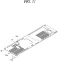
- FIG. 11 is a perspective view showing another side of the rear cover 30 on which a deformation preventing portion 50 is provided.
- the rear cover 30 may be coupled to the cabinet 10 to constitute a rear wall inside the machine compartment 15.
- the rear cover 30 may include heat dissipation guides 30a that are respectively disposed between heat dissipation holes 30b for discharging heat in the machine compartment 15.
- the rear cover 30 of the machine compartment 15 may be provided with the spacer mounting portion 30c into which the spacer 40 is coupled between the plurality of heat dissipation guides 30a.
- the compressor 20 may be supported while being apart from the rear cover 30 of the machine compartment 15.
- the spacer 40 may be formed of a rubber material, for example, may be formed of a material such as polyurethane (PU) foam or ethylene propylene diene monomer (EPDM).
- PU polyurethane
- EPDM ethylene propylene diene monomer
- the spacer 40 may have dimensions of width 45 * height 40 * thickness 15.
- the spacer 40 may be provided with a chamfer at each corner.
- FIG. 8 shows an example in which the compressor 20 sags by a predetermined distance d due to its own weight to come into contact with the spacer 40 in a laydown state.
- d may be 15 mm.
- a maximum stress that can be withstood by the rear cover 30 in a laydown state is further increased by a structure in which the spacer 40 is mounted, thereby enhancing durability.
- the refrigerator 100 of the present disclosure may further include a deformation preventing portion 50 provided on a surface opposite to the spacer mounting portion 30c of the rear cover 30 to prevent deformation of the rear cover 30.
- a deformation-prevention mounting portion 30d may be provided on the rear cover 30 outside the machine compartment 15.
- the deformation preventing portion 50 may be cut by using scissors, a cutting device, or the like.
- the deformation preventing portion 50 may be cut and coupled to the deformation-prevention mounting portion 30d by means of a double-sided tape or adhesive.
- the maximum plastic strain applied to the bottom cover 31 in the laydown state of the refrigerator 100 is further reduced, thereby enhancing durability.
- the bottom cover 31 may be formed as a single member, such as the rear cover 30 described above, or may be formed of different members and coupled to each other.
- the coupling member 31a may be connected to the bottom cover 31 of the machine compartment 15 by a coupling method such as bolts or pins. However, it is not necessarily limited to bolts or pins, and may be coupled by various coupling methods.
- FIG. 14 shows an example of four pins being coupled to the bottom cover 31 by welding.
- the bracket 20b is inserted and coupled into the coupling member 31a.
- the coupling member 31a may be provided with a coupling groove.
- the bracket 20b may be provided with a coupling hole 20b-1.
- the coupling member 31a must be coupled with sufficient rigidity to support the compressor 20 when the refrigerator 100 is laid down.
- the compressor 20 sags downward while being fixed to the coupling member 31a by its own weight, and is supported in contact therewith by the spacer 40 provided on the rear cover 30.
- the compressor 20 has a general configuration, but in the present disclosure, it will be briefly described with reference to FIGS. 5 and 7 .
- the compression section 24 may include a cylinder 26a having a compression space and a piston 26b that is movable in the compression space to compress refrigerant.
- the electric motor may include an outer stator fixedly coupled to an outside of the cylinder 26a, an inner stator spaced apart from an inner side of the outer stator, and a magnet.
- the magnet may be a permanent magnet that moves in a linear reciprocating motion by a mutual electromagnetic force between the outer stator and the inner stator, and is connected to the piston 26b to enable the piston 26b to move in a linear reciprocating motion.
- FIG. 5 a compression support portion 22 provided with a support spring 22a to support the compression section 24 is shown, and a stopper disposed above and below an inner circumference of the shell 20a in the drawing is also shown.
- a discharge member may be provided on a front surface of the cylinder 26a facing the compression space to discharge the compressed refrigerant from the compression section 24 into the shell 20a so as to be discharged to the outside.
- the temperature inside the food storage compartment may be maintained at an average temperature of approximately 3 °C.
- the cabinet 10 has a food storage compartment thereinside.
- the food storage compartment may include a freezing compartment and a refrigerating compartment.
- the cabinet 10 may further include an outer case 13a constituting an exterior, an inner case 13b constituting an interior, and an insulating material (not shown) provided between the outer case 13a and the inner case 13b.
- the refrigerator 100 of the present disclosure may be provided with an evaporator (not shown) between the inner case 13b and the outer case 13a to generate cold air and provide the cold air into the refrigerator, and to this end, although not shown in the drawings of the present disclosure, a component such as a cold air flow duct may be provided.
- a refrigeration cycle in which cold air is supplied by a change in the state of the refrigerant is applied.
- the description of the components of the refrigeration cycle, such as an evaporator, the compressor 20, a condenser, and an expansion valve, will be understood as components applied to the refrigeration cycle of the general refrigerator 100, and thus a detailed description thereof will be omitted.
- doors 12 may be rotatably provided on both sides of the cabinet 10, respectively, so as to open and close the food storage compartment.
- the doors 12 may be hinged on both sides of the cabinet 10, respectively.
- FIG. 1 for the refrigerator 100 of the present disclosure, it is shown as an example of a side-by-side refrigerator 100 in which a food storage compartment is opened and closed by two doors 12.
- a plurality of baskets of various shapes and sizes may be mounted on an inner surface of the door 12.
- the baskets may be disposed in various sizes, and the various sizes of the baskets may store containers of any size desired by a user.
- the basket constitutes a shield to prevent food from falling from the door 12.
- a door liner is disposed at an inside of the door 12, and a basket is coupled to the door liner.
- the door liner constitutes a bottom surface and an inner wall for storing food, and the basket constitutes an outer wall.
- a gasket may be provided around the door liner to prevent the leakage of cold air.
- the cabinet 10 may be provided with a freezing compartment mounting portion in which a freezing compartment is provided at a top thereinside.
- a temperature control module mounting portion in which a temperature control module is disposed may be provided at a bottom of the freezing compartment.
- a front door may be coupled to a freezer frame in a sliding or hinged manner so as to allow the freezer housing to be opened and closed.
- a lower space constitutes a variable space by an elevating partition wall, shelf, or the like.
- a drawer may be provided at a bottom of the food storage compartment to form a space separated from other spaces and configured to store food.
- the drawer may be configured to have a narrower width than a left-right width of the food storage compartment.
- the drawer may constitute, for example, a vegetable compartment for storing vegetables or fruit.
- the drawer is provided at a bottom of the food storage compartment so as to be drawn into and out of the refrigerator.
- the drawer may be open at the front when drawn into the food storage compartment so as to allow to easily remove stored food or the like.
- a shelf may be further provided in the inner case 13b.
- the shelf may be provided horizontally within the food storage compartment.
- the shelf is detachably provided in shelf holders provided on both left and right sides of the inner case 13b to partition the space into sections for placing containers or bowls containing food or ingredients.
- the shelf may be in the form of a rectangular plate having a predetermined thickness.
- a basket is provided at an inside of the door 12.
- the basket constitutes a shield to prevent food from falling from the door 12.
- a door liner is disposed at an inside of the door 12, and a basket is coupled to the door liner.
- the door liner constitutes a bottom surface and an inner wall for storing food, and the basket constitutes an outer wall.
- FIG. 12 is a conceptual diagram showing an example in which the compressor 20 is provided in the machine compartment 15 to measure a displacement of the compressor 20
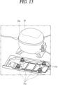
- FIG. 13 is an exploded perspective view showing an example in which the compressor 20 is provided in the machine compartment 15
- FIG. 14 is a perspective view showing an example in which the compressor 20 is provided in the machine compartment 15
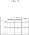
- FIG. 15 is a table showing a displacement of the compressor 20 in x, y, and z axis directions in FIG. 12 .
- the compressor 20 is coupled to the bottom cover 31 within the machine compartment 15 in the drawing, wherein an upper side (a direction in which a Z-axis arrow is pointing) is an upward direction of the refrigerator 100, and a lower side is a downward direction of the refrigerator 100 in the drawing.
- the x, y, and z axis directions are shown in FIG. 12 , wherein for the x-axis direction, a right direction is (+) and a left direction is (-) in the drawing.
- a direction opposite to a direction in which an arrow passes through the drawing is (+)
- a direction opposite thereto is (-).
- an upward direction is (+)
- a downward direction is (-) in the drawing.
- FIG. 15 shows a result of performing an experiment on three models of refrigerators. It can be confirmed that there is a lot of movement in the (+) and (-) directions in the Y direction in a laydown state of the refrigerator 100.
- the rear cover 30 of the machine compartment 15 constitutes a bottom surface
- the bottom cover 31 to which the bracket 20b of the compressor 20 is coupled constitutes a side surface to allow the compressor 20 to sag downward due to its own weight.
- the compressor 20 does not collide with the rear cover 30 by the spacer 40 provided in the spacer mounting portion 30c of the rear cover 30, and is stably supported on the spacer 40.
- the movement of the compressor 20 may be minimized by the spacer 40.
- the deformation preventing portion 50 provided on the deformation-prevention mounting portion 30d on an opposite side of the rear cover 30 the maximum plastic strain applied to the bottom cover 31 due to the sagging of the compressor 20 in the laydown state of the refrigerator 100 is further reduced, thereby enhancing durability.
- the present disclosure may be used in a refrigerator having a structure capable of minimizing the movement of a compressor such that refrigerators are loaded into a container, and then additional refrigerators can be loaded by laying them down in the remaining space at a top thereof to reduce logistics costs.
Landscapes
- Engineering & Computer Science (AREA)
- Physics & Mathematics (AREA)
- Mechanical Engineering (AREA)
- Thermal Sciences (AREA)
- General Engineering & Computer Science (AREA)
- Chemical & Material Sciences (AREA)
- Combustion & Propulsion (AREA)
- Compressor (AREA)
- Refrigerator Housings (AREA)
Abstract
Description
- The present disclosure relates to a refrigerator having a structure capable of minimizing the movement of a compressor such that refrigerators are loaded into a container, and then additional refrigerators can be loaded by laying them down in the remaining space at a top thereof to reduce logistics costs.
- In general, a refrigerator is an apparatus that lowers a temperature inside the refrigerator by discharging cold air generated by a refrigeration cycle including a compressor, a condenser, an expansion valve, and an evaporator so as to freeze or refrigerate food, and the like.
- A refrigerator, which is a storage compartment, generally includes a freezing compartment in which food or beverages are kept at sub-zero temperatures, and a refrigerating chamber in which food or beverages are primarily kept at low above-zero temperatures.
- Refrigerators may be divided into a top mount type in which the freezing compartment is disposed above the refrigerating compartment, a bottom freezer type in which the freezing compartment is disposed below the refrigerating compartment, and a side by side type in which the freezing compartment and the refrigerating compartment are partitioned into left and right sides.
- Among refrigerators that have a freezing compartment and a refrigerating compartment, there are refrigerators that open and close a single storage space inside the cabinet with a single door.
- In a refrigerator that opens and closes with a single door, the door may be rotatably mounted on one side of the cabinet, and the freezing compartment may be configured to partition a portion of the storage space so as to have a freezing compartment door mounted separately on a front surface thereof.
- The freezing compartment may be partitioned from the refrigerating compartment by the freezing compartment door and a partition wall so as to maintain a lower temperature than the refrigerator compartment constituting the remaining space of the storage space.
- Meanwhile, in recent years, as dietary habits change and user preferences become more diverse, the focus has been on making refrigerators larger and more multifunctional, and in response to this trend, side-by-side refrigerators with a larger storage compartment capacity and an internal space partitioned into left and right have become widespread. The side-by-side refrigerators have storage compartments disposed on both sides with respect to a central partition wall thereof, and two doors are hinged to a main body to open and close each storage compartment.
- Patent Document 1 (
Korean Patent Publication No. 10-2009-0047934, published on May 13, 2009 -
Patent Document 1 has an advantage of preventing the refrigerator from tipping over or falling due to deformation of the lower packaging material, thereby safely transporting the refrigerator without causing property damage. - However,
Patent Document 1 relates to a structure that simply holds an outer edge of the refrigerator, and does not reflect a structure that minimizes damage caused by a clearance of a compressor located inside the machine compartment of the refrigerator. - Patent Document 2 (
Korean Patent Publication No. 10-2001-0048440, published on June 15, 2001 Patent Document 2 includes a base made of cardboard, a plurality of support fixtures arranged on the base, and buffer materials located on both end portions of the support fixtures. - In addition, in
Patent Document 2, a door support having a support fixture close-contact portion formed at a lower side to allow a support fixture to be in close contact therewith inward, and a cover support portion formed at an upper side to allow a central portion of a front lower cover of the refrigerator to be caught thereon is provided between the lower package and the refrigerator. The front lower cover is supported by the door support member at the central portion and by the buffer material at the both end portions, and thus prevented from bending downward. Furthermore, an inclined surface is formed on an outer upper portion of the door support to guide, when an outer box is covered, a lower portion of the outer box to an outside of the door support, thereby facilitating packaging work. - However,
Patent Document 2 simply discloses a structure that supports an outer edge of the refrigerator, but does not reflect a structure that minimizes damage caused by a clearance of a compressor located inside the machine compartment of the refrigerator. - Meanwhile, when loading refrigerators into a container, there was a problem in that refrigerators were loaded only in an upright state within the container, and the remaining space at a top inside the container was left empty so as to reduce loading efficiency.
- Accordingly, refrigerators are loaded standing up inside the container, and refrigerators need to be loaded in a laid-down position to maximize the use of the remaining space, and the biggest problem in this case is pipe deformation (crack, leakage, shear) caused by compressor movement inside the refrigerator, and thus the development of a structure for solving the problem is required.
- The present disclosure has been made to solve the foregoing problems, and an aspect of the present disclosure is to provide a refrigerator having a structure that allows a maximum number of refrigerators to be loaded into a container in order to reduce logistics costs.
- Furthermore, an aspect of the present disclosure is to provide a refrigerator having a structure for solving a problem in that, when loading refrigerators into a container, the refrigerators are loaded only in an upright state within the container, and the remaining space at a top inside the container is left empty so as to reduce loading efficiency.
- In addition, an aspect of the present disclosure is to provide a refrigerator having a structure for solving a problem in that refrigerators are loaded standing up inside the container, and refrigerators need to be loaded in a laid-down position to maximize the use of the remaining space, and the biggest problem in this case is pipe deformation (crack, leakage, shear) caused by compressor movement inside the refrigerator.
- In order to solve the foregoing problems, a refrigerator in the present disclosure may include a cabinet provided with a machine compartment on a lower side thereof; a compressor provided in the machine compartment to sag in one direction due to its own weight when the refrigerator is laid down; a rear cover provided in the cabinet to constitute a rear surface of the machine compartment, and provided with a spacer mounting portion; and a spacer provided in the spacer mounting portion, and supported by the compressor in contact therewith when the refrigerator is laid down.
- According to an example associated with the present disclosure, the spacer mounting portion may be disposed at a position on the rear cover of the machine compartment that comes into contact therewith when the refrigerator sags by a predetermined distance due to an own weight of the compressor when the refrigerator is laid down.
- The spacer may have a rectangular shape with a chamfer at each corner.
- The rear cover may be provided with a plurality of heat dissipation guides having heat dissipation holes disposed to discharge heat inside the machine compartment, wherein at least one heat dissipation guide is disposed on both sides of the spacer mounting portion, respectively.
- Preferably, the spacer may be formed of an ethylene propylene diene monomer (EPDM) material.
- According to another example associated with the present disclosure, the rear cover may be provided with a deformation-prevention mounting portion on a surface opposite to a surface provided with the spacer mounting portion, and the deformation-prevention mounting portion may be provided with a deformation preventing portion to reduce a maximum plastic strain applied to a bottom cover provided with the compressor due to sagging of the compressor, wherein the deformation-prevention mounting portion is provided on an opposite side of the spacer mounting portion with the rear cover therebetween.
- The rear cover may be provided with a plurality of heat dissipation guides having heat dissipation holes disposed to discharge heat inside the machine compartment, wherein at least one heat dissipation guide is disposed on both sides of the deformation-prevention mounting portion, respectively.
- Preferably, the deformation preventing portion may be formed of an ethylene propylene diene monomer (EPDM) material.
- Preferably, the compressor may be a linear compressor.
- According to still another example associated with the present disclosure, the compressor may be provided with a bracket having a coupling hole that is coupled to a bottom cover of the machine compartment, wherein the bottom cover of the machine compartment is provided with a coupling member having a coupling groove to which the bracket is coupled.
- As an example, the coupling member may be made of seat rubber.
- A refrigerator of the present disclosure may solve a problem in that, when loading refrigerators into a container, the refrigerators are loaded only in an upright state within the container, and the remaining space at a top inside the container is left empty so as to reduce loading efficiency through a structure in which a spacer is provided in a rear cover of a machine compartment.
- In addition, by means of the refrigerator of the present disclosure, refrigerators may be additionally loaded at a top of the container so as to reduce logistics costs.
- In addition, the refrigerator of the present disclosure may solve a problem in that refrigerators need to be loaded standing up inside the container, and loaded in a laid-down position to maximize the use of the remaining space, and the biggest problem case is pipe deformation (crack, leakage, shear) caused by the compressor movement inside the refrigerator.
- In particular, the present disclosure may additionally load 11 side-by-side refrigerators so as to improve logistics costs by approximately 30%.
-
-
FIG. 1 is a conceptual view showing a loading space in which refrigerators are loaded inside a container and a closed space above the loading space. -
FIG. 2 is a conceptual view showing a loading space in which refrigerators are loaded inside a container and a closed space above the loading space. -
FIG. 3 is a perspective view showing a refrigerator of the present disclosure with a compressor provided at a rear side thereof. -
FIG. 4 is a perspective view showing an example of a compressor provided at a bottom cover. -
FIG. 5 is a cross-sectional view showing an example in which the compressor ofFIG. 4 is spaced apart from a spacer while being coupled to a bottom cover of a machine compartment. -
FIG. 6 is an enlarged view showing a compressor spaced apart from the spacer inFIG. 5 . -
FIG. 7 is a cross-sectional view showing an example in which the compressor ofFIG. 4 is supported on a spacer while being coupled to a bottom cover of a machine compartment. -
FIG. 8 is an enlarged view showing a compressor supported on a spacer inFIG. 7 . -
FIG. 9 is a plan view showing a rear cover of a machine compartment. -
FIG. 10 is a perspective view showing one side of a rear cover on which a spacer in another example is provided. -
FIG. 11 is a perspective view showing another side of a rear cover on which a deformation preventing portion is provided. -
FIG. 12 is a conceptual view showing an example in which a compressor is provided in a machine compartment to measure a displacement of the compressor. -
FIG. 13 is an exploded perspective view showing an example in which a compressor is provided in a machine compartment. -
FIG. 14 is a perspective view showing an example in which a compressor is provided in a machine compartment. -
FIG. 15 is a table showing a displacement of the compressor in x, y, and z axis directions inFIG. 12 . - Hereinafter, a
refrigerator 100 associated with the present disclosure will be described in detail with reference to the accompanying drawings. - In this specification, the same or similar reference numerals are given to the same or similar components even in different embodiments, and redundant descriptions thereof will be omitted.
- In addition, as long as there is no structural or functional contradiction even in different embodiments, a structure applied to one embodiment may be equally applied to another embodiment.
- A singular representation may include a plural representation, unless the context clearly indicates otherwise.
- In describing the embodiments disclosed herein, the detailed description will be omitted when specific description for publicly known technologies to which the invention pertains is judged to obscure the gist of the present disclosure.
- The accompanying drawings are provided only for a better understanding of the embodiments disclosed herein and are not intended to limit technical concepts disclosed herein, and therefore, it should be understood that the accompanying drawings include all modifications, equivalents and substitutes within the concept and technical scope of the present disclosure.
-
FIG. 1 is a conceptual view showing a loading space (a) in whichrefrigerators 100 are loaded in acontainer 1 and a closed space (b) above the loading space (a), andFIG. 2 is a conceptual view showing a loading space (a) in whichrefrigerators 100 are loaded in acontainer 1 and a closed space (b) above the loading space (a). - Hereinafter, with reference to
FIGS. 1 and2 , the loading of therefrigerator 100 into thecontainer 1 in the present disclosure will be described. - Referring to
FIG. 1 , the plurality ofrefrigerators 100 are loaded into a lower loading space (a) inside thecontainer 1. Referring to the drawings of the present disclosure, as an example, a side-by-side refrigerator 100 is shown, but it is not necessarily limited to the side-by-side refrigerator 100. - In addition, an example is shown in which a closed space (b) is formed above a loading space (a) of the
container 1 ofFIG. 1 , and in a case where therefrigerator 100 cannot be additionally loaded onto the loading space (a), as inFIG. 1 , when a space above the loading space (a) cannot be utilized, it becomes a closed space (b). - When loading the
refrigerators 100 into thecontainer 1, therefrigerators 100 are only loaded in an upright state in the loading space (a) of thecontainer 1, and the closed space (b) at a top inside thecontainer 1 is left empty so as to reduce loading efficiency, and a greater number of thecontainers 1 must be used to transport therefrigerators 100 so as to increase logistics costs. - Accordingly, the
refrigerators 100 are loaded standing up in thecontainer 1 and therefrigerators 100 need to be loaded in a laid-down position in an additional loading space (c) to maximize the use of the remaining space, and the biggest problem in this case is pipe deformation (crack, leakage, shear) caused by the movement of acompressor 20 inside therefrigerator 100, and thus the development of a structure for solving the problem is required. - In addition, an example is shown in which an additional loading space is formed above the loading space (a) of the
container 1 ofFIG. 2 , and if therefrigerators 100 are additionally loaded into the additional loading space provided above the loading space (a), then the space above the loading space (a) can be utilized. - As shown in
FIG. 2 , when loading therefrigerators 100 into thecontainer 1, therefrigerators 100 are loaded into the loading space (a) of thecontainer 1, and therefrigerators 100 are laid down in the additional loading space at a top inside thecontainer 1 so as to reduce loading efficiency, and a greater number ofcontainers 1 must be used to transport therefrigerator 100 so as to increase logistics costs. -
FIG. 3 is a perspective view showing therefrigerator 100 of the present disclosure with acompressor 20 provided at a rear side thereof, andFIG. 4 is a perspective view showing an example of thecompressor 20 provided at abottom cover 31. In addition,FIG. 5 is a cross-sectional view showing an example in which thecompressor 20 ofFIG. 4 is spaced apart from aspacer 40 while being coupled to thebottom cover 31 of amachine compartment 15, andFIG. 6 is an enlarged view showing thecompressor 20 spaced apart from thespacer 40 inFIG. 5 . - Meanwhile,
FIG. 7 is a cross-sectional view showing an example in which thecompressor 20 ofFIG. 4 is supported on thespacer 40 while being coupled to thebottom cover 31 of themachine compartment 15, andFIG. 8 is an enlarged view showing thecompressor 20 supported on thespacer 40 inFIG. 7 . - Hereinafter, the
refrigerator 100 of the present disclosure will be described with reference toFIGS. 3 to 8 . - The
refrigerator 100 of the present disclosure includes acabinet 10 provided with amachine compartment 15 on a lower side thereof, acompressor 20 provided in the machine compartment to sag in one direction due to its own weight when therefrigerator 100 is laid down, arear cover 30 provided in thecabinet 10 to constitute a rear surface of themachine compartment 15, and provided with aspacer mounting portion 30c, and aspacer 40 provided in thespacer mounting portion 30c, and supported by thecompressor 20 in contact therewith when therefrigerator 100 is laid down. - In the present disclosure, a laydown state of the
refrigerator 100 denotes a state in which a side surface of the refrigerator is laid down for stacking in the additional loading space (c) inside the container to face a bottom surface thereof. - In the
refrigerator 100 of the present disclosure, a maximum stress that can be withstood by therear cover 30 in a laydown state is further increased by a structure in which thespacer 40 is mounted, thereby enhancing durability. - In addition, the
machine compartment 15 is disposed on a rear side of a bottom portion of thecabinet 10 to accommodate thecompressor 20, which is a component of the refrigeration cycle. - Specifically, the
compressor 20 for compressing refrigerant, a condenser (not shown) through which refrigerant discharged from thecompressor 20 flows, and a condensing fan for cooling the condenser may be accommodated inside themachine compartment 15. - The present disclosure is to solve a problem in that the
refrigerators 100 are loaded standing up inside thecontainer 1, and therefrigerators 100 need to be loaded in a laid-down position to maximize the use of the remaining space, and the biggest problem in this case is pipe deformation (crack, leakage, shear) caused by the movement of thecompressor 20 inside therefrigerator 100. - In particular, the present disclosure has problems of noise and deformation due to a lot of movement of the
compressor 20 in a laydown state in which therefrigerators 100 are laid down to be loaded into thecontainer 1 compared to a standing state in which therefrigerators 100 are standing. - To this end, in the present disclosure, the
spacer 40 may be provided within themachine compartment 15 to minimize the movement of thecompressor 20 within themachine compartment 15 so as to prevent noise and deformation. - The
compressor 20 may be mounted on thebottom cover 31 inside themachine compartment 15. - Referring to
FIG. 3 , themachine compartment 15 may be provided at a lower rear end of the refrigerator. - In the present disclosure, the
compressor 20 may be alinear compressor 20. Thelinear compressor 20 is a known technology, and therefore, a detailed description of thelinear compressor 20 will be omitted, and the components included in the drawing will be briefly described later. - In addition, the
machine compartment 15 may be formed by a front cover and therear cover 30 constituting front and rear surfaces of themachine compartment 15. Thespacer 40 may be provided on therear cover 30 of themachine compartment 15. - The
rear cover 30 of themachine compartment 15 is a rear surface when therefrigerator 100 is in a standing state, but becomes a bottom surface that comes into contact with the sagging of thecompressor 20 when in a laydown state, and therefore, thespacer 40 must be provided on therear cover 30 of themachine compartment 15 to support thecompressor 20 during the sagging of thecompressor 20. - Meanwhile, the
compressor 20 may be provided with abracket 20b to couple thecompressor 20 to thebottom cover 31 inside themachine compartment 15. - The
compressor 20 is coupled to thebracket 20b, and thebracket 20b is fixedly coupled to thebottom cover 31 inside themachine compartment 15. Thebracket 20b may be coupled to thebottom cover 31 by acoupling member 31a, which will be described later. - The
bracket 20b supports thecompressor 20 at a predetermined distance from a rear wall inside themachine compartment 15 when therefrigerator 100 is in a standing state. - In addition, the
bracket 20b supports thecompressor 20 to come into contact with therear cover 30 constituting the rear wall inside themachine compartment 15 in the laydown state of therefrigerator 100. - That is, the
compressor 20 sags by a predetermined distance due to its own weight in the laydown state of therefrigerator 100 and comes into contact with the rear wall inside themachine compartment 15. - As an example, the
compressor 20 moves up to 15 mm in a front-rear direction of therefrigerator 100 in the laydown state of therefrigerator 100. - In the present disclosure, a forward direction of the
refrigerator 100 is a direction facing a front surface on which the door is disposed and is a direction facing upward with reference toFIG. 4 , and a backward direction thereof is a direction facing a surface opposite to the door on which the door is not disposed and is a direction facing downward with reference toFIG. 4 . - If there is no
spacer 40 on the rear wall inside themachine compartment 15 with which thecompressor 20 comes into contact, then it may move forward about 22 to 23 mm and backward about 26.7 to 31.1 mm. In addition, wear of a discharge valve of thecompressor 20 may occur. - As described above, the
compressor 20 may be fixedly connected to thebottom cover 31 inside themachine compartment 15 by thebracket 20b, and in a laydown state, thecompressor 20 may come into contact with therear cover 30 of themachine compartment 15. -
FIG. 9 is a plan view showing therear cover 30 of themachine compartment 15,FIG. 10 is a perspective view showing one side of therear cover 30 on which thespacer 40 in another example is provided, andFIG. 11 is a perspective view showing another side of therear cover 30 on which adeformation preventing portion 50 is provided. - Referring to
FIGS. 9 to 11 , thespacer 40 provided on therear cover 30 will be described in more detail. - The
rear cover 30 may be coupled to thecabinet 10 to constitute a rear wall inside themachine compartment 15. Therear cover 30 may include heat dissipation guides 30a that are respectively disposed betweenheat dissipation holes 30b for discharging heat in themachine compartment 15. - A plurality of heat dissipation guides 30a may be disposed at equal intervals on the
rear cover 30 of themachine compartment 15. Similarly, the plurality ofheat dissipation holes 30b may be disposed between the plurality of heat dissipation guides 30a. - The
heat dissipation holes 30b formed by the heat dissipation guides 30a may be disposed with a plurality of perforation or slit structures, and as shown inFIG. 4 (although not explicitly shown), the plurality ofheat dissipation holes 30b with a slit structure are disposed. - As shown in
FIG. 9 , therear cover 30 of themachine compartment 15 may be provided with thespacer mounting portion 30c into which thespacer 40 is coupled between the plurality of heat dissipation guides 30a. - In addition, the
spacer mounting portion 30c must be disposed at a position on therear cover 30 of themachine compartment 15 that comes into contact therewith when thecompressor 20 sags by a predetermined distance due to its own weight in a laydown state of therefrigerator 100. - The
spacer 40 is coupled to thespacer mounting portion 30c such that thecompressor 20 is supported by being in contact therewith in a laydown state of therefrigerator 100. - In the laydown state of the
refrigerator 100 by thespacer 40, thecompressor 20 may be supported while being apart from therear cover 30 of themachine compartment 15. - The
spacer 40 may be formed of a rubber material, for example, may be formed of a material such as polyurethane (PU) foam or ethylene propylene diene monomer (EPDM). - The
spacer 40 may have dimensions of width 45 *height 40 *thickness 15. Thespacer 40 may be provided with a chamfer at each corner. - The
spacer 40 is preferably large to come into contact with thecompressor 20 or to prevent an impact from being applied thereto, but preferably manufactured not too large so as not to impede performance since there are theheat dissipation guides 30a provided with the heat dissipation holes 30b near thespacer mounting portion 30c. - In addition, the
spacer 40 may be cut by using scissors, a cutting device, or the like. Thespacer 40 may be cut and coupled to thespacer mounting portion 30c by means of a double-sided tape or adhesive. - As a result of carrying out an experiment, when the
spacer 40 is not mounted on therear cover 30 of themachine compartment 15, thecompressor 20 moves 14 mm in a sagging direction. In addition, when thespacer 40 is not mounted, then deformation may occur in therear cover 30 of themachine compartment 15. - On the contrary, when the
spacer 40 is mounted on thespacer mounting portion 30c of therear cover 30 of themachine compartment 15, thecompressor 20 moves 10.3 mm in a sagging direction. - Compared to a case where the
spacer 40 is not mounted, when thespacer 40 is mounted, the structure is partially absorbed by thespacer 40 when thecompressor 20 sags due to its own weight in a laydown state of therefrigerator 100. -
FIG. 7 shows an example in which thecompressor 20 is rotated and sagged by an angle θ determined by its own weight in a laydown state. - In addition,
FIG. 8 shows an example in which thecompressor 20 sags by a predetermined distance d due to its own weight to come into contact with thespacer 40 in a laydown state. As an example, d may be 15 mm. - In order to compare the cases where the
spacer 40 is mounted and not mounted, a model analysis (FE Model) was applied, and the boundary conditions were set to constrain respective fastening portions of therear cover 30 and thebottom cover 31, and thecompressor 20 was dropped at 2500 mm/s to compare maximum stresses that can be withstood by therear cover 30. - As a result of the experiment, when the
spacer 40 was not mounted, the maximum stress that can be withstood by therear cover 30 was 233 MPa, but when thespacer 40 was mounted, the maximum stress applied to therear cover 30 increased to 274 MPa. - As described above, in the
refrigerator 100 of the present disclosure, a maximum stress that can be withstood by therear cover 30 in a laydown state is further increased by a structure in which thespacer 40 is mounted, thereby enhancing durability. - The
refrigerator 100 of the present disclosure may further include adeformation preventing portion 50 provided on a surface opposite to thespacer mounting portion 30c of therear cover 30 to prevent deformation of therear cover 30. - That is, it may be understood that the
spacer 40 is provided on therear cover 30 inside themachine compartment 15, while thedeformation preventing portion 50 is provided on therear cover 30 outside themachine compartment 15. - To this end, a deformation-
prevention mounting portion 30d may be provided on therear cover 30 outside themachine compartment 15. - The deformation-
prevention mounting portion 30d may be coupled between the plurality of heat dissipation guides 30a on therear cover 30 outside themachine compartment 15. - The deformation-
prevention mounting portion 30d may be provided on an opposite side of thespacer mounting portion 30c with therear cover 30 therebetween. - The
deformation preventing portion 50 may be formed of a rubber material, for example, may be formed of a material such as polyurethane (PU) foam or ethylene propylene diene monomer (EPDM). - In addition, the
deformation preventing portion 50 may be cut by using scissors, a cutting device, or the like. Thedeformation preventing portion 50 may be cut and coupled to the deformation-prevention mounting portion 30d by means of a double-sided tape or adhesive. - In order to compare the cases where the
deformation preventing portion 50 is mounted and not mounted, a model analysis (FE Model) was applied, and the boundary conditions were set to constrain respective fastening portions of therear cover 30 and thebottom cover 31, and thecompressor 20 was dropped at 2500 mm/s to compare maximum plastic strains that can be withstood by thebottom cover 31. - As a result of the experiment, when the
deformation preventing portion 50 was not mounted, the maximum plastic strain applied to thebottom cover 31 was 1.3%, but when thedeformation preventing portion 50 was mounted, it was confirmed that the maximum plastic strain applied to thebottom cover 31 was reduced to 0.5%. - In this manner, in the
refrigerator 100 of the present disclosure, due to a structure in which thespacer 40 and thedeformation preventing portion 50 are mounted, the maximum plastic strain applied to thebottom cover 31 in the laydown state of therefrigerator 100 is further reduced, thereby enhancing durability. - In the present disclosure, the
compressor 20 is coupled to thebottom cover 31 of themachine compartment 15. - To this end, the
compressor 20 may be provided with thebracket 20b to be coupled to thebottom cover 31 of themachine compartment 15. - In addition, a bottom of the
machine compartment 15 may be configured with thebottom cover 31, and thecoupling member 31a to which thebracket 20b of thecompressor 20 is coupled is inserted and coupled into thebottom cover 31. - The
bottom cover 31 may be formed as a single member, such as therear cover 30 described above, or may be formed of different members and coupled to each other. - The
coupling member 31a may be connected to thebottom cover 31 of themachine compartment 15 by a coupling method such as bolts or pins. However, it is not necessarily limited to bolts or pins, and may be coupled by various coupling methods. -
FIG. 14 shows an example of four pins being coupled to thebottom cover 31 by welding. - Vibration of the
compressor 20 may be prevented by thecoupling member 31a. - The
coupling member 31a may be, for example, seat rubber, so as to prevent vibration of thecompressor 20. - The
bracket 20b is inserted and coupled into thecoupling member 31a. To this end, thecoupling member 31a may be provided with a coupling groove. In addition, thebracket 20b may be provided with acoupling hole 20b-1. - Of course, the
coupling member 31a must be coupled with sufficient rigidity to support thecompressor 20 when therefrigerator 100 is laid down. - As described above, when the
refrigerator 100 is laid down, thecompressor 20 sags downward while being fixed to thecoupling member 31a by its own weight, and is supported in contact therewith by thespacer 40 provided on therear cover 30. - Meanwhile, the
compressor 20 may be configured to include ashell 20a, acompression section 24, an electric motor, and a discharge member, as shown inFIGS. 5 and7 . - The
compressor 20 has a general configuration, but in the present disclosure, it will be briefly described with reference toFIGS. 5 and7 . - The
shell 20a may constitute an exterior of thecompressor 20, and may be provided with asuction port 20c for sucking refrigerant thereinto and abracket 20b that allows thecompressor 20 to be coupled to thebottom cover 31 of themachine compartment 15. - Although not shown in detail in the drawing, the
compression section 24 may include acylinder 26a having a compression space and apiston 26b that is movable in the compression space to compress refrigerant. - The electric motor may include an outer stator fixedly coupled to an outside of the
cylinder 26a, an inner stator spaced apart from an inner side of the outer stator, and a magnet. - The magnet may be a permanent magnet that moves in a linear reciprocating motion by a mutual electromagnetic force between the outer stator and the inner stator, and is connected to the
piston 26b to enable thepiston 26b to move in a linear reciprocating motion. - A
stator cover 27 may be coupled to the outer stator by bolts. - In addition, a spring 25 may be coupled to the
stator cover 27 to elastically support the electric motor and thecompression section 24 connected thereto. - In addition, in
FIG. 5 , acompression support portion 22 provided with asupport spring 22a to support thecompression section 24 is shown, and a stopper disposed above and below an inner circumference of theshell 20a in the drawing is also shown. - Although not shown in
FIG. 5 , a discharge member may be provided on a front surface of thecylinder 26a facing the compression space to discharge the compressed refrigerant from thecompression section 24 into theshell 20a so as to be discharged to the outside. - Hereinafter, the general internal configuration of the
cabinet 10 related to therefrigerator 100 of the present disclosure will be described. - In the present disclosure, the food storage compartment provided inside the
cabinet 10 may be implemented to include a freezing compartment and a refrigerating compartment, or the entire food storage compartment may be formed only by the freezing compartment. When the entire food storage compartment is formed solely by the freezing compartment, it may be divided into compartments with different temperatures. - The temperature inside the food storage compartment, for example, may be maintained at an average temperature of approximately 3 °C.
- The
cabinet 10 has a food storage compartment thereinside. The food storage compartment may include a freezing compartment and a refrigerating compartment. - In addition, the
cabinet 10 may further include an outer case 13a constituting an exterior, an inner case 13b constituting an interior, and an insulating material (not shown) provided between the outer case 13a and the inner case 13b. - In addition, the
refrigerator 100 of the present disclosure may be provided with an evaporator (not shown) between the inner case 13b and the outer case 13a to generate cold air and provide the cold air into the refrigerator, and to this end, although not shown in the drawings of the present disclosure, a component such as a cold air flow duct may be provided. - Meanwhile, to the
refrigerator 100 of the present disclosure, similar to ageneral refrigerator 100, a refrigeration cycle in which cold air is supplied by a change in the state of the refrigerant is applied. The description of the components of the refrigeration cycle, such as an evaporator, thecompressor 20, a condenser, and an expansion valve, will be understood as components applied to the refrigeration cycle of thegeneral refrigerator 100, and thus a detailed description thereof will be omitted. - In addition,
doors 12 may be rotatably provided on both sides of thecabinet 10, respectively, so as to open and close the food storage compartment. As an example, thedoors 12 may be hinged on both sides of thecabinet 10, respectively. - Referring to
FIG. 1 , for therefrigerator 100 of the present disclosure, it is shown as an example of a side-by-side refrigerator 100 in which a food storage compartment is opened and closed by twodoors 12. - A plurality of baskets of various shapes and sizes may be mounted on an inner surface of the
door 12. - The baskets may be disposed in various sizes, and the various sizes of the baskets may store containers of any size desired by a user.
- The basket constitutes a shield to prevent food from falling from the
door 12. A door liner is disposed at an inside of thedoor 12, and a basket is coupled to the door liner. The door liner constitutes a bottom surface and an inner wall for storing food, and the basket constitutes an outer wall. - Meanwhile, a gasket may be provided around the door liner to prevent the leakage of cold air.
- The freezing compartment may be disposed on an upper side of the food storage compartment provided inside the
cabinet 10. In addition, the freezing compartment may constitute a fixed space at the top. - To this end, the
cabinet 10 may be provided with a freezing compartment mounting portion in which a freezing compartment is provided at a top thereinside. - In addition, a temperature control module mounting portion in which a temperature control module is disposed may be provided at a bottom of the freezing compartment.
- A freezer housing may be provided with an interior in a rectangular shape, and an evaporator may be accommodated in the freezer housing constituting a thickness determined along a perimeter of the rectangle, but a detailed description thereof will be omitted.
- A front door may be coupled to a freezer frame in a sliding or hinged manner so as to allow the freezer housing to be opened and closed.
- In addition, the freezing compartment may further include a cover rear coupled to the front door.
- Meanwhile, a lower space constitutes a variable space by an elevating partition wall, shelf, or the like.
- In addition, a drawer may be provided at a bottom of the food storage compartment to form a space separated from other spaces and configured to store food.
- The drawer may be configured to have a narrower width than a left-right width of the food storage compartment.
- The drawer may constitute, for example, a vegetable compartment for storing vegetables or fruit.
- The drawer is provided at a bottom of the food storage compartment so as to be drawn into and out of the refrigerator.
- The drawer may also be called a tray or drawer compartment.
- In addition, the drawer may be open at the front when drawn into the food storage compartment so as to allow to easily remove stored food or the like.
- Between the freezing compartment above the food storage compartment and the drawer below the food storage compartment, a shelf may be further provided in the inner case 13b.
- The shelf may be provided horizontally within the food storage compartment.
- The shelf is detachably provided in shelf holders provided on both left and right sides of the inner case 13b to partition the space into sections for placing containers or bowls containing food or ingredients.
- The shelf may be in the form of a rectangular plate having a predetermined thickness.
- In addition, a basket is provided at an inside of the
door 12. - The basket constitutes a shield to prevent food from falling from the
door 12. A door liner is disposed at an inside of thedoor 12, and a basket is coupled to the door liner. The door liner constitutes a bottom surface and an inner wall for storing food, and the basket constitutes an outer wall. -
FIG. 12 is a conceptual diagram showing an example in which thecompressor 20 is provided in themachine compartment 15 to measure a displacement of thecompressor 20,FIG. 13 is an exploded perspective view showing an example in which thecompressor 20 is provided in themachine compartment 15,FIG. 14 is a perspective view showing an example in which thecompressor 20 is provided in themachine compartment 15, andFIG. 15 is a table showing a displacement of thecompressor 20 in x, y, and z axis directions inFIG. 12 . - Hereinafter, with reference to
FIGS. 12 and15 , a result of measuring a displacement of thecompressor 20 within themachine compartment 15 will be described. - In
FIG. 12 , as described above, thecompressor 20 is coupled to thebottom cover 31 within themachine compartment 15 in the drawing, wherein an upper side (a direction in which a Z-axis arrow is pointing) is an upward direction of therefrigerator 100, and a lower side is a downward direction of therefrigerator 100 in the drawing. - In addition, the x, y, and z axis directions are shown in
FIG. 12 , wherein for the x-axis direction, a right direction is (+) and a left direction is (-) in the drawing. For the y-axis direction, a direction opposite to a direction in which an arrow passes through the drawing (a direction of sagging due to an own weight) is (+), and a direction opposite thereto is (-). For the z-axis direction, an upward direction (a direction toward a top of the refrigerator 100) is (+), and a downward direction (a direction toward a bottom of the refrigerator 100) is (-) in the drawing. -
FIG. 15 shows a result of performing an experiment on three models of refrigerators. It can be confirmed that there is a lot of movement in the (+) and (-) directions in the Y direction in a laydown state of therefrigerator 100. - Hereinafter, in the
refrigerator 100 of the present disclosure, a process in which thecompressor 20 is supported by thespacer 40 in a laydown state will be described. - When the
refrigerator 100 is laid down to be loaded into the additional loading space (c) of thecontainer 1, therear cover 30 of themachine compartment 15 constitutes a bottom surface, and thebottom cover 31 to which thebracket 20b of thecompressor 20 is coupled constitutes a side surface to allow thecompressor 20 to sag downward due to its own weight. - At this time, the
compressor 20 does not collide with therear cover 30 by thespacer 40 provided in thespacer mounting portion 30c of therear cover 30, and is stably supported on thespacer 40. - In addition, even if an impact is applied to the
refrigerator 100 laid down by an external force during transport of thecontainer 1, the movement of thecompressor 20 may be minimized by thespacer 40. - Meanwhile, by the
deformation preventing portion 50 provided on the deformation-prevention mounting portion 30d on an opposite side of therear cover 30, the maximum plastic strain applied to thebottom cover 31 due to the sagging of thecompressor 20 in the laydown state of therefrigerator 100 is further reduced, thereby enhancing durability. - The configurations and methods according to the above-described embodiments will not be limited to the foregoing
refrigerator 100, and all or part of each embodiment may be selectively combined and configured to make various modifications thereto. - It is obvious to those skilled in the art that the present disclosure can be embodied in other specific forms without departing from the concept and essential characteristics thereof. The above detailed description is therefore to be construed in all aspects as illustrative and not restrictive. The scope of the invention should be determined by reasonable interpretation of the appended claims and all changes that come within the equivalent scope of the invention are included in the scope of the invention.
- The present disclosure may be used in a refrigerator having a structure capable of minimizing the movement of a compressor such that refrigerators are loaded into a container, and then additional refrigerators can be loaded by laying them down in the remaining space at a top thereof to reduce logistics costs.
Claims (11)
- A refrigerator comprising:a cabinet provided with a machine compartment on a lower side thereof;a compressor provided in the machine compartment to sag in one direction due to its own weight when the refrigerator is laid down;a rear cover provided in the cabinet to constitute a rear surface of the machine compartment, and provided with a spacer mounting portion; anda spacer provided in the spacer mounting portion, and supported by the compressor in contact therewith when the refrigerator is laid down.
- The refrigerator of claim 1, wherein the spacer mounting portion is disposed at a position on the rear cover of the machine compartment that comes into contact therewith when the refrigerator sags by a predetermined distance due to an own weight of the compressor when the refrigerator is laid down.
- The refrigerator of claim 1, wherein the spacer has a rectangular shape with a chamfer at each corner.
- The refrigerator of claim 1 or 2, wherein the rear cover is provided with a plurality of heat dissipation guides having heat dissipation holes disposed to discharge heat inside the machine compartment, and wherein at least one heat dissipation guide is disposed on both sides of the spacer mounting portion, respectively.
- The refrigerator of claim 1, wherein the spacer is formed of an ethylene propylene diene monomer (EPDM) material.
- The refrigerator of claim 1 or 2, wherein the rear cover is provided with a deformation-prevention mounting portion on a surface opposite to a surface provided with the spacer mounting portion, and the deformation-prevention mounting portion is provided with a deformation preventing portion to reduce a maximum plastic strain applied to a bottom cover provided with the compressor due to sagging of the compressor, and
wherein the deformation-prevention mounting portion is provided on an opposite side of the spacer mounting portion with the rear cover therebetween. - The refrigerator of claim 6, wherein the rear cover is provided with a plurality of heat dissipation guides having heat dissipation holes disposed to discharge heat inside the machine compartment, and
wherein at least one heat dissipation guide is disposed on both sides of the deformation-prevention mounting portion, respectively. - The refrigerator of claim 6, wherein the deformation preventing portion is formed of an ethylene propylene diene monomer (EPDM) material.
- The refrigerator of claim 1, wherein the compressor is a linear compressor.
- The refrigerator of claim 1, wherein the compressor is provided with a bracket having a coupling hole that is coupled to a bottom cover of the machine compartment, and
wherein the bottom cover of the machine compartment is provided with a coupling member having a coupling groove to which the bracket is coupled. - The refrigerator of claim 10, wherein the coupling member is made of seat rubber.
Applications Claiming Priority (2)
| Application Number | Priority Date | Filing Date | Title |
|---|---|---|---|
| KR1020220064084A KR20230164385A (en) | 2022-05-25 | 2022-05-25 | Refrigerator |
| PCT/KR2023/002132 WO2023229151A1 (en) | 2022-05-25 | 2023-02-14 | Refrigerator |
Publications (2)
| Publication Number | Publication Date |
|---|---|
| EP4528188A1 true EP4528188A1 (en) | 2025-03-26 |
| EP4528188A4 EP4528188A4 (en) | 2025-09-10 |
Family
ID=88919440
Family Applications (1)
| Application Number | Title | Priority Date | Filing Date |
|---|---|---|---|
| EP23811938.2A Pending EP4528188A4 (en) | 2022-05-25 | 2023-02-14 | REFRIGERATOR |
Country Status (3)
| Country | Link |
|---|---|
| EP (1) | EP4528188A4 (en) |
| KR (1) | KR20230164385A (en) |
| WO (1) | WO2023229151A1 (en) |
Family Cites Families (11)
| Publication number | Priority date | Publication date | Assignee | Title |
|---|---|---|---|---|
| JP3370728B2 (en) * | 1993-05-07 | 2003-01-27 | 松下冷機株式会社 | refrigerator |
| JPH0719707A (en) * | 1993-07-07 | 1995-01-20 | Matsushita Refrig Co Ltd | Back surface convection gap holding device for refrigerator |
| KR19990053126A (en) | 1997-12-23 | 1999-07-15 | 전주범 | Heating Control Method of Gas Boiler Using Differential Pressure Gauge |
| KR100323183B1 (en) | 1999-11-26 | 2002-02-04 | 구자홍 | Packing structure for lower portion of refrigerator |
| KR100575680B1 (en) * | 2004-05-18 | 2006-05-03 | 엘지전자 주식회사 | Wine Refrigerator with Dustproof Function |
| US7536099B2 (en) | 2006-05-25 | 2009-05-19 | Nokia Corporation | Camera protection cover |
| KR101455859B1 (en) | 2007-11-09 | 2014-11-03 | 엘지전자 주식회사 | Alower part package for refrigerator |
| TR201009588A1 (en) * | 2010-11-23 | 2012-06-21 | Bsh Ev Aletleri̇ San. Ve Ti̇c. A.Ş. | Household refrigerating appliance with spacer. |
| JP5944709B2 (en) * | 2012-03-22 | 2016-07-05 | 株式会社東芝 | refrigerator |
| CN203022998U (en) * | 2012-12-20 | 2013-06-26 | 海信容声(广东)冷柜有限公司 | Damping device of compressor |
| JP6675058B2 (en) * | 2016-05-13 | 2020-04-01 | パナソニックIpマネジメント株式会社 | refrigerator |
-
2022
- 2022-05-25 KR KR1020220064084A patent/KR20230164385A/en active Pending
-
2023
- 2023-02-14 WO PCT/KR2023/002132 patent/WO2023229151A1/en not_active Ceased
- 2023-02-14 EP EP23811938.2A patent/EP4528188A4/en active Pending
Also Published As
| Publication number | Publication date |
|---|---|
| WO2023229151A1 (en) | 2023-11-30 |
| EP4528188A4 (en) | 2025-09-10 |
| KR20230164385A (en) | 2023-12-04 |
Similar Documents
| Publication | Publication Date | Title |
|---|---|---|
| EP2818814B1 (en) | Refrigerator | |
| KR102289689B1 (en) | Lifting apparatus and refrigerator having the same | |
| KR102629953B1 (en) | Refrigrator | |
| US20180224201A1 (en) | Refrigerator and manufacturing method thereof | |
| US20180087828A1 (en) | Refrigerator | |
| JP6448984B2 (en) | refrigerator | |
| KR102583505B1 (en) | Refrigerator | |
| CN102341666A (en) | Refrigerator | |
| EP2735827B1 (en) | Refrigerator | |
| EP4528188A1 (en) | Refrigerator | |
| JP3722151B1 (en) | refrigerator | |
| JP6744383B2 (en) | refrigerator | |
| JPH116683A (en) | Refrigerator drawer structure | |
| JP2020125903A (en) | refrigerator | |
| KR101884349B1 (en) | Refrigerator | |
| CN100403962C (en) | Shelf device and refrigerator with the same | |
| US10345032B2 (en) | Refrigerator | |
| EP4249836A1 (en) | Refrigerator | |
| JP3969434B2 (en) | refrigerator | |
| KR20230060809A (en) | Refrigerator | |
| JP2003166781A (en) | Refrigerator | |
| JP2021099171A (en) | refrigerator | |
| JP2021188833A (en) | refrigerator | |
| KR20220158575A (en) | Refrigerator | |
| JP7806173B2 (en) | refrigerator |
Legal Events
| Date | Code | Title | Description |
|---|---|---|---|
| STAA | Information on the status of an ep patent application or granted ep patent |
Free format text: STATUS: THE INTERNATIONAL PUBLICATION HAS BEEN MADE |
|
| PUAI | Public reference made under article 153(3) epc to a published international application that has entered the european phase |
Free format text: ORIGINAL CODE: 0009012 |
|
| STAA | Information on the status of an ep patent application or granted ep patent |
Free format text: STATUS: REQUEST FOR EXAMINATION WAS MADE |
|
| 17P | Request for examination filed |
Effective date: 20241217 |
|
| AK | Designated contracting states |
Kind code of ref document: A1 Designated state(s): AL AT BE BG CH CY CZ DE DK EE ES FI FR GB GR HR HU IE IS IT LI LT LU LV MC ME MK MT NL NO PL PT RO RS SE SI SK SM TR |
|
| DAV | Request for validation of the european patent (deleted) | ||
| DAX | Request for extension of the european patent (deleted) | ||
| A4 | Supplementary search report drawn up and despatched |
Effective date: 20250808 |
|
| RIC1 | Information provided on ipc code assigned before grant |
Ipc: F25D 23/02 20060101AFI20250804BHEP Ipc: F25D 19/00 20060101ALI20250804BHEP Ipc: F25B 31/00 20060101ALI20250804BHEP |