EP4528185A1 - Leakage detection for ice maker - Google Patents
Leakage detection for ice maker Download PDFInfo
- Publication number
- EP4528185A1 EP4528185A1 EP23807020.5A EP23807020A EP4528185A1 EP 4528185 A1 EP4528185 A1 EP 4528185A1 EP 23807020 A EP23807020 A EP 23807020A EP 4528185 A1 EP4528185 A1 EP 4528185A1
- Authority
- EP
- European Patent Office
- Prior art keywords
- ice
- mold body
- liquid water
- determining
- ice maker
- Prior art date
- Legal status (The legal status is an assumption and is not a legal conclusion. Google has not performed a legal analysis and makes no representation as to the accuracy of the status listed.)
- Pending
Links
Images




Classifications
-
- F—MECHANICAL ENGINEERING; LIGHTING; HEATING; WEAPONS; BLASTING
- F25—REFRIGERATION OR COOLING; COMBINED HEATING AND REFRIGERATION SYSTEMS; HEAT PUMP SYSTEMS; MANUFACTURE OR STORAGE OF ICE; LIQUEFACTION SOLIDIFICATION OF GASES
- F25C—PRODUCING, WORKING OR HANDLING ICE
- F25C1/00—Producing ice
- F25C1/04—Producing ice by using stationary moulds
-
- F—MECHANICAL ENGINEERING; LIGHTING; HEATING; WEAPONS; BLASTING
- F25—REFRIGERATION OR COOLING; COMBINED HEATING AND REFRIGERATION SYSTEMS; HEAT PUMP SYSTEMS; MANUFACTURE OR STORAGE OF ICE; LIQUEFACTION SOLIDIFICATION OF GASES
- F25C—PRODUCING, WORKING OR HANDLING ICE
- F25C1/00—Producing ice
- F25C1/22—Construction of moulds; Filling devices for moulds
- F25C1/24—Construction of moulds; Filling devices for moulds for refrigerators, e.g. freezing trays
-
- F—MECHANICAL ENGINEERING; LIGHTING; HEATING; WEAPONS; BLASTING
- F25—REFRIGERATION OR COOLING; COMBINED HEATING AND REFRIGERATION SYSTEMS; HEAT PUMP SYSTEMS; MANUFACTURE OR STORAGE OF ICE; LIQUEFACTION SOLIDIFICATION OF GASES
- F25C—PRODUCING, WORKING OR HANDLING ICE
- F25C1/00—Producing ice
- F25C1/22—Construction of moulds; Filling devices for moulds
- F25C1/25—Filling devices for moulds
-
- F—MECHANICAL ENGINEERING; LIGHTING; HEATING; WEAPONS; BLASTING
- F25—REFRIGERATION OR COOLING; COMBINED HEATING AND REFRIGERATION SYSTEMS; HEAT PUMP SYSTEMS; MANUFACTURE OR STORAGE OF ICE; LIQUEFACTION SOLIDIFICATION OF GASES
- F25C—PRODUCING, WORKING OR HANDLING ICE
- F25C5/00—Working or handling ice
- F25C5/02—Apparatus for disintegrating, removing or harvesting ice
- F25C5/04—Apparatus for disintegrating, removing or harvesting ice without the use of saws
- F25C5/06—Apparatus for disintegrating, removing or harvesting ice without the use of saws by deforming bodies with which the ice is in contact, e.g. using inflatable members
-
- F—MECHANICAL ENGINEERING; LIGHTING; HEATING; WEAPONS; BLASTING
- F25—REFRIGERATION OR COOLING; COMBINED HEATING AND REFRIGERATION SYSTEMS; HEAT PUMP SYSTEMS; MANUFACTURE OR STORAGE OF ICE; LIQUEFACTION SOLIDIFICATION OF GASES
- F25C—PRODUCING, WORKING OR HANDLING ICE
- F25C2400/00—Auxiliary features or devices for producing, working or handling ice
- F25C2400/10—Refrigerator units
-
- F—MECHANICAL ENGINEERING; LIGHTING; HEATING; WEAPONS; BLASTING
- F25—REFRIGERATION OR COOLING; COMBINED HEATING AND REFRIGERATION SYSTEMS; HEAT PUMP SYSTEMS; MANUFACTURE OR STORAGE OF ICE; LIQUEFACTION SOLIDIFICATION OF GASES
- F25C—PRODUCING, WORKING OR HANDLING ICE
- F25C2400/00—Auxiliary features or devices for producing, working or handling ice
- F25C2400/14—Water supply
-
- F—MECHANICAL ENGINEERING; LIGHTING; HEATING; WEAPONS; BLASTING
- F25—REFRIGERATION OR COOLING; COMBINED HEATING AND REFRIGERATION SYSTEMS; HEAT PUMP SYSTEMS; MANUFACTURE OR STORAGE OF ICE; LIQUEFACTION SOLIDIFICATION OF GASES
- F25C—PRODUCING, WORKING OR HANDLING ICE
- F25C2500/00—Problems to be solved
- F25C2500/06—Spillage or flooding of water
-
- F—MECHANICAL ENGINEERING; LIGHTING; HEATING; WEAPONS; BLASTING
- F25—REFRIGERATION OR COOLING; COMBINED HEATING AND REFRIGERATION SYSTEMS; HEAT PUMP SYSTEMS; MANUFACTURE OR STORAGE OF ICE; LIQUEFACTION SOLIDIFICATION OF GASES
- F25C—PRODUCING, WORKING OR HANDLING ICE
- F25C2600/00—Control issues
- F25C2600/04—Control means
-
- F—MECHANICAL ENGINEERING; LIGHTING; HEATING; WEAPONS; BLASTING
- F25—REFRIGERATION OR COOLING; COMBINED HEATING AND REFRIGERATION SYSTEMS; HEAT PUMP SYSTEMS; MANUFACTURE OR STORAGE OF ICE; LIQUEFACTION SOLIDIFICATION OF GASES
- F25C—PRODUCING, WORKING OR HANDLING ICE
- F25C2700/00—Sensing or detecting of parameters; Sensors therefor
- F25C2700/04—Level of water
-
- F—MECHANICAL ENGINEERING; LIGHTING; HEATING; WEAPONS; BLASTING
- F25—REFRIGERATION OR COOLING; COMBINED HEATING AND REFRIGERATION SYSTEMS; HEAT PUMP SYSTEMS; MANUFACTURE OR STORAGE OF ICE; LIQUEFACTION SOLIDIFICATION OF GASES
- F25C—PRODUCING, WORKING OR HANDLING ICE
- F25C2700/00—Sensing or detecting of parameters; Sensors therefor
- F25C2700/12—Temperature of ice trays
Definitions
- the present subject matter relates generally to ice maker appliances, and in particular to systems and methods for detecting leaks in such appliances.
- Certain refrigerator appliances include an ice maker.
- An ice maker may also be a stand-alone appliance designed for use in commercial and/or residential kitchens.
- To produce ice liquid water is directed to the ice maker and frozen.
- certain ice makers include a mold body for receiving liquid water. After ice is formed in the mold body, it may be harvested from the mold body and stored within an ice bin or bucket within the refrigerator appliance.
- an amount of the liquid water directed to the mold body may escape from the mold body prior to forming into ice as intended.
- the mold body may develop a crack, one or more sealing elements may wear out, or the mold body may be overfilled.
- a twist tray ice maker may include a partitioned plastic mold that is physically deformed to break the bond formed between ice and the tray, in such ice makers, the ice cubes may be fractured during the twisting process. When such fracturing occurs, a portion of the cubes may remain in the tray, thus resulting in overfilling during the next fill process.
- a method of operating an ice maker appliance includes a mold body.
- the method includes directing liquid water to the mold body and calculating an ice making time after directing the liquid water to the mold body.
- the method also includes determining that the calculated ice making time is less than an allowed ice making time. Because the calculated ice making time is less than an allowed ice making time, it may be determined that at least a portion of the liquid water escaped.
- the method further includes providing a user notification in response to determining that at least the portion of the liquid water escaped.
- a method of operating an ice maker appliance includes a mold body and a harvest motor.
- the method includes directing liquid water to the mold body and determining that ice has formed in the mold body after directing the liquid water to the mold body.
- the method also includes harvesting the ice from the mold body.
- Harvesting the ice from the mold body includes activating the harvest motor.
- the method further includes measuring, during harvesting the ice from the mold body, a torque of the harvest motor and determining that the measured torque of the harvest motor is less than a minimum harvest torque threshold. Because the measured torque of the harvest motor is less than the minimum harvest torque threshold, it may be determined that at least a portion of the liquid water escaped.
- the method further includes providing a user notification in response to determining that at least the portion of the liquid water escaped.
- a method of operating an ice maker appliance includes a mold body and a temperature sensor operable to measure a temperature at the mold body.
- the method includes directing liquid water to the mold body and calculating a temperature change rate of a temperature of the mold body after directing the liquid water to the mold body.
- the method also includes determining that the calculated temperature change rate is greater than a maximum temperature change rate threshold. Because the calculated temperature change rate is greater than the maximum temperature change rate threshold, it may be determined that at least a portion of the liquid water escaped.
- the method further includes providing a user notification in response to determining that at least the portion of the liquid water escaped.
- terms of approximation such as “generally,” or “about” include values within ten percent greater or less than the stated value. When used in the context of an angle or direction, such terms include within ten degrees greater or less than the stated angle or direction.
- “generally vertical” includes directions within ten degrees of vertical in any direction, e.g., clockwise or counterclockwise.
- the terms “first,” “second,” and “third” may be used interchangeably to distinguish one component from another and are not intended to signify location or importance of the individual components.
- FIG. 1 provides a perspective view of a refrigerator appliance 100 according to an exemplary embodiment of the present subject matter.
- Refrigerator appliance 100 includes a cabinet or housing 102 that extends between a top 104 and a bottom 106 along a vertical direction V, between a first side 108 and a second side 110 along a lateral direction L, and between a front side 112 and a rear side 114 along a transverse direction T.
- Each of the vertical direction V, lateral direction L, and transverse direction T are mutually perpendicular to one another.
- Refrigerator doors 128 are rotatably hinged to an edge of housing 102 for selectively accessing fresh food chamber 122.
- a freezer door 130 is arranged below refrigerator doors 128 for selectively accessing freezer chamber 124.
- Freezer door 130 is coupled to a freezer drawer (not shown) slidably mounted within freezer chamber 124.
- Refrigerator doors 128 and freezer door 130 are shown in the closed configuration in FIG. 1 .
- FIG. 1 One skilled in the art will appreciate that other chamber and door configurations are possible and within the scope of the present invention.
- FIG. 2 provides a perspective view of refrigerator appliance 100 shown with refrigerator doors 128 in the open position.
- various storage components are mounted within fresh food chamber 122 to facilitate storage of food items therein as will be understood by those skilled in the art.
- the storage components may include bins 134 and shelves 136. Each of these storage components are configured for receipt of food items (e.g., beverages and/or solid food items, etc.) and may assist with organizing such food items.
- bins 134 may be mounted on refrigerator doors 128 or may slide into a receiving space in fresh food chamber 122. It should be appreciated that the illustrated storage components are used only for the purpose of explanation and that other storage components may be used and may have different sizes, shapes, and configurations.
- Dispensing assembly 140 is generally configured for dispensing liquid water and/or ice. Although an exemplary dispensing assembly 140 is illustrated and described herein, it should be appreciated that variations and modifications may be made to dispensing assembly 140 while remaining within the present subject matter.
- Dispensing assembly 140 and its various components may be positioned at least in part within a dispenser recess 142 defined on one of refrigerator doors 128.
- dispenser recess 142 is defined on a front side 112 of refrigerator appliance 100 such that a user may operate dispensing assembly 140 without opening refrigerator door 128.
- dispenser recess 142 is positioned at a predetermined elevation convenient for a user to access ice and enabling the user to access ice without the need to bend-over.
- dispenser recess 142 is positioned at a level that approximates the chest level of a user.
- refrigerator door 128 may define an icebox 150 ( FIGS. 2 through 4 ) housing an ice maker 200 and an ice storage bin 202 that are configured to supply ice to dispenser recess 142.
- icebox 150 may define an ice making chamber 154 for housing an ice making assembly, a storage mechanism, and a dispensing mechanism.
- control panel 160 is provided for controlling the mode of operation.
- control panel 160 includes one or more selector inputs 162, such as knobs, buttons, touchscreen interfaces, etc., such as a water dispensing button and an ice-dispensing button, for selecting a desired mode of operation such as crushed or non-crushed ice.
- inputs 162 may be used to specify a fill volume or method of operating dispensing assembly 140.
- inputs 162 may be in communication with a processing device or controller 164. Signals generated in controller 164 operate refrigerator appliance 100 and dispensing assembly 140 in response to selector inputs 162.
- a display 166 such as an indicator light or a screen, may be provided on control panel 160. Display 166 may be in communication with controller 164, and may display information in response to signals from controller 164.
- processing device or “controller” may refer to one or more microprocessors or semiconductor devices and is not restricted necessarily to a single element.
- the processing device can be programmed to operate refrigerator appliance 100 and dispensing assembly 140.
- the processing device may include, or be associated with, one or more memory elements (e.g., non-transitory storage media).
- the memory elements include electrically erasable, programmable read only memory (EEPROM).
- EEPROM electrically erasable, programmable read only memory
- the memory elements can store information accessible to the processing device, including instructions that can be executed by processing device.
- the instructions can be software or any set of instructions and/or data that when executed by the processing device, cause the processing device to perform operations.
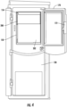
- FIG. 3 provides an interior perspective view of one of the refrigerator doors 128 and FIG. 4 provides an interior elevation view of the door 128 with an access door 170 shown in an open position.
- Refrigerator appliance 100 includes a sub-compartment 150 defined on refrigerator door 128.
- the sub-compartment 150 may be referred to as an "icebox.”
- icebox 150 extends into fresh food chamber 122 when refrigerator door 128 is in the closed position.
- an ice maker 200 may be positioned within the ice box 150.
- the ice maker 200 is generally configured for freezing the water to form ice, e.g., ice pieces such as ice cubes, which may be stored in storage bin 202 and dispensed through discharging outlet 146 by dispensing assembly 140.
- FIG. 4 illustrates the ice maker 200 with an ice storage bin 202 positioned below the ice maker 200 for receiving ice pieces from the ice maker 200, e.g., for receiving the ice after the ice is ejected from the ice maker 200.
- ice from the ice maker 200 is collected and stored in the ice storage bin 202 and supplied to dispenser 144 ( FIG.
- the present disclosure may also be applied to other types and styles of refrigerator appliances such as, e.g., a top mount refrigerator appliance, a side-by-side style refrigerator appliance or a standalone ice maker appliance. Variations and modifications may be made to ice maker 200 while remaining within the scope of the present subject matter. Accordingly, the description herein of the icebox 150 on the door 128 of the fresh food chamber 122 is by way of example only.
- the ice maker 200 may be positioned in the freezer chamber 124, e.g., of the illustrated bottom-mount refrigerator, of a side by side refrigerator, of a top-mount refrigerator, or any other suitable refrigerator appliance.
- the ice maker 200 may also be provided in a standalone ice maker appliance.
- standalone ice maker appliance refers to an appliance of which the sole or primary operation is generating or producing ice
- ice maker appliance includes such appliances as well as appliances with diverse capabilities in addition to making ice, such as a refrigerator appliance equipped with an ice maker, among other possible examples.
- an access door 170 may be hinged to the inside of the refrigerator door 128. Access door 170 permits selective access to icebox 150. Any manner of suitable latch 172 may be configured with icebox 150 to maintain access door 170 in a closed position. As an example, latch 172 may be actuated by a consumer in order to open access door 170 for providing access into icebox 150. Access door 170 can also assist with insulating icebox 150, e.g., by thermally isolating or insulating icebox 150 from fresh food chamber 122.
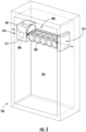
- the ice maker 200 may be a twist tray ice maker.
- the ice maker 200 may include a mount unit 210 positioned in the icebox 150, e.g., mounted on one or more internal surfaces of the icebox 150.
- the mount unit 210 may be coupled to an ice tray 220, e.g., the mount unit 210 may be configured to releasably receive the ice tray 220.
- the ice tray 220 may provide a mold body of the ice maker 200, e.g., the ice tray 220 may include one or more compartments 224 for receiving liquid water therein, and the liquid water may be retained within the compartment(s) 224 until ice is formed (or at least a portion of the liquid water may be retained).
- the ice tray 220 may comprise a flexible, e.g., twistable, material, such as the ice tray 220 may comprise a plastic material which is sufficiently flexible to twist the ice tray 220 in order to promote disengagement, e.g., release, of ice pieces in the ice tray 220, as is understood by those of ordinary skill in the art.
- the mount unit 210 may include a first mount unit 211 and a second mount unit 212.
- the mount units 211, 212 may be spaced apart from one another along a central axis 201 of the ice maker 200.
- a direction of the central axis 201 corresponds to, e.g., is along or parallel to, a longitudinal axis of the ice tray 220 when the ice tray 220 is installed to the mount unit 210.
- the mount units 211, 212 may be spaced apart from one another such as to allow a pair of lips 222 ( FIG. 6 ) of the ice tray 220 separated along the central axis 201 to be received by respective mount units 211, 212.
- the mount unit 210 may include one or more clips 218, e.g., a first clip 218 on the first mount unit 211 and a second clip 218 on the second mount unit 212, and the lip(s) 222 of the ice tray 220 may be configured to be received within and retained by the clip(s) 218, e.g., the lip(s) 222 may each be sized and shaped corresponding to a respective clip 218, such as the external dimensions of the lip 222 or each lip 222 may correspond to internal dimensions of the clip 218 or each clip 218, whereby the lip(s) 222 may be received within and retained by the clip(s) 218.
- the lip(s) 222 may each be sized and shaped corresponding to a respective clip 218, such as the external dimensions of the lip 222 or each lip 222 may correspond to internal dimensions of the clip 218 or each clip 218, whereby the lip(s) 222 may be received within and retained by the clip(s) 218.
- the mount unit 210 includes a rotor 216 configured to rotate relative to a central axis 201.
- the first clip 218 on the first mount unit 211 may be formed integrally with the rotor 216.
- the first mount unit 211 may be fixed to the icebox 150.
- the first mount unit 211 may include a motor or other actuation device 206 operably coupled to the rotor 216 to rotate relative to the central axis 201, e.g., about the central axis 201.
- rotation of the rotor 216 such as by the actuation device 206, causes the ice tray 220 to dump or deposit ice or other contents from the ice tray 220.
- the ice maker 200 may include a dedicated controller 207, e.g., similar to the controller 164 of the refrigerator appliance 100 which is described above.
- the dedicated controller 207 may be in addition to the controller 164 of the refrigerator appliance and may be in communication with the controller 164 of the refrigerator appliance 100, and the controller 207 of the ice maker 200 may be in operative communication with other components of the ice maker 200 and may be configured specifically for controlling or directing operation of such components, e.g., the actuation device 206.
- the ice maker 200 may also include one or more sensors, such as a temperature sensor as will be described further hereinbelow, and the dedicated controller 207 of the ice maker 200 may also be in operative communication with such sensors.
- the controller 207 may cause the actuation device 206 to rotate a first amount, e.g., through a first number of degrees about the central axis 201, to twist the tray 220 and thereby promote release of ice pieces from the compartment 224 thereof, such as rotating the first amount in a first direction followed by rotating the same amount, e.g., the first amount, in a second direction opposite the first direction to twist the tray 220 to release ice pieces from the compartments 224.
- a first amount e.g., through a first number of degrees about the central axis 201
- FIGS. 7 and 8 provide schematic illustrations of various embodiments of an ice maker 200 according to the present disclosure.
- ice maker 200 may include or be provided with a water line 230 which is positioned and configured to direct a flow of liquid water to a mold body 236 of the ice maker 200, e.g., the flow of liquid water may be directed towards and/or into the mold body 236.
- the mold body 236 may be the tray 220 described above with respect to FIGS. 5 and 6 , or any other suitable mold body 236 for receiving and retaining liquid water in order to form ice pieces, such as ice cubes, ice gems, etc., therein.
- the ice maker 200 may also include a temperature sensor 238.
- Temperature sensor 238 is configured for measuring a temperature of mold body 236 and/or objects, such as liquid water and/or solid water, within mold body 236. Temperature sensor 238 can be any suitable device for measuring the temperature of mold body 236 and/or objects therein. For example, temperature sensor 238 may be a thermistor or a thermocouple or a bimetal. Controller 207 ( FIG. 6 ) can receive a signal, such as a voltage or a current, from temperature sensor 238 that corresponds to the temperature of the mold body 236 and/or objects therein. In such a manner, the temperature of mold body 236 and/or objects therein can be monitored and/or recorded with controller 207. Some embodiments can also include an electromechanical ice maker configured with a bimetal to complete an electrical circuit when a specific temperature is reached.
- a flow meter 232 may be provided in the water line 230.
- a quantity, e.g., volume, of liquid water provided to the mold body 236 may be directly measured, e.g., by or using the flow meter 232.
- the flow meter 232 may be in operative communication with the controller 207 and/or may be communicatively coupled with the controller 207 in order to transmit signals, in a similar manner as described above with respect to the temperature sensor 238, indicative of or corresponding to the flow of liquid water through the water line 230 and to the mold body 236 as measured by the flow meter 232.
- a water filter 234 may be provided in, e.g., coupled to and/or in-line with, the water line 230.
- liquid water which flows through the water line 230 and to the mold body 236 may also flow through the filter 234, e.g., upstream of the mold body 236 whereby the liquid water flows through the filter 234 before being delivered to the mold body 236.
- the ice maker 200 e.g., the controller 207 thereof, may be operable and configured to monitor or query a status of the water filter 234, such as an age of the water filter 234.
- the ice making time may be calculated by monitoring a temperature at the mold body, e.g., by directly measuring the mold body temperature with a temperature sensor in direct contact with the mold body or by measuring an ambient temperature in an area immediately surrounding the mold body, from which a temperature of the mold body may be inferred, and tracking a time until the monitored temperature reaches a level at which the formation of ice is indicated, such as about thirty two degrees Fahrenheit or less, where such level may also be an ice formation threshold.
- an expected or allowed ice making time may be determined.
- the expected or allowed ice making time may also be based on the volume of liquid water provided to the mold body, e.g., the volume of liquid water referred to at 910 in FIG. 9 , where the volume of liquid water may be determined or measured in various ways as will be described below.
- the allowed ice making time may be a minimum time, e.g., the shortest amount of time in which the known volume of liquid water may freeze, e.g., given the expected starting temperature of the liquid water directed to the mold body and the operating temperature of a cooling system of the ice maker appliance.
- method 900 may also include determining that the calculated ice making time from step 920 is less than an allowed ice making time, e.g., as indicated at 930 in FIG. 9 .
- the volume of liquid water that was frozen during the calculated ice making time is less than the intended volume of water, e.g., is less than the volume of water that was directed to the mold body at step 910. Accordingly, when less than all of the water that was directed to the mold body ultimately turns into ice, the amount of the water which did not freeze may have escaped from the mod body.
- harvesting the ice from the mold body may include twisting the ice tray, and the measured torque of the harvest motor may include a torque while twisting the ice tray.
- the ice tray may twist more easily when there is less ice to break free from the ice tray.
- the ice tray may twist more easily (e.g., less torque applied by the harvest motor to twist the ice tray) when the ice tray is cracked, and such cracks in the ice tray may also permit liquid water to escape from the mold body (e.g., from the ice tray which may be the mold body in such embodiments).
- the example method 1100 may include directing liquid water to the mold body, e.g., as indicated at 1110 in FIG. 11 .
- Method 1100 may also include a step 1120 of calculating a temperature change rate of a temperature of the mold body after directing the liquid water to the mold body, e.g., as measured by a temperature sensor.
- exemplary methods according to the present disclosure may include determining that the calculated temperature change rate is greater than a maximum temperature change rate threshold, e.g., as indicated at 1130 in FIG. 11 .
- a maximum temperature change rate threshold e.g., as indicated at 1130 in FIG. 11 .
- the temperature change rate is greater than the maximum temperature change rate threshold, such may indicate that at least a portion of the liquid water escaped, e.g., never reached the mold body and/or escaped from the mold body.
- some embodiments may include a step 1140 of determining, based on the calculated temperature change rate greater than the maximum temperature change rate threshold, that at least a portion of the liquid water escaped.
- the ice maker appliance may include a water filter.
- the method may further include determining a status of the water filter, such as an age of the water filter.
- the maximum temperature change rate threshold may be based on the determined status of the water filter.
- the method may further include determining a flow rate of the liquid water based on the status of the water filter and determining a volume of the liquid water from the determined flow rate, and the maximum temperature change rate threshold may be based on the determined volume of the liquid water.
- the maximum temperature change rate threshold may be based on a stored temperature change rate from a previous operating cycle of the ice maker appliance.
- the previous operating cycle may be an initial cycle when the ice maker appliance is first commissioned, e.g., first installed at the point of use.
- the ice maker may be brand new when the temperature change rate threshold is calculated based on an actual operating cycle of the ice maker appliance, whereby the temperature change rate threshold may be an optimal or ideal temperature change rate.
- the maximum temperature change rate threshold may be a percentage of the temperature change rate from the previous operating cycle, such as about one hundred and five percent (105%) or more, such as about one hundred and ten percent (110%), such as about one hundred twenty five percent (125%) of the measured and stored temperature change rate from the previous operating cycle.
- the maximum temperature change rate threshold may be based on additional stored temperature change rates from additional previous operating cycle of the ice maker appliance, such as an average temperature change rate of multiple previous operating cycles.
- the maximum temperature change rate threshold may be tailored to the specific ice maker appliance unit and installation and operation conditions thereof.
Landscapes
- Engineering & Computer Science (AREA)
- Physics & Mathematics (AREA)
- Mechanical Engineering (AREA)
- Thermal Sciences (AREA)
- General Engineering & Computer Science (AREA)
- Production, Working, Storing, Or Distribution Of Ice (AREA)
Abstract
Description
- The present subject matter relates generally to ice maker appliances, and in particular to systems and methods for detecting leaks in such appliances.
- Certain refrigerator appliances include an ice maker. An ice maker may also be a stand-alone appliance designed for use in commercial and/or residential kitchens. To produce ice, liquid water is directed to the ice maker and frozen. For example, certain ice makers include a mold body for receiving liquid water. After ice is formed in the mold body, it may be harvested from the mold body and stored within an ice bin or bucket within the refrigerator appliance.
- In some circumstances, an amount of the liquid water directed to the mold body may escape from the mold body prior to forming into ice as intended. For example, the mold body may develop a crack, one or more sealing elements may wear out, or the mold body may be overfilled. In one example of a possible overfill scenario, a twist tray ice maker may include a partitioned plastic mold that is physically deformed to break the bond formed between ice and the tray, in such ice makers, the ice cubes may be fractured during the twisting process. When such fracturing occurs, a portion of the cubes may remain in the tray, thus resulting in overfilling during the next fill process.
- The various circumstances which may lead to liquid water escaping from the mold body are generally not readily observable by a user of the ice maker. As a result, such circumstances may persist for an extended period of time and/or reach a significant quantity of water escaping from the ice maker, such as a sufficient time and/or quantity for secondary effects of the escaped water to manifest, before the user is even aware of the water escaping, let alone able to remediate the issue.
- Accordingly, an ice maker with features for improved leak detection would be desirable.
- Aspects and advantages of the invention will be set forth in part in the following description, or may be apparent from the description, or may be learned through practice of the invention.
- According to an exemplary embodiment, a method of operating an ice maker appliance is provided. The ice maker appliance includes a mold body. The method includes directing liquid water to the mold body and calculating an ice making time after directing the liquid water to the mold body. The method also includes determining that the calculated ice making time is less than an allowed ice making time. Because the calculated ice making time is less than an allowed ice making time, it may be determined that at least a portion of the liquid water escaped. The method further includes providing a user notification in response to determining that at least the portion of the liquid water escaped.
- According to another exemplary embodiment, a method of operating an ice maker appliance is provided. The ice maker appliance includes a mold body and a harvest motor. The method includes directing liquid water to the mold body and determining that ice has formed in the mold body after directing the liquid water to the mold body. The method also includes harvesting the ice from the mold body. Harvesting the ice from the mold body includes activating the harvest motor. The method further includes measuring, during harvesting the ice from the mold body, a torque of the harvest motor and determining that the measured torque of the harvest motor is less than a minimum harvest torque threshold. Because the measured torque of the harvest motor is less than the minimum harvest torque threshold, it may be determined that at least a portion of the liquid water escaped. The method further includes providing a user notification in response to determining that at least the portion of the liquid water escaped.
- According to another exemplary embodiment, a method of operating an ice maker appliance is provided. The ice maker appliance includes a mold body and a temperature sensor operable to measure a temperature at the mold body. The method includes directing liquid water to the mold body and calculating a temperature change rate of a temperature of the mold body after directing the liquid water to the mold body. The method also includes determining that the calculated temperature change rate is greater than a maximum temperature change rate threshold. Because the calculated temperature change rate is greater than the maximum temperature change rate threshold, it may be determined that at least a portion of the liquid water escaped. The method further includes providing a user notification in response to determining that at least the portion of the liquid water escaped.
- These and other features, aspects and advantages of the present invention will become better understood with reference to the following description and appended claims. The accompanying drawings, which are incorporated in and constitute a part of this specification, illustrate embodiments of the invention and, together with the description, serve to explain the principles of the invention.
- A full and enabling disclosure of the present invention, including the best mode thereof, directed to one of ordinary skill in the art, is set forth in the specification, which makes reference to the appended figures.
-
FIG. 1 provides a perspective view of a refrigerator appliance according to an exemplary embodiment of the present subject matter. -
FIG. 2 provides a perspective view of the exemplary refrigerator appliance ofFIG. 1 , with the doors of the fresh food chamber shown in an open position. -
FIG. 3 provides an interior perspective view of a dispenser door of the exemplary refrigerator appliance ofFIG. 1 . -
FIG. 4 provides an interior elevation view of the door ofFIG. 3 with an access door of the door shown in an open position. -
FIG. 5 provides a perspective view of an exemplary ice maker disposed in an icebox in accordance with one or more embodiments of the present disclosure. -
FIG. 6 provides another perspective view of the exemplary ice maker ofFIG. 5 . -
FIG. 7 provides a schematic illustration of components of an ice maker appliance in accordance with one or more embodiments of the present disclosure. -
FIG. 8 provides a schematic illustration of components of an ice maker appliance in accordance with one or more additional embodiments of the present disclosure. -
FIG. 9 provides a flow chart illustrating an exemplary method of operating an ice maker appliance in accordance with one or more embodiments of the present subject matter. -
FIG. 10 provides a flow chart illustrating another exemplary method of operating an ice maker appliance in accordance with one or more additional embodiments of the present subject matter. -
FIG. 11 provides a flow chart illustrating still another exemplary method of operating an ice maker appliance in accordance with one or more additional embodiments of the present subject matter. - Repeat use of reference characters in the present specification and drawings is intended to represent the same or analogous features or elements of the present invention.
- Reference now will be made in detail to embodiments of the invention, one or more examples of which are illustrated in the drawings. Each example is provided by way of explanation of the invention, not limitation of the invention. In fact, it will be apparent to those skilled in the art that various modifications and variations can be made in the present invention without departing from the scope or spirit of the invention. For instance, features illustrated or described as part of one embodiment can be used with another embodiment to yield a still further embodiment. Thus, it is intended that the present invention covers such modifications and variations as come within the scope of the appended claims and their equivalents.
- As used herein, terms of approximation, such as "generally," or "about" include values within ten percent greater or less than the stated value. When used in the context of an angle or direction, such terms include within ten degrees greater or less than the stated angle or direction. For example, "generally vertical" includes directions within ten degrees of vertical in any direction, e.g., clockwise or counterclockwise. As used herein, the terms "first," "second," and "third" may be used interchangeably to distinguish one component from another and are not intended to signify location or importance of the individual components.
-
FIG. 1 provides a perspective view of arefrigerator appliance 100 according to an exemplary embodiment of the present subject matter.Refrigerator appliance 100 includes a cabinet orhousing 102 that extends between atop 104 and abottom 106 along a vertical direction V, between afirst side 108 and asecond side 110 along a lateral direction L, and between afront side 112 and arear side 114 along a transverse direction T. Each of the vertical direction V, lateral direction L, and transverse direction T are mutually perpendicular to one another. -
Housing 102 defines chilled chambers for receipt of food items for storage. In particular,housing 102 definesfresh food chamber 122 positioned at oradjacent top 104 ofhousing 102 and afreezer chamber 124 arranged at oradjacent bottom 106 ofhousing 102. As such,refrigerator appliance 100 is generally referred to as a bottom mount refrigerator. It is recognized, however, that the benefits of the present disclosure apply to other types and styles of refrigerator appliances such as, e.g., a top mount refrigerator appliance, a side-by-side style refrigerator appliance, or a single door refrigerator appliance. Consequently, the description set forth herein is for illustrative purposes only and is not intended to be limiting in any aspect to any particular refrigerator chamber configuration. -
Refrigerator doors 128 are rotatably hinged to an edge ofhousing 102 for selectively accessingfresh food chamber 122. In addition, afreezer door 130 is arranged belowrefrigerator doors 128 for selectively accessingfreezer chamber 124.Freezer door 130 is coupled to a freezer drawer (not shown) slidably mounted withinfreezer chamber 124.Refrigerator doors 128 andfreezer door 130 are shown in the closed configuration inFIG. 1 . One skilled in the art will appreciate that other chamber and door configurations are possible and within the scope of the present invention. -
FIG. 2 provides a perspective view ofrefrigerator appliance 100 shown withrefrigerator doors 128 in the open position. As shown inFIG. 2 , various storage components are mounted withinfresh food chamber 122 to facilitate storage of food items therein as will be understood by those skilled in the art. In particular, the storage components may includebins 134 andshelves 136. Each of these storage components are configured for receipt of food items (e.g., beverages and/or solid food items, etc.) and may assist with organizing such food items. As illustrated,bins 134 may be mounted onrefrigerator doors 128 or may slide into a receiving space infresh food chamber 122. It should be appreciated that the illustrated storage components are used only for the purpose of explanation and that other storage components may be used and may have different sizes, shapes, and configurations. - Referring now generally to
FIG. 1 , a dispensingassembly 140 will be described according to exemplary embodiments of the present subject matter.Dispensing assembly 140 is generally configured for dispensing liquid water and/or ice. Although anexemplary dispensing assembly 140 is illustrated and described herein, it should be appreciated that variations and modifications may be made to dispensingassembly 140 while remaining within the present subject matter. -
Dispensing assembly 140 and its various components may be positioned at least in part within adispenser recess 142 defined on one ofrefrigerator doors 128. In this regard,dispenser recess 142 is defined on afront side 112 ofrefrigerator appliance 100 such that a user may operate dispensingassembly 140 without openingrefrigerator door 128. In addition,dispenser recess 142 is positioned at a predetermined elevation convenient for a user to access ice and enabling the user to access ice without the need to bend-over. In the exemplary embodiment,dispenser recess 142 is positioned at a level that approximates the chest level of a user. -
Dispensing assembly 140 includes anice dispenser 144 including a dischargingoutlet 146 for discharging ice from dispensingassembly 140. Anactuating mechanism 148, shown as a paddle, is mounted below dischargingoutlet 146 for operating ice orwater dispenser 144. In alternative exemplary embodiments, any suitable actuating mechanism may be used to operateice dispenser 144. For example,ice dispenser 144 can include a sensor (such as an ultrasonic sensor) or a button rather than the paddle. Dischargingoutlet 146 andactuating mechanism 148 are an external part ofice dispenser 144 and are mounted indispenser recess 142. - By contrast, inside
refrigerator appliance 100,refrigerator door 128 may define an icebox 150 (FIGS. 2 through 4 ) housing anice maker 200 and anice storage bin 202 that are configured to supply ice todispenser recess 142. In this regard, for example,icebox 150 may define anice making chamber 154 for housing an ice making assembly, a storage mechanism, and a dispensing mechanism. - A
control panel 160 is provided for controlling the mode of operation. For example,control panel 160 includes one ormore selector inputs 162, such as knobs, buttons, touchscreen interfaces, etc., such as a water dispensing button and an ice-dispensing button, for selecting a desired mode of operation such as crushed or non-crushed ice. In addition,inputs 162 may be used to specify a fill volume or method of operating dispensingassembly 140. In this regard,inputs 162 may be in communication with a processing device orcontroller 164. Signals generated incontroller 164 operaterefrigerator appliance 100 and dispensingassembly 140 in response toselector inputs 162. Additionally, adisplay 166, such as an indicator light or a screen, may be provided oncontrol panel 160.Display 166 may be in communication withcontroller 164, and may display information in response to signals fromcontroller 164. - As used herein, "processing device" or "controller" may refer to one or more microprocessors or semiconductor devices and is not restricted necessarily to a single element. The processing device can be programmed to operate
refrigerator appliance 100 and dispensingassembly 140. The processing device may include, or be associated with, one or more memory elements (e.g., non-transitory storage media). In some such embodiments, the memory elements include electrically erasable, programmable read only memory (EEPROM). Generally, the memory elements can store information accessible to the processing device, including instructions that can be executed by processing device. Optionally, the instructions can be software or any set of instructions and/or data that when executed by the processing device, cause the processing device to perform operations. - Referring now to
FIGS. 3 and4 ,FIG. 3 provides an interior perspective view of one of therefrigerator doors 128 andFIG. 4 provides an interior elevation view of thedoor 128 with anaccess door 170 shown in an open position.Refrigerator appliance 100 includes a sub-compartment 150 defined onrefrigerator door 128. As mentioned above, the sub-compartment 150 may be referred to as an "icebox." In the illustrated exemplary embodiment,icebox 150 extends intofresh food chamber 122 whenrefrigerator door 128 is in the closed position. As shown inFIG. 4 , anice maker 200 may be positioned within theice box 150. Theice maker 200 is generally configured for freezing the water to form ice, e.g., ice pieces such as ice cubes, which may be stored instorage bin 202 and dispensed through dischargingoutlet 146 by dispensingassembly 140.FIG. 4 illustrates theice maker 200 with anice storage bin 202 positioned below theice maker 200 for receiving ice pieces from theice maker 200, e.g., for receiving the ice after the ice is ejected from theice maker 200. As those of ordinary skill in the art will recognize, ice from theice maker 200 is collected and stored in theice storage bin 202 and supplied to dispenser 144 (FIG. 1 ) from theice storage bin 202 inicebox 150 on a back side ofrefrigerator door 128. Chilled air from a sealed system (not shown) ofrefrigerator appliance 100 may be directed into components within theicebox 150, e.g.,ice maker 200 and/orice storage bin 202. - As mentioned above, the present disclosure may also be applied to other types and styles of refrigerator appliances such as, e.g., a top mount refrigerator appliance, a side-by-side style refrigerator appliance or a standalone ice maker appliance. Variations and modifications may be made to
ice maker 200 while remaining within the scope of the present subject matter. Accordingly, the description herein of theicebox 150 on thedoor 128 of thefresh food chamber 122 is by way of example only. In other example embodiments, theice maker 200 may be positioned in thefreezer chamber 124, e.g., of the illustrated bottom-mount refrigerator, of a side by side refrigerator, of a top-mount refrigerator, or any other suitable refrigerator appliance. As another example, theice maker 200 may also be provided in a standalone ice maker appliance. As used herein, the term "standalone ice maker appliance" refers to an appliance of which the sole or primary operation is generating or producing ice, whereas the more general term "ice maker appliance" includes such appliances as well as appliances with diverse capabilities in addition to making ice, such as a refrigerator appliance equipped with an ice maker, among other possible examples. - As mentioned above, an
access door 170 may be hinged to the inside of therefrigerator door 128.Access door 170 permits selective access toicebox 150. Any manner ofsuitable latch 172 may be configured withicebox 150 to maintainaccess door 170 in a closed position. As an example, latch 172 may be actuated by a consumer in order to openaccess door 170 for providing access intoicebox 150.Access door 170 can also assist with insulatingicebox 150, e.g., by thermally isolating or insulatingicebox 150 fromfresh food chamber 122. - Referring now to
FIGS. 5 and6 , perspective views of one exemplary embodiment of theice maker 200 are illustrated. In some embodiments, e.g., as illustrated inFIGS. 5 and6 , theice maker 200 may be a twist tray ice maker. In such embodiments, theice maker 200 may include amount unit 210 positioned in theicebox 150, e.g., mounted on one or more internal surfaces of theicebox 150. Themount unit 210 may be coupled to anice tray 220, e.g., themount unit 210 may be configured to releasably receive theice tray 220. Theice tray 220 may provide a mold body of theice maker 200, e.g., theice tray 220 may include one ormore compartments 224 for receiving liquid water therein, and the liquid water may be retained within the compartment(s) 224 until ice is formed (or at least a portion of the liquid water may be retained). Theice tray 220 may comprise a flexible, e.g., twistable, material, such as theice tray 220 may comprise a plastic material which is sufficiently flexible to twist theice tray 220 in order to promote disengagement, e.g., release, of ice pieces in theice tray 220, as is understood by those of ordinary skill in the art. - In some embodiments, the
mount unit 210 may include afirst mount unit 211 and asecond mount unit 212. Themount units central axis 201 of theice maker 200. In various embodiments, a direction of thecentral axis 201 corresponds to, e.g., is along or parallel to, a longitudinal axis of theice tray 220 when theice tray 220 is installed to themount unit 210. Furthermore, themount units FIG. 6 ) of theice tray 220 separated along thecentral axis 201 to be received byrespective mount units mount unit 210 may include one ormore clips 218, e.g., afirst clip 218 on thefirst mount unit 211 and asecond clip 218 on thesecond mount unit 212, and the lip(s) 222 of theice tray 220 may be configured to be received within and retained by the clip(s) 218, e.g., the lip(s) 222 may each be sized and shaped corresponding to arespective clip 218, such as the external dimensions of thelip 222 or eachlip 222 may correspond to internal dimensions of theclip 218 or eachclip 218, whereby the lip(s) 222 may be received within and retained by the clip(s) 218. - In various embodiments, the
mount unit 210 includes arotor 216 configured to rotate relative to acentral axis 201. In such embodiments, thefirst clip 218 on thefirst mount unit 211 may be formed integrally with therotor 216. Thefirst mount unit 211 may be fixed to theicebox 150. Thefirst mount unit 211 may include a motor orother actuation device 206 operably coupled to therotor 216 to rotate relative to thecentral axis 201, e.g., about thecentral axis 201. When theice tray 220 is installed onto therotor 216, rotation of therotor 216, such as by theactuation device 206, causes theice tray 220 to dump or deposit ice or other contents from theice tray 220. - In some embodiments, the
ice maker 200 may include a dedicated controller 207, e.g., similar to thecontroller 164 of therefrigerator appliance 100 which is described above. In embodiments where theice maker 200 is incorporated into a refrigerator appliance such as theexemplary refrigerator appliance 100 described hereinabove, the dedicated controller 207 may be in addition to thecontroller 164 of the refrigerator appliance and may be in communication with thecontroller 164 of therefrigerator appliance 100, and the controller 207 of theice maker 200 may be in operative communication with other components of theice maker 200 and may be configured specifically for controlling or directing operation of such components, e.g., theactuation device 206. In some embodiments, theice maker 200 may also include one or more sensors, such as a temperature sensor as will be described further hereinbelow, and the dedicated controller 207 of theice maker 200 may also be in operative communication with such sensors. - For example, the controller 207 may cause the
actuation device 206 to rotate a first amount, e.g., through a first number of degrees about thecentral axis 201, to twist thetray 220 and thereby promote release of ice pieces from thecompartment 224 thereof, such as rotating the first amount in a first direction followed by rotating the same amount, e.g., the first amount, in a second direction opposite the first direction to twist thetray 220 to release ice pieces from thecompartments 224. After rotating the first amount, e.g., after twisting thetray 220, the controller 207 may then cause theactuation device 206 to rotate a second amount, e.g., through a second number of degrees about thecentral axis 201, greater than the first amount to tip over or invert thetray 220, allowing the ice pieces to fall, e.g., by gravity, from thetray 220 into the bin 202 (FIG. 4 ) below theice maker 200. -
FIGS. 7 and8 provide schematic illustrations of various embodiments of anice maker 200 according to the present disclosure. As may be seen inFIGS. 7 and8 ,ice maker 200 may include or be provided with awater line 230 which is positioned and configured to direct a flow of liquid water to amold body 236 of theice maker 200, e.g., the flow of liquid water may be directed towards and/or into themold body 236. For example, themold body 236 may be thetray 220 described above with respect toFIGS. 5 and6 , or any othersuitable mold body 236 for receiving and retaining liquid water in order to form ice pieces, such as ice cubes, ice gems, etc., therein. Theice maker 200 may also include atemperature sensor 238.Temperature sensor 238 is configured for measuring a temperature ofmold body 236 and/or objects, such as liquid water and/or solid water, withinmold body 236.Temperature sensor 238 can be any suitable device for measuring the temperature ofmold body 236 and/or objects therein. For example,temperature sensor 238 may be a thermistor or a thermocouple or a bimetal. Controller 207 (FIG. 6 ) can receive a signal, such as a voltage or a current, fromtemperature sensor 238 that corresponds to the temperature of themold body 236 and/or objects therein. In such a manner, the temperature ofmold body 236 and/or objects therein can be monitored and/or recorded with controller 207. Some embodiments can also include an electromechanical ice maker configured with a bimetal to complete an electrical circuit when a specific temperature is reached. - Referring now specifically to
FIG. 7 , in some embodiments, aflow meter 232 may be provided in thewater line 230. Thus, a quantity, e.g., volume, of liquid water provided to themold body 236 may be directly measured, e.g., by or using theflow meter 232. For example, theflow meter 232 may be in operative communication with the controller 207 and/or may be communicatively coupled with the controller 207 in order to transmit signals, in a similar manner as described above with respect to thetemperature sensor 238, indicative of or corresponding to the flow of liquid water through thewater line 230 and to themold body 236 as measured by theflow meter 232. - Referring now to
FIG. 8 in particular, in some embodiments, awater filter 234 may be provided in, e.g., coupled to and/or in-line with, thewater line 230. Thus, liquid water which flows through thewater line 230 and to themold body 236 may also flow through thefilter 234, e.g., upstream of themold body 236 whereby the liquid water flows through thefilter 234 before being delivered to themold body 236. In such embodiments, theice maker 200, e.g., the controller 207 thereof, may be operable and configured to monitor or query a status of thewater filter 234, such as an age of thewater filter 234. For example, thewater filter 234 may be removably coupled to thewater line 230, whereby thewater filter 234 may be removed and replaced periodically, such as after a predetermined period of months following the initial installation of the water filter. For example, thewater filter 234 may have a service life of about six months. - Turning now to
FIGS. 9 through 11 , embodiments of the present disclosure may include methods of operating an ice maker appliance, such as the exemplaryice maker appliance 200 described above. - As shown in
FIG. 9 ,method 900 may include directing liquid water to the mold body, e.g., as indicated at 910 inFIG. 9 . After directing the liquid water to the mold body, themethod 900 may include astep 920 of calculating an ice making time, e.g., the amount of time that it takes for the liquid water (or at least as much of it as actually is received and retained in the mold body) to turn into ice within the mold body. For example, the ice making time may be calculated by monitoring a temperature at the mold body, e.g., by directly measuring the mold body temperature with a temperature sensor in direct contact with the mold body or by measuring an ambient temperature in an area immediately surrounding the mold body, from which a temperature of the mold body may be inferred, and tracking a time until the monitored temperature reaches a level at which the formation of ice is indicated, such as about thirty two degrees Fahrenheit or less, where such level may also be an ice formation threshold. The ice making time may also be calculated based on how long the monitored temperature remains at or below the the level at which the formation of ice is indicated, such as when the montiored temperature remains at or below the level for at least a minimum time and/or based on a time-temperature integration, as will be described further below. - In some embodiments, given a known volume of ice to be produced, such as based on the volume of the mold body, e.g., the volume of the
compartments 224 in embodiments where the mold body is provided as theice tray 220, an expected or allowed ice making time may be determined. The expected or allowed ice making time may also be based on the volume of liquid water provided to the mold body, e.g., the volume of liquid water referred to at 910 inFIG. 9 , where the volume of liquid water may be determined or measured in various ways as will be described below. For example, the allowed ice making time may be a minimum time, e.g., the shortest amount of time in which the known volume of liquid water may freeze, e.g., given the expected starting temperature of the liquid water directed to the mold body and the operating temperature of a cooling system of the ice maker appliance. Thus, in some embodiments,method 900 may also include determining that the calculated ice making time fromstep 920 is less than an allowed ice making time, e.g., as indicated at 930 inFIG. 9 . When the actual ice making time, e.g., the calculated ice making time, is shorter than expected, e.g., is less than the allowed ice making time, it may be inferred that the volume of liquid water that was frozen during the calculated ice making time is less than the intended volume of water, e.g., is less than the volume of water that was directed to the mold body atstep 910. Accordingly, when less than all of the water that was directed to the mold body ultimately turns into ice, the amount of the water which did not freeze may have escaped from the mod body. Liquid water may escape from the mold body in one or more of various ways, such as may not have reached the mold body at all, e.g., due to a misalignment of a fill line and the mold body or a deformation of or obstruction in the fill line which causes erratic flow from the fill line (such as some of the liquid water may have sprayed from the fill line outside of the mold body, e.g., some of the liquid water may have been directed to the mold body but then diverged from such path before reaching the mold body). As another example, liquid water may escape from the mold body by overflowing, such as when the mold body is partially obstructed, e.g., by remnants of previously-formed ice therein, or by leaking, e.g., from a crack in the mold body. - As another example, in some embodiments, the
method 900 may also include transmitting a user notification, e.g., to a display on the ice maker appliance and/or to a remote user interface device, after detecting escaped water, e.g., as illustrated atstep 950 inFIG. 9 . For example, in embodiments where the ice maker appliance is a refrigerator appliance having an ice maker therein, such asrefrigerator appliance 100, the controller 207 of theice maker 200 may communicate with thecontroller 164 of therefrigerator appliance 100 whereby the user notification may be displayed on a user interface of therefrigerator appliance 100, such as on display 166 (FIG. 1 ). In exemplary embodiments where the user notification is also or instead provided on the remote user interface device, the remote user interface device may be any suitable device such as a laptop computer, smartphone, tablet, personal computer, wearable device, smart speaker, smart home system, and/or various other suitable devices. The remote user interface device is "remote" at least in that it is spaced apart from and not physically connected to the ice maker appliance, e.g., the remote user interface device is a separate, stand-alone device from the ice maker appliance which communicates with the ice maker appliance wirelessly, e.g., through various possible communication connections and interfaces such as WI-FI®. The ice maker appliance and the remote user interface device may be matched in wireless communication, e.g., connected to the same wireless network. The ice maker appliance may communicate with the remote user interface device via short-range radio such as BLUETOOTH® or any other suitable wireless network having a layer protocol architecture. Any suitable device separate from the ice maker appliance that is configured to provide and/or receive communications, information, data, or commands from a user may serve as the remote user interface device, such as a smartphone, smart watch, personal computer, smart home system, or other similar device. For example, the remote user interface device may be a smartphone operable to store and run applications, also known as "apps," and some or all of the method steps disclosed herein may be performed by a smartphone app. For example, the user notification may be or include an email, a text message, and/or other suitable notifications via a remote user interface device. - As mentioned above, the allowed ice making time may be proportional to or based on a volume of liquid water directed to the mold body. For example, in some embodiments the ice maker appliance may include a flow meter, e.g., as described above with respect to
FIG. 7 . In such embodiments, the method may further include measuring a flow rate of the liquid water while directing the liquid water to the mold body and determining a volume of the liquid water from the measured flow rate, wherein the allowed ice making time is based on the determined volume of the liquid water. In additional embodiments, the ice maker appliance may also or instead include a water filter, e.g., as described above with respect toFIG. 8 . In such embodiments, the method may further include determining a status of the water filter, wherein the allowed ice making time is based on the determined status of the water filter. For example, the status of the water filter may include an age of the water filter, and a flow rate of the liquid water directed to the mold body may be determined based on the age of the filter, e.g., where older filters are more clogged and thus provide a reduced flow of water therethrough to the mold body. In some embodiments, the method may include determining a flow rate of the liquid water based on the status of the water filter and determining a volume of the liquid water from the determined flow rate, such as determining the volume of liquid water directed to the mold body based on the determined flow rate multiplied by a flow time. - Another exemplary method of operating an ice maker appliance according to one or more embodiments of the present disclosure is illustrated in
FIG. 10 . The ice making appliance may include a mold body and a harvest motor, e.g.,tray 220 may be an embodiment of the mold body andactuation device 206 may be an embodiment of the harvest motor. As shown inFIG. 10 , theexemplary method 1000 may include astep 1010 of directing liquid water to the mold body, e.g., as described above with respect to step 910 ofmethod 900. -
Method 1000 may further include determining that ice has formed in the mold body after directing the liquid water to the mold body, e.g., as indicated at 1020 inFIG. 10 . For example, the determination that ice has formed may be based on time and/or temperature after flowing the liquid water to the mold body. In some embodiments, the ice maker appliance may include a temperature sensor. In such embodiments, the method may further include monitoring a temperature at the mold body with the temperature sensor, wherein determining that ice has formed in the mold body may be based on the monitored temperature reaching an ice formation threshold, and/or may be based on the monitored temperate remaining at or below the ice formation threshold, and/or may be based on a time-temperature integration, as will be described further below. - Once the ice formation has been detected or determined, the
method 1000 may then include astep 1030 of harvesting ice from the mold body. For example, harvesting ice from the mold body may include activating the harvest motor of the ice maker appliance. -
Method 1000 may further include astep 1040 of measuring a torque of the harvest motor, e.g., during harvesting the ice from the mold body. The torque provided may be generally proportional to the volume of ice formed, e.g., the extent to which the volume of liquid water that was directed to the mold body actually reached the mold body and remained therein throughout the freezing process. Thus, when the torque during harvesting is less than expected, this may indicate that less ice was formed than expected, e.g., that less than all of the volume of liquid water directed to the mold body ultimately became ice. For example,method 1000 may further include determining that the measured torque of the harvest motor is less than a minimum harvest torque threshold (1050) and determining, based on the measured torque of the harvest motor less than the minimum harvest torque threshold, that at least a portion of the liquid water escaped (1060). - For example, in embodiments where the mold body includes an ice tray, e.g., a twist tray as described above with reference to
FIGS. 5 and6 , harvesting the ice from the mold body may include twisting the ice tray, and the measured torque of the harvest motor may include a torque while twisting the ice tray. For example, the ice tray may twist more easily when there is less ice to break free from the ice tray. Also by way of example, the ice tray may twist more easily (e.g., less torque applied by the harvest motor to twist the ice tray) when the ice tray is cracked, and such cracks in the ice tray may also permit liquid water to escape from the mold body (e.g., from the ice tray which may be the mold body in such embodiments). - Thus, for example, a leak, or other water escape event such as an overfill, misalignment of a fill line, etc., as discussed above, may be detected based on the harvest motor torque. Further,
method 1000 may also include providing a user notification in response to determining that at least the portion of the liquid water escaped, e.g., as indicated at (1070) inFIG. 10 . As discussed above with respect tomethod 900, the user notification may be provided on an interface, e.g., display, of the ice maker appliance itself and/or on a remote user interface device. - In various embodiments, the determination that ice has formed in the mold body may be based on a volume of water that was flowed during the step of directing the volume of liquid water to the mold body. Thus, given a certain temperature and/or a certain amount of time after the liquid water was directed to the mold body, it may be determined that the volume of liquid water has frozen.
- In some embodiments, the ice maker appliance may include a flow meter. In such embodiments, the method may further include measuring, with the flow meter, a flow rate of the liquid water while directing the liquid water to the mold body and determining a volume of the liquid water from the measured flow rate. Also in such embodiments, determining that ice has formed in the mold body may be based on the determined volume of the liquid water.
- In some embodiments, the ice maker appliance may include a water filter. in such embodiments, the method may further include determining a status of the water filter, e.g., an age or maintenance status of the water filter. As discussed above, such status of the water filter may also indicate a flow rate of water therethrough. Thus, in such embodiments, determining that ice has formed in the mold body may be based on the status of the water filter. For example, such embodiments may include determining a flow rate of the liquid water based on the status of the water filter, e.g., the age of the water filter, and determining a volume of the liquid water from the determined flow rate. In such embodiments, determining that ice has formed in the mold body may be based on the determined volume of the liquid water.
- In some embodiments, the ice maker appliance may include a temperature sensor. In such embodiments, the method may further include monitoring a temperature at the mold body with the temperature sensor, and determining that ice has formed in the mold body may be based on the monitored temperature, such as the monitored temperature reaching an ice formation threshold. In some embodiments, determining that ice has formed in the mold body may be based on temperature, e.g., the monitored temperature, and on time, such as based on temperature over time. For example, determining that ice has formed may be based on the monitored temperature being at or below the ice formation threshold for at least a minimum ice formation time. As another example, determining that ice has formed may be based on a time-temperature integration, e.g., the area under a curve of temperature over time. In embodiments where the determination that ice has formed is based on the integral of temperature over time, the integral may be taken beginning at a certain point in time and continuing until the integral reaches a threshold value, e.g., the ice formation threshold, where the ice formation threshold may be a time-temperature integration value in such embodiments. For example, the certain point in time at which the integration begins may be when the monitored temperature reaches a limit temperature, such as about thirty two degrees Fahrenheit (32 ° F).
- Referring now to
FIG. 11 , an additionalexemplary method 1100 is illustrated therein. As shown, theexample method 1100 may include directing liquid water to the mold body, e.g., as indicated at 1110 inFIG. 11 .Method 1100 may also include astep 1120 of calculating a temperature change rate of a temperature of the mold body after directing the liquid water to the mold body, e.g., as measured by a temperature sensor. - When the temperature decreases too fast, the thermal mass present in the mold body may be less than expected, e.g., the amount of liquid water that was directed to the mold body and then actually was received in and remained in the mold body may be less than the total amount of liquid water directed to the mold body. Thus, for example, exemplary methods according to the present disclosure may include determining that the calculated temperature change rate is greater than a maximum temperature change rate threshold, e.g., as indicated at 1130 in
FIG. 11 . When the temperature change rate is greater than the maximum temperature change rate threshold, such may indicate that at least a portion of the liquid water escaped, e.g., never reached the mold body and/or escaped from the mold body. Accordingly, some embodiments may include astep 1140 of determining, based on the calculated temperature change rate greater than the maximum temperature change rate threshold, that at least a portion of the liquid water escaped. - Also as illustrated in
FIG. 11 ,method 1100 may further include astep 1150 of providing a user notification in response to determining that at least the portion of the liquid water escaped. The user notification may, as discussed above regardingmethod 900, be provided on a user interface of the ice maker appliance and/or may be transmitted to a remote user interface device from the ice maker appliance. - In some embodiments, the ice maker appliance may include a flow meter. In such embodiments, the method may further include measuring a flow rate of the liquid water while directing the liquid water to the mold body and determining a volume of the liquid water from the measured flow rate. For example, the maximum temperature change rate threshold may be based on the determined volume of the liquid water.
- In some embodiments, the ice maker appliance may include a water filter. In such embodiments, the method may further include determining a status of the water filter, such as an age of the water filter. Also in such example embodiments, the maximum temperature change rate threshold may be based on the determined status of the water filter. For example, the method may further include determining a flow rate of the liquid water based on the status of the water filter and determining a volume of the liquid water from the determined flow rate, and the maximum temperature change rate threshold may be based on the determined volume of the liquid water.
- In some embodiments, the maximum temperature change rate threshold may be based on a stored temperature change rate from a previous operating cycle of the ice maker appliance. For example, the previous operating cycle may be an initial cycle when the ice maker appliance is first commissioned, e.g., first installed at the point of use. Thus, the ice maker may be brand new when the temperature change rate threshold is calculated based on an actual operating cycle of the ice maker appliance, whereby the temperature change rate threshold may be an optimal or ideal temperature change rate. In some embodiments, the maximum temperature change rate threshold may be a percentage of the temperature change rate from the previous operating cycle, such as about one hundred and five percent (105%) or more, such as about one hundred and ten percent (110%), such as about one hundred twenty five percent (125%) of the measured and stored temperature change rate from the previous operating cycle. As another example, the maximum temperature change rate threshold may be based on additional stored temperature change rates from additional previous operating cycle of the ice maker appliance, such as an average temperature change rate of multiple previous operating cycles. Thus, in some embodiments, the maximum temperature change rate threshold may be tailored to the specific ice maker appliance unit and installation and operation conditions thereof.
- In some embodiments, the maximum temperature change rate threshold may be a fixed predetermined value. For example, the maximum temperature change rate threshold may be a preprogrammed factory setting of the ice maker appliance. Such embodiments may advantageously reduce the likelihood of false negatives, e.g., when a leak develops very slowly over time and gradually skews the actual temperature change rate, and may provide a simpler algorithm with relatively low memory and processing requirements.
- Referring now generally to
FIGS. 9 through and 11, themethods methods other method - This written description uses examples to disclose the invention, including the best mode, and also to enable any person skilled in the art to practice the invention, including making and using any devices or systems and performing any incorporated methods. The patentable scope of the invention is defined by the claims, and may include other examples that occur to those skilled in the art. Such other examples are intended to be within the scope of the claims if they include structural elements that do not differ from the literal language of the claims, or if they include equivalent structural elements with insubstantial differences from the literal languages of the claims.
Claims (18)
- A method of operating an ice maker appliance, the ice maker appliance comprising a mold body, the method comprising:directing liquid water to the mold body;calculating an ice making time after directing the liquid water to the mold body;determining that the calculated ice making time is less than an allowed ice making time;determining, based on the calculated ice making time less than the allowed ice making time, that at least a portion of the liquid water escaped; andproviding a user notification in response to determining that at least the portion of the liquid water escaped.
- The method of claim 1, wherein the ice maker appliance further comprises a flow meter, the method further comprising measuring a flow rate of the liquid water while directing the liquid water to the mold body and determining a volume of the liquid water from the measured flow rate, wherein the allowed ice making time is based on the determined volume of the liquid water.
- The method of claim 1, wherein the ice maker appliance further comprises a water filter, the method further comprising determining a status of the water filter, wherein the allowed ice making time is based on the determined status of the water filter.
- The method of claim 3, further comprising determining a flow rate of the liquid water based on the status of the water filter and determining a volume of the liquid water from the determined flow rate.
- The method of claim 1, wherein the ice maker appliance further comprises a temperature sensor, wherein calculating the ice making time comprises monitoring a temperature at the mold body with the temperature sensor and calculating a time until the monitored temperature reaches an ice formation threshold.
- A method of operating an ice maker appliance, the ice maker appliance comprising a mold body and a harvest motor, the method comprising:directing liquid water to the mold body;determining that ice has formed in the mold body after directing the liquid water to the mold body;harvesting the ice from the mold body, wherein harvesting the ice from the mold body comprises activating the harvest motor;measuring, during harvesting the ice from the mold body, a torque of the harvest motor;determining that the measured torque of the harvest motor is less than a minimum harvest torque threshold;determining, based on the measured torque of the harvest motor less than the minimum harvest torque threshold, that at least a portion of the liquid water escaped; andproviding a user notification in response to determining that at least the portion of the liquid water escaped.
- The method of claim 6, wherein the ice maker appliance further comprises a flow meter, the method further comprising measuring a flow rate of the liquid water while directing the liquid water to the mold body and determining a volume of the liquid water from the measured flow rate, and wherein determining that ice has formed in the mold body is based on the determined volume of the liquid water.
- The method of claim 6, wherein the ice maker appliance further comprises a water filter, the method further comprising determining a status of the water filter, wherein determining that ice has formed in the mold body is based on the status of the water filter.
- The method of claim 8, further comprising determining a flow rate of the liquid water based on the status of the water filter and determining a volume of the liquid water from the determined flow rate, wherein determining that ice has formed in the mold body is based on the determined volume of the liquid water.
- The method of claim 6, wherein the ice maker appliance further comprises a temperature sensor, the method further comprising monitoring a temperature at the mold body with the temperature sensor, wherein determining that ice has formed in the mold body is based on the monitored temperature reaching an ice formation threshold.
- The method of claim 6, wherein the ice maker appliance further comprises a temperature sensor, the method further comprising monitoring a temperature at the mold body with the temperature sensor, wherein determining that ice has formed in the mold body is based on the monitored temperature over time.
- The method of claim 6, wherein the mold body comprises an ice tray, wherein harvesting the ice from the mold body comprises twisting the ice tray, and wherein the measured torque of the harvest motor comprises a torque while twisting the ice tray.
- A method of operating an ice maker appliance, the ice maker appliance comprising a mold body and a temperature sensor operable to measure a temperature at the mold body, the method comprising:directing liquid water to the mold body;calculating a temperature change rate of a temperature of the mold body after directing the liquid water to the mold body;determining that the calculated temperature change rate is greater than a maximum temperature change rate threshold;determining, based on the calculated temperature change rate greater than the maximum temperature change rate threshold, that at least a portion of the liquid water escaped; andproviding a user notification in response to determining that at least the portion of the liquid water escaped.
- The method of claim 13, wherein the ice maker appliance further comprises a flow meter, the method further comprising measuring a flow rate of the liquid water while directing the liquid water to the mold body and determining a volume of the liquid water from the measured flow rate, wherein the maximum temperature change rate threshold is based on the determined volume of the liquid water.
- The method of claim 13, wherein the ice maker appliance further comprises a water filter, the method further comprising determining a status of the water filter, wherein the maximum temperature change rate threshold is based on the determined status of the water filter.
- The method of claim 15, further comprising determining a flow rate of the liquid water based on the status of the water filter and determining a volume of the liquid water from the determined flow rate wherein the maximum temperature change rate threshold is based on the determined volume of the liquid water.
- The method of claim 13, wherein the maximum temperature change rate threshold is based on a stored temperature change rate from a previous operating cycle of the ice maker appliance.
- The method of claim 13, wherein the maximum temperature change rate threshold is a fixed predetermined value.
Applications Claiming Priority (2)
| Application Number | Priority Date | Filing Date | Title |
|---|---|---|---|
| US17/748,428 US11976867B2 (en) | 2022-05-19 | 2022-05-19 | Ice maker appliance leak detection |
| PCT/CN2023/094959 WO2023222069A1 (en) | 2022-05-19 | 2023-05-18 | Leakage detection for ice maker |
Publications (2)
| Publication Number | Publication Date |
|---|---|
| EP4528185A1 true EP4528185A1 (en) | 2025-03-26 |
| EP4528185A4 EP4528185A4 (en) | 2025-11-26 |
Family
ID=88792327
Family Applications (1)
| Application Number | Title | Priority Date | Filing Date |
|---|---|---|---|
| EP23807020.5A Pending EP4528185A4 (en) | 2022-05-19 | 2023-05-18 | Leak detection for iron producers |
Country Status (5)
| Country | Link |
|---|---|
| US (1) | US11976867B2 (en) |
| EP (1) | EP4528185A4 (en) |
| CN (1) | CN119213271B (en) |
| AU (1) | AU2023271148B2 (en) |
| WO (1) | WO2023222069A1 (en) |
Family Cites Families (11)
| Publication number | Priority date | Publication date | Assignee | Title |
|---|---|---|---|---|
| US5477694A (en) * | 1994-05-18 | 1995-12-26 | Scotsman Group, Inc. | Method for controlling an ice making machine and apparatus therefor |
| JPH11101537A (en) * | 1997-09-30 | 1999-04-13 | Sanyo Electric Co Ltd | Ice making machine |
| KR100231151B1 (en) | 1997-12-30 | 1999-11-15 | 윤종용 | Automatic ice making device |
| KR100343677B1 (en) | 1998-03-10 | 2002-12-06 | 엘지전자주식회사 | An accident existence or honexistence control method for refrigerator ice vessel |
| US6601399B2 (en) | 2001-07-09 | 2003-08-05 | Hoshizaki Denki Kabushiki Kaisha | Ice making machine |
| US7131280B2 (en) * | 2004-10-26 | 2006-11-07 | Whirlpool Corporation | Method for making ice in a compact ice maker |
| US7841198B2 (en) * | 2006-07-18 | 2010-11-30 | Whirpool Corporation | Ice maker with water quantity sensing |
| JP2010060235A (en) * | 2008-09-05 | 2010-03-18 | Panasonic Corp | Refrigerator |
| JP5414755B2 (en) | 2011-08-31 | 2014-02-12 | 日立アプライアンス株式会社 | refrigerator |
| JP6014351B2 (en) * | 2012-04-12 | 2016-10-25 | ホシザキ株式会社 | Auger type ice making machine and control method thereof |
| US9863684B2 (en) * | 2013-09-05 | 2018-01-09 | Whirlpool Corporation | Ice maker with piezo dielectric elastomer sensor |
-
2022
- 2022-05-19 US US17/748,428 patent/US11976867B2/en active Active
-
2023
- 2023-05-18 WO PCT/CN2023/094959 patent/WO2023222069A1/en not_active Ceased
- 2023-05-18 AU AU2023271148A patent/AU2023271148B2/en active Active
- 2023-05-18 EP EP23807020.5A patent/EP4528185A4/en active Pending
- 2023-05-18 CN CN202380037282.XA patent/CN119213271B/en active Active
Also Published As
| Publication number | Publication date |
|---|---|
| CN119213271A (en) | 2024-12-27 |
| EP4528185A4 (en) | 2025-11-26 |
| AU2023271148A1 (en) | 2024-10-31 |
| WO2023222069A1 (en) | 2023-11-23 |
| AU2023271148B2 (en) | 2026-04-23 |
| CN119213271B (en) | 2025-12-05 |
| US20230375246A1 (en) | 2023-11-23 |
| US11976867B2 (en) | 2024-05-07 |
Similar Documents
| Publication | Publication Date | Title |
|---|---|---|
| US10101080B2 (en) | Dispenser with vessel identification | |
| US6679073B1 (en) | Refrigerator and ice maker methods and apparatus | |
| US20230375245A1 (en) | Ice maker appliance leak detection | |
| US20080072610A1 (en) | Apparatus and method for controlling operation of an icemaker | |
| CN106662391A (en) | Refrigeration appliances with ice and/or water dispensing | |
| US7869901B2 (en) | Control systems and methods for a water dispenser assembly | |
| US9879895B2 (en) | Ice maker assembly for a refrigerator appliance and a method for operating the same | |
| US20170248357A1 (en) | Stand-Alone Ice Making Appliances | |
| US9091473B2 (en) | Float-type ice making assembly and related refrigeration appliance | |
| AU2023271148B2 (en) | Leakage detection for ice maker | |
| US12487018B2 (en) | Systems and methods for detecting failure modes of an ice maker appliance | |
| US12624877B2 (en) | Climate regulating features for a refrigerator icebox | |
| JP2023089435A (en) | Information processing device, program, anomaly detection method, anomaly detection system, and cooling storage | |
| US20250035358A1 (en) | Twist tray clear ice making appliance | |
| US20260071797A1 (en) | Ice maker appliance temperature detection | |
| EP4707712A1 (en) | Refrigerator including water tank | |
| US20260071800A1 (en) | Method for operating an ice maker appliance | |
| US20260071802A1 (en) | Methods for operating an ice maker appliance | |
| KR20230120964A (en) | Refrigerator and controlling method for the same | |
| KR20090006518A (en) | Refrigerator with freezing sensor and control method | |
| US20260049750A1 (en) | Refrigerator appliance and method for operating a twist ice tray | |
| US20140190188A1 (en) | Refrigerator appliance | |
| KR100373070B1 (en) | Apparatus and method for display remainder of ice of refrigerator | |
| US20250334328A1 (en) | Refrigerator appliance and method of operating the same during a vacation mode | |
| CN222865276U (en) | Device for making smoothies, refrigerator |
Legal Events
| Date | Code | Title | Description |
|---|---|---|---|
| STAA | Information on the status of an ep patent application or granted ep patent |
Free format text: STATUS: THE INTERNATIONAL PUBLICATION HAS BEEN MADE |
|
| PUAI | Public reference made under article 153(3) epc to a published international application that has entered the european phase |
Free format text: ORIGINAL CODE: 0009012 |
|
| STAA | Information on the status of an ep patent application or granted ep patent |
Free format text: STATUS: REQUEST FOR EXAMINATION WAS MADE |
|
| 17P | Request for examination filed |
Effective date: 20241017 |
|
| AK | Designated contracting states |
Kind code of ref document: A1 Designated state(s): AL AT BE BG CH CY CZ DE DK EE ES FI FR GB GR HR HU IE IS IT LI LT LU LV MC ME MK MT NL NO PL PT RO RS SE SI SK SM TR |
|
| DAV | Request for validation of the european patent (deleted) | ||
| DAX | Request for extension of the european patent (deleted) | ||
| A4 | Supplementary search report drawn up and despatched |
Effective date: 20251027 |
|
| RIC1 | Information provided on ipc code assigned before grant |
Ipc: F25C 1/10 20060101AFI20251021BHEP |