EP4528177A1 - Air conditioning system - Google Patents
Air conditioning system Download PDFInfo
- Publication number
- EP4528177A1 EP4528177A1 EP23811360.9A EP23811360A EP4528177A1 EP 4528177 A1 EP4528177 A1 EP 4528177A1 EP 23811360 A EP23811360 A EP 23811360A EP 4528177 A1 EP4528177 A1 EP 4528177A1
- Authority
- EP
- European Patent Office
- Prior art keywords
- refrigerant
- pressure
- circuit
- shutoff valve
- utilization
- Prior art date
- Legal status (The legal status is an assumption and is not a legal conclusion. Google has not performed a legal analysis and makes no representation as to the accuracy of the status listed.)
- Pending
Links
Images

Classifications
-
- F—MECHANICAL ENGINEERING; LIGHTING; HEATING; WEAPONS; BLASTING
- F25—REFRIGERATION OR COOLING; COMBINED HEATING AND REFRIGERATION SYSTEMS; HEAT PUMP SYSTEMS; MANUFACTURE OR STORAGE OF ICE; LIQUEFACTION SOLIDIFICATION OF GASES
- F25B—REFRIGERATION MACHINES, PLANTS OR SYSTEMS; COMBINED HEATING AND REFRIGERATION SYSTEMS; HEAT PUMP SYSTEMS
- F25B13/00—Compression machines, plants or systems, with reversible cycle
-
- F—MECHANICAL ENGINEERING; LIGHTING; HEATING; WEAPONS; BLASTING
- F25—REFRIGERATION OR COOLING; COMBINED HEATING AND REFRIGERATION SYSTEMS; HEAT PUMP SYSTEMS; MANUFACTURE OR STORAGE OF ICE; LIQUEFACTION SOLIDIFICATION OF GASES
- F25B—REFRIGERATION MACHINES, PLANTS OR SYSTEMS; COMBINED HEATING AND REFRIGERATION SYSTEMS; HEAT PUMP SYSTEMS
- F25B41/00—Fluid-circulation arrangements
- F25B41/20—Disposition of valves, e.g. of on-off valves or flow control valves
- F25B41/24—Arrangement of shut-off valves for disconnecting a part of the refrigerant cycle, e.g. an outdoor part
-
- F—MECHANICAL ENGINEERING; LIGHTING; HEATING; WEAPONS; BLASTING
- F25—REFRIGERATION OR COOLING; COMBINED HEATING AND REFRIGERATION SYSTEMS; HEAT PUMP SYSTEMS; MANUFACTURE OR STORAGE OF ICE; LIQUEFACTION SOLIDIFICATION OF GASES
- F25B—REFRIGERATION MACHINES, PLANTS OR SYSTEMS; COMBINED HEATING AND REFRIGERATION SYSTEMS; HEAT PUMP SYSTEMS
- F25B49/00—Arrangement or mounting of control or safety devices
- F25B49/005—Arrangement or mounting of control or safety devices of safety devices
-
- F—MECHANICAL ENGINEERING; LIGHTING; HEATING; WEAPONS; BLASTING
- F25—REFRIGERATION OR COOLING; COMBINED HEATING AND REFRIGERATION SYSTEMS; HEAT PUMP SYSTEMS; MANUFACTURE OR STORAGE OF ICE; LIQUEFACTION SOLIDIFICATION OF GASES
- F25B—REFRIGERATION MACHINES, PLANTS OR SYSTEMS; COMBINED HEATING AND REFRIGERATION SYSTEMS; HEAT PUMP SYSTEMS
- F25B49/00—Arrangement or mounting of control or safety devices
- F25B49/02—Arrangement or mounting of control or safety devices for compression type machines, plants or systems
-
- F—MECHANICAL ENGINEERING; LIGHTING; HEATING; WEAPONS; BLASTING
- F25—REFRIGERATION OR COOLING; COMBINED HEATING AND REFRIGERATION SYSTEMS; HEAT PUMP SYSTEMS; MANUFACTURE OR STORAGE OF ICE; LIQUEFACTION SOLIDIFICATION OF GASES
- F25B—REFRIGERATION MACHINES, PLANTS OR SYSTEMS; COMBINED HEATING AND REFRIGERATION SYSTEMS; HEAT PUMP SYSTEMS
- F25B2313/00—Compression machines, plants or systems with reversible cycle not otherwise provided for
- F25B2313/029—Control issues
- F25B2313/0292—Control issues related to reversing valves
-
- F—MECHANICAL ENGINEERING; LIGHTING; HEATING; WEAPONS; BLASTING
- F25—REFRIGERATION OR COOLING; COMBINED HEATING AND REFRIGERATION SYSTEMS; HEAT PUMP SYSTEMS; MANUFACTURE OR STORAGE OF ICE; LIQUEFACTION SOLIDIFICATION OF GASES
- F25B—REFRIGERATION MACHINES, PLANTS OR SYSTEMS; COMBINED HEATING AND REFRIGERATION SYSTEMS; HEAT PUMP SYSTEMS
- F25B2313/00—Compression machines, plants or systems with reversible cycle not otherwise provided for
- F25B2313/029—Control issues
- F25B2313/0293—Control issues related to the indoor fan, e.g. controlling speed
-
- F—MECHANICAL ENGINEERING; LIGHTING; HEATING; WEAPONS; BLASTING
- F25—REFRIGERATION OR COOLING; COMBINED HEATING AND REFRIGERATION SYSTEMS; HEAT PUMP SYSTEMS; MANUFACTURE OR STORAGE OF ICE; LIQUEFACTION SOLIDIFICATION OF GASES
- F25B—REFRIGERATION MACHINES, PLANTS OR SYSTEMS; COMBINED HEATING AND REFRIGERATION SYSTEMS; HEAT PUMP SYSTEMS
- F25B2313/00—Compression machines, plants or systems with reversible cycle not otherwise provided for
- F25B2313/029—Control issues
- F25B2313/0294—Control issues related to the outdoor fan, e.g. controlling speed
-
- F—MECHANICAL ENGINEERING; LIGHTING; HEATING; WEAPONS; BLASTING
- F25—REFRIGERATION OR COOLING; COMBINED HEATING AND REFRIGERATION SYSTEMS; HEAT PUMP SYSTEMS; MANUFACTURE OR STORAGE OF ICE; LIQUEFACTION SOLIDIFICATION OF GASES
- F25B—REFRIGERATION MACHINES, PLANTS OR SYSTEMS; COMBINED HEATING AND REFRIGERATION SYSTEMS; HEAT PUMP SYSTEMS
- F25B2313/00—Compression machines, plants or systems with reversible cycle not otherwise provided for
- F25B2313/031—Sensor arrangements
- F25B2313/0312—Pressure sensors near the indoor heat exchanger
-
- F—MECHANICAL ENGINEERING; LIGHTING; HEATING; WEAPONS; BLASTING
- F25—REFRIGERATION OR COOLING; COMBINED HEATING AND REFRIGERATION SYSTEMS; HEAT PUMP SYSTEMS; MANUFACTURE OR STORAGE OF ICE; LIQUEFACTION SOLIDIFICATION OF GASES
- F25B—REFRIGERATION MACHINES, PLANTS OR SYSTEMS; COMBINED HEATING AND REFRIGERATION SYSTEMS; HEAT PUMP SYSTEMS
- F25B2313/00—Compression machines, plants or systems with reversible cycle not otherwise provided for
- F25B2313/031—Sensor arrangements
- F25B2313/0314—Temperature sensors near the indoor heat exchanger
-
- F—MECHANICAL ENGINEERING; LIGHTING; HEATING; WEAPONS; BLASTING
- F25—REFRIGERATION OR COOLING; COMBINED HEATING AND REFRIGERATION SYSTEMS; HEAT PUMP SYSTEMS; MANUFACTURE OR STORAGE OF ICE; LIQUEFACTION SOLIDIFICATION OF GASES
- F25B—REFRIGERATION MACHINES, PLANTS OR SYSTEMS; COMBINED HEATING AND REFRIGERATION SYSTEMS; HEAT PUMP SYSTEMS
- F25B2400/00—Component parts or details not otherwise provided for in this subclass
- F25B2400/12—Inflammable refrigerants
-
- F—MECHANICAL ENGINEERING; LIGHTING; HEATING; WEAPONS; BLASTING
- F25—REFRIGERATION OR COOLING; COMBINED HEATING AND REFRIGERATION SYSTEMS; HEAT PUMP SYSTEMS; MANUFACTURE OR STORAGE OF ICE; LIQUEFACTION SOLIDIFICATION OF GASES
- F25B—REFRIGERATION MACHINES, PLANTS OR SYSTEMS; COMBINED HEATING AND REFRIGERATION SYSTEMS; HEAT PUMP SYSTEMS
- F25B2400/00—Component parts or details not otherwise provided for in this subclass
- F25B2400/19—Pumping down refrigerant from one part of the cycle to another part of the cycle, e.g. when the cycle is changed from cooling to heating, or before a defrost cycle is started
-
- F—MECHANICAL ENGINEERING; LIGHTING; HEATING; WEAPONS; BLASTING
- F25—REFRIGERATION OR COOLING; COMBINED HEATING AND REFRIGERATION SYSTEMS; HEAT PUMP SYSTEMS; MANUFACTURE OR STORAGE OF ICE; LIQUEFACTION SOLIDIFICATION OF GASES
- F25B—REFRIGERATION MACHINES, PLANTS OR SYSTEMS; COMBINED HEATING AND REFRIGERATION SYSTEMS; HEAT PUMP SYSTEMS
- F25B2500/00—Problems to be solved
- F25B2500/22—Preventing, detecting or repairing leaks of refrigeration fluids
- F25B2500/222—Detecting refrigerant leaks
-
- F—MECHANICAL ENGINEERING; LIGHTING; HEATING; WEAPONS; BLASTING
- F25—REFRIGERATION OR COOLING; COMBINED HEATING AND REFRIGERATION SYSTEMS; HEAT PUMP SYSTEMS; MANUFACTURE OR STORAGE OF ICE; LIQUEFACTION SOLIDIFICATION OF GASES
- F25B—REFRIGERATION MACHINES, PLANTS OR SYSTEMS; COMBINED HEATING AND REFRIGERATION SYSTEMS; HEAT PUMP SYSTEMS
- F25B2600/00—Control issues
- F25B2600/02—Compressor control
- F25B2600/025—Compressor control by controlling speed
- F25B2600/0251—Compressor control by controlling speed with on-off operation
-
- F—MECHANICAL ENGINEERING; LIGHTING; HEATING; WEAPONS; BLASTING
- F25—REFRIGERATION OR COOLING; COMBINED HEATING AND REFRIGERATION SYSTEMS; HEAT PUMP SYSTEMS; MANUFACTURE OR STORAGE OF ICE; LIQUEFACTION SOLIDIFICATION OF GASES
- F25B—REFRIGERATION MACHINES, PLANTS OR SYSTEMS; COMBINED HEATING AND REFRIGERATION SYSTEMS; HEAT PUMP SYSTEMS
- F25B2600/00—Control issues
- F25B2600/07—Remote controls
-
- F—MECHANICAL ENGINEERING; LIGHTING; HEATING; WEAPONS; BLASTING
- F25—REFRIGERATION OR COOLING; COMBINED HEATING AND REFRIGERATION SYSTEMS; HEAT PUMP SYSTEMS; MANUFACTURE OR STORAGE OF ICE; LIQUEFACTION SOLIDIFICATION OF GASES
- F25B—REFRIGERATION MACHINES, PLANTS OR SYSTEMS; COMBINED HEATING AND REFRIGERATION SYSTEMS; HEAT PUMP SYSTEMS
- F25B2600/00—Control issues
- F25B2600/25—Control of valves
- F25B2600/2513—Expansion valves
-
- F—MECHANICAL ENGINEERING; LIGHTING; HEATING; WEAPONS; BLASTING
- F25—REFRIGERATION OR COOLING; COMBINED HEATING AND REFRIGERATION SYSTEMS; HEAT PUMP SYSTEMS; MANUFACTURE OR STORAGE OF ICE; LIQUEFACTION SOLIDIFICATION OF GASES
- F25B—REFRIGERATION MACHINES, PLANTS OR SYSTEMS; COMBINED HEATING AND REFRIGERATION SYSTEMS; HEAT PUMP SYSTEMS
- F25B2600/00—Control issues
- F25B2600/25—Control of valves
- F25B2600/2519—On-off valves
Definitions
- the present disclosure relates to an air conditioning system.
- Patent Document 1 describes an air conditioner configured to isolate an electromagnetic valve and stop a compressor after a predetermined time when the inlet pressure of a compressor becomes equal to or lower than a predetermined value in a pump-down operation.
- Patent Document 1 Japanese Unexamined Patent Publication No. 2003-161535
- a first aspect of the present disclosure is directed to an air conditioning system including:
- the first aspect it is possible to check leakage of the refrigerant from the heat source circuit (11a) to the utilization circuit (11b) after the end of the pump-down operation by determining whether the shutoff valve (46, 47) is open or closed.
- a second aspect of the present disclosure is an embodiment of the first aspect.
- the shutoff valve (46, 47) is open if a second pressure is higher than a first pressure, where the first pressure is the refrigerant pressure at a first point in time after the end of the pump-down operation, and the second pressure is the refrigerant pressure at a second point in time later than the first point in time.
- the second aspect when the second pressure is higher than the first pressure, it is known that the refrigerant has returned to the utilization circuit (11b). This determination enables a grasp of the fact that the shutoff valve (46, 47) is open.
- a third aspect of the present disclosure is an embodiment of the first aspect.
- the shutoff valve (46, 47) is open if a second ratio is higher than a first ratio, where the first ratio is a ratio of the refrigerant pressure to a refrigerant temperature in the utilization circuit (11b) at a first point in time after the end of the pump-down operation, and the second ratio is a ratio of the refrigerant pressure to a refrigerant temperature in the utilization circuit (11b) at a second point in time later than the first point in time.
- the refrigerant temperature is also included in the parameters, which makes it possible to make a more precise determination.
- a fourth aspect of the present disclosure is an embodiment of the first to third aspects. In the fourth aspect, it is determined that the shutoff valve (46, 47) is closed if a second pressure is equal to or lower than a first pressure, where the first pressure is the refrigerant pressure at a first point in time after the end of the pump-down operation, and the second pressure is the refrigerant pressure at a second point in time later than the first point.
- a fifth aspect of the present disclosure is an embodiment of the first to third aspects.
- the shutoff valve (46, 47) is closed if a second ratio is equal to or lower than a first ratio, where the first ratio is a ratio of the refrigerant pressure to a refrigerant temperature in the utilization circuit (11b) at a first point in time after the end of the pump-down operation, and the second ratio is a ratio of the refrigerant pressure to a refrigerant temperature in the utilization circuit (11b) at a second point in time later than the first point in time.
- the refrigerant temperature is also included in the parameters, which makes it possible to make a more precise determination.
- a sixth aspect of the present disclosure is an embodiment of any one of the first to fifth aspects.
- a user is notified that the shutoff valve (46, 47) is closed or that the shutoff valve (46, 47) is open, based on the determination as to whether the shutoff valve (46, 47) is open or closed.
- the user can recognize whether the shutoff valve (46, 47) is open or closed.
- a seventh aspect of the present disclosure is an embodiment of any one of the first to sixth aspects.
- the seventh aspect is an embodiment of any one of the first to sixth aspects.
- the detection of changes in the pressure after the end of the pump-down operation and the detection of the high pressure in a heating operation can be performed.
- An eighth aspect of the present disclosure is an embodiment of any one of the first to seventh aspects.
- the refrigerant is a flammable refrigerant.
- a flammable refrigerant can reduce the risk of ignition due to leakage into the room.
- a ninth aspect of the present disclosure is directed to a method for checking whether shutoff valves (46, 47) are in an open state or a closed state after an end of a pump-down operation of an air conditioning system.
- the air conditioning system includes:
- an air conditioning system (1) of this embodiment includes an outdoor unit (20), an indoor unit (30), connection pipes (12, 13), and a control unit (100).
- the outdoor unit (20) is an example of a heat source unit (20) of the present disclosure.
- the indoor unit (30) is an example of a utilization unit (30) of the present disclosure.
- the air conditioning system (1) controls the temperature of air in an indoor space.
- the air conditioning system (1) switches among a cooling operation, a heating operation, and a pump-down operation.
- the outdoor unit (20) and the indoor unit (30) are connected to each other via the connection pipes (12, 13).
- This connection forms a refrigerant circuit (11) which is a closed circuit.
- the refrigerant circuit (11) performs a refrigeration cycle.
- the refrigerant circuit (11) is formed by an outdoor circuit (11a) and an indoor circuit (11b) which are connected together via shutoff valves (46, 47) to be described later.
- the outdoor circuit (11a) is provided in the outdoor unit (20).
- the indoor circuit (11b) is provided in the indoor unit (30).
- the outdoor circuit (11a) is an example of a heat source circuit (11a) of the present disclosure.
- the indoor circuit (11b) is an example of a utilization circuit (11b) of the present disclosure.
- the refrigerant circuit (11) is filled with a flammable natural refrigerant.
- the refrigerant in this embodiment is propane (R290), which is a highly flammable natural refrigerant.
- the natural refrigerant is a refrigerant having an ozone depletion potential of zero, a low global warming potential, and a low environmental load.
- the flammable refrigerant with which the refrigerant circuit (11) is filled may be other than propane.
- the flammable refrigerant with which the refrigerant circuit (11) is filled may be, for example, ammonia (R717), which is a natural refrigerant.
- the flammable refrigerant with which the refrigerant circuit (11) is filled may be methane (R50), ethane (R170), butane (R600), or isobutane (R600a), which is a highly flammable natural refrigerant.
- a first connection pipe (12) and a second connection pipe (13) are examples of the connection pipes (12, 13) of the present disclosure.
- the first connection pipe (12) and the second connection pipe (13) connect the indoor unit (30) and the outdoor unit (20) to each other.
- the first connection pipe (12) is a gas pipe
- the second connection pipe (13) is a liquid pipe.
- the first connection pipe (12) has one end connected to a gas end of the indoor circuit (11b), and the other end connected to a gas end of the outdoor circuit (11a).
- the second connection pipe (13) has one end connected to a liquid end of the indoor circuit (11b), and the other end connected to a liquid end of the outdoor circuit (11a).
- the outdoor unit (20) is placed outdoors.
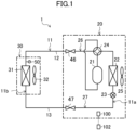
- the outdoor unit (20) includes a gas-side shutoff valve (46), a liquid-side shutoff valve (47), a gas line (26), a liquid line (27), a compressor (21), an outdoor heat exchanger (22), a four-way switching valve (24), an expansion valve (23), and an outdoor fan (25).
- the outdoor circuit (11a) includes the gas-side shutoff valve (46), the liquid-side shutoff valve (47), the compressor (21), the outdoor heat exchanger (22), the four-way switching valve (24), and the expansion valve (23).
- the gas-side shutoff valve (46) and the liquid-side shutoff valve (47) are examples of the shutoff valves (46, 47) of the present disclosure.
- the gas-side shutoff valve (46) and the liquid-side shutoff valve (47) are manually opened and closed by an operator.
- the gas-side shutoff valve (46) is provided on the gas side of the outdoor circuit (11a). Specifically, the gas-side shutoff valve (46) is connected to a gas side end of the outdoor circuit (11a). One end of the first connection pipe (12) is connected to the gas-side shutoff valve (46).
- the liquid-side shutoff valve (47) is provided on the liquid side of the outdoor circuit (11a). The liquid-side shutoff valve (47) is connected to a liquid side end of the outdoor circuit (11a).
- the gas-side shutoff valve (46) and the liquid-side shutoff valve (47) are always open except when a pump-down operation to be described later is performed or when the indoor unit (30) is detached.
- the gas-side shutoff valve (46) and the liquid-side shutoff valve (47) may be collectively referred to as the “shutoff valves (46, 47)."
- the gas line (26) and the liquid line (27) form the outdoor circuit (11a).
- the gas line (26) is configured as a gas pipe through which the gas refrigerant before condensation or heat dissipation in the outdoor heat exchanger (22) flows.
- One end of the gas line (26) is connected to a gas side end of the outdoor heat exchanger (22).
- the gas-side shutoff valve (46) is connected to the other end of the gas line (26).
- the four-way switching valve (24) and the compressor (21) are connected to the gas line (26).
- the liquid line (27) is configured as a liquid pipe through which the liquid refrigerant after condensation or heat dissipation in the outdoor heat exchanger (22) flows.
- One end of the liquid line (27) is connected to a liquid end of the outdoor heat exchanger (22).
- the liquid-side shutoff valve (47) is connected to the other end of the liquid line (27).
- the expansion valve (23) is connected to the liquid line (27).
- the compressor (21) compresses sucked refrigerant.
- the compressor (21) discharges the compressed refrigerant.
- the compressor (21) is, for example, a rotary compressor of a scroll type, an oscillating piston type, a rolling piston type, or a screw type.
- the compressor (21) is configured to have a variable operation frequency (number of rotations) by an inverter device.
- the outdoor heat exchanger (22) is an example of a heat source heat exchanger (22) of the present disclosure.
- the outdoor heat exchanger (22) is a fin-and-tube air heat exchanger.
- the outdoor heat exchanger (22) allows heat exchange between refrigerant flowing therein and outdoor air.
- the outdoor fan (25) is disposed outdoors near the outdoor heat exchanger (22).
- the outdoor fan (25) of this example is a propeller fan.
- the outdoor fan (25) creates an air flow passing through the outdoor heat exchanger (22).
- the four-way switching valve (24) changes the flow path in the refrigerant circuit (11) so as to switch between a first refrigeration cycle that is a cooling cycle and a second refrigeration cycle that is a heating cycle.
- the four-way switching valve (24) reverses the flow of the refrigerant in the refrigerant circuit (11).
- the four-way switching valve (24) switches between a first state indicated by solid lines in FIG. 1 and a second state indicated by broken lines in FIG. 1 .
- the four-way switching valve (24) in the first state makes a discharge side of the compressor (21) and a gas side of the outdoor heat exchanger (22) communicate with each other, and simultaneously makes a suction side of the compressor (21) and a gas side of an indoor heat exchanger (31) communicate with each other.
- the four-way switching valve (24) in the second state makes the discharge side of the compressor (21) and the gas side of the indoor heat exchanger (31) communicate with each other, and simultaneously makes the suction side of the compressor (21) and the gas side of the outdoor heat exchanger (22) communicate with each other.
- the expansion valve (23) decompresses the refrigerant.
- the expansion valve (23) is arranged between the liquid-side shutoff valve (47) and the outdoor heat exchanger (22) in the outdoor circuit (11a).
- the expansion valve (23) is an electronic expansion valve whose opening degree is adjustable.
- the indoor unit (30) is installed in the indoor space. As illustrated in FIG. 1 , the indoor unit (30) includes the indoor heat exchanger (31), an indoor fan (32), and a pressure sensor (50).
- the indoor heat exchanger (31) is an example of a utilization heat exchanger (31) of the present disclosure.
- the indoor heat exchanger (31) is connected to the indoor circuit (11b).
- the indoor heat exchanger (31) exchanges heat between the refrigerant and indoor air.
- the indoor heat exchanger (31) is a fin-and-tube heat exchanger.
- the indoor fan (32) is a crossflow fan configured to transfer indoor air. The air transferred by the indoor fan (32) passes through the indoor heat exchanger (31).
- the pressure sensor (50) detects the pressure of the refrigerant in the indoor circuit (11b). Specifically, the pressure sensor (50) is provided on a refrigerant pipe between the gas-side shutoff valve (46) and the indoor heat exchanger (31) in the indoor circuit (11b). The pressure sensor (50) detects the pressure of the refrigerant on the gas side of the indoor heat exchanger (31).
- the pressure sensor (50) is of a capacitive type, for example.
- the pressure sensor (50) includes a sensor section and a signal processor section, which are not shown.
- the sensor section is a variable capacitor, and changes the capacitance in accordance with the refrigerant pressure.
- the signal processor section converts the capacitance into a voltage value, and transmits (outputs) the voltage value to the control unit (100) to be described later.
- the air conditioning system (1) includes a notification device (60).
- the notification device (60) of this example is a speaker.
- the notification device (60) is provided in the casing of the indoor unit (30).
- the notification device (60) gives various alarms.
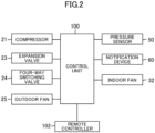
- the air conditioning system (1) includes the control unit (100).
- the control unit (100) includes a microcontroller unit (MCU), an electric circuit, and an electronic circuit.
- the MCU includes a central processing unit (CPU), a memory, and a communication interface.
- the memory stores various programs to be executed by the CPU.
- the control unit (100) is provided on a control board (not shown) of the indoor unit (30).
- the control unit (100) is connected to various devices of the air conditioning system (1) via a wired or wireless communication line.
- the control unit (100) controls operations of various devices of the air conditioning system (1) based on a received command. For example, the control unit (100) controls the various devices of the air conditioning system (1) so that a heating operation is performed.
- the air conditioning system (1) includes a remote controller (102).
- the remote controller (102) is connected to the control unit (100) via a wired or wireless communication line.
- the remote controller (102) outputs a predetermined command to the control unit (100) based on a user's operation.
- the air conditioning system (1) of this embodiment switches between a cooling operation and a heating operation.
- control unit (100) sets the four-way switching valve (24) in the first state.
- control unit (100) operates the compressor (21), the outdoor fan (25), and the indoor fan (32), and adjusts the opening degree of the expansion valve (23).
- the refrigerant circuit (11) during the cooling operation performs a refrigeration cycle (cooling cycle) in which the outdoor heat exchanger (22) functions as a radiator and the indoor heat exchanger (31) functions as an evaporator.
- control unit (100) sets the four-way switching valve (24) in the second state.
- control unit (100) operates the compressor (21), the outdoor fan (25), and the indoor fan (32), and adjusts the opening degree of the expansion valve (23).
- the refrigerant circuit (11) during the heating operation performs a refrigeration cycle (heating cycle) in which the indoor heat exchanger (31) functions as a radiator and the outdoor heat exchanger (22) functions as an evaporator.
- the air conditioning system (1) performs a pump-down operation.
- the pump-down operation is an operation for moving the refrigerant in the indoor circuit (11b) to the outdoor circuit (11a).
- Closing the gas-side shutoff valve (46) and the liquid-side shutoff valve (47) after the end of the pump-down operation (after the amount of the refrigerant in the indoor circuit (11b) becomes substantially equal to zero) restricts the flow of the refrigerant from the outdoor circuit (11a) into the indoor circuit (11b), thereby making it possible to detach the indoor unit (30) safely.
- the gas-side shutoff valve (46) or the liquid-side shutoff valve (47) may flow from the outdoor circuit (11a) into the indoor circuit (11b). If the indoor unit (30) is detached in this state, the refrigerant that has leaked from the gas-side shutoff valve (46) or the liquid-side shutoff valve (47) may flow into the indoor space.
- a flammable refrigerant such as a highly flammable refrigerant, such as propane, may cause ignition in the indoor space.
- shutoff valve (46) and the liquid-side shutoff valve (47) need to be fully closed after the end of pump-down operation. However, determining whether the shutoff valves (46, 47) are open or closed has not been discussed.
- Step S1 the pump-down operation is started. Specifically, when a command for performing the pump-down operation is transmitted from the remote controller (102) to the control unit (100) by an operator's operation, the control unit (100) that has received the command switches the four-way switching valve (24) to the first state, and starts operation of the compressor (21). In addition, the control unit (100) opens the expansion valve (23) fully. In this manner, the cooling operation is performed during the pump-down operation.
- Step S2 in a situation where the gas-side shutoff valve (46) and the liquid-side shutoff valve (47) are open, only the liquid-side shutoff valve (47) is closed based on the operator's work. This allows the refrigerant in the indoor circuit (11b) to be sucked by the compressor (21) and move to the outdoor circuit (11a).
- Step S3 the operator closes the gas-side shutoff valve (46) in the state in which the liquid-side shutoff valve (47) is closed.
- Step S3 is started after a certain time has elapsed since Step S2. The certain time may be at least a period or longer during which the entirety of the refrigerant in the indoor circuit (11b) is assumed to have been collected into the outdoor circuit (11a).
- the process from Steps S1 to S3 is referred to as the "pump-down operation.”
- Step S4 the pump-down operation stops. Specifically, when a command for stopping the pump-down operation is transmitted from the remote controller (102) to the control unit (100) by the operator's operation, the control unit (100) that has received the command stops the operation of the compressor (21).
- Step S5 the control unit (100) determines whether the gas-side shutoff valve (46) and the liquid-side shutoff valve (47) are open or closed, based on changes in the refrigerant pressure in the indoor circuit (11b). Step S5 will be described in detail later. If it is determined that at least one of the gas-side shutoff valve (46) or the liquid-side shutoff valve (47) is in the open state ("YES" in Step S5), Step S6 is executed. If it is determined that the gas-side shutoff valve (46) and the liquid-side shutoff valve (47) are in the closed state ("NO" in Step S5), Step S9 is executed.
- the control unit (100) does not make a determination as to the opening or closing of the valve for each of the gas-side shutoff valve (46) and the liquid-side shutoff valve (47).
- the shutoff valves are determined to be in the open state, at least one of the gas-side shutoff valve (46) or the liquid-side shutoff valve (47) is in the open state.
- the open state is a state in which even though the operator closes the gas-side shutoff valve (46) and the liquid-side shutoff valve (47) in S2 and S3, the valves are not completely closed and slightly open.
- Step S6 the control unit (100) actuates the notification device (60).
- the notification device (60) gives a first alarm sound.
- the first alarm sound may be a simple digital sound or a voice reporting that the shutoff valves (46, 47) are not fully closed.
- the first alarm sound allows the operator to recognize that at least one of the gas-side shutoff valve (46) or the liquid-side shutoff valve (47) is not fully closed and that the refrigerant is leaking to the indoor circuit (11b).
- Step S7 the gas-side shutoff valve (46) is opened by the operator's work, and the liquid-side shutoff valve (47) is further tightened (additionally tightened).
- Step S8 the control unit (100) starts the pump-down operation. Specifically, a command for performing the pump-down operation is transmitted from the remote controller (102) to the control unit (100) by the operator's operation. After the end of Step S8, Step S3 is executed again.
- Step S9 the control unit (100) actuates the notification device (60).
- the notification device (60) gives a second alarm sound.
- the second alarm sound may be a simple digital sound or a voice reporting that the shutoff valves (46, 47) have been closed.
- the second alarm sound allows the operator to recognize that the gas-side shutoff valve (46) and the liquid-side shutoff valve (47) are fully closed and that the refrigerant is not leaking to the indoor circuit (11b).
- Step S5 will be described in detail.
- the control unit (100) determines whether the shutoff valves (46, 47) are open or closed, based on a first pressure P1 that is the refrigerant pressure at a first point in time and a second pressure P2 that is the refrigerant pressure at a second point in time later than the first point in time.
- the period from the first point in time to the second point in time is, for example, two to five minutes.
- the first point in time is when a predetermined standby period has elapsed since the end of the pump-down operation.
- the standby period is, for example, about 10 seconds.
- the control unit (100) acquires the first pressure P1 at a time (first point in time) when 10 seconds have elapsed since the end of the pump-down operation (the end of Step S4), and acquires the second pressure P2 at a time (second point in time) when three minutes have elapsed since the acquisition of the first pressure P1.
- the control unit (100) determines that the shutoff valves (46, 47) are in the open state. On the other hand, if the second pressure P2 is equal to or lower than the first pressure P1, the control unit (100) determines that the shutoff valves (46, 47) are in the closed state.
- Step S11 the control unit (100) determines whether the standby period has elapsed. In other words, the control unit (100) determines whether the time that has elapsed since the end of the pump-down operation has reached the first point in time. If it is determined that the time has reached the first point in time ("YES" in Step S11), Step S12 is executed. If it is determined that the time has not reached the first point in time ("NO" in Step S11), Step S11 is executed again.
- Step S12 the control unit (100) acquires a pressure value from the pressure sensor (50). This pressure value is the first pressure P1.
- the first pressure P1 is stored in a memory.
- Step S13 the control unit (100) determines whether the time has reached the second point in time. If it is determined that the time has reached the second point in time ("YES" in Step S13), Step S14 is executed. If it is determined that the time has not reached the second point in time ("NO" in Step S13), Step S13 is executed again.
- Step S14 the control unit (100) acquires a pressure value from the pressure sensor (50). This pressure value is the second pressure P2.
- the second pressure P2 is stored in the memory.
- Step S15 the control unit (100) determines whether the second pressure P2 acquired in Step S14 is higher than the first pressure P1 acquired in Step S12. If it is determined that the second pressure P2 is higher than the first pressure P1 ("YES" in Step S15), the control unit (100) determines whether the second pressure P2 acquired in Step S14 is higher than the first pressure P1 ("YES" in Step S15).
- Step S16 determines that the shutoff valves (46, 47) are open. If it is determined that the second pressure P2 is equal to or lower than the first pressure P1 ("NO" in Step S15), the control unit (100) determines that the shutoff valves (46, 47) are closed (Step S17).
- shutoff valves (46, 47) are open or closed is determined based on changes in the refrigerant pressure in the indoor circuit (11b) after the end of the pump-down operation that allows the refrigerant in the indoor circuit (11b) to move to the outdoor circuit (11a).
- the refrigerant in the refrigerant circuit (11) can be kept from decreasing, it is possible to save time and effort checking a charge amount of the refrigerant in the refrigerant circuit (11) and adding a refrigerant in a case of shortage of the charge amount of the refrigerant.
- the user is notified that the shutoff valves (46, 47) are closed and that the shutoff valves (46, 47) are open, based on the determination as to whether the shutoff valves (46, 47) are open or closed.
- the notification device (60) gives the second alarm sound indicating that the shutoff valves (46, 47) are closed and the first alarm sound indicating that the shutoff valves (46, 47) are open.
- the user can easily grasp whether the shutoff valves (46, 47) are open or closed, based on which of the first alarm sound or the second alarm sound is given after the end of the pump-down operation.
- the pressure sensor (50) detects the refrigerant pressure between the gas-side shutoff valve (46) and the indoor heat exchanger (31).
- a single pressure sensor (50) can be used to determine whether the shutoff valves are open or closed after the end of the pump-down operation as well as to determine the high pressure during the usual heating operation. It is thus possible to use the pressure sensor (50) effectively.
- the refrigerant is a flammable refrigerant. If a flammable refrigerant leaks to the indoor circuit (11b) after the end of the pump-down operation, the leaked refrigerant cause ignition in the indoor space in detaching the indoor unit (30). However, in the air conditioning system (1) of this embodiment, it is possible to keep the refrigerant from leaking and therefore possible to reduce the risk of such ignition.
- an air conditioning system (1) of a first variation includes a temperature sensor (70) configured to detect the refrigerant temperature in an indoor circuit (11b).
- the temperature sensor (70) is provided between a gas-side shutoff valve (46) and an indoor heat exchanger (31) in the indoor circuit (11b).
- the temperature sensor (70) detects the temperature of the refrigerant on the gas side of the indoor heat exchanger (31).
- the ratio of the refrigerant pressure to the refrigerant temperature in the indoor circuit (11b) (specifically, on the gas side of the indoor heat exchanger (31)) is referred to as the "ratio P/T.”
- a control unit (100) of this example acquires the pressure value (first pressure P1) detected by a pressure sensor (50) and the temperature value (first temperature T1) detected by the temperature sensor (70) at the time when a standby period has elapsed since the end of a pump-down operation (at the first point in time).
- the ratio of the refrigerant pressure to the refrigerant temperature at this time is referred to as the "first ratio (P1/T1)."
- the control unit (100) of this example acquires the pressure value (second pressure P2) detected by the pressure sensor (50) and the temperature value (second temperature T2) detected by the temperature sensor (70) at the second point in time.
- the ratio of the refrigerant pressure to the refrigerant temperature at this time is referred to as the "second ratio (P2/T2)."
- the control unit (100) determines which of the first ratio (P1/T1) or the second ratio (P2/T2) is higher in Step S5 of the flowchart of the above embodiment (see FIG. 3 ). A determination as to whether shutoff valves (46, 47) of this example are open or closed will be described below with reference to FIG. 6 . Steps other than Step S5 are the same as those of the above embodiment.
- Step S21 the control unit (100) determines whether the time from the end of the pump-down operation has reached the first point in time. If it is determined that the time has reached the first point in time ("YES" in Step S21), Step S22 is executed. If it is determined that the time has not reached the first point in time ("NO" in Step S21), Step S21 is executed again.
- Step S22 the control unit (100) acquires a pressure value from the pressure sensor (50). This pressure value is the first pressure P1.
- the first pressure P1 is stored in a memory.
- Step S23 the control unit (100) acquires a temperature value from the temperature sensor (70). This temperature value is the first temperature T1.
- the first temperature T1 is stored in the memory.
- Step S24 the control unit (100) determines whether the time has reached the second point in time. If it is determined that the time has reached the second point in time ("YES" in Step S24), Step S25 is executed. If it is determined that the time has not reached the second point in time ("NO" in Step S24), Step S24 is executed again.
- Step S25 the control unit (100) acquires a pressure value from the pressure sensor (50). This pressure value is the second pressure P2.
- the second pressure P2 is stored in the memory.
- Step S26 the control unit (100) acquires a temperature value from the temperature sensor (70). This temperature value is the second temperature T2.
- the second temperature T2 is stored in the memory.
- Step S27 the control unit (100) determines whether the second ratio (P2/T2) acquired in Steps S25 and S26 is higher than the first ratio (P1/T1) acquired in Steps S22 and S23. If it is determined that the second ratio is higher than the first ratio ("YES" in Step S27), the control unit (100) determines that the shutoff valves (46, 47) are open (Step S28). If it is determined that the second ratio is equal to or lower than the first ratio ("NO" in Step S27), the control unit (100) determines that the shutoff valves (46, 47) are closed (Step S29).
- a control unit (100) determines whether the shutoff valves (46, 47) are open or closed based on the refrigerant pressure in the indoor circuit (11b) after the end of a pump-down operation. Specifically, if the refrigerant pressure P at a predetermined point in time after the end of the pump-down operation is higher than a first predetermined value, the control unit (100) of this example determines that the shutoff valves (46, 47) are open. If the refrigerant pressure P at this point in time is equal to or lower than the first predetermined value, the control unit (100) determines that the shutoff valves (46, 47) are closed.
- the control unit (100) may determine that the shutoff valves (46, 47) are open if the ratio (P/T) of the refrigerant pressure to the refrigerant temperature at a predetermined point in time after the end of the pump-down operation is higher than a second predetermined value, and may determine that the shutoff valves (46, 47) are closed if the ratio (P/T) is equal to or lower than the second predetermined value.
- the first predetermined value and the second predetermined value are arbitrary values.
- the control unit (100) acquires a refrigerant pressure, or a ratio of the refrigerant pressure to the refrigerant temperature, at each of the first point in time and the second point in time, but is not limited thereto.
- the control unit (100) may acquire a refrigerant pressure, or the ratio of the refrigerant pressure to the refrigerant temperature, at a third point in time later than the second point in time.
- shutoff valves (46, 47) it is possible to make more accurate determination as to whether the shutoff valves (46, 47) are open or closed and possible to reduce false detection of the opening or closing of the shutoff valves (46, 47), by comparing the refrigerant pressures, or the ratios of the refrigerant pressures to the refrigerant temperatures, at the three points in time, that is, the first point in time, the second point in time, and the third point in time.
- the control unit (100) may acquire the refrigerant pressure or the ratio of the refrigerant pressure to the refrigerant temperature at four or more points in time.
- shutoff valves (46, 47) are open if the second pressure P2 is higher than the first pressure P1, and the difference between P2 and P1 is greater than a predetermined value.
- the shutoff valves (46, 47) are open if the second ratio (P2/T2) is higher than the first ratio (P1/T1), and the difference between the second ratio and the first ratio is greater than a predetermined value. Setting these predetermined values can reduce false detection of the opening or closing the shutoff valves (46, 47).
- the first point in time may be the time when the pump-down operation is ended. That is, the control unit (100) may acquire the first pressure P1 or the first ratio (P1/T1) without setting the standby period.
- the refrigerant pressure, or the refrigerant pressure and the refrigerant temperature, at the first point in time or the second point in time may be acquired based on an operator's operation.
- the air conditioning system (1) does not have to include the pressure sensor (50).
- the air conditioning system (1) may include a temperature sensor (70) configured to detect the refrigerant temperature in the indoor circuit (11b), and the refrigerant pressures (including the first pressure and the second pressure) may be determined based on the refrigerant temperatures.
- the refrigerant may be a fluorocarbon refrigerant, such as R32 and R1234yf, or a non-inflammable hydrofluorocarbon (HFC) refrigerant.
- fluorocarbon refrigerant such as R32 and R1234yf
- HFC non-inflammable hydrofluorocarbon
- control unit (100) may be provided on a control board (not shown) of the outdoor unit (20).
- control unit (100) may be provided on each of the control board of the indoor unit (30) and the control board of the outdoor unit (20) so that these control units (100) operate in cooperation with each other.
- the control board of the indoor unit (30) that has received a value detected by the pressure sensor (50) may transmit the value to the control board of the outdoor unit (20), and the control board of the outdoor unit (20) may determine whether the shutoff valves (46, 47) are open or closed.
- the control unit (100) may be provided on a control board of the remote controller (102).
- the notification device (60) may be a display provided for the remote controller (102).
- the display may indicate that the shutoff valves (46, 47) are not fully closed or that the shutoff valves (46, 47) are closed.
- the present disclosure is useful for an air conditioning system.
Landscapes
- Engineering & Computer Science (AREA)
- Physics & Mathematics (AREA)
- Mechanical Engineering (AREA)
- Thermal Sciences (AREA)
- General Engineering & Computer Science (AREA)
- Air Conditioning Control Device (AREA)
Abstract
Description
- The present disclosure relates to an air conditioning system.
- Patent Document 1 describes an air conditioner configured to isolate an electromagnetic valve and stop a compressor after a predetermined time when the inlet pressure of a compressor becomes equal to or lower than a predetermined value in a pump-down operation.
- Patent Document 1:
Japanese Unexamined Patent Publication No. 2003-161535 - No consideration has been given to the leakage of a refrigerant from a heat source heat exchanger toward a utilization heat exchanger through a shutoff valve after the end of the pump-down operation.
- It is an object of the present disclosure to determine whether or not a refrigerant is leaking through a shutoff valve after the end of a pump-down operation.
- A first aspect of the present disclosure is directed to an air conditioning system including:
- a heat source unit (20) having a heat source circuit (11a) to which a compressor (21) and a heat source heat exchanger (22) are connected; and
- a utilization unit (30) having a utilization circuit (11b) to which a utilization heat exchanger (31) is connected,
- the heat source circuit (11a) and the utilization circuit (11b) being connected to each other via a shutoff valve (46, 47) to form a refrigerant circuit (11) that performs a refrigeration cycle,
- whether the shutoff valve (46, 47) is open or closed being determined based on changes in a refrigerant pressure in the utilization circuit (11b) after an end of a pump-down operation in which a refrigerant in the utilization circuit (11b) is moved to the heat source circuit (11a).
- According to the first aspect, it is possible to check leakage of the refrigerant from the heat source circuit (11a) to the utilization circuit (11b) after the end of the pump-down operation by determining whether the shutoff valve (46, 47) is open or closed.
- A second aspect of the present disclosure is an embodiment of the first aspect. In the second aspect,
it is determined that the shutoff valve (46, 47) is open if a second pressure is higher than a first pressure, where the first pressure is the refrigerant pressure at a first point in time after the end of the pump-down operation, and the second pressure is the refrigerant pressure at a second point in time later than the first point in time. - According to the second aspect, when the second pressure is higher than the first pressure, it is known that the refrigerant has returned to the utilization circuit (11b). This determination enables a grasp of the fact that the shutoff valve (46, 47) is open.
- A third aspect of the present disclosure is an embodiment of the first aspect. In the third aspect,
it is determined that the shutoff valve (46, 47) is open if a second ratio is higher than a first ratio, where the first ratio is a ratio of the refrigerant pressure to a refrigerant temperature in the utilization circuit (11b) at a first point in time after the end of the pump-down operation, and the second ratio is a ratio of the refrigerant pressure to a refrigerant temperature in the utilization circuit (11b) at a second point in time later than the first point in time. - According to the third aspect, the refrigerant temperature is also included in the parameters, which makes it possible to make a more precise determination.
- A fourth aspect of the present disclosure is an embodiment of the first to third aspects. In the fourth aspect,
it is determined that the shutoff valve (46, 47) is closed if a second pressure is equal to or lower than a first pressure, where the first pressure is the refrigerant pressure at a first point in time after the end of the pump-down operation, and the second pressure is the refrigerant pressure at a second point in time later than the first point. - According to the fourth aspect, when the second pressure is equal to or lower than the first pressure, it is known that the refrigerant has not returned to the utilization circuit (11b). This determination enables a grasp of the fact that the shutoff valve (46, 47) is closed.
- A fifth aspect of the present disclosure is an embodiment of the first to third aspects. In the fifth aspect,
it is determined that the shutoff valve (46, 47) is closed if a second ratio is equal to or lower than a first ratio, where the first ratio is a ratio of the refrigerant pressure to a refrigerant temperature in the utilization circuit (11b) at a first point in time after the end of the pump-down operation, and the second ratio is a ratio of the refrigerant pressure to a refrigerant temperature in the utilization circuit (11b) at a second point in time later than the first point in time. - According to the fifth aspect, the refrigerant temperature is also included in the parameters, which makes it possible to make a more precise determination.
- A sixth aspect of the present disclosure is an embodiment of any one of the first to fifth aspects. In the sixth aspect,
a user is notified that the shutoff valve (46, 47) is closed or that the shutoff valve (46, 47) is open, based on the determination as to whether the shutoff valve (46, 47) is open or closed. - According to the sixth aspect, the user can recognize whether the shutoff valve (46, 47) is open or closed.
- A seventh aspect of the present disclosure is an embodiment of any one of the first to sixth aspects. In the seventh aspect,
- the shutoff valve (46, 47) includes a liquid-side shutoff valve (47) provided on a liquid side of the utilization circuit (11b) and a gas-side shutoff valve (46) provided on a gas side of the utilization circuit (11b), and
- the refrigerant pressure indicates a pressure between the gas-side shutoff valve (46) and the utilization heat exchanger (31).
- According to the seventh aspect, the detection of changes in the pressure after the end of the pump-down operation and the detection of the high pressure in a heating operation can be performed.
- An eighth aspect of the present disclosure is an embodiment of any one of the first to seventh aspects. In the eighth aspect,
the refrigerant is a flammable refrigerant. - According to the eighth aspect, a flammable refrigerant can reduce the risk of ignition due to leakage into the room.
- A ninth aspect of the present disclosure is directed to a method for checking whether shutoff valves (46, 47) are in an open state or a closed state after an end of a pump-down operation of an air conditioning system. The air conditioning system includes:
- a heat source unit (20) having a heat source circuit (11a) including a compressor (21) and a heat source heat exchanger (22); and
- a utilization unit (30) having a utilization circuit (11b) including a utilization heat exchanger (31),
- the heat source circuit (11a) and the utilization circuit (11b) being connected to each other via the shutoff valves (46, 47) to form a refrigerant circuit (11) that performs a refrigeration cycle,
- the shutoff valves (46, 47) including a liquid-side shutoff valve (47) provided on a liquid side of the heat source circuit (11a) and a gas-side shutoff valve (46) provided on a gas side of the heat source circuit (11a), the method including:
- starting the pump-down operation;
- closing the liquid-side shutoff valve (47);
- closing the gas-side shutoff valve (46);
- ending the pump-down operation; and
- determining whether the shutoff valves (46, 47) are open or closed based on changes in a refrigerant pressure in the utilization circuit (11b) or a ratio of the refrigerant pressure to a refrigerant temperature in the utilization circuit (11b).
-
-
FIG. 1 is a piping system diagram schematically illustrating an air conditioning system of an embodiment. -
FIG. 2 is a block diagram of the air conditioning system. -
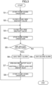
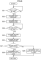
FIG. 3 is a flowchart showing the procedure of a method for checking whether shutoff valves are open or closed. -
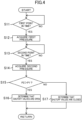
FIG. 4 is a flowchart for a determination of whether the shutoff valves are open or closed. -
FIG. 5 is a block diagram illustrating an air conditioning system according to a variation and corresponding toFIG. 2 . -
FIG. 6 is a flowchart for a determination of whether the shutoff valves are open or closed according to a variation. - Embodiments of the present invention will be described in detail below with reference to the drawings. The following embodiments are merely exemplary ones in nature, and are not intended to limit the scope, application, or use of the invention. Features of the embodiments, variations, and other examples described below can be combined or partially substituted within the range where the present invention can be embodied.
- As illustrated in
FIGS. 1 and2 , an air conditioning system (1) of this embodiment includes an outdoor unit (20), an indoor unit (30), connection pipes (12, 13), and a control unit (100). The outdoor unit (20) is an example of a heat source unit (20) of the present disclosure. The indoor unit (30) is an example of a utilization unit (30) of the present disclosure. The air conditioning system (1) controls the temperature of air in an indoor space. The air conditioning system (1) switches among a cooling operation, a heating operation, and a pump-down operation. - The outdoor unit (20) and the indoor unit (30) are connected to each other via the connection pipes (12, 13). This connection forms a refrigerant circuit (11) which is a closed circuit.
- The refrigerant circuit (11) performs a refrigeration cycle. The refrigerant circuit (11) is formed by an outdoor circuit (11a) and an indoor circuit (11b) which are connected together via shutoff valves (46, 47) to be described later. The outdoor circuit (11a) is provided in the outdoor unit (20). The indoor circuit (11b) is provided in the indoor unit (30). The outdoor circuit (11a) is an example of a heat source circuit (11a) of the present disclosure. The indoor circuit (11b) is an example of a utilization circuit (11b) of the present disclosure.
- The refrigerant circuit (11) is filled with a flammable natural refrigerant. The refrigerant in this embodiment is propane (R290), which is a highly flammable natural refrigerant. The natural refrigerant is a refrigerant having an ozone depletion potential of zero, a low global warming potential, and a low environmental load.
- The flammable refrigerant with which the refrigerant circuit (11) is filled may be other than propane. The flammable refrigerant with which the refrigerant circuit (11) is filled may be, for example, ammonia (R717), which is a natural refrigerant. Alternatively, the flammable refrigerant with which the refrigerant circuit (11) is filled may be methane (R50), ethane (R170), butane (R600), or isobutane (R600a), which is a highly flammable natural refrigerant.
- A first connection pipe (12) and a second connection pipe (13) are examples of the connection pipes (12, 13) of the present disclosure. The first connection pipe (12) and the second connection pipe (13) connect the indoor unit (30) and the outdoor unit (20) to each other. The first connection pipe (12) is a gas pipe, and the second connection pipe (13) is a liquid pipe.
- The first connection pipe (12) has one end connected to a gas end of the indoor circuit (11b), and the other end connected to a gas end of the outdoor circuit (11a). The second connection pipe (13) has one end connected to a liquid end of the indoor circuit (11b), and the other end connected to a liquid end of the outdoor circuit (11a).
- The outdoor unit (20) is placed outdoors. The outdoor unit (20) includes a gas-side shutoff valve (46), a liquid-side shutoff valve (47), a gas line (26), a liquid line (27), a compressor (21), an outdoor heat exchanger (22), a four-way switching valve (24), an expansion valve (23), and an outdoor fan (25). Specifically, the outdoor circuit (11a) includes the gas-side shutoff valve (46), the liquid-side shutoff valve (47), the compressor (21), the outdoor heat exchanger (22), the four-way switching valve (24), and the expansion valve (23).
- The gas-side shutoff valve (46) and the liquid-side shutoff valve (47) are examples of the shutoff valves (46, 47) of the present disclosure. The gas-side shutoff valve (46) and the liquid-side shutoff valve (47) are manually opened and closed by an operator. The gas-side shutoff valve (46) is provided on the gas side of the outdoor circuit (11a). Specifically, the gas-side shutoff valve (46) is connected to a gas side end of the outdoor circuit (11a). One end of the first connection pipe (12) is connected to the gas-side shutoff valve (46). The liquid-side shutoff valve (47) is provided on the liquid side of the outdoor circuit (11a). The liquid-side shutoff valve (47) is connected to a liquid side end of the outdoor circuit (11a). One end of the second connection pipe (13) is connected to the liquid-side shutoff valve (47). The gas-side shutoff valve (46) and the liquid-side shutoff valve (47) are always open except when a pump-down operation to be described later is performed or when the indoor unit (30) is detached. In the following description, the gas-side shutoff valve (46) and the liquid-side shutoff valve (47) may be collectively referred to as the "shutoff valves (46, 47)."
- The gas line (26) and the liquid line (27) form the outdoor circuit (11a). The gas line (26) is configured as a gas pipe through which the gas refrigerant before condensation or heat dissipation in the outdoor heat exchanger (22) flows. One end of the gas line (26) is connected to a gas side end of the outdoor heat exchanger (22). The gas-side shutoff valve (46) is connected to the other end of the gas line (26). The four-way switching valve (24) and the compressor (21) are connected to the gas line (26).
- The liquid line (27) is configured as a liquid pipe through which the liquid refrigerant after condensation or heat dissipation in the outdoor heat exchanger (22) flows. One end of the liquid line (27) is connected to a liquid end of the outdoor heat exchanger (22). The liquid-side shutoff valve (47) is connected to the other end of the liquid line (27). The expansion valve (23) is connected to the liquid line (27).
- The compressor (21) compresses sucked refrigerant. The compressor (21) discharges the compressed refrigerant. The compressor (21) is, for example, a rotary compressor of a scroll type, an oscillating piston type, a rolling piston type, or a screw type. The compressor (21) is configured to have a variable operation frequency (number of rotations) by an inverter device.
- The outdoor heat exchanger (22) is an example of a heat source heat exchanger (22) of the present disclosure. The outdoor heat exchanger (22) is a fin-and-tube air heat exchanger. The outdoor heat exchanger (22) allows heat exchange between refrigerant flowing therein and outdoor air.
- The outdoor fan (25) is disposed outdoors near the outdoor heat exchanger (22). The outdoor fan (25) of this example is a propeller fan. The outdoor fan (25) creates an air flow passing through the outdoor heat exchanger (22).
- The four-way switching valve (24) changes the flow path in the refrigerant circuit (11) so as to switch between a first refrigeration cycle that is a cooling cycle and a second refrigeration cycle that is a heating cycle. The four-way switching valve (24) reverses the flow of the refrigerant in the refrigerant circuit (11). The four-way switching valve (24) switches between a first state indicated by solid lines in
FIG. 1 and a second state indicated by broken lines inFIG. 1 . The four-way switching valve (24) in the first state makes a discharge side of the compressor (21) and a gas side of the outdoor heat exchanger (22) communicate with each other, and simultaneously makes a suction side of the compressor (21) and a gas side of an indoor heat exchanger (31) communicate with each other. The four-way switching valve (24) in the second state makes the discharge side of the compressor (21) and the gas side of the indoor heat exchanger (31) communicate with each other, and simultaneously makes the suction side of the compressor (21) and the gas side of the outdoor heat exchanger (22) communicate with each other. - The expansion valve (23) decompresses the refrigerant. The expansion valve (23) is arranged between the liquid-side shutoff valve (47) and the outdoor heat exchanger (22) in the outdoor circuit (11a). The expansion valve (23) is an electronic expansion valve whose opening degree is adjustable.
- The indoor unit (30) is installed in the indoor space. As illustrated in
FIG. 1 , the indoor unit (30) includes the indoor heat exchanger (31), an indoor fan (32), and a pressure sensor (50). - The indoor heat exchanger (31) is an example of a utilization heat exchanger (31) of the present disclosure. The indoor heat exchanger (31) is connected to the indoor circuit (11b).
- The indoor heat exchanger (31) exchanges heat between the refrigerant and indoor air. The indoor heat exchanger (31) is a fin-and-tube heat exchanger. The indoor fan (32) is a crossflow fan configured to transfer indoor air. The air transferred by the indoor fan (32) passes through the indoor heat exchanger (31).
- The pressure sensor (50) detects the pressure of the refrigerant in the indoor circuit (11b). Specifically, the pressure sensor (50) is provided on a refrigerant pipe between the gas-side shutoff valve (46) and the indoor heat exchanger (31) in the indoor circuit (11b). The pressure sensor (50) detects the pressure of the refrigerant on the gas side of the indoor heat exchanger (31).
- The pressure sensor (50) is of a capacitive type, for example. The pressure sensor (50) includes a sensor section and a signal processor section, which are not shown. The sensor section is a variable capacitor, and changes the capacitance in accordance with the refrigerant pressure. The signal processor section converts the capacitance into a voltage value, and transmits (outputs) the voltage value to the control unit (100) to be described later.
- The air conditioning system (1) includes a notification device (60). The notification device (60) of this example is a speaker. The notification device (60) is provided in the casing of the indoor unit (30). The notification device (60) gives various alarms.
- The air conditioning system (1) includes the control unit (100). The control unit (100) includes a microcontroller unit (MCU), an electric circuit, and an electronic circuit. The MCU includes a central processing unit (CPU), a memory, and a communication interface. The memory stores various programs to be executed by the CPU.
The control unit (100) is provided on a control board (not shown) of the indoor unit (30). The control unit (100) is connected to various devices of the air conditioning system (1) via a wired or wireless communication line. The control unit (100) controls operations of various devices of the air conditioning system (1) based on a received command. For example, the control unit (100) controls the various devices of the air conditioning system (1) so that a heating operation is performed. - The air conditioning system (1) includes a remote controller (102). The remote controller (102) is connected to the control unit (100) via a wired or wireless communication line. The remote controller (102) outputs a predetermined command to the control unit (100) based on a user's operation.
- The air conditioning system (1) of this embodiment switches between a cooling operation and a heating operation.
- In the cooling operation, the control unit (100) sets the four-way switching valve (24) in the first state. In the cooling operation, the control unit (100) operates the compressor (21), the outdoor fan (25), and the indoor fan (32), and adjusts the opening degree of the expansion valve (23).
- The refrigerant circuit (11) during the cooling operation performs a refrigeration cycle (cooling cycle) in which the outdoor heat exchanger (22) functions as a radiator and the indoor heat exchanger (31) functions as an evaporator.
- In the heating operation, the control unit (100) sets the four-way switching valve (24) in the second state. In the heating operation, the control unit (100) operates the compressor (21), the outdoor fan (25), and the indoor fan (32), and adjusts the opening degree of the expansion valve (23).
- The refrigerant circuit (11) during the heating operation performs a refrigeration cycle (heating cycle) in which the indoor heat exchanger (31) functions as a radiator and the outdoor heat exchanger (22) functions as an evaporator.
- The air conditioning system (1) performs a pump-down operation. The pump-down operation is an operation for moving the refrigerant in the indoor circuit (11b) to the outdoor circuit (11a). Closing the gas-side shutoff valve (46) and the liquid-side shutoff valve (47) after the end of the pump-down operation (after the amount of the refrigerant in the indoor circuit (11b) becomes substantially equal to zero) restricts the flow of the refrigerant from the outdoor circuit (11a) into the indoor circuit (11b), thereby making it possible to detach the indoor unit (30) safely.
- However, if the gas-side shutoff valve (46) or the liquid-side shutoff valve (47) is not fully closed after the end of pump-down operation, the refrigerant may flow from the outdoor circuit (11a) into the indoor circuit (11b). If the indoor unit (30) is detached in this state, the refrigerant that has leaked from the gas-side shutoff valve (46) or the liquid-side shutoff valve (47) may flow into the indoor space. In particular, a flammable refrigerant such as a highly flammable refrigerant, such as propane, may cause ignition in the indoor space.
- Thus, the gas-side shutoff valve (46) and the liquid-side shutoff valve (47) need to be fully closed after the end of pump-down operation. However, determining whether the shutoff valves (46, 47) are open or closed has not been discussed.
- To address the above problem, in the air conditioning system (1) of this embodiment, whether the gas-side shutoff valve (46) and the liquid-side shutoff valve (47) after the end of the pump-down operation are open or closed is checked. A checking method will be described below with reference to
FIG. 3 . - In Step S1, the pump-down operation is started. Specifically, when a command for performing the pump-down operation is transmitted from the remote controller (102) to the control unit (100) by an operator's operation, the control unit (100) that has received the command switches the four-way switching valve (24) to the first state, and starts operation of the compressor (21). In addition, the control unit (100) opens the expansion valve (23) fully. In this manner, the cooling operation is performed during the pump-down operation.
- In Step S2, in a situation where the gas-side shutoff valve (46) and the liquid-side shutoff valve (47) are open, only the liquid-side shutoff valve (47) is closed based on the operator's work. This allows the refrigerant in the indoor circuit (11b) to be sucked by the compressor (21) and move to the outdoor circuit (11a).
- In Step S3, the operator closes the gas-side shutoff valve (46) in the state in which the liquid-side shutoff valve (47) is closed. Step S3 is started after a certain time has elapsed since Step S2. The certain time may be at least a period or longer during which the entirety of the refrigerant in the indoor circuit (11b) is assumed to have been collected into the outdoor circuit (11a). The process from Steps S1 to S3 is referred to as the "pump-down operation."
- In Step S4, the pump-down operation stops. Specifically, when a command for stopping the pump-down operation is transmitted from the remote controller (102) to the control unit (100) by the operator's operation, the control unit (100) that has received the command stops the operation of the compressor (21).
- In Step S5, the control unit (100) determines whether the gas-side shutoff valve (46) and the liquid-side shutoff valve (47) are open or closed, based on changes in the refrigerant pressure in the indoor circuit (11b). Step S5 will be described in detail later. If it is determined that at least one of the gas-side shutoff valve (46) or the liquid-side shutoff valve (47) is in the open state ("YES" in Step S5), Step S6 is executed. If it is determined that the gas-side shutoff valve (46) and the liquid-side shutoff valve (47) are in the closed state ("NO" in Step S5), Step S9 is executed.
- Here, the control unit (100) does not make a determination as to the opening or closing of the valve for each of the gas-side shutoff valve (46) and the liquid-side shutoff valve (47). When the shutoff valves are determined to be in the open state, at least one of the gas-side shutoff valve (46) or the liquid-side shutoff valve (47) is in the open state. The open state is a state in which even though the operator closes the gas-side shutoff valve (46) and the liquid-side shutoff valve (47) in S2 and S3, the valves are not completely closed and slightly open.
- In Step S6, the control unit (100) actuates the notification device (60). The notification device (60) gives a first alarm sound. The first alarm sound may be a simple digital sound or a voice reporting that the shutoff valves (46, 47) are not fully closed. The first alarm sound allows the operator to recognize that at least one of the gas-side shutoff valve (46) or the liquid-side shutoff valve (47) is not fully closed and that the refrigerant is leaking to the indoor circuit (11b).
- In Step S7, the gas-side shutoff valve (46) is opened by the operator's work, and the liquid-side shutoff valve (47) is further tightened (additionally tightened).
- In Step S8, the control unit (100) starts the pump-down operation. Specifically, a command for performing the pump-down operation is transmitted from the remote controller (102) to the control unit (100) by the operator's operation. After the end of Step S8, Step S3 is executed again.
- In Step S9, the control unit (100) actuates the notification device (60). The notification device (60) gives a second alarm sound. The second alarm sound may be a simple digital sound or a voice reporting that the shutoff valves (46, 47) have been closed. The second alarm sound allows the operator to recognize that the gas-side shutoff valve (46) and the liquid-side shutoff valve (47) are fully closed and that the refrigerant is not leaking to the indoor circuit (11b).
- Next, Step S5 will be described in detail.
- After the end of the pump-down operation (the end of Step S4), the control unit (100) determines whether the shutoff valves (46, 47) are open or closed, based on a first pressure P1 that is the refrigerant pressure at a first point in time and a second pressure P2 that is the refrigerant pressure at a second point in time later than the first point in time. The period from the first point in time to the second point in time is, for example, two to five minutes.
- In this embodiment, the first point in time is when a predetermined standby period has elapsed since the end of the pump-down operation. The standby period is, for example, about 10 seconds. The control unit (100) acquires the first pressure P1 at a time (first point in time) when 10 seconds have elapsed since the end of the pump-down operation (the end of Step S4), and acquires the second pressure P2 at a time (second point in time) when three minutes have elapsed since the acquisition of the first pressure P1.
- If the first pressure P1 and the second pressure P2 are compared to find out that the second pressure P2 is higher than the first pressure P1, the control unit (100) determines that the shutoff valves (46, 47) are in the open state. On the other hand, if the second pressure P2 is equal to or lower than the first pressure P1, the control unit (100) determines that the shutoff valves (46, 47) are in the closed state. The series of flows described above will be described with reference to
FIG. 4 . - In Step S11, the control unit (100) determines whether the standby period has elapsed. In other words, the control unit (100) determines whether the time that has elapsed since the end of the pump-down operation has reached the first point in time. If it is determined that the time has reached the first point in time ("YES" in Step S11), Step S12 is executed. If it is determined that the time has not reached the first point in time ("NO" in Step S11), Step S11 is executed again.
- In Step S12, the control unit (100) acquires a pressure value from the pressure sensor (50). This pressure value is the first pressure P1. The first pressure P1 is stored in a memory.
- In Step S13, the control unit (100) determines whether the time has reached the second point in time. If it is determined that the time has reached the second point in time ("YES" in Step S13), Step S14 is executed. If it is determined that the time has not reached the second point in time ("NO" in Step S13), Step S13 is executed again.
- In Step S14, the control unit (100) acquires a pressure value from the pressure sensor (50). This pressure value is the second pressure P2. The second pressure P2 is stored in the memory.
- In Step S15, the control unit (100) determines whether the second pressure P2 acquired in Step S14 is higher than the first pressure P1 acquired in Step S12. If it is determined that the second pressure P2 is higher than the first pressure P1 ("YES" in Step S15), the control unit
- (100) determines that the shutoff valves (46, 47) are open (Step S16). If it is determined that the second pressure P2 is equal to or lower than the first pressure P1 ("NO" in Step S15), the control unit (100) determines that the shutoff valves (46, 47) are closed (Step S17).
- In the air conditioning system (1) of this embodiment, whether the shutoff valves (46, 47) are open or closed is determined based on changes in the refrigerant pressure in the indoor circuit (11b) after the end of the pump-down operation that allows the refrigerant in the indoor circuit (11b) to move to the outdoor circuit (11a).
- According to this embodiment, it is possible to check leakage of the refrigerant from the outdoor circuit (11a) to the indoor circuit (11b) after the end of the pump-down operation by determining whether the shutoff valves (46, 47) are open or closed. It is thus possible to detach the indoor unit (30) safely after the end of the pump-down operation when the shutoff valves (46, 47) are fully closed, and possible to reduce the risk of the refrigerant leakage into the indoor space.
- Since the refrigerant in the refrigerant circuit (11) can be kept from decreasing, it is possible to save time and effort checking a charge amount of the refrigerant in the refrigerant circuit (11) and adding a refrigerant in a case of shortage of the charge amount of the refrigerant.
- In the air conditioning system (1) of this embodiment, if the second pressure is higher than the first pressure after the end of the pump-down operation, it is determined that the shutoff valves (46, 47) are open.
- According to this embodiment, when the second pressure is higher than the first pressure, it is known that the refrigerant has returned to the indoor circuit (11b). This determination enables an easy grasp of the fact that the shutoff valves (46, 47) are open.
- In the air conditioning system (1) of this embodiment, if the second pressure is equal to or lower than the first pressure after the end of the pump-down operation, it is determined that the shutoff valves (46, 47) are closed.
- According to this embodiment, when the second pressure is equal to or lower than the first pressure, it is known that the refrigerant has not returned to the indoor circuit (11b). This determination enables an easy grasp of the fact that the shutoff valves (46, 47) are closed.
- In the air conditioning system (1) of this embodiment, the user is notified that the shutoff valves (46, 47) are closed and that the shutoff valves (46, 47) are open, based on the determination as to whether the shutoff valves (46, 47) are open or closed.
- According to this embodiment, the notification device (60) gives the second alarm sound indicating that the shutoff valves (46, 47) are closed and the first alarm sound indicating that the shutoff valves (46, 47) are open. Thus, the user can easily grasp whether the shutoff valves (46, 47) are open or closed, based on which of the first alarm sound or the second alarm sound is given after the end of the pump-down operation.
- In the air conditioning system (1) of this embodiment, the pressure sensor (50) detects the refrigerant pressure between the gas-side shutoff valve (46) and the indoor heat exchanger (31).
- According to this embodiment, not only changes in pressure after the end of the pump-down operation but also the high pressure of the refrigerant during the heating operation can be detected by a single pressure sensor (50). As can be seen, the pressure sensor (50) can be used to determine whether the shutoff valves are open or closed after the end of the pump-down operation as well as to determine the high pressure during the usual heating operation. It is thus possible to use the pressure sensor (50) effectively.
- In the air conditioning system (1) of this embodiment, the refrigerant is a flammable refrigerant. If a flammable refrigerant leaks to the indoor circuit (11b) after the end of the pump-down operation, the leaked refrigerant cause ignition in the indoor space in detaching the indoor unit (30). However, in the air conditioning system (1) of this embodiment, it is possible to keep the refrigerant from leaking and therefore possible to reduce the risk of such ignition.
- Regarding air conditioning systems according to variations, configurations different from the configuration of the air conditioning system (1) of the above embodiment will be described below.
- As illustrated in
FIG. 5 , an air conditioning system (1) of a first variation includes a temperature sensor (70) configured to detect the refrigerant temperature in an indoor circuit (11b). Specifically, the temperature sensor (70) is provided between a gas-side shutoff valve (46) and an indoor heat exchanger (31) in the indoor circuit (11b). The temperature sensor (70) detects the temperature of the refrigerant on the gas side of the indoor heat exchanger (31). - The ratio of the refrigerant pressure to the refrigerant temperature in the indoor circuit (11b) (specifically, on the gas side of the indoor heat exchanger (31)) is referred to as the "ratio P/T." A control unit (100) of this example acquires the pressure value (first pressure P1) detected by a pressure sensor (50) and the temperature value (first temperature T1) detected by the temperature sensor (70) at the time when a standby period has elapsed since the end of a pump-down operation (at the first point in time). The ratio of the refrigerant pressure to the refrigerant temperature at this time is referred to as the "first ratio (P1/T1)."
- The control unit (100) of this example acquires the pressure value (second pressure P2) detected by the pressure sensor (50) and the temperature value (second temperature T2) detected by the temperature sensor (70) at the second point in time. The ratio of the refrigerant pressure to the refrigerant temperature at this time is referred to as the "second ratio (P2/T2)."
- The control unit (100) determines which of the first ratio (P1/T1) or the second ratio (P2/T2) is higher in Step S5 of the flowchart of the above embodiment (see
FIG. 3 ). A determination as to whether shutoff valves (46, 47) of this example are open or closed will be described below with reference toFIG. 6 . Steps other than Step S5 are the same as those of the above embodiment. - In Step S21, the control unit (100) determines whether the time from the end of the pump-down operation has reached the first point in time. If it is determined that the time has reached the first point in time ("YES" in Step S21), Step S22 is executed. If it is determined that the time has not reached the first point in time ("NO" in Step S21), Step S21 is executed again.
- In Step S22, the control unit (100) acquires a pressure value from the pressure sensor (50). This pressure value is the first pressure P1. The first pressure P1 is stored in a memory.
- In Step S23, the control unit (100) acquires a temperature value from the temperature sensor (70). This temperature value is the first temperature T1. The first temperature T1 is stored in the memory.
- In Step S24, the control unit (100) determines whether the time has reached the second point in time. If it is determined that the time has reached the second point in time ("YES" in Step S24), Step S25 is executed. If it is determined that the time has not reached the second point in time ("NO" in Step S24), Step S24 is executed again.
- In Step S25, the control unit (100) acquires a pressure value from the pressure sensor (50). This pressure value is the second pressure P2. The second pressure P2 is stored in the memory.
- In Step S26, the control unit (100) acquires a temperature value from the temperature sensor (70). This temperature value is the second temperature T2. The second temperature T2 is stored in the memory.
- In Step S27, the control unit (100) determines whether the second ratio (P2/T2) acquired in Steps S25 and S26 is higher than the first ratio (P1/T1) acquired in Steps S22 and S23. If it is determined that the second ratio is higher than the first ratio ("YES" in Step S27), the control unit (100) determines that the shutoff valves (46, 47) are open (Step S28). If it is determined that the second ratio is equal to or lower than the first ratio ("NO" in Step S27), the control unit (100) determines that the shutoff valves (46, 47) are closed (Step S29).
- As can be seen, in this example, whether the shutoff valves (46, 47) are open or closed is determined, based on the refrigerant pressure and the refrigerant temperature. It is possible to obtain the volume of the refrigerant by substituting, as parameters, the refrigerant pressure and the refrigerant temperature into a state equation (PV = nRT, where P represents the pressure, V represents the volume, n represents the number of moles, R represents the constant, and T represents the temperature), which makes it possible to make more accurate determination as to whether the shutoff valves (46, 47) are open or closed more accurately than in the case in which only the refrigerant pressure is used as in the above embodiment. It is thus possible to reduce false detection of the opening or closing of the shutoff valves (46, 47).
- In an air conditioning system (1) of a second variation, a control unit (100) determines whether the shutoff valves (46, 47) are open or closed based on the refrigerant pressure in the indoor circuit (11b) after the end of a pump-down operation. Specifically, if the refrigerant pressure P at a predetermined point in time after the end of the pump-down operation is higher than a first predetermined value, the control unit (100) of this example determines that the shutoff valves (46, 47) are open. If the refrigerant pressure P at this point in time is equal to or lower than the first predetermined value, the control unit (100) determines that the shutoff valves (46, 47) are closed.
- In the air conditioning system (1) having the temperature sensor (70), the control unit (100) may determine that the shutoff valves (46, 47) are open if the ratio (P/T) of the refrigerant pressure to the refrigerant temperature at a predetermined point in time after the end of the pump-down operation is higher than a second predetermined value, and may determine that the shutoff valves (46, 47) are closed if the ratio (P/T) is equal to or lower than the second predetermined value. The first predetermined value and the second predetermined value are arbitrary values.
- In the foregoing embodiment and the first variation, the control unit (100) acquires a refrigerant pressure, or a ratio of the refrigerant pressure to the refrigerant temperature, at each of the first point in time and the second point in time, but is not limited thereto. The control unit (100) may acquire a refrigerant pressure, or the ratio of the refrigerant pressure to the refrigerant temperature, at a third point in time later than the second point in time. Accordingly, it is possible to make more accurate determination as to whether the shutoff valves (46, 47) are open or closed and possible to reduce false detection of the opening or closing of the shutoff valves (46, 47), by comparing the refrigerant pressures, or the ratios of the refrigerant pressures to the refrigerant temperatures, at the three points in time, that is, the first point in time, the second point in time, and the third point in time. The control unit (100) may acquire the refrigerant pressure or the ratio of the refrigerant pressure to the refrigerant temperature at four or more points in time.
- In the foregoing embodiment and the first variation, it may be determined that the shutoff valves (46, 47) are open if the second pressure P2 is higher than the first pressure P1, and the difference between P2 and P1 is greater than a predetermined value. Likewise, in the foregoing variation, it may be determined that the shutoff valves (46, 47) are open if the second ratio (P2/T2) is higher than the first ratio (P1/T1), and the difference between the second ratio and the first ratio is greater than a predetermined value. Setting these predetermined values can reduce false detection of the opening or closing the shutoff valves (46, 47).
- In the foregoing embodiment and the first variation, the first point in time may be the time when the pump-down operation is ended. That is, the control unit (100) may acquire the first pressure P1 or the first ratio (P1/T1) without setting the standby period.
- In the foregoing embodiment and the variations, the refrigerant pressure, or the refrigerant pressure and the refrigerant temperature, at the first point in time or the second point in time may be acquired based on an operator's operation.
- In the foregoing embodiment and the variations, the air conditioning system (1) does not have to include the pressure sensor (50). In this case, the air conditioning system (1) may include a temperature sensor (70) configured to detect the refrigerant temperature in the indoor circuit (11b), and the refrigerant pressures (including the first pressure and the second pressure) may be determined based on the refrigerant temperatures.
- In the foregoing embodiment and the variations, the refrigerant may be a fluorocarbon refrigerant, such as R32 and R1234yf, or a non-inflammable hydrofluorocarbon (HFC) refrigerant.
- In the foregoing embodiment and the variations, the control unit (100) may be provided on a control board (not shown) of the outdoor unit (20). Alternatively, the control unit (100) may be provided on each of the control board of the indoor unit (30) and the control board of the outdoor unit (20) so that these control units (100) operate in cooperation with each other. For example, the control board of the indoor unit (30) that has received a value detected by the pressure sensor (50) may transmit the value to the control board of the outdoor unit (20), and the control board of the outdoor unit (20) may determine whether the shutoff valves (46, 47) are open or closed. The control unit (100) may be provided on a control board of the remote controller (102).
- The notification device (60) may be a display provided for the remote controller (102). The display may indicate that the shutoff valves (46, 47) are not fully closed or that the shutoff valves (46, 47) are closed.
- While the embodiment and variations have been described above, it will be understood that various changes in form and details can be made without departing from the spirit and scope of the claims. The above embodiment and variations may be appropriately combined or replaced as long as the functions of the target of the present disclosure are not impaired. The ordinal numbers such as "first," "second," and "third," described above are used to distinguish the terms to which these expressions are given, and do not limit the number and order of the terms.
- As can be seen from the foregoing description, the present disclosure is useful for an air conditioning system.
-
- 1
- Air Conditioning System
- 11
- Refrigerant Circuit
- 11a
- Outdoor Circuit (Heat Source Circuit)
- 11b
- Indoor Circuit (Utilization Circuit)
- 20
- Outdoor Unit (Heat Source Unit)
- 21
- Compressor
- 22
- Outdoor Heat Exchanger (Heat Source Heat Exchanger)
- 30
- Indoor Unit (Utilization Unit)
- 31
- Indoor Heat Exchanger (Utilization Heat Exchanger)
- 46
- Gas-Side Shutoff Valve (Shutoff Valve)
- 47
- Liquid-Side Shutoff Valve (Shutoff Valve)
Claims (9)
- An air conditioning system comprising:a heat source unit (20) having a heat source circuit (11a) to which a compressor (21) and a heat source heat exchanger (22) are connected; anda utilization unit (30) having a utilization circuit (11b) to which a utilization heat exchanger (31) is connected,the heat source circuit (11a) and the utilization circuit (11b) being connected to each other via a shutoff valve (46, 47) to form a refrigerant circuit (11) that performs a refrigeration cycle,whether the shutoff valve (46, 47) is open or closed being determined based on a refrigerant pressure in the utilization circuit (11b) after an end of a pump-down operation in which a refrigerant in the utilization circuit (11b) is moved to the heat source circuit (11a).
- The air conditioning system of claim 1, wherein
it is determined that the shutoff valve (46, 47) is open if a second pressure is higher than a first pressure, where the first pressure is the refrigerant pressure at a first point in time after the end of the pump-down operation, and the second pressure is the refrigerant pressure at a second point in time later than the first point in time. - The air conditioning system of claim 1, wherein
it is determined that the shutoff valve (46, 47) is open if a second ratio is higher than a first ratio, where the first ratio is a ratio of the refrigerant pressure to a refrigerant temperature in the utilization circuit (11b) at a first point in time after the end of the pump-down operation, and the second ratio is a ratio of the refrigerant pressure to a refrigerant temperature in the utilization circuit (11b) at a second point in time later than the first point in time. - The air conditioning system of any one of claims 1 to 3, wherein
it is determined that the shutoff valve (46, 47) is closed if a second pressure is equal to or lower than a first pressure, where the first pressure is the refrigerant pressure at a first point in time after the end of the pump-down operation, and the second pressure is the refrigerant pressure at a second point in time later than the first point. - The air conditioning system of any one of claims 1 to 3, wherein
it is determined that the shutoff valve (46, 47) is closed if a second ratio is equal to or lower than a first ratio, where the first ratio is a ratio of the refrigerant pressure to a refrigerant temperature in the utilization circuit (11b) at a first point in time after the end of the pump-down operation, and the second ratio is a ratio of the refrigerant pressure to a refrigerant temperature in the utilization circuit (11b) at a second point in time later than the first point in time. - The air conditioning system of any one of claims 1 to 3, wherein
a user is notified that the shutoff valve (46, 47) is closed or that the shutoff valve (46, 47) is open, based on the determination as to whether the shutoff valve (46, 47) is open or closed. - The air conditioning system of any one of claims 1 to 3, whereinthe shutoff valve (46, 47) includes a liquid-side shutoff valve (47) provided on a liquid side of the utilization circuit (11b) and a gas-side shutoff valve (46) provided on a gas side of the utilization circuit (11b), andthe refrigerant pressure indicates a pressure between the gas-side shutoff valve (46) and the utilization heat exchanger (31).
- The air conditioning system of any one of claims 1 to 3, wherein
the refrigerant is a flammable refrigerant. - A method for checking whether shutoff valves (46, 47) are in an open state or a closed state after an end of a pump-down operation of an air conditioning system, the air conditioning system comprising:a heat source unit (20) having a heat source circuit (11a) including a compressor (21) and a heat source heat exchanger (22); anda utilization unit (30) having a utilization circuit (11b) including a utilization heat exchanger (31),the heat source circuit (11a) and the utilization circuit (11b) being connected to each other via the shutoff valves (46, 47) to form a refrigerant circuit (11) that performs a refrigeration cycle,the shutoff valves (46, 47) including a liquid-side shutoff valve (47) provided on a liquid side of the heat source circuit (11a) and a gas-side shutoff valve (46) provided on a gas side of the heat source circuit (11a), the method comprising:starting the pump-down operation;closing the liquid-side shutoff valve (47);closing the gas-side shutoff valve (46);ending the pump-down operation; anddetermining whether the shutoff valves (46, 47) are open or closed based on changes in a refrigerant pressure in the utilization circuit (11b) or a ratio of the refrigerant pressure to a refrigerant temperature in the utilization circuit (11b).
Applications Claiming Priority (2)
| Application Number | Priority Date | Filing Date | Title |
|---|---|---|---|
| JP2022085926A JP2023173581A (en) | 2022-05-26 | 2022-05-26 | air conditioning system |
| PCT/JP2023/003313 WO2023228479A1 (en) | 2022-05-26 | 2023-02-02 | Air conditioning system |
Publications (2)
| Publication Number | Publication Date |
|---|---|
| EP4528177A1 true EP4528177A1 (en) | 2025-03-26 |
| EP4528177A4 EP4528177A4 (en) | 2025-07-23 |
Family
ID=88918881
Family Applications (1)
| Application Number | Title | Priority Date | Filing Date |
|---|---|---|---|
| EP23811360.9A Pending EP4528177A4 (en) | 2022-05-26 | 2023-02-02 | AIR CONDITIONING |
Country Status (3)
| Country | Link |
|---|---|
| EP (1) | EP4528177A4 (en) |
| JP (1) | JP2023173581A (en) |
| WO (1) | WO2023228479A1 (en) |
Family Cites Families (7)
| Publication number | Priority date | Publication date | Assignee | Title |
|---|---|---|---|---|
| US6205798B1 (en) * | 1999-01-19 | 2001-03-27 | Carrier Corporation | Test for the automated detection of leaks between high and low pressure sides of a refrigeration system |
| JP2003161535A (en) | 2001-11-20 | 2003-06-06 | Mitsubishi Electric Corp | Air conditioner and pump down control method thereof |
| JP4926098B2 (en) * | 2008-03-14 | 2012-05-09 | 三菱電機株式会社 | Refrigeration equipment |
| JP5610674B2 (en) * | 2008-06-13 | 2014-10-22 | 三菱重工業株式会社 | Refrigeration equipment |
| JP2015121365A (en) * | 2013-12-24 | 2015-07-02 | ダイキン工業株式会社 | Air conditioner |
| JP6875423B2 (en) * | 2017-01-19 | 2021-05-26 | 三菱電機株式会社 | Refrigeration cycle equipment |
| JP7522960B2 (en) * | 2020-07-15 | 2024-07-26 | パナソニックIpマネジメント株式会社 | Air conditioners |
-
2022
- 2022-05-26 JP JP2022085926A patent/JP2023173581A/en active Pending
-
2023
- 2023-02-02 EP EP23811360.9A patent/EP4528177A4/en active Pending
- 2023-02-02 WO PCT/JP2023/003313 patent/WO2023228479A1/en not_active Ceased
Also Published As
| Publication number | Publication date |
|---|---|
| JP2023173581A (en) | 2023-12-07 |
| WO2023228479A1 (en) | 2023-11-30 |
| EP4528177A4 (en) | 2025-07-23 |
Similar Documents
| Publication | Publication Date | Title |
|---|---|---|
| US11015828B2 (en) | Refrigeration system with utilization unit leak detection | |
| US11131490B2 (en) | Refrigeration device having condenser unit connected to compressor unit with on-site pipe interposed therebetween and remote from the compressor unit | |
| US10775084B2 (en) | System for refrigerant charge verification | |
| US11041666B2 (en) | Refrigeration apparatus | |
| EP3683524A1 (en) | Refrigeration device | |
| EP3604980A1 (en) | Freezer | |
| EP3889523A1 (en) | Refrigerant leakage determination system and refrigeration cycle device | |
| CN110050159A (en) | Air conditioner | |
| JP6861897B2 (en) | Refrigeration cycle equipment | |
| GB2566201A (en) | Air conditioning device | |
| JPWO2019035205A1 (en) | Air conditioner | |
| EP4328507B1 (en) | Installation assistance system for air conditioning device, installation assistance device, and installation assistance method | |
| WO2018225263A1 (en) | Refrigeration apparatus and air-conditioning apparatus | |
| JP2019002639A (en) | Refrigerant leakage detection method of ari conditioner, and air conditioner | |
| EP3502593A1 (en) | Composition abnormality detection device and composition abnormality detection method | |
| EP2863150A1 (en) | Refrigeration device | |
| JP6443177B2 (en) | Air conditioner | |
| JP2022179969A (en) | Refrigerating air conditioner | |
| US12031732B2 (en) | Air conditioning system, operation control method therefor, and operation control device for air conditioning system | |
| EP3936788A1 (en) | Refrigerant cycle system and method | |
| EP4343235A1 (en) | Refrigerant leakage detection system | |
| JPWO2017094172A1 (en) | Air conditioner | |
| JP2023173581A (en) | air conditioning system | |
| GB2573891A (en) | Refrigeration cycle device | |
| CN119665345B (en) | Heat pump air conditioning system |
Legal Events
| Date | Code | Title | Description |
|---|---|---|---|
| STAA | Information on the status of an ep patent application or granted ep patent |
Free format text: STATUS: THE INTERNATIONAL PUBLICATION HAS BEEN MADE |
|
| PUAI | Public reference made under article 153(3) epc to a published international application that has entered the european phase |
Free format text: ORIGINAL CODE: 0009012 |
|
| STAA | Information on the status of an ep patent application or granted ep patent |
Free format text: STATUS: REQUEST FOR EXAMINATION WAS MADE |
|
| 17P | Request for examination filed |
Effective date: 20241217 |
|
| AK | Designated contracting states |
Kind code of ref document: A1 Designated state(s): AL AT BE BG CH CY CZ DE DK EE ES FI FR GB GR HR HU IE IS IT LI LT LU LV MC ME MK MT NL NO PL PT RO RS SE SI SK SM TR |
|
| A4 | Supplementary search report drawn up and despatched |
Effective date: 20250625 |
|
| RIC1 | Information provided on ipc code assigned before grant |
Ipc: F25B 1/00 20060101AFI20250618BHEP Ipc: F25B 41/24 20210101ALI20250618BHEP Ipc: F25B 49/02 20060101ALI20250618BHEP Ipc: F25B 13/00 20060101ALI20250618BHEP Ipc: F25B 49/00 20060101ALI20250618BHEP |
|
| DAV | Request for validation of the european patent (deleted) | ||
| DAX | Request for extension of the european patent (deleted) | ||
| P01 | Opt-out of the competence of the unified patent court (upc) registered |
Free format text: CASE NUMBER: UPC_APP_3797_4528177/2025 Effective date: 20250820 |
|
| STAA | Information on the status of an ep patent application or granted ep patent |
Free format text: STATUS: EXAMINATION IS IN PROGRESS |
|
| 17Q | First examination report despatched |
Effective date: 20260417 |