EP4528174A2 - Moderate-to-low global warming potential value refrigerant leak detection - Google Patents
Moderate-to-low global warming potential value refrigerant leak detection Download PDFInfo
- Publication number
- EP4528174A2 EP4528174A2 EP25152519.2A EP25152519A EP4528174A2 EP 4528174 A2 EP4528174 A2 EP 4528174A2 EP 25152519 A EP25152519 A EP 25152519A EP 4528174 A2 EP4528174 A2 EP 4528174A2
- Authority
- EP
- European Patent Office
- Prior art keywords
- refrigerant
- leak
- detection sensor
- binary output
- detector
- Prior art date
- Legal status (The legal status is an assumption and is not a legal conclusion. Google has not performed a legal analysis and makes no representation as to the accuracy of the status listed.)
- Pending
Links
Images



Classifications
-
- F—MECHANICAL ENGINEERING; LIGHTING; HEATING; WEAPONS; BLASTING
- F24—HEATING; RANGES; VENTILATING
- F24F—AIR-CONDITIONING; AIR-HUMIDIFICATION; VENTILATION; USE OF AIR CURRENTS FOR SCREENING
- F24F11/00—Control or safety arrangements
- F24F11/30—Control or safety arrangements for purposes related to the operation of the system, e.g. for safety or monitoring
- F24F11/32—Responding to malfunctions or emergencies
- F24F11/36—Responding to malfunctions or emergencies to leakage of heat-exchange fluid
-
- F—MECHANICAL ENGINEERING; LIGHTING; HEATING; WEAPONS; BLASTING
- F24—HEATING; RANGES; VENTILATING
- F24F—AIR-CONDITIONING; AIR-HUMIDIFICATION; VENTILATION; USE OF AIR CURRENTS FOR SCREENING
- F24F11/00—Control or safety arrangements
- F24F11/30—Control or safety arrangements for purposes related to the operation of the system, e.g. for safety or monitoring
-
- F—MECHANICAL ENGINEERING; LIGHTING; HEATING; WEAPONS; BLASTING
- F24—HEATING; RANGES; VENTILATING
- F24F—AIR-CONDITIONING; AIR-HUMIDIFICATION; VENTILATION; USE OF AIR CURRENTS FOR SCREENING
- F24F11/00—Control or safety arrangements
- F24F11/30—Control or safety arrangements for purposes related to the operation of the system, e.g. for safety or monitoring
- F24F11/49—Control or safety arrangements for purposes related to the operation of the system, e.g. for safety or monitoring ensuring correct operation, e.g. by trial operation or configuration checks
-
- F—MECHANICAL ENGINEERING; LIGHTING; HEATING; WEAPONS; BLASTING
- F24—HEATING; RANGES; VENTILATING
- F24F—AIR-CONDITIONING; AIR-HUMIDIFICATION; VENTILATION; USE OF AIR CURRENTS FOR SCREENING
- F24F11/00—Control or safety arrangements
- F24F11/70—Control systems characterised by their outputs; Constructional details thereof
- F24F11/72—Control systems characterised by their outputs; Constructional details thereof for controlling the supply of treated air, e.g. its pressure
- F24F11/74—Control systems characterised by their outputs; Constructional details thereof for controlling the supply of treated air, e.g. its pressure for controlling air flow rate or air velocity
-
- F—MECHANICAL ENGINEERING; LIGHTING; HEATING; WEAPONS; BLASTING
- F24—HEATING; RANGES; VENTILATING
- F24F—AIR-CONDITIONING; AIR-HUMIDIFICATION; VENTILATION; USE OF AIR CURRENTS FOR SCREENING
- F24F11/00—Control or safety arrangements
- F24F11/70—Control systems characterised by their outputs; Constructional details thereof
- F24F11/72—Control systems characterised by their outputs; Constructional details thereof for controlling the supply of treated air, e.g. its pressure
- F24F11/74—Control systems characterised by their outputs; Constructional details thereof for controlling the supply of treated air, e.g. its pressure for controlling air flow rate or air velocity
- F24F11/77—Control systems characterised by their outputs; Constructional details thereof for controlling the supply of treated air, e.g. its pressure for controlling air flow rate or air velocity by controlling the speed of ventilators
-
- F—MECHANICAL ENGINEERING; LIGHTING; HEATING; WEAPONS; BLASTING
- F24—HEATING; RANGES; VENTILATING
- F24F—AIR-CONDITIONING; AIR-HUMIDIFICATION; VENTILATION; USE OF AIR CURRENTS FOR SCREENING
- F24F11/00—Control or safety arrangements
- F24F11/89—Arrangement or mounting of control or safety devices
-
- G—PHYSICS
- G01—MEASURING; TESTING
- G01N—INVESTIGATING OR ANALYSING MATERIALS BY DETERMINING THEIR CHEMICAL OR PHYSICAL PROPERTIES
- G01N21/00—Investigating or analysing materials by the use of optical means, i.e. using sub-millimetre waves, infrared, visible or ultraviolet light
- G01N21/17—Systems in which incident light is modified in accordance with the properties of the material investigated
- G01N21/25—Colour; Spectral properties, i.e. comparison of effect of material on the light at two or more different wavelengths or wavelength bands
- G01N21/31—Investigating relative effect of material at wavelengths characteristic of specific elements or molecules, e.g. atomic absorption spectrometry
- G01N21/35—Investigating relative effect of material at wavelengths characteristic of specific elements or molecules, e.g. atomic absorption spectrometry using infrared light
- G01N21/3504—Investigating relative effect of material at wavelengths characteristic of specific elements or molecules, e.g. atomic absorption spectrometry using infrared light for analysing gases, e.g. multi-gas analysis
-
- F—MECHANICAL ENGINEERING; LIGHTING; HEATING; WEAPONS; BLASTING
- F24—HEATING; RANGES; VENTILATING
- F24F—AIR-CONDITIONING; AIR-HUMIDIFICATION; VENTILATION; USE OF AIR CURRENTS FOR SCREENING
- F24F11/00—Control or safety arrangements
- F24F11/88—Electrical aspects, e.g. circuits
-
- F—MECHANICAL ENGINEERING; LIGHTING; HEATING; WEAPONS; BLASTING
- F24—HEATING; RANGES; VENTILATING
- F24F—AIR-CONDITIONING; AIR-HUMIDIFICATION; VENTILATION; USE OF AIR CURRENTS FOR SCREENING
- F24F3/00—Air-conditioning systems in which conditioned primary air is supplied from one or more central stations to distributing units in the rooms or spaces where it may receive secondary treatment; Apparatus specially designed for such systems
- F24F3/044—Systems in which all treatment is given in the central station, i.e. all-air systems
- F24F2003/0446—Systems in which all treatment is given in the central station, i.e. all-air systems with a single air duct for transporting treated air from the central station to the rooms
-
- F—MECHANICAL ENGINEERING; LIGHTING; HEATING; WEAPONS; BLASTING
- F24—HEATING; RANGES; VENTILATING
- F24F—AIR-CONDITIONING; AIR-HUMIDIFICATION; VENTILATION; USE OF AIR CURRENTS FOR SCREENING
- F24F2110/00—Control inputs relating to air properties
- F24F2110/50—Air quality properties
-
- F—MECHANICAL ENGINEERING; LIGHTING; HEATING; WEAPONS; BLASTING
- F24—HEATING; RANGES; VENTILATING
- F24F—AIR-CONDITIONING; AIR-HUMIDIFICATION; VENTILATION; USE OF AIR CURRENTS FOR SCREENING
- F24F2110/00—Control inputs relating to air properties
- F24F2110/50—Air quality properties
- F24F2110/65—Concentration of specific substances or contaminants
-
- F—MECHANICAL ENGINEERING; LIGHTING; HEATING; WEAPONS; BLASTING
- F24—HEATING; RANGES; VENTILATING
- F24F—AIR-CONDITIONING; AIR-HUMIDIFICATION; VENTILATION; USE OF AIR CURRENTS FOR SCREENING
- F24F3/00—Air-conditioning systems in which conditioned primary air is supplied from one or more central stations to distributing units in the rooms or spaces where it may receive secondary treatment; Apparatus specially designed for such systems
- F24F3/001—Air-conditioning systems in which conditioned primary air is supplied from one or more central stations to distributing units in the rooms or spaces where it may receive secondary treatment; Apparatus specially designed for such systems in which the air treatment in the central station takes place by means of a heat-pump or by means of a reversible cycle
-
- F—MECHANICAL ENGINEERING; LIGHTING; HEATING; WEAPONS; BLASTING
- F24—HEATING; RANGES; VENTILATING
- F24F—AIR-CONDITIONING; AIR-HUMIDIFICATION; VENTILATION; USE OF AIR CURRENTS FOR SCREENING
- F24F3/00—Air-conditioning systems in which conditioned primary air is supplied from one or more central stations to distributing units in the rooms or spaces where it may receive secondary treatment; Apparatus specially designed for such systems
- F24F3/044—Systems in which all treatment is given in the central station, i.e. all-air systems
-
- F—MECHANICAL ENGINEERING; LIGHTING; HEATING; WEAPONS; BLASTING
- F24—HEATING; RANGES; VENTILATING
- F24F—AIR-CONDITIONING; AIR-HUMIDIFICATION; VENTILATION; USE OF AIR CURRENTS FOR SCREENING
- F24F7/00—Ventilation
- F24F7/04—Ventilation with ducting systems, e.g. by double walls; with natural circulation
-
- F—MECHANICAL ENGINEERING; LIGHTING; HEATING; WEAPONS; BLASTING
- F25—REFRIGERATION OR COOLING; COMBINED HEATING AND REFRIGERATION SYSTEMS; HEAT PUMP SYSTEMS; MANUFACTURE OR STORAGE OF ICE; LIQUEFACTION SOLIDIFICATION OF GASES
- F25B—REFRIGERATION MACHINES, PLANTS OR SYSTEMS; COMBINED HEATING AND REFRIGERATION SYSTEMS; HEAT PUMP SYSTEMS
- F25B2400/00—Component parts or details not otherwise provided for in this subclass
- F25B2400/12—Inflammable refrigerants
Definitions
- the following description relates to moderate-to-low global warming potential (GWP) value refrigerant leak detection and, more particularly, to a controllable moderate-to-low GWP value refrigerant leak detector and a method of operating the same.
- GWP global warming potential
- Air conditioning systems for residential or commercial buildings typically include an outdoor unit and an indoor unit.
- the outdoor unit drives airflow into the indoor unit where that airflow is cooled by thermal interaction with a refrigerant.
- This refrigerant historically, has been provided as a fluid with a high global warming potential (GWP) value such as R134A or R410A.
- GWP global warming potential
- Moderate-to-low GWP value refrigerants can be mildly flammable, however, and thus their use in air conditioning systems can present a fire risk that needs to be addressed.
- A2L Moderate-to-low GWP value refrigerants
- the use of moderate-to-low GWP value refrigerants makes the use of refrigerant leak detectors mandatory especially for indoor units of ducted residential heating, ventilation and air conditioning (HVAC) products and other similar systems.
- HVAC heating, ventilation and air conditioning
- NDIR non-dispersive infrared
- leak detection sensing requires only that the presence of refrigerant arising from leakage be detected and does not need an accurate determination of a concentration of such refrigerant.
- an air conditioning system includes a unit receptive of refrigerant having a moderate-to-low global warming potential (GWP) value for thermal interaction with a fluid, an enclosure, a fan disposed and configured for urging a flow of the fluid through the unit, a refrigerant detection sensor and a controller.
- the refrigerant detection sensor is disposed in the enclosure to be operable in a first mode in which a baseline response is established and a second mode in which refrigerant leak detection is executed based on the baseline response.
- the refrigerant detection sensor is further configured to generate a binary output of leak and non-leak signals in accordance with a result of the refrigerant leak detection.
- the controller is configured to control operations of the fan and the vent based on the binary output.
- the refrigerant detection sensor is disposed proximate to a pooling region of the enclosure.
- the refrigerant detection sensor includes a detection assembly and an actuation assembly receptive of a signal from the detection assembly and configured for generation of the binary output based on the signal and for issuance of the binary output to the controller.
- the detection assembly includes an emitter, a detector, an optical element to reflect radiation emitted by the emitter toward the detector such that the radiation passes through an elongate section of the enclosure and a band pass filter disposed along a radiation pathway between the emitter and the detector.
- the detection assembly is configured to detect multiple types of the refrigerant.
- the detection assembly further includes a flow driving element.
- the actuation assembly includes an analog-to-binary output conversion circuit.
- the intermittent baseline calibration includes establishing a baseline response of the refrigerant detection sensor to an execution of leak detection.
- the refrigerant detection sensor recalibrates at certain times and/or at predefined intervals.
- the refrigerant detection sensor executes diagnostics at the certain times and/or the predefined intervals.
- the leak detection includes an iterative determination that a concentration of the refrigerant in a sample drawn from the enclosure exceeds first or second thresholds defined in accordance with the most recent recalibration, a setting of the binary output to correspond to the leak signal in an event the concentration exceeds either of the first or second thresholds and a setting of the binary output to correspond to the non-leak signal in an event the concentration does not exceed either of the first or second thresholds.
- the controller activates the fan for extended or abbreviated periods of time and opens the vent based on the binary output corresponding to the leak signal and in the event the concentration exceeds either of the first or second thresholds, respectively, and deactivates the fan and closes the vent based on the binary output corresponding to the non-leak signal.
- the controller includes a relay electrically interposed between the refrigerant detection sensor and the fan and the vent.
- a controllable moderate-to-low global warming potential (GWP) value refrigerant leak detector includes a detection assembly.
- the detection assembly includes an emitter, a detector, an optical element to reflect radiation emitted by the emitter toward the detector such that the radiation passes through an elongate section of an enclosure and a band pass filter disposed along a radiation pathway between the emitter and the detector.
- the band pass filter is tuned for detection of the moderate-to-low GWP value refrigerant.
- the detector is receptive of a portion of the radiation passing through the band pass filter.
- the controllable moderate-to-low GWP value refrigerant leak detector further includes an actuation assembly receptive of a signal, which is reflective of a magnitude of the portion of the radiation, from the detector and configured for generation of a binary output based on the signal and for issuance of the binary output to a fan/vent controller.
- a method of operating an air conditioning system that includes a refrigerant detection sensor configured to execute leak detection with respect to leakage of refrigerant having a moderate-to-low global warming potential (GWP) value into an enclosure is provided.
- GWP global warming potential
- the method includes recalibrating the refrigerant detection sensor, setting the refrigerant detection sensor to a detection mode, iteratively determining, at the refrigerant detection sensor, that a concentration of the refrigerant in a sample drawn from the enclosure exceeds a threshold defined in accordance with a most recent recalibration, setting a binary output of the refrigerant detection sensor to correspond to leak or non-leak signals in an event the concentration exceeds or does not exceed the threshold, respectively, and mitigating the leakage of the refrigerant based on the binary output corresponding to the leak signal.
- the refrigerant detection sensor includes a detection assembly and an actuation assembly receptive of a signal from the detection assembly and configured for generation of the binary output based on the signal and for issuance of the binary output to the controller.
- the detection assembly is configured to detect multiple types of the refrigerant.
- the method further includes executing diagnostics at the predefined intervals.
- a refrigerant detection sensor produces discrete, such as binary signals that are indicative of refrigerant leak and non-leak conditions, including warning conditions by tracking a differential intensity of radiation (e.g., infrared (IR) radiation) that is received by a detector relative to a known baseline state.
- the refrigerant detection sensor includes a source or emitter, a band pass filter, a detector and a circuit (e.g., a step function circuit, a monostable circuit, 1-shot circuit or another similar type of circuit) that operates by converting a continuous analog output to discrete output, including a binary output.
- the band pass filter can be tuned to target key refrigerants while the emitter can be a broad bandwidth IR source or an integrated broad bandwidth source.
- a main controller of the air conditioning unit comprising a relay receives output from the circuit for activating a fan or blower to circulate air for ventilating and diluting leaked refrigerant. Moreover, a baseline reading of the detector can be refreshed so that the sensor can operate without calibration even though the emitter degrades over time.
- an air conditioning system 10 is provided for use with a building 11, such as a residence or commercial building, and may be configured as a ductless or ducted system.
- a building 11 such as a residence or commercial building
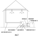
- the leak detection sensor is disposed in a location of the fan coil unit (FCU) where refrigerant leaking from the system can pool due to a higher density than air as illustrated in FIG. 2 .
- FCU fan coil unit
- the air conditioning system 10 includes an outdoor unit 12 that is disposed at an exterior of the building 11, an indoor unit 13 that includes an evaporator and is disposed in an interior of the building 11 and an enclosure 14.
- the outdoor unit 12 includes a fan and a condenser, which is fluidly coupled to the evaporator of the indoor unit 13 by way of input piping 15 and return piping 16.
- the condenser, the evaporator (i.e., fan coil unit), the input piping 15 and the return piping 16 cooperatively form a refrigerant circuit for, in this case, moderate-to-low GWP value refrigerant (e.g., R32).
- the fan of the outdoor unit 12 blows air over the condenser to remove heat from the refrigerant to eject heat and cause refrigerant vapor to condense to liquid.
- the cooled liquid refrigerant is then pumped through the input piping 15 toward the indoor unit 13 by pump 17, which is operably disposed on the input piping 15, whereupon the cooled refrigerant in the FCU evaporates, cooling the air passing through the FCU. Cool air is then circulated into occupied space for human comfort.
- Multiple FCUs can be installed in individual rooms to space temperature conditioning. Refrigerant can potentially leak into the occupied space through the FCUs or pipes. Likewise, refrigerant can leak into air duct and accumulate in an area that can potential contain an ignition source. These rare events could lead to undesirable consequences such as fire hazard and causing damages to properties.
- the enclosure 14 includes a main section 140 that surrounds the indoor unit 13 and has an outlet 141 and a return air duct 142, an optional vent 143 that is opened and closed by a damper 144 and a conditioned air duct 145.
- conditioned air is supplied to the occupied space through conditioned air duct 145.
- Return air is circulated partially or fully through the return air duct 142 to sustain desired operation.
- LFL low flammable limit
- Damper 144 is engaged based on the leak detection device response and resulting hazardous conditions for minimize the risk. Specifically, if dilution within the building is deemed insufficient for mitigating the flammability risk or combustion of refrigerant has occurred, venting to the outside is the best option.
- the air conditioning system 10 further includes a fan 17, a refrigerant detection sensor 30 and a controller 40.
- the fan 17 may be provided as a fan-coil unit of the evaporator and is disposed and configured for supplying air to the occupied space of the building 11.
- the refrigerant detection sensor 30 is disposed in the enclosure 14 and, in some cases, along the sample duct 147 and is configured for operation in first and second modes. In the first mode, the refrigerant detection sensor 30 intermittently executes a calibration or recalibration process by which the refrigerant detection sensor 30 establishes a baseline response for itself to tests run on sample drawn from the sample duct 147.
- the refrigerant detection sensor 30 executes leak detection operations with respect to a presence of refrigerant in samples drawn from the sample duct 147.
- the leak detection operations are thus based on comparisons between responses of the refrigerant detection sensor 30 and the baseline response in accordance with a most recent recalibration.
- the refrigerant detection sensor 30 is further configured for providing a binary output of leak and non-leak signals.
- the controller 40 of the air conditioner is configured to control operations of the fan 17, the vent 143 and the damper 144 based on the binary output of the refrigerant detection sensor 30 that is physically wired to the controller or communicates with the controller via wired or wireless communication .
- the refrigerant detection sensor 30 includes an optical detection assembly 31 and supporting electronics and associated firmware 32.
- the detection assembly 31 includes an emitter 310, a detector 311, an optical element 312 and a band pass filter 313.
- the emitter 310 may be provided as a broad wavelength emitter of electro-magnetic radiation or as a narrow band emitter of electro-magnetic radiation at specific wavelengths (e.g., 2.8 to 3.2 microns for refrigerant R32, difluoromethane).
- the electro-magnetic radiation may be IR radiation and, for purposes of clarity and brevity, the following description will relate to this exemplary case.
- the detector 311 may be provided as an IR detector, such as a thermopile or another similar device.
- the optical element 312 may be provided as a mirror or specular surface and is disposed and configured to reflect the IR radiation emitted by the emitter 310 toward the detector 311 such that the IR radiation passes through an elongate section 314 of the enclosure 14.
- the band pass filter 313 is disposed along an IR radiation pathway between the emitter 310 and the detector 311 and serves to filter out IR radiation signals that are not associated with the response of the moderate-to-low GWP value refrigerant to the IR radiation emitted by the emitter 310 while allowing IR radiation signals that are associated with the response of the moderate-to-low GWP value refrigerant to the IR radiation emitted by the emitter 310 to propagate to the detector 311.
- the band pass filter 313 may be provided as a glass window and may be disposed proximate to the emitter 310 (i.e., upstream from the optical element 312) or proximate to the detector 311 (i.e., downstream from the optical element 312).
- the radiation pathway provided by the optical element 312 is substantially longer than it otherwise could be given the width of the enclosure 14. That is, since the radiation pathway has a forward component from the emitter 310 to the optical element 312 and a reverse component from the optical element 312 to the detector 311, the radiation pathway is actually twice as long as it would be without the optical element 312. This additional length provides for additional exposure of the moderate-to-low GWP value refrigerant to the IR radiation emitted by the emitter 310 and thus a greater and more reliable response of the detector 311.
- the detection assembly 31 may be configured to detect one type of the moderate-to-low GWP value refrigerant as shown in FIG. 3 or multiple types of the moderate-to-low GWP value refrigerant.
- a beam splitter 315 could be disposed along the IR radiation pathway to split the IR radiation into at least first and second beam components directed through corresponding first and second band pass filters 313 and toward corresponding first and second detectors 311.
- the first and second band pass filters 313 may be configured to allow IR radiation of different wavelengths to pass through to the first and second detectors 311 so that IR radiation signals that are associated with the response of multiple moderate-to-low GWP value refrigerants to the IR radiation emitted by the emitter 310 are allowed to propagate to the first and second detectors 311.
- a switching element 316 could be disposed to manually or automatically switch one band pass filter 313 for another so that a type of a moderate-to-low GWP value refrigerant being detected could be correspondingly switched to another type.
- the detector (or detectors) 311 receives IR radiation signals whose spectra are reflective of either a refrigerant leak condition or a refrigerant non-leak condition. In both cases, the detector 311 issues signals corresponding to the refrigerant leak or non-leak conditions to the supporting electronics and associated firmware 32.
- the supporting electronics and associated firmware 32 is receptive of these signals and is configured for generation of the binary output based thereon and for issuance of the binary output to the controller 40 by way of relay 45.
- the supporting electronics and associated firmware 32 may include an analog-to-binary output conversion circuit or, more particularly, a step function circuit, a monostable circuit, a 1-shot circuit or another similar type of circuit. A particular design of the supporting electronics and associated firmware 32 is illustrated in FIG. 10 .
- the detector (or detectors) 311 receives an IR radiation signal whose spectrum is reflective of a refrigerant leak condition
- the detector 311 issues signals corresponding to the refrigerant leak condition to the supporting electronics and associated firmware 32 and the supporting electronics and associated firmware 32 generates a binary output "1" for issuance to the controller 40 so that mitigation efforts can be activated.
- the detector (or detectors) 311 receives an IR radiation signal whose spectrum is reflective of a refrigerant non-leak condition
- the detector 311 issues signals corresponding to the refrigerant non-leak condition to the supporting electronics and associated firmware 32 and the supporting electronics and associated firmware 32 generates a binary output "0" for issuance to the controller 40 so that mitigation efforts can be deactivated or maintained in a deactivated state.
- the detection assembly 31 and the supporting electronics and associated firmware 32 need not include complex optical or electronic components that evaluate a concentration of the leaked or non-leaked refrigerant in the enclosure 14.
- the refrigerant detection sensor 30 may be disposed in or close to a pooling region 50 of the enclosure 14.
- This pooling region 50 may be defined at or close to a lowest region in an interior of the enclosure 14 (see FIG. 7 ) or to an elevated section 51 of the interior of the enclosure 14 where liquids and/or vapor tend to accumulate and pool together (see FIG. 8 ).
- the refrigerant detection sensor 30 may be configured to operate on its own or the controller 40 may be configured to operate the refrigerant detection sensor 30.
- the intermittent baseline calibration of the refrigerant detection sensor 30 includes an establishment of a baseline response of the refrigerant detection sensor 30 to an execution of leak detection at certain times (e.g., when components of the air conditioning system 10 are activated, when the indoor unit 13 is activated, when the fan 20 is activated) and/or at predefined intervals.
- the self-calibration of sensor 30 may be conducted at the wavelength utilized for refrigerant leak detection or at a different wavelength enabled by a second band-path filter, for instance the wavelength at which carbon dioxide has detectable absorption.
- the intermittent baseline calibration of the refrigerant detection sensor 30 allows the detection assembly 31 and the supporting electronics and associated firmware 32 to continue to operate reliably.
- the refrigerant detection sensor 30 may execute (on its own or in response to commands issued by the controller 40) diagnostics at the certain times and/or the predefined intervals.
- a method of operating the above-described air conditioning system 10 includes intermittently recalibrating the refrigerant detection sensor 30 at the certain times and/or the predefined intervals, setting the refrigerant detection sensor to a detection mode and iteratively determining, at the refrigerant detection sensor 30, that a concentration of the refrigerant in a sample drawn from the enclosure 14 exceeds a threshold defined in accordance with the most recent recalibration of the refrigerant detection sensor 30.
- the method further includes setting a binary output of the refrigerant detection sensor to correspond to a leak signal in an event the concentration exceeds the threshold or a non-leak signal in an event the concentration does not exceed the threshold and either mitigating the leakage of the refrigerant based on the binary output corresponding to the leak signal or halting the mitigation.
- the mitigating of the leakage of the refrigerant includes an activation of the fan 17 and an opening of the vent 143 by the damper 144, which can be optional for some systems.
- fluid e.g., air
- the mitigation efforts reduce the risk of fire due to the refrigerant, which in this case is mildly flammable, remaining in the building 11.
- the halting of the mitigation includes a deactivation of the fan 17 and a closing of the vent 143 by the damper 144.
- a variant of this embodiment can achieve the same mitigation results without having a damper by circulating air within a house or building to dilute the refrigerant that accumulates in the duct or any confined space. This is applicable when the concentration of refrigerant when fully dispersed in the build will lead to non-flammable situation, i.e. less than the lower flammable limit (LFL) or even more strictly less than 25% LFL.
- LFL lower flammable limit
- an output V IRB of the detector 311 is stored (block 901) having been updated based on a predetermined threshold change rate such as -2mV/month (block 902).
- a present reading of the output V IRO of the detector 311 is taken (block 903) and it is determined whether a difference between the two outputs exceed a threshold output change of a detector 311 for activating the fan 17 in the event of a refrigerant leak ⁇ V T (block 904).
- a signal is sent to the relay 45 and then to the system controller 40 such that the fan 17 is turned on for a given extended period of time (block 906) and then turned off (block 907). If the difference does not exceed the threshold output change ⁇ V T but still exceeds a nuisance alarm threshold ⁇ V N (block 909), a nuisance alarm is registered by controller 40 (block 910) and it is again determined whether the output V IRB has been updated recently (block 911.). If not, the fan 17 is turned on for the abbreviated given period of time (block 908) and then turned off (block 907). If so, the output V IRB of the detector 311 is stored (block 901).
- the controller 40 includes a firmware 401 embedded in the PIC component 403, an analog to digit converter 402 and a system controller.
- Other sensor control logic includes an emitter duty cycle timer that is coupled to the refrigerant detection sensor 30, an amplifier that is configured to amplify signals issued by the refrigerant detection system 30 and an A/D converter.
- the firmware 401 processes signals from the A/D converter and regulates a measurement timer , a measurement value (i.e. sample measurement), a reference measurement value and a reference timer.
- the sample measurement value and the reference measurement value are compared in hazard comparator 404 and an output of the hazard comparator 404, the reference timer value and a control program 403 of the PIC component are computed and compared as referenced in FIG. 9 , where two thresholds ⁇ V T and/or ⁇ V N are examined for actions or the system fan or the miniature fan associated with the sensor is turned on for the abbreviated given period of time (block 908) for updating V IRB .
- the reference timer is utilized to regulate whether the re-baselining is due while considering the most recent record of V IRB update triggered by either a leak event or simply the baseline update action.
- the overall logic can also include temperature compensation of the detector response based on an input from a temperature sensor disposed with the sensing device or attached to the FCU.
- An output of the OR gate unit 405 is then fed back into the system control component 403 as a feedback control feature.
- the AC system controller provides the status of the system so that leak detection device PIC can determine if the logic aforementioned would be implemented or partially implemented. This is so because when the system is operating in a cooling mode, the system fan is supposed to operate such that the leak detection device remain in a standby status except the baseline update logic (block 911) is engaged if the reference timer determines the last update occurred more than a pre-determined interval (i.e., 1 month).
- the air conditioning system 10 and the refrigerant detection sensor 30 in particular will enable minimum but sufficient device configuration and functions, drift and degradation issues inherent to NDIR sensors overcome without sacrificing sufficient safety margins in the event of hazardous leaks occurring and an elimination of the need for sensor calibration.
Landscapes
- Engineering & Computer Science (AREA)
- Chemical & Material Sciences (AREA)
- Physics & Mathematics (AREA)
- Combustion & Propulsion (AREA)
- Mechanical Engineering (AREA)
- General Engineering & Computer Science (AREA)
- Spectroscopy & Molecular Physics (AREA)
- Fluid Mechanics (AREA)
- Life Sciences & Earth Sciences (AREA)
- Analytical Chemistry (AREA)
- Biochemistry (AREA)
- General Health & Medical Sciences (AREA)
- General Physics & Mathematics (AREA)
- Immunology (AREA)
- Pathology (AREA)
- Health & Medical Sciences (AREA)
- Air Conditioning Control Device (AREA)
Abstract
Description
- The following description relates to moderate-to-low global warming potential (GWP) value refrigerant leak detection and, more particularly, to a controllable moderate-to-low GWP value refrigerant leak detector and a method of operating the same.
- Air conditioning systems for residential or commercial buildings typically include an outdoor unit and an indoor unit. The outdoor unit drives airflow into the indoor unit where that airflow is cooled by thermal interaction with a refrigerant. This refrigerant, historically, has been provided as a fluid with a high global warming potential (GWP) value such as R134A or R410A. Thus, although the refrigerants that have been used previously are effective coolants, the negative effect they can have on the environment has led to the institution of requirements that new refrigerants which have moderate-to-low GWP values be employed instead.
- Moderate-to-low GWP value refrigerants (i.e., A2L) can be mildly flammable, however, and thus their use in air conditioning systems can present a fire risk that needs to be addressed. In particular, to the extent that refrigerant leaks are possible in air conditioning systems, the use of moderate-to-low GWP value refrigerants makes the use of refrigerant leak detectors mandatory especially for indoor units of ducted residential heating, ventilation and air conditioning (HVAC) products and other similar systems. To this end, while commercial non-dispersive infrared (NDIR) sensors are available, they can be unacceptably expensive due to their optical and electronic components accounting for approximately 40-60% of the costs and generally being over-designed for leak detection applications.
- That is, while the optical and electronic components of NDIR sensors are usually designed to accurately determine gas concentrations for demand based ventilation, greenhouse applications, etc., leak detection sensing requires only that the presence of refrigerant arising from leakage be detected and does not need an accurate determination of a concentration of such refrigerant.
- According to one aspect of the disclosure, an air conditioning system is provided and includes a unit receptive of refrigerant having a moderate-to-low global warming potential (GWP) value for thermal interaction with a fluid, an enclosure, a fan disposed and configured for urging a flow of the fluid through the unit, a refrigerant detection sensor and a controller. The refrigerant detection sensor is disposed in the enclosure to be operable in a first mode in which a baseline response is established and a second mode in which refrigerant leak detection is executed based on the baseline response. The refrigerant detection sensor is further configured to generate a binary output of leak and non-leak signals in accordance with a result of the refrigerant leak detection. The controller is configured to control operations of the fan and the vent based on the binary output.
- In accordance with additional or alternative embodiments, the refrigerant detection sensor is disposed proximate to a pooling region of the enclosure.
- In accordance with additional or alternative embodiments, the refrigerant detection sensor includes a detection assembly and an actuation assembly receptive of a signal from the detection assembly and configured for generation of the binary output based on the signal and for issuance of the binary output to the controller.
- In accordance with additional or alternative embodiments, the detection assembly includes an emitter, a detector, an optical element to reflect radiation emitted by the emitter toward the detector such that the radiation passes through an elongate section of the enclosure and a band pass filter disposed along a radiation pathway between the emitter and the detector.
- In accordance with additional or alternative embodiments, the detection assembly is configured to detect multiple types of the refrigerant.
- In accordance with additional or alternative embodiments, the detection assembly further includes a flow driving element.
- In accordance with additional or alternative embodiments, the actuation assembly includes an analog-to-binary output conversion circuit.
- In accordance with additional or alternative embodiments, the intermittent baseline calibration includes establishing a baseline response of the refrigerant detection sensor to an execution of leak detection.
- In accordance with additional or alternative embodiments, the refrigerant detection sensor recalibrates at certain times and/or at predefined intervals.
- In accordance with additional or alternative embodiments, the refrigerant detection sensor executes diagnostics at the certain times and/or the predefined intervals.
- In accordance with additional or alternative embodiments, the leak detection includes an iterative determination that a concentration of the refrigerant in a sample drawn from the enclosure exceeds first or second thresholds defined in accordance with the most recent recalibration, a setting of the binary output to correspond to the leak signal in an event the concentration exceeds either of the first or second thresholds and a setting of the binary output to correspond to the non-leak signal in an event the concentration does not exceed either of the first or second thresholds.
- In accordance with additional or alternative embodiments, the controller activates the fan for extended or abbreviated periods of time and opens the vent based on the binary output corresponding to the leak signal and in the event the concentration exceeds either of the first or second thresholds, respectively, and deactivates the fan and closes the vent based on the binary output corresponding to the non-leak signal.
- In accordance with additional or alternative embodiments, the controller includes a relay electrically interposed between the refrigerant detection sensor and the fan and the vent.
- According to another aspect of the disclosure, a controllable moderate-to-low global warming potential (GWP) value refrigerant leak detector is provided. The controllable moderate-to-low GWP value refrigerant leak detector includes a detection assembly. The detection assembly includes an emitter, a detector, an optical element to reflect radiation emitted by the emitter toward the detector such that the radiation passes through an elongate section of an enclosure and a band pass filter disposed along a radiation pathway between the emitter and the detector. The band pass filter is tuned for detection of the moderate-to-low GWP value refrigerant. The detector is receptive of a portion of the radiation passing through the band pass filter. The controllable moderate-to-low GWP value refrigerant leak detector further includes an actuation assembly receptive of a signal, which is reflective of a magnitude of the portion of the radiation, from the detector and configured for generation of a binary output based on the signal and for issuance of the binary output to a fan/vent controller.
- According to yet another aspect of the disclosure, a method of operating an air conditioning system that includes a refrigerant detection sensor configured to execute leak detection with respect to leakage of refrigerant having a moderate-to-low global warming potential (GWP) value into an enclosure is provided. The method includes recalibrating the refrigerant detection sensor, setting the refrigerant detection sensor to a detection mode, iteratively determining, at the refrigerant detection sensor, that a concentration of the refrigerant in a sample drawn from the enclosure exceeds a threshold defined in accordance with a most recent recalibration, setting a binary output of the refrigerant detection sensor to correspond to leak or non-leak signals in an event the concentration exceeds or does not exceed the threshold, respectively, and mitigating the leakage of the refrigerant based on the binary output corresponding to the leak signal.
- In accordance with additional or alternative embodiments, the refrigerant detection sensor includes a detection assembly and an actuation assembly receptive of a signal from the detection assembly and configured for generation of the binary output based on the signal and for issuance of the binary output to the controller.
- In accordance with additional or alternative embodiments, the detection assembly includes an emitter, a detector, an optical element to reflect radiation emitted by the emitter toward the detector such that the radiation passes through an elongate section of the enclosure and a band pass filter disposed along a radiation pathway between the emitter and the detector.
- In accordance with additional or alternative embodiments, the detection assembly is configured to detect multiple types of the refrigerant.
- In accordance with additional or alternative embodiments, the method further includes executing diagnostics at the predefined intervals.
- In accordance with additional or alternative embodiments, the mitigating includes activating a fan and opening a vent based on the binary output corresponding to the leak signal and deactivating the fan and closing the vent based on the binary output corresponding to the non-leak signal.
- These and other advantages and features will become more apparent from the following description taken in conjunction with the drawings.
- The subject matter, which is regarded as the disclosure, is particularly pointed out and distinctly claimed in the claims at the conclusion of the specification. The foregoing and other features, and advantages of the disclosure are apparent from the following detailed description taken in conjunction with the accompanying drawings in which:
-
FIG. 1 is a schematic illustration of an air conditioning system in accordance with embodiments; -
FIG. 2 is a schematic illustration of an air conditioning system in accordance with alternative embodiments; -
FIG. 3 is a schematic illustration of a controllable moderate-to-low global warming potential (GWP) value refrigerant leak detector for use with the air conditioning system ofFIG. 1 (orFIG. 2 ) in accordance with embodiments; -
FIG. 4 is a perspective view of a refrigerant detection sensor with its own mini-fan attached in accordance with embodiments; -
FIG. 5 is a schematic illustration of a controllable moderate-to-low global warming potential (GWP) value refrigerant leak detector for use with the air conditioning system ofFIG. 1 in accordance with further embodiments; -
FIG. 6 is a schematic illustration of a controllable moderate-to-low global warming potential (GWP) value refrigerant leak detector for use with the air conditioning system ofFIG. 1 (orFIG. 2 ) in accordance with further embodiments; -
FIG. 7 is a side view of an enclosure of an indoor unit of the air conditioning system ofFIG. 1 (orFIG. 2 ) in accordance with embodiments; -
FIG. 8 is a side view of an enclosure of an indoor unit of the air conditioning system ofFIG. 1 (orFIG. 2 ) in accordance with alternative embodiments; -
FIG. 9 is a flow diagram illustrating a method of operating an optical sensor of the controllable moderate-to-low global warming potential (GWP) value refrigerant leak detector ofFIG. 3 ; and -
FIG. 10 is a schematic diagram of components and constituent logic embedded in the leak detection device in the form of firmware coded in its own programmed integrated circuit (PIC) independent of a controller of the air conditioning system ofFIG. 1 (orFIG. 2 ) in accordance with further embodiments. - As will be described below, a refrigerant detection sensor is provided. The refrigerant detection sensor produces discrete, such as binary signals that are indicative of refrigerant leak and non-leak conditions, including warning conditions by tracking a differential intensity of radiation (e.g., infrared (IR) radiation) that is received by a detector relative to a known baseline state. The refrigerant detection sensor includes a source or emitter, a band pass filter, a detector and a circuit (e.g., a step function circuit, a monostable circuit, 1-shot circuit or another similar type of circuit) that operates by converting a continuous analog output to discrete output, including a binary output. The band pass filter can be tuned to target key refrigerants while the emitter can be a broad bandwidth IR source or an integrated broad bandwidth source. A main controller of the air conditioning unit comprising a relay receives output from the circuit for activating a fan or blower to circulate air for ventilating and diluting leaked refrigerant. Moreover, a baseline reading of the detector can be refreshed so that the sensor can operate without calibration even though the emitter degrades over time.
- With reference to
FIGS. 1 ,2 and3 , anair conditioning system 10 is provided for use with abuilding 11, such as a residence or commercial building, and may be configured as a ductless or ducted system. For purposes of clarity and brevity, however, the following description will relate to the exemplary case of theair conditioning system 10 being a ducted system. More specifically, the leak detection sensor is disposed in a location of the fan coil unit (FCU) where refrigerant leaking from the system can pool due to a higher density than air as illustrated inFIG. 2 . - Thus, as shown in
FIGS. 1 ,2 and3 , theair conditioning system 10 includes anoutdoor unit 12 that is disposed at an exterior of thebuilding 11, anindoor unit 13 that includes an evaporator and is disposed in an interior of thebuilding 11 and anenclosure 14. Theoutdoor unit 12 includes a fan and a condenser, which is fluidly coupled to the evaporator of theindoor unit 13 by way of input piping 15 and returnpiping 16. The condenser, the evaporator (i.e., fan coil unit), the input piping 15 and the return piping 16 cooperatively form a refrigerant circuit for, in this case, moderate-to-low GWP value refrigerant (e.g., R32). - During operations of the refrigerant circuit, the fan of the
outdoor unit 12 blows air over the condenser to remove heat from the refrigerant to eject heat and cause refrigerant vapor to condense to liquid. The cooled liquid refrigerant is then pumped through the input piping 15 toward theindoor unit 13 bypump 17, which is operably disposed on the input piping 15, whereupon the cooled refrigerant in the FCU evaporates, cooling the air passing through the FCU. Cool air is then circulated into occupied space for human comfort. Multiple FCUs can be installed in individual rooms to space temperature conditioning. Refrigerant can potentially leak into the occupied space through the FCUs or pipes. Likewise, refrigerant can leak into air duct and accumulate in an area that can potential contain an ignition source. These rare events could lead to undesirable consequences such as fire hazard and causing damages to properties. - The
enclosure 14 includes amain section 140 that surrounds theindoor unit 13 and has anoutlet 141 and areturn air duct 142, anoptional vent 143 that is opened and closed by adamper 144 and aconditioned air duct 145. During normal cooling operation, conditioned air is supplied to the occupied space through conditionedair duct 145. Return air is circulated partially or fully through thereturn air duct 142 to sustain desired operation. Under rare events of refrigerant leak substantial to cause hazardous conditions, such as those exceeding 25% low flammable limit (LFL), air circulation is activated to dilute the refrigerant in the building or air is directed to exist the building viadamper 144 to the outdoor environment.Damper 144 is engaged based on the leak detection device response and resulting hazardous conditions for minimize the risk. Specifically, if dilution within the building is deemed insufficient for mitigating the flammability risk or combustion of refrigerant has occurred, venting to the outside is the best option. - With continued reference to
FIGS. 1 ,2 and3 , theair conditioning system 10 further includes afan 17, arefrigerant detection sensor 30 and acontroller 40. Thefan 17 may be provided as a fan-coil unit of the evaporator and is disposed and configured for supplying air to the occupied space of thebuilding 11. Therefrigerant detection sensor 30 is disposed in theenclosure 14 and, in some cases, along thesample duct 147 and is configured for operation in first and second modes. In the first mode, therefrigerant detection sensor 30 intermittently executes a calibration or recalibration process by which therefrigerant detection sensor 30 establishes a baseline response for itself to tests run on sample drawn from thesample duct 147. In the second mode, therefrigerant detection sensor 30 executes leak detection operations with respect to a presence of refrigerant in samples drawn from thesample duct 147. The leak detection operations are thus based on comparisons between responses of therefrigerant detection sensor 30 and the baseline response in accordance with a most recent recalibration. When operating in the second mode, therefrigerant detection sensor 30 is further configured for providing a binary output of leak and non-leak signals. Thecontroller 40 of the air conditioner is configured to control operations of thefan 17, thevent 143 and thedamper 144 based on the binary output of therefrigerant detection sensor 30 that is physically wired to the controller or communicates with the controller via wired or wireless communication . The structural details of at least therefrigerant detection sensor 30 and thecontroller 40 and their various respective functions and operations will be described in greater detail below. - As shown in
FIG. 3 , therefrigerant detection sensor 30 includes anoptical detection assembly 31 and supporting electronics and associatedfirmware 32. - The
detection assembly 31 includes anemitter 310, adetector 311, anoptical element 312 and aband pass filter 313. Theemitter 310 may be provided as a broad wavelength emitter of electro-magnetic radiation or as a narrow band emitter of electro-magnetic radiation at specific wavelengths (e.g., 2.8 to 3.2 microns for refrigerant R32, difluoromethane). In either case, the electro-magnetic radiation may be IR radiation and, for purposes of clarity and brevity, the following description will relate to this exemplary case. Thedetector 311 may be provided as an IR detector, such as a thermopile or another similar device. Theoptical element 312 may be provided as a mirror or specular surface and is disposed and configured to reflect the IR radiation emitted by theemitter 310 toward thedetector 311 such that the IR radiation passes through anelongate section 314 of theenclosure 14. Theband pass filter 313 is disposed along an IR radiation pathway between theemitter 310 and thedetector 311 and serves to filter out IR radiation signals that are not associated with the response of the moderate-to-low GWP value refrigerant to the IR radiation emitted by theemitter 310 while allowing IR radiation signals that are associated with the response of the moderate-to-low GWP value refrigerant to the IR radiation emitted by theemitter 310 to propagate to thedetector 311. Theband pass filter 313 may be provided as a glass window and may be disposed proximate to the emitter 310 (i.e., upstream from the optical element 312) or proximate to the detector 311 (i.e., downstream from the optical element 312). - With the construction described above and illustrated in
FIG. 3 , the radiation pathway provided by theoptical element 312 is substantially longer than it otherwise could be given the width of theenclosure 14. That is, since the radiation pathway has a forward component from theemitter 310 to theoptical element 312 and a reverse component from theoptical element 312 to thedetector 311, the radiation pathway is actually twice as long as it would be without theoptical element 312. This additional length provides for additional exposure of the moderate-to-low GWP value refrigerant to the IR radiation emitted by theemitter 310 and thus a greater and more reliable response of thedetector 311. - With reference to
FIG. 4 , thedetection assembly 31 may further include aflow driving element 33. Theflow driving element 33 may include a fan element, as shown inFIG. 4 , a heating element or another similar device. In any case, theflow driving element 33 draws air through thedetection assembly 31 and can serve to dilute impurities or refrigerants for establishing baseline responses and to improve historical tracking for calibration. - With reference to
FIGS. 5 and 6 , thedetection assembly 31 may be configured to detect one type of the moderate-to-low GWP value refrigerant as shown inFIG. 3 or multiple types of the moderate-to-low GWP value refrigerant. For example, as shown inFIG. 5 , abeam splitter 315 could be disposed along the IR radiation pathway to split the IR radiation into at least first and second beam components directed through corresponding first and second band pass filters 313 and toward corresponding first andsecond detectors 311. Here, the first and second band pass filters 313 may be configured to allow IR radiation of different wavelengths to pass through to the first andsecond detectors 311 so that IR radiation signals that are associated with the response of multiple moderate-to-low GWP value refrigerants to the IR radiation emitted by theemitter 310 are allowed to propagate to the first andsecond detectors 311. Meanwhile, as shown inFIG. 6 , aswitching element 316 could be disposed to manually or automatically switch oneband pass filter 313 for another so that a type of a moderate-to-low GWP value refrigerant being detected could be correspondingly switched to another type. - With reference back to
FIG. 3 , the detector (or detectors) 311 receives IR radiation signals whose spectra are reflective of either a refrigerant leak condition or a refrigerant non-leak condition. In both cases, thedetector 311 issues signals corresponding to the refrigerant leak or non-leak conditions to the supporting electronics and associatedfirmware 32. The supporting electronics and associatedfirmware 32 is receptive of these signals and is configured for generation of the binary output based thereon and for issuance of the binary output to thecontroller 40 by way ofrelay 45. The supporting electronics and associatedfirmware 32 may include an analog-to-binary output conversion circuit or, more particularly, a step function circuit, a monostable circuit, a 1-shot circuit or another similar type of circuit. A particular design of the supporting electronics and associatedfirmware 32 is illustrated inFIG. 10 . - In accordance with embodiments, in an event the detector (or detectors) 311 receives an IR radiation signal whose spectrum is reflective of a refrigerant leak condition, the
detector 311 issues signals corresponding to the refrigerant leak condition to the supporting electronics and associatedfirmware 32 and the supporting electronics and associatedfirmware 32 generates a binary output "1" for issuance to thecontroller 40 so that mitigation efforts can be activated. Conversely, in an event the detector (or detectors) 311 receives an IR radiation signal whose spectrum is reflective of a refrigerant non-leak condition, thedetector 311 issues signals corresponding to the refrigerant non-leak condition to the supporting electronics and associatedfirmware 32 and the supporting electronics and associatedfirmware 32 generates a binary output "0" for issuance to thecontroller 40 so that mitigation efforts can be deactivated or maintained in a deactivated state. As such, since the binary output is all that is needed to be issued to thecontroller 40, thedetection assembly 31 and the supporting electronics and associatedfirmware 32 need not include complex optical or electronic components that evaluate a concentration of the leaked or non-leaked refrigerant in theenclosure 14. - With reference to
FIGS. 7 and 8 , therefrigerant detection sensor 30 may be disposed in or close to a poolingregion 50 of theenclosure 14. This poolingregion 50 may be defined at or close to a lowest region in an interior of the enclosure 14 (seeFIG. 7 ) or to anelevated section 51 of the interior of theenclosure 14 where liquids and/or vapor tend to accumulate and pool together (seeFIG. 8 ). - The
refrigerant detection sensor 30 may be configured to operate on its own or thecontroller 40 may be configured to operate therefrigerant detection sensor 30. In either case, the intermittent baseline calibration of therefrigerant detection sensor 30 includes an establishment of a baseline response of therefrigerant detection sensor 30 to an execution of leak detection at certain times (e.g., when components of theair conditioning system 10 are activated, when theindoor unit 13 is activated, when the fan 20 is activated) and/or at predefined intervals. The self-calibration ofsensor 30 may be conducted at the wavelength utilized for refrigerant leak detection or at a different wavelength enabled by a second band-path filter, for instance the wavelength at which carbon dioxide has detectable absorption. In any case, since it is expected that therefrigerant detection sensor 30 might degrade over time, the intermittent baseline calibration of therefrigerant detection sensor 30 allows thedetection assembly 31 and the supporting electronics and associatedfirmware 32 to continue to operate reliably. In accordance with further embodiments, however, therefrigerant detection sensor 30 may execute (on its own or in response to commands issued by the controller 40) diagnostics at the certain times and/or the predefined intervals. - A method of operating the above-described
air conditioning system 10 is also provided. The method includes intermittently recalibrating therefrigerant detection sensor 30 at the certain times and/or the predefined intervals, setting the refrigerant detection sensor to a detection mode and iteratively determining, at therefrigerant detection sensor 30, that a concentration of the refrigerant in a sample drawn from theenclosure 14 exceeds a threshold defined in accordance with the most recent recalibration of therefrigerant detection sensor 30. The method further includes setting a binary output of the refrigerant detection sensor to correspond to a leak signal in an event the concentration exceeds the threshold or a non-leak signal in an event the concentration does not exceed the threshold and either mitigating the leakage of the refrigerant based on the binary output corresponding to the leak signal or halting the mitigation. - In accordance with embodiments, the mitigating of the leakage of the refrigerant includes an activation of the
fan 17 and an opening of thevent 143 by thedamper 144, which can be optional for some systems. Here, fluid (e.g., air) that is blown by thefan 17 mixes with the leaked refrigerant and drives the leaked refrigerant out of thebuilding 11 via thevent 143. In so doing, the mitigation efforts reduce the risk of fire due to the refrigerant, which in this case is mildly flammable, remaining in thebuilding 11. Conversely, the halting of the mitigation includes a deactivation of thefan 17 and a closing of thevent 143 by thedamper 144. A variant of this embodiment can achieve the same mitigation results without having a damper by circulating air within a house or building to dilute the refrigerant that accumulates in the duct or any confined space. This is applicable when the concentration of refrigerant when fully dispersed in the build will lead to non-flammable situation, i.e. less than the lower flammable limit (LFL) or even more strictly less than 25% LFL. - With reference to
FIG. 9 , a further method of operating the above-describedair conditioning system 10 is provided. As shown inFIG. 9 , in an initial operation, an output VIRB of thedetector 311 is stored (block 901) having been updated based on a predetermined threshold change rate such as -2mV/month (block 902). Subsequently, a present reading of the output VIRO of thedetector 311 is taken (block 903) and it is determined whether a difference between the two outputs exceed a threshold output change of adetector 311 for activating thefan 17 in the event of a refrigerant leak ΔVT (block 904). If this difference exceeds the threshold output change ΔVT, a signal is sent to therelay 45 and then to thesystem controller 40 such that thefan 17 is turned on for a given extended period of time (block 906) and then turned off (block 907). If the difference does not exceed the threshold output change ΔVT but still exceeds a nuisance alarm threshold ΔVN (block 909), a nuisance alarm is registered by controller 40 (block 910) and it is again determined whether the output VIRB has been updated recently (block 911.). If not, thefan 17 is turned on for the abbreviated given period of time (block 908) and then turned off (block 907). If so, the output VIRB of thedetector 311 is stored (block 901). - With reference to
FIG. 10 , thecontroller 40 includes afirmware 401 embedded in thePIC component 403, an analog todigit converter 402 and a system controller. Other sensor control logic includes an emitter duty cycle timer that is coupled to therefrigerant detection sensor 30, an amplifier that is configured to amplify signals issued by therefrigerant detection system 30 and an A/D converter. Thefirmware 401 processes signals from the A/D converter and regulates a measurement timer , a measurement value (i.e. sample measurement), a reference measurement value and a reference timer. The sample measurement value and the reference measurement value are compared inhazard comparator 404 and an output of thehazard comparator 404, the reference timer value and acontrol program 403 of the PIC component are computed and compared as referenced inFIG. 9 , where two thresholds ΔVT and/or ΔVN are examined for actions or the system fan or the miniature fan associated with the sensor is turned on for the abbreviated given period of time (block 908) for updating VIRB. The reference timer is utilized to regulate whether the re-baselining is due while considering the most recent record of VIRB update triggered by either a leak event or simply the baseline update action. The overall logic can also include temperature compensation of the detector response based on an input from a temperature sensor disposed with the sensing device or attached to the FCU. An output of theOR gate unit 405 is then fed back into thesystem control component 403 as a feedback control feature. The AC system controller provides the status of the system so that leak detection device PIC can determine if the logic aforementioned would be implemented or partially implemented. This is so because when the system is operating in a cooling mode, the system fan is supposed to operate such that the leak detection device remain in a standby status except the baseline update logic (block 911) is engaged if the reference timer determines the last update occurred more than a pre-determined interval (i.e., 1 month). - With the configurations described herein, the
air conditioning system 10 and therefrigerant detection sensor 30 in particular will enable minimum but sufficient device configuration and functions, drift and degradation issues inherent to NDIR sensors overcome without sacrificing sufficient safety margins in the event of hazardous leaks occurring and an elimination of the need for sensor calibration. - While the disclosure is provided in detail in connection with only a limited number of embodiments, it should be readily understood that the disclosure is not limited to such disclosed embodiments. Rather, the disclosure can be modified to incorporate any number of variations, alterations, substitutions or equivalent arrangements not heretofore described, but which are commensurate with the spirit and scope of the disclosure. Additionally, while various embodiments of the disclosure have been described, it is to be understood that the exemplary embodiment(s) may include only some of the described exemplary aspects. Accordingly, the disclosure is not to be seen as limited by the foregoing description, but is only limited by the scope of the appended claims.
- The following clauses set out features of the invention which may or many not be presently claimed in this application, but which may form the basis for future amendment or a divisional application.
- 1. An air conditioning system, comprising:
- a unit receptive of a refrigerant having a moderate-to-low global warming potential (GWP) value for thermal interaction with a fluid;
- an enclosure comprising a main section surrounding the unit and having a vent, an outlet and an inlet, an exhaust duct leading from the outlet to the vent and a return-air duct extending from the exhaust duct to the inlet;
- a fan disposed and configured for urging a flow of the fluid through the unit;
- a refrigerant detection sensor disposed in the enclosure to be operable in a first mode in which a baseline response is established and a second mode in which refrigerant leak detection is executed based on the baseline response; the refrigerant detection sensor being further configured to generate a binary output of leak and non-leak signals in accordance with a result of the refrigerant leak detection; and
- a control device and firmware configured to communicate to the main controller of the air conditioning system for operations of the fan and the optional vent based on the output.
- 2. The air conditioning system according to
clause 1, wherein the refrigerant detection sensor is disposed proximate to a pooling region of the enclosure. - 3. The air conditioning system according to
clause 1, wherein the refrigerant detection sensor comprises:- a detection assembly; and
- an actuation assembly receptive of a signal from the detection assembly and configured for generation of the binary output based on the signal and for issuance of the binary output to the controller.
- 4. The air conditioning system according to
clause 3, wherein the detection assembly comprises:- an emitter;
- a detector;
- an optical element to reflect radiation emitted by the emitter toward the detector such that the radiation passes through an elongate section of the enclosure; and
- a band pass filter disposed along a radiation pathway between the emitter and the detector.
- 5. The air conditioning system according to clause 4, wherein the detection assembly is configured to detect multiple types of the refrigerant.
- 6. The air conditioning system according to clause 4, wherein the detection assembly further comprises a flow driving element.
- 7. The air conditioning system according to
clause 3, wherein the actuation assembly comprises an analog-to-binary output conversion circuit. - 8. The air conditioning system according to
clause 1, wherein the intermittent baseline calibration comprises establishing a baseline response of the refrigerant detection sensor to an execution of leak detection. - 9. The air conditioning system according to
clause 1, wherein the refrigerant detection sensor recalibrates at certain times and/or at predefined intervals. - 10. The air conditioning system according to clause 9, wherein the refrigerant detection sensor executes diagnostics at the certain times and/or the predefined intervals.
- 11. The air conditioning sensor according to
clause 1, wherein the leak detection comprises:- an iterative determination that a concentration of the refrigerant in a sample drawn from the enclosure exceeds first or second thresholds defined in accordance with the most recent recalibration;
- a setting of the output to correspond to the leak signal in an event the concentration exceeds either of the first or second thresholds; and
- a setting of the output to correspond to the non-leak signal in an event the concentration does not exceed either of the first or second thresholds.
- 12. The air conditioning sensor according to
clause 11, wherein the system controller activates the fan for extended or abbreviated periods of time and opens the vent based on the discrete output corresponding to the leak signal and in the event the concentration exceeds either of the first or second thresholds, respectively, and deactivates the fan and closes the vent based on the binary output corresponding to the non-leak signal. - 13. The air conditioning sensor according to
clause 1, wherein the system controller comprises a relay electrically interposed between the refrigerant detection sensor and the fan and the optional vent. - 14. A controllable moderate-to-low global warming potential (GWP) value refrigerant leak detector, comprising:
a detection assembly comprising an emitter, a detector, an optical element to reflect radiation emitted by the emitter toward the detector such that the radiation passes through an elongate section of an enclosure and a band pass filter disposed along a radiation pathway between the emitter and the detector, wherein:- the band pass filter is tuned for detection of the moderate-to-low GWP value refrigerant, and
- the detector is receptive of a portion of the radiation passing through the band pass filter; and
- an actuation assembly receptive of a signal, which is reflective of a magnitude of the portion of the radiation, from the detector and configured for generation of a binary output based on the signal and for issuance of the binary output to a fan/vent controller.
- 15. A method of operating an air conditioning system comprising a refrigerant detection sensor configured to execute leak detection with respect to leakage of refrigerant having a moderate-to-low global warming potential (GWP) value into an enclosure, the method comprising:
- recalibrating the refrigerant detection sensor;
- setting the refrigerant detection sensor to a detection mode;
- iteratively determining, at the refrigerant detection sensor, that a concentration of the refrigerant in a sample drawn from the enclosure exceeds a threshold defined in accordance with a most recent recalibration;
- setting a binary output of the refrigerant detection sensor to correspond to leak or non-leak signals in an event the concentration exceeds or does not exceed the threshold, respectively; and
- mitigating the leakage of the refrigerant based on the binary output corresponding to the leak signal.
- 16. The method according to
clause 15, wherein the refrigerant detection sensor comprises:- a detection assembly; and
- an actuation assembly receptive of a signal from the detection assembly and configured for generation of the binary output based on the signal and for issuance of the binary output to the controller.
- 17. The method according to
clause 15, wherein the detection assembly comprises:- an emitter;
- a detector;
- an optical element to reflect radiation emitted by the emitter toward the detector such that the radiation passes through an elongate section of the enclosure; and
- a band pass filter disposed along a radiation pathway between the emitter and the detector.
- 18. The method according to
clause 17, wherein the detection assembly is configured to detect multiple types of the refrigerant. - 19. The method according to
clause 15, further comprising executing diagnostics at the predefined intervals. - 20. The method according to
clause 15, wherein the mitigating comprises:- activating a fan and opening a vent based on the binary output corresponding to the leak signal, and
- deactivating the fan and closing the vent based on the binary output corresponding to the non-leak signal.
Claims (6)
- A method of operating an air conditioning system (10) comprising a refrigerant detection sensor (30) configured to execute leak detection with respect to leakage of refrigerant having a moderate-to-low global warming potential, GWP, value into an enclosure (14), the method comprising:recalibrating the refrigerant detection sensor;setting the refrigerant detection sensor to a detection mode;iteratively determining, at the refrigerant detection sensor, that a concentration of the refrigerant in a sample drawn from the enclosure exceeds a threshold defined in accordance with a most recent recalibration;setting a binary output of the refrigerant detection sensor to correspond to leak or non-leak signals in an event the concentration exceeds or does not exceed the threshold, respectively; andmitigating the leakage of the refrigerant based on the binary output corresponding to the leak signal.
- The method according to claim 1, wherein the refrigerant detection sensor (30) comprises:a detection assembly (31); andan actuation assembly receptive of a signal from the detection assembly (31) and configured for generation of the binary output based on the signal and for issuance of the binary output to the controller.
- The method according to claim 1 or 2, wherein the detection assembly (31) comprises:an emitter (310);a detector (311);an optical element (312) to reflect radiation emitted by the emitter (310) toward the detector (311) such that the radiation passes through an elongate section (314) of the enclosure (14); anda band pass filter (313) disposed along a radiation pathway between the emitter (310) and the detector (311).
- The method according to claim 3, wherein the detection assembly (31) is configured to detect multiple types of the refrigerant.
- The method according to any preceding claim, further comprising executing diagnostics at the predefined intervals.
- The method according to any preceding claim, wherein the mitigating comprises:activating a fan (17) and opening a vent (143) based on the binary output corresponding to the leak signal, anddeactivating the fan (17) and closing the vent (143) based on the binary output corresponding to the non-leak signal.
Applications Claiming Priority (4)
| Application Number | Priority Date | Filing Date | Title |
|---|---|---|---|
| US201762482425P | 2017-04-06 | 2017-04-06 | |
| EP24159242.7A EP4361510A3 (en) | 2017-04-06 | 2018-04-04 | Moderate-to-low global warming potential value refrigerant leak detection |
| EP18720486.2A EP3607250B1 (en) | 2017-04-06 | 2018-04-04 | Moderate-to-low global warming potential value refrigerant leak detection |
| PCT/US2018/026053 WO2018187450A1 (en) | 2017-04-06 | 2018-04-04 | Moderate-to-low global warming potential value refrigerant leak detection |
Related Parent Applications (2)
| Application Number | Title | Priority Date | Filing Date |
|---|---|---|---|
| EP24159242.7A Division EP4361510A3 (en) | 2017-04-06 | 2018-04-04 | Moderate-to-low global warming potential value refrigerant leak detection |
| EP18720486.2A Division EP3607250B1 (en) | 2017-04-06 | 2018-04-04 | Moderate-to-low global warming potential value refrigerant leak detection |
Publications (2)
| Publication Number | Publication Date |
|---|---|
| EP4528174A2 true EP4528174A2 (en) | 2025-03-26 |
| EP4528174A3 EP4528174A3 (en) | 2025-06-11 |
Family
ID=62063220
Family Applications (3)
| Application Number | Title | Priority Date | Filing Date |
|---|---|---|---|
| EP25152519.2A Pending EP4528174A3 (en) | 2017-04-06 | 2018-04-04 | Moderate-to-low global warming potential value refrigerant leak detection |
| EP24159242.7A Pending EP4361510A3 (en) | 2017-04-06 | 2018-04-04 | Moderate-to-low global warming potential value refrigerant leak detection |
| EP18720486.2A Active EP3607250B1 (en) | 2017-04-06 | 2018-04-04 | Moderate-to-low global warming potential value refrigerant leak detection |
Family Applications After (2)
| Application Number | Title | Priority Date | Filing Date |
|---|---|---|---|
| EP24159242.7A Pending EP4361510A3 (en) | 2017-04-06 | 2018-04-04 | Moderate-to-low global warming potential value refrigerant leak detection |
| EP18720486.2A Active EP3607250B1 (en) | 2017-04-06 | 2018-04-04 | Moderate-to-low global warming potential value refrigerant leak detection |
Country Status (5)
| Country | Link |
|---|---|
| US (2) | US11802700B2 (en) |
| EP (3) | EP4528174A3 (en) |
| CN (1) | CN110462299B (en) |
| ES (1) | ES2975321T3 (en) |
| WO (1) | WO2018187450A1 (en) |
Families Citing this family (31)
| Publication number | Priority date | Publication date | Assignee | Title |
|---|---|---|---|---|
| US11460206B2 (en) * | 2017-03-10 | 2022-10-04 | Mitsubishi Electric Corporation | Refrigerant detection apparatus |
| US11435102B2 (en) * | 2018-05-10 | 2022-09-06 | Mitsubishi Electric Corporation | Refrigerant leakage determination device, air-conditioning apparatus, and refrigerant leakage determination method |
| US11879650B2 (en) * | 2018-08-06 | 2024-01-23 | Daikin Industries, Ltd. | Air conditioning system |
| JP6815377B2 (en) * | 2018-12-26 | 2021-01-20 | 日立ジョンソンコントロールズ空調株式会社 | Air conditioner unit and air conditioner |
| US11686491B2 (en) | 2019-02-20 | 2023-06-27 | Johnson Controls Tyco IP Holdings LLP | Systems for refrigerant leak detection and management |
| JP7076626B2 (en) * | 2019-03-04 | 2022-05-27 | 三菱電機株式会社 | Air conditioning system |
| US11662109B2 (en) | 2019-06-05 | 2023-05-30 | Carrier Corporation | Enclosure for gas detector |
| US11231198B2 (en) | 2019-09-05 | 2022-01-25 | Trane International Inc. | Systems and methods for refrigerant leak detection in a climate control system |
| US11408624B2 (en) * | 2019-10-15 | 2022-08-09 | Carrier Corporation | Refrigerant leak detection |
| JP7114832B2 (en) | 2019-10-29 | 2022-08-09 | ダイキン工業株式会社 | Gas detector and leak gas detection system |
| US12061007B2 (en) * | 2020-02-07 | 2024-08-13 | Carrier Corporation | A2L compliant contactor |
| US11565575B2 (en) * | 2020-06-30 | 2023-01-31 | Thermo King Llc | Air management system for climate control unit of a transport climate control system |
| US11125457B1 (en) * | 2020-07-16 | 2021-09-21 | Emerson Climate Technologies, Inc. | Refrigerant leak sensor and mitigation device and methods |
| ES2970153T3 (en) * | 2020-09-15 | 2024-05-27 | Daikin Ind Ltd | Security system and air conditioning system |
| DE102020125794A1 (en) * | 2020-10-02 | 2022-04-07 | Michael Rehberg | Plate heat exchanger and heating or cooling system |
| CN115236135B (en) * | 2021-04-23 | 2023-08-22 | 中国石油化工股份有限公司 | Baseline calibration method for gas sensor, control device and gas sensor |
| US12104809B2 (en) | 2021-04-26 | 2024-10-01 | Therm-O-Disc, Incorporated | Robust gas sensor for harsh environments |
| US12078368B2 (en) | 2021-06-11 | 2024-09-03 | Honeywell International Inc. | Apparatuses, systems, and methods for gas leak detection |
| US11781767B2 (en) * | 2021-06-11 | 2023-10-10 | Honeywell International Inc. | Apparatuses, systems, and methods for gas leak detection |
| US12276575B2 (en) | 2021-06-30 | 2025-04-15 | Therm-O-Disc, Incorporated | Sensor assembly and refrigerant sensing system |
| US12241810B2 (en) | 2021-06-30 | 2025-03-04 | Therm-O-Disc, Incorporated | Sensor assembly |
| US11739962B2 (en) | 2021-07-09 | 2023-08-29 | Johnson Controls Tyco IP Holdings LLP | Systems and methods for leak detection and management in heating, ventilating, and air conditioning (HVAC) systems |
| CN115704727A (en) * | 2021-08-06 | 2023-02-17 | 中国石油化工股份有限公司 | Gas leakage monitoring and positioning method, system, electronic equipment and storage medium in petrochemical park |
| US12410926B2 (en) | 2021-10-05 | 2025-09-09 | Carrier Corporation | Frost remidiation and frost sensor |
| US12487008B2 (en) | 2022-01-14 | 2025-12-02 | Trane International Inc. | Method of commissioning an HVAC system |
| US12078380B2 (en) | 2022-06-09 | 2024-09-03 | Danfoss A/S | Refrigerant gas sensor |
| US12117191B2 (en) | 2022-06-24 | 2024-10-15 | Trane International Inc. | Climate control system with improved leak detector |
| US12595924B2 (en) * | 2023-08-21 | 2026-04-07 | Lennox Industries Inc. | System and method for providing cooling during refrigerant leak |
| US12516839B2 (en) | 2023-10-17 | 2026-01-06 | Trane International Inc. | Ventilation air valve, and air conditioning unit thereof |
| US12504190B2 (en) | 2023-10-17 | 2025-12-23 | Trane International Inc. | Air conditioning unit with a leak ventilation inducer |
| US20260112258A1 (en) * | 2024-10-21 | 2026-04-23 | Honeywell International Inc. | Variable alarm setpoints and priorities |
Family Cites Families (108)
| Publication number | Priority date | Publication date | Assignee | Title |
|---|---|---|---|---|
| US3193668A (en) * | 1961-12-21 | 1965-07-06 | Ibm | Analogue to binary conversion apparatus |
| US4199101A (en) * | 1979-01-26 | 1980-04-22 | Johnson Controls, Inc. | Multiple load integrated fluid control units |
| US4333316A (en) * | 1980-10-14 | 1982-06-08 | General Electric Company | Automatic control apparatus for a heat pump system |
| US4373662A (en) * | 1980-10-17 | 1983-02-15 | Honeywell Inc. | Integrated control system using a microprocessor |
| JPS5777217A (en) * | 1980-11-04 | 1982-05-14 | Nissan Motor Co Ltd | Air conditioner for vehicle |
| US4458841A (en) * | 1981-01-22 | 1984-07-10 | Johnson Controls, Inc. | Function control module for air treating systems |
| US4497031A (en) * | 1982-07-26 | 1985-01-29 | Johnson Service Company | Direct digital control apparatus for automated monitoring and control of building systems |
| US4420687A (en) * | 1982-10-28 | 1983-12-13 | Teledyne Ind | Non-dispersive infrared gas analyzer |
| US4616325A (en) * | 1983-06-17 | 1986-10-07 | Johnson Service Company | Zone condition controller and method of using same |
| US4480783A (en) * | 1983-09-02 | 1984-11-06 | Carrier Corporation | VAV Terminal local control loop |
| ZA846201B (en) * | 1983-09-02 | 1985-03-27 | Carrier Corp | Air terminal-air handler interface |
| US4906978A (en) * | 1986-12-24 | 1990-03-06 | Cerberus Ag | Optical smoke detector |
| US4884214A (en) * | 1987-02-12 | 1989-11-28 | Parker Electronics, Inc. | Thermostat |
| US5222389A (en) * | 1990-04-02 | 1993-06-29 | Gaztech International Corporation | Multi-channel gas sample chamber |
| US5340986A (en) * | 1991-11-18 | 1994-08-23 | Gaztech International Corporation | Diffusion-type gas sample chamber |
| EP0616176B1 (en) * | 1993-03-15 | 1998-07-22 | TEMIC TELEFUNKEN microelectronic GmbH | System for receiving HVAC control information |
| US5477913A (en) * | 1993-04-22 | 1995-12-26 | Homer, Inc. | System for controlling a heating/air conditioning unit |
| GB2314153B (en) * | 1993-04-22 | 1998-01-28 | Steven Alan Polk | Control system for a heating or heating/air conditioning unit |
| JP3291407B2 (en) * | 1995-01-31 | 2002-06-10 | 三洋電機株式会社 | Cooling device |
| US6673533B1 (en) * | 1995-03-10 | 2004-01-06 | Meso Scale Technologies, Llc. | Multi-array multi-specific electrochemiluminescence testing |
| JPH09184803A (en) * | 1995-12-29 | 1997-07-15 | Horiba Ltd | Infrared gas analyzer |
| JPH09324928A (en) * | 1996-06-05 | 1997-12-16 | Daikin Ind Ltd | Air conditioner using flammable refrigerant |
| AU5918698A (en) | 1997-01-23 | 1998-08-18 | Foxboro Company, The | Gas analyzer and optical chamber therefor |
| US6426703B1 (en) * | 1997-08-07 | 2002-07-30 | Brk Brands, Inc. | Carbon monoxide and smoke detection apparatus |
| CA2312706C (en) | 1997-12-04 | 2009-07-07 | Ion Optics, Inc. | Gas detection apparatus using a combined infrared source and high temperature bolometer |
| JPH11230648A (en) | 1998-02-13 | 1999-08-27 | Matsushita Electric Ind Co Ltd | Refrigerant leakage alarm device for refrigeration equipment using flammable refrigerant |
| US6157033A (en) | 1998-05-18 | 2000-12-05 | Power Distribution Services, Inc. | Leak detection system |
| US6201245B1 (en) * | 1998-06-18 | 2001-03-13 | Robert J. Schrader | Infrared, multiple gas analyzer and methods for gas analysis |
| CA2376699C (en) * | 1999-06-29 | 2004-09-21 | Carrier Corporation | Biosensors for monitoring air conditioning and refrigeration processes |
| US6396056B1 (en) * | 1999-07-08 | 2002-05-28 | Air Instruments And Measurements, Inc. | Gas detectors and gas analyzers utilizing spectral absorption |
| AU7174700A (en) * | 2000-05-04 | 2001-11-08 | Vasu Tech Limited | Configurable electronic controller |
| WO2002027245A1 (en) * | 2000-09-26 | 2002-04-04 | Daikin Industries, Ltd. | Air conditioner |
| US6791088B1 (en) | 2001-05-04 | 2004-09-14 | Twin Rivers Engineering, Inc. | Infrared leak detector |
| US6948352B2 (en) * | 2002-02-07 | 2005-09-27 | Walter Kidde Portable Equipment, Inc. | Self-calibrating carbon monoxide detector and method |
| US6772598B1 (en) | 2002-05-16 | 2004-08-10 | R.S. Services, Inc. | Refrigerant leak detection system |
| US20040129884A1 (en) * | 2003-01-07 | 2004-07-08 | Boyle Frederick P. | Apparatus for on-line monitoring quality/condition of fluids |
| EP1602918B1 (en) * | 2003-03-07 | 2016-01-20 | Shikoku Research Institute Incorporated | Gas leakage monitoring method and system |
| JP2004294214A (en) * | 2003-03-26 | 2004-10-21 | Nippon Soken Inc | Gas detector |
| DE10337753A1 (en) * | 2003-08-08 | 2005-03-03 | Robert Bosch Gmbh | Air conditioning, in particular for use in motor vehicles and methods for their operation |
| US20050211949A1 (en) | 2003-11-13 | 2005-09-29 | Bivens Donald B | Detectable refrigerant compositions and uses thereof |
| US7413645B2 (en) * | 2004-05-05 | 2008-08-19 | Mine Safety Appliances Company | Devices, systems and methods for testing gas sensors and correcting gas sensor output |
| US7623028B2 (en) * | 2004-05-27 | 2009-11-24 | Lawrence Kates | System and method for high-sensitivity sensor |
| GB0500687D0 (en) * | 2005-01-14 | 2005-02-23 | Unidata Europ Ltd | Particulate detector |
| CA2600526A1 (en) * | 2005-03-10 | 2006-09-21 | Aircuity, Inc. | Dynamic control of dilution ventilation in one-pass, critical environments |
| NO326482B1 (en) * | 2005-05-31 | 2008-12-15 | Integrated Optoelectronics As | A new infrared laser based alarm |
| CN100494983C (en) * | 2005-08-12 | 2009-06-03 | 深圳迈瑞生物医疗电子股份有限公司 | Method and device for automatically correcting and measuring gas concentration using infrared light absorption characteristic |
| DE102005048726B4 (en) * | 2005-10-12 | 2010-09-16 | Airbus Deutschland Gmbh | leak |
| US8232091B2 (en) * | 2006-05-17 | 2012-07-31 | California Institute Of Technology | Thermal cycling system |
| US7814757B2 (en) * | 2006-09-12 | 2010-10-19 | Delphi Technologies, Inc. | Operating algorithm for refrigerant safety system |
| DE102006044083A1 (en) | 2006-09-20 | 2008-03-27 | Robert Bosch Gmbh | Airconditioner for a vehicle and method of operating an air conditioner |
| US20080277586A1 (en) | 2007-05-07 | 2008-11-13 | Dennis Cardinale | Low-Power Fast Infrared Gas Sensor, Hand Held Gas Leak Detector, and Gas Monitor Utilizing Absorptive-Photo-Acoustic Detection |
| JP2009198154A (en) * | 2007-10-23 | 2009-09-03 | Daikin Ind Ltd | Fluid sensor, refrigerant leakage detection device, refrigeration device, and refrigerant leakage detection method |
| WO2009087614A2 (en) | 2008-01-08 | 2009-07-16 | Opgal Optronic Industries Ltd. | System and method for gas leakage detection |
| SE532551C2 (en) * | 2008-06-30 | 2010-02-16 | Senseair Ab | An arrangement adapted for spectral analysis |
| KR101722103B1 (en) * | 2009-06-05 | 2017-03-31 | 엑스트랄리스 테크놀로지 리미티드 | Gas detector apparatus |
| EP2478345A4 (en) * | 2009-08-21 | 2013-02-13 | Airware Inc | INFRARED NON-DISPERSIVE GAS DETECTORS (NDIR DETECTORS) WITH ABSORPTION POLARIZATION |
| EP2538202A4 (en) | 2010-02-16 | 2018-03-21 | Hamamatsu Photonics K.K. | Gas concentration calculation device and gas concentration measurement module |
| DE102010063539A1 (en) * | 2010-12-20 | 2012-06-21 | Siemens Aktiengesellschaft | air conditioning unit |
| DE102011111836A1 (en) | 2011-08-27 | 2013-02-28 | Inficon Gmbh | Apparatus and method for refrigerant identification |
| WO2013038599A1 (en) * | 2011-09-14 | 2013-03-21 | パナソニック株式会社 | Air conditioner |
| US8907803B2 (en) * | 2012-01-09 | 2014-12-09 | Intwine Energy | Networked air quality monitoring |
| US8992074B2 (en) * | 2012-02-17 | 2015-03-31 | Cypress Envirosystems, Inc. | System and method for conducting heating, ventilation, and air conditioning analytics |
| US20130213068A1 (en) | 2012-02-21 | 2013-08-22 | Rakesh Goel | Safe operation of space conditioning systems using flammable refrigerants |
| CN104755910B (en) | 2012-09-04 | 2018-02-16 | Abb 技术有限公司 | Apparatus and method for monitoring the room equipped with high-tension apparatus |
| US9188508B1 (en) * | 2012-12-06 | 2015-11-17 | Richard Rector Meyer | Method and system using an HVAC air handler and thermostat for building energy loss testing, monitoring and cost control |
| JP5999353B2 (en) * | 2012-12-10 | 2016-09-28 | パナソニックIpマネジメント株式会社 | Air conditioning control system |
| US9568204B2 (en) * | 2013-01-31 | 2017-02-14 | Johnson Controls Technology Company | Systems and methods for rapid disturbance detection and response |
| CA2904734C (en) | 2013-03-15 | 2018-01-02 | Emerson Electric Co. | Hvac system remote monitoring and diagnosis |
| CN203275050U (en) | 2013-06-05 | 2013-11-06 | 台州朗讯机械有限公司 | Infrared detection apparatus for automobile air-conditioning refrigerant leakage |
| US20150027906A1 (en) * | 2013-07-24 | 2015-01-29 | Hamilton Sundstrand Corporation | Solid polymer electrolyte ammonia sensor |
| US20150028209A1 (en) | 2013-07-26 | 2015-01-29 | Rey P. Harju | Refrigerant Gas Leak Detector |
| JP5818849B2 (en) * | 2013-08-26 | 2015-11-18 | 三菱電機株式会社 | Air conditioner and refrigerant leakage detection method |
| JP5812081B2 (en) * | 2013-11-12 | 2015-11-11 | ダイキン工業株式会社 | Indoor unit |
| JP2015117931A (en) | 2013-11-14 | 2015-06-25 | ダイキン工業株式会社 | Indoor equipment |
| US9879871B2 (en) * | 2014-06-13 | 2018-01-30 | Lennox Industries Inc. | HVAC systems and methods with refrigerant leak detection |
| US10060645B2 (en) * | 2014-06-19 | 2018-08-28 | Mitsubishi Electric Corporation | Indoor unit of air-conditioning apparatus and air-conditioning apparatus including the indoor unit |
| JP6660310B2 (en) * | 2014-06-30 | 2020-03-11 | エムケイエス インストゥルメンツ, インコーポレイテッド | System, method, and apparatus for optical hydrocarbon gas composition monitoring |
| DE102014010713A1 (en) | 2014-07-19 | 2016-01-21 | Paragon Ag | "Gas sensor arrangement for measuring a target gas concentration" |
| EP3179233B1 (en) * | 2014-08-04 | 2019-10-23 | Murata Manufacturing Co., Ltd. | Gas density detection device and gas density calculation method for gas density detection device |
| US10416113B2 (en) * | 2014-08-20 | 2019-09-17 | Carrier Corporation | Detection of refrigerant contaminants |
| US9280884B1 (en) * | 2014-09-03 | 2016-03-08 | Oberon, Inc. | Environmental sensor device with alarms |
| JP6102873B2 (en) * | 2014-09-25 | 2017-03-29 | 三菱電機株式会社 | Piping connection structure |
| JP5987887B2 (en) * | 2014-10-31 | 2016-09-07 | ダイキン工業株式会社 | Air conditioner indoor unit |
| WO2016071962A1 (en) * | 2014-11-04 | 2016-05-12 | 三菱電機株式会社 | Communication system, signal transfer method, and air conditioner |
| DE102014016515B4 (en) * | 2014-11-10 | 2021-04-29 | Dräger Safety AG & Co. KGaA | Optical gas sensor |
| US10488065B2 (en) * | 2014-12-17 | 2019-11-26 | Carrier Corporation | Leak detection unit for refrigerant system |
| JP6550636B2 (en) * | 2014-12-18 | 2019-07-31 | 三菱重工サーマルシステムズ株式会社 | Data acquisition device, data acquisition system, control method and program |
| US20160217674A1 (en) * | 2015-01-26 | 2016-07-28 | Trane International Inc. | Remote monitoring of an hvac system for fault detection and diagnostics |
| JP6466219B2 (en) * | 2015-03-20 | 2019-02-06 | 日立ジョンソンコントロールズ空調株式会社 | Air conditioner indoor unit |
| DE102015003745B4 (en) * | 2015-03-25 | 2016-10-13 | Dräger Safety AG & Co. KGaA | Mobile testing device, gas meter and system for testing a gas meter |
| WO2016151641A1 (en) * | 2015-03-26 | 2016-09-29 | 三菱電機株式会社 | Indoor unit of air conditioner |
| TR201903550T4 (en) * | 2015-03-31 | 2019-04-22 | Daikin Ind Ltd | Air conditioning device. |
| WO2016157538A1 (en) * | 2015-04-03 | 2016-10-06 | 三菱電機株式会社 | Refrigeration cycle device |
| JP6135705B2 (en) * | 2015-04-06 | 2017-05-31 | ダイキン工業株式会社 | User side air conditioner |
| US20160370023A1 (en) * | 2015-06-19 | 2016-12-22 | Trane International Inc. | Fault detection and diagnostics system utilizing service personnel feedback for improved accuracy |
| US20180136072A1 (en) | 2015-07-16 | 2018-05-17 | Ci Systems (Israel) Ltd. | Gas detection, imaging and flow rate measurement system |
| JP6613734B2 (en) * | 2015-09-04 | 2019-12-04 | ダイキン工業株式会社 | Air conditioning system |
| US10190789B2 (en) * | 2015-09-30 | 2019-01-29 | Johnson Controls Technology Company | Central plant with coordinated HVAC equipment staging across multiple subplants |
| WO2017083613A1 (en) | 2015-11-12 | 2017-05-18 | Carrier Corporation | Moisture sensing system for heating, ventilation and air conditioning systems |
| US9746199B1 (en) * | 2017-01-05 | 2017-08-29 | Johnson Controls Technology Company | Integrated smart actuator and valve device |
| CN110226071B (en) * | 2017-02-01 | 2023-09-22 | 三菱电机株式会社 | Air conditioner |
| US11060775B2 (en) * | 2017-03-09 | 2021-07-13 | Lennox Industries Inc. | Method and apparatus for refrigerant leak detection |
| US11262104B2 (en) * | 2017-05-22 | 2022-03-01 | Mitsubishi Electric Corporation | Unit device of refrigeration cycle apparatus |
| JP6658687B2 (en) * | 2017-07-10 | 2020-03-04 | ダイキン工業株式会社 | Indoor unit of an air conditioner having a refrigerant detection sensor |
| US10514176B2 (en) * | 2017-12-01 | 2019-12-24 | Johnson Controls Technology Company | Systems and methods for refrigerant leak management |
| US10935454B2 (en) * | 2017-12-01 | 2021-03-02 | Johnson Controls Technology Company | Systems and methods for refrigerant leak management |
| US10731884B2 (en) * | 2018-10-29 | 2020-08-04 | Johnson Controls Technology Company | Refrigerant leak management systems |
| CN109191759A (en) * | 2018-11-09 | 2019-01-11 | 江苏弘冉智能科技有限公司 | A kind of intelligence beam type gas characteristic spectrum fire detector |
-
2018
- 2018-04-04 EP EP25152519.2A patent/EP4528174A3/en active Pending
- 2018-04-04 US US16/496,091 patent/US11802700B2/en active Active
- 2018-04-04 WO PCT/US2018/026053 patent/WO2018187450A1/en not_active Ceased
- 2018-04-04 CN CN201880023737.1A patent/CN110462299B/en active Active
- 2018-04-04 EP EP24159242.7A patent/EP4361510A3/en active Pending
- 2018-04-04 EP EP18720486.2A patent/EP3607250B1/en active Active
- 2018-04-04 ES ES18720486T patent/ES2975321T3/en active Active
-
2023
- 2023-10-30 US US18/497,770 patent/US20240060668A1/en active Pending
Also Published As
| Publication number | Publication date |
|---|---|
| EP4361510A2 (en) | 2024-05-01 |
| US20240060668A1 (en) | 2024-02-22 |
| WO2018187450A1 (en) | 2018-10-11 |
| US20210108819A1 (en) | 2021-04-15 |
| EP4361510A3 (en) | 2024-07-10 |
| US11802700B2 (en) | 2023-10-31 |
| EP3607250A1 (en) | 2020-02-12 |
| EP4528174A3 (en) | 2025-06-11 |
| CN110462299B (en) | 2022-08-09 |
| CN110462299A (en) | 2019-11-15 |
| ES2975321T3 (en) | 2024-07-04 |
| EP3607250B1 (en) | 2024-03-27 |
Similar Documents
| Publication | Publication Date | Title |
|---|---|---|
| US20240060668A1 (en) | Moderate-to-low global warming potential value refrigerant leak detection | |
| US11441803B2 (en) | HVAC system and method of circulating flammable refrigerant | |
| US12498130B2 (en) | Systems and methods for refrigerant leak management | |
| US10480807B2 (en) | HVAC systems and methods with refrigerant leak detection | |
| US20190056133A1 (en) | Distributed Climate-Control Systems and Methods with Distributed Protection against Refrigerant Loss | |
| US20240230129A1 (en) | Air mover refrigerant leak detection and risk mitigation | |
| EP3070420A1 (en) | Indoor unit | |
| EP4163560B1 (en) | Frost remidiation and frost sensor | |
| US20220333806A1 (en) | Dual temperature sensor arrangement to detect refrigerant leak | |
| JP2016223640A (en) | Refrigerating air conditioner | |
| US20150056911A1 (en) | System for damper activation notification | |
| CN115135933B (en) | Gas sensing system for air conditioner units | |
| US20220325929A1 (en) | Initial power up or power outage refrigerant purge | |
| KR102842245B1 (en) | Air sterilization device for increasing the efficiency of removing airborne infectious agents to prevent infectious diseases | |
| US20240044535A1 (en) | Systems and methods for limiting appliances with fans | |
| CN117222849A (en) | Air conditioning units and methods of operation | |
| BR102013031180A2 (en) | cooling system and cooling system control method |
Legal Events
| Date | Code | Title | Description |
|---|---|---|---|
| PUAI | Public reference made under article 153(3) epc to a published international application that has entered the european phase |
Free format text: ORIGINAL CODE: 0009012 |
|
| STAA | Information on the status of an ep patent application or granted ep patent |
Free format text: STATUS: THE APPLICATION HAS BEEN PUBLISHED |
|
| AC | Divisional application: reference to earlier application |
Ref document number: 3607250 Country of ref document: EP Kind code of ref document: P Ref document number: 4361510 Country of ref document: EP Kind code of ref document: P |
|
| AK | Designated contracting states |
Kind code of ref document: A2 Designated state(s): AL AT BE BG CH CY CZ DE DK EE ES FI FR GB GR HR HU IE IS IT LI LT LU LV MC MK MT NL NO PL PT RO RS SE SI SK SM TR |
|
| REG | Reference to a national code |
Ref country code: DE Ref legal event code: R079 Free format text: PREVIOUS MAIN CLASS: F24F0110650000 Ipc: F24F0003000000 |
|
| PUAL | Search report despatched |
Free format text: ORIGINAL CODE: 0009013 |
|
| AK | Designated contracting states |
Kind code of ref document: A3 Designated state(s): AL AT BE BG CH CY CZ DE DK EE ES FI FR GB GR HR HU IE IS IT LI LT LU LV MC MK MT NL NO PL PT RO RS SE SI SK SM TR |
|
| RIC1 | Information provided on ipc code assigned before grant |
Ipc: F24F 110/65 20180101ALI20250502BHEP Ipc: F24F 110/50 20180101ALI20250502BHEP Ipc: F24F 11/49 20180101ALI20250502BHEP Ipc: F24F 11/77 20180101ALI20250502BHEP Ipc: F24F 11/74 20180101ALI20250502BHEP Ipc: G01N 21/3504 20140101ALI20250502BHEP Ipc: F24F 11/88 20180101ALI20250502BHEP Ipc: F24F 11/89 20180101ALI20250502BHEP Ipc: F24F 11/36 20180101ALI20250502BHEP Ipc: F24F 11/30 20180101ALI20250502BHEP Ipc: F24F 7/04 20060101ALI20250502BHEP Ipc: F24F 3/044 20060101ALI20250502BHEP Ipc: F24F 3/00 20060101AFI20250502BHEP |
|
| STAA | Information on the status of an ep patent application or granted ep patent |
Free format text: STATUS: REQUEST FOR EXAMINATION WAS MADE |
|
| 17P | Request for examination filed |
Effective date: 20251203 |