EP4528170A1 - Fresh air equipment - Google Patents
Fresh air equipment Download PDFInfo
- Publication number
- EP4528170A1 EP4528170A1 EP22947654.4A EP22947654A EP4528170A1 EP 4528170 A1 EP4528170 A1 EP 4528170A1 EP 22947654 A EP22947654 A EP 22947654A EP 4528170 A1 EP4528170 A1 EP 4528170A1
- Authority
- EP
- European Patent Office
- Prior art keywords
- fresh air
- heat exchanger
- refrigerant
- heat exchange
- air supply
- Prior art date
- Legal status (The legal status is an assumption and is not a legal conclusion. Google has not performed a legal analysis and makes no representation as to the accuracy of the status listed.)
- Pending
Links
Images


Classifications
-
- F—MECHANICAL ENGINEERING; LIGHTING; HEATING; WEAPONS; BLASTING
- F24—HEATING; RANGES; VENTILATING
- F24F—AIR-CONDITIONING; AIR-HUMIDIFICATION; VENTILATION; USE OF AIR CURRENTS FOR SCREENING
- F24F11/00—Control or safety arrangements
- F24F11/62—Control or safety arrangements characterised by the type of control or by internal processing, e.g. using fuzzy logic, adaptive control or estimation of values
- F24F11/63—Electronic processing
- F24F11/65—Electronic processing for selecting an operating mode
- F24F11/67—Switching between heating and cooling modes
-
- F—MECHANICAL ENGINEERING; LIGHTING; HEATING; WEAPONS; BLASTING
- F24—HEATING; RANGES; VENTILATING
- F24F—AIR-CONDITIONING; AIR-HUMIDIFICATION; VENTILATION; USE OF AIR CURRENTS FOR SCREENING
- F24F7/00—Ventilation
- F24F7/04—Ventilation with ducting systems, e.g. by double walls; with natural circulation
- F24F7/06—Ventilation with ducting systems, e.g. by double walls; with natural circulation with forced air circulation, e.g. by fan positioning of a ventilator in or against a conduit
- F24F7/08—Ventilation with ducting systems, e.g. by double walls; with natural circulation with forced air circulation, e.g. by fan positioning of a ventilator in or against a conduit with separate ducts for supplied and exhausted air with provisions for reversal of the input and output systems
-
- F—MECHANICAL ENGINEERING; LIGHTING; HEATING; WEAPONS; BLASTING
- F24—HEATING; RANGES; VENTILATING
- F24F—AIR-CONDITIONING; AIR-HUMIDIFICATION; VENTILATION; USE OF AIR CURRENTS FOR SCREENING
- F24F11/00—Control or safety arrangements
- F24F11/62—Control or safety arrangements characterised by the type of control or by internal processing, e.g. using fuzzy logic, adaptive control or estimation of values
- F24F11/63—Electronic processing
- F24F11/65—Electronic processing for selecting an operating mode
-
- F—MECHANICAL ENGINEERING; LIGHTING; HEATING; WEAPONS; BLASTING
- F24—HEATING; RANGES; VENTILATING
- F24F—AIR-CONDITIONING; AIR-HUMIDIFICATION; VENTILATION; USE OF AIR CURRENTS FOR SCREENING
- F24F11/00—Control or safety arrangements
- F24F11/70—Control systems characterised by their outputs; Constructional details thereof
- F24F11/80—Control systems characterised by their outputs; Constructional details thereof for controlling the temperature of the supplied air
- F24F11/83—Control systems characterised by their outputs; Constructional details thereof for controlling the temperature of the supplied air by controlling the supply of heat-exchange fluids to heat-exchangers
- F24F11/84—Control systems characterised by their outputs; Constructional details thereof for controlling the temperature of the supplied air by controlling the supply of heat-exchange fluids to heat-exchangers using valves
-
- F—MECHANICAL ENGINEERING; LIGHTING; HEATING; WEAPONS; BLASTING
- F24—HEATING; RANGES; VENTILATING
- F24F—AIR-CONDITIONING; AIR-HUMIDIFICATION; VENTILATION; USE OF AIR CURRENTS FOR SCREENING
- F24F12/00—Use of energy recovery systems in air conditioning, ventilation or screening
- F24F12/001—Use of energy recovery systems in air conditioning, ventilation or screening with heat-exchange between supplied and exhausted air
- F24F12/006—Use of energy recovery systems in air conditioning, ventilation or screening with heat-exchange between supplied and exhausted air using an air-to-air heat exchanger
-
- Y—GENERAL TAGGING OF NEW TECHNOLOGICAL DEVELOPMENTS; GENERAL TAGGING OF CROSS-SECTIONAL TECHNOLOGIES SPANNING OVER SEVERAL SECTIONS OF THE IPC; TECHNICAL SUBJECTS COVERED BY FORMER USPC CROSS-REFERENCE ART COLLECTIONS [XRACs] AND DIGESTS
- Y02—TECHNOLOGIES OR APPLICATIONS FOR MITIGATION OR ADAPTATION AGAINST CLIMATE CHANGE
- Y02B—CLIMATE CHANGE MITIGATION TECHNOLOGIES RELATED TO BUILDINGS, e.g. HOUSING, HOUSE APPLIANCES OR RELATED END-USER APPLICATIONS
- Y02B30/00—Energy efficient heating, ventilation or air conditioning [HVAC]
- Y02B30/56—Heat recovery units
Definitions
- the present application relates to the technical field of air conditioning equipment, in particular to a fresh air equipment.
- Existing fresh air equipment mainly consists of an indoor heat exchanger, a compressor and an outdoor heat exchanger to form a refrigerant circuit.
- the refrigerant flowing out of the compressor returns to the compressor through the outdoor heat exchanger and the indoor heat exchanger.
- the refrigerant flowing out of the compressor returns to the compressor through the indoor heat exchanger and the outdoor heat exchanger.
- the refrigerant flowing through the indoor heat exchanger flows in the opposite direction, which will cause that in a certain mode, the refrigerant flowing through the indoor heat exchanger is consistent with the air supply direction, while in another mode, the refrigerant flowing through the indoor heat exchanger is opposite to the air supply direction, which will affect the heat transfer capacity of the fresh air equipment.
- the main purpose of the present application is to propose a fresh air equipment, aiming to solve the problem that existing indoor heat exchangers have different refrigerant flow directions in different modes.
- a fresh air equipment comprising:
- a fresh air equipment comprising:
- the refrigerant circulation inlet is located downstream of the air supply channel relative to the refrigerant circulation outlet.
- a first refrigerant flow path is formed in the first heat exchange system; the fresh air heat exchanger structure is located in the first refrigerant flow path, and the first heat exchange system further comprises:
- the casing is further provided with an exhaust channel; the first heat exchange module is installed in the exhaust channel, and the first compressor is installed in the exhaust channel or installed outside the casing.
- the air supply channel is such a channel that is configured to send outdoor fresh air into indoors by the fresh air equipment
- the exhaust channel is such a channel that is configured to discharge indoor air to outdoors by the fresh air equipment.
- the casing is further provided with an exhaust channel
- the first heat exchange module comprises a first outdoor heat exchanger and a heat recovery heat exchanger arranged in series; the heat recovery heat exchanger is arranged in the exhaust channel, and the first outdoor heat exchanger is arranged outside the casing; the first compressor is installed in the exhaust channel or outside the casing.
- the first heat exchange system further comprises a first throttling element provided in the first refrigerant flow path, and the first throttling element is located between the first heat exchange module and the first switching device.
- the first switching device comprises a first communication port, a second communication port, an inlet port and an outlet port, and the fresh air heat exchanger structure is communicated with the outlet port and the inlet port; the first switching device comprises:
- the first heat exchange system further comprises a first throttling element; the first throttling element and the first one-way valve are arranged in series, and the first throttling element is provided between the first communication port and the first one-way valve.
- the outlet port is communicated to the refrigerant circulation inlet of the fresh air heat exchanger structure, and the inlet port is communicated to the refrigerant circulation outlet of the fresh air heat exchanger structure; the first communication port is communicated to the first heat exchange module, and the second communication port is communicated to the first compressor.
- the fresh air heat exchanger structure comprises a first fresh air heat exchanger and a second fresh air heat exchanger arranged in series, and the first fresh air heat exchanger is located downstream of the air supply channel relative to the second fresh air heat exchanger; the outlet port is connected to the first fresh air heat exchanger, and the inlet port is connected to the second fresh air heat exchanger.
- the first heat exchange system further comprises a second throttling element, and the second throttling element is provided on a flow path connected in series between the first fresh air heat exchanger and the second fresh air heat exchanger.
- the first heat exchange system further comprises a third throttling element, and the third throttling element is located on a flow path communicated between the refrigerant inlet of the second fresh air heat exchanger and the first communication port.
- the casing is further provided with an exhaust channel
- the exhaust channel comprises an indoor return air outlet and an outdoor exhaust outlet
- the air supply channel comprises an outdoor air inlet and an indoor air supply outlet
- the exhaust fan is provided close to the indoor return air outlet, and the exhaust valve is arranged at the outdoor exhaust outlet
- the air supply fan is arranged close to the indoor air supply outlet
- the air supply valve is arranged at the outdoor air inlet.
- the casing is formed with a communication port communicating the exhaust channel and the air supply channel, and the communication port is located upstream of the fresh air heat exchanger structure;
- the fresh air equipment also comprises a bypass ventilation valve, and the bypass ventilation valve is provided at the communication port.
- a fresh air equipment comprising: a casing and a second heat exchange system; an air supply channel is provided in the casing, and a second refrigerant flow path is formed on the second heat exchange system; the second heat exchange system comprises:
- the second switching device further comprises a fourth throttling element and a fifth one-way valve;
- the fourth throttling element is provided on the second refrigerant flow path, and located between the third fresh air heat exchanger and the fourth fresh air heat exchanger;
- the fifth one-way valve is arranged in parallel with the third fresh air heat exchanger and the fourth throttling element, and a conducting direction of the fifth one-way valve is from the fourth fresh air heat exchanger to the second outdoor heat exchanger.
- the second switching device further comprises a fourth throttling element and a fifth one-way valve; the fourth throttling element is provided on the second refrigerant flow path, and the fifth one-way valve is communicated between the second outdoor heat exchanger and the fourth throttling element.
- the second heat exchange system further comprises a fifth throttling element, and the fifth throttling element is provided on the second refrigerant flow path and located between the third fresh air heat exchanger and the second outdoor heat exchanger.
- an arrangement direction of the third fresh air heat exchanger and the fourth fresh air heat exchanger is opposite to an air supply direction of the air supply channel.
- the casing is further provided with an exhaust channel
- the second heat exchange system further comprises a second compressor provided on the second refrigerant flow path; and the second outdoor heat exchanger is installed in the exhaust channel, and the second compressor is installed in the exhaust channel or outside the casing.
- the fresh air equipment further comprises a first heat exchange system;
- the first heat exchange system comprises a fresh air heat exchanger structure and a first switching device, and the fresh air heat exchanger structure is located in the air supply channel;
- the fresh air equipment further comprises a first heat exchange system
- the first heat exchange system comprises:
- the fresh air equipment further comprises:
- the fresh air equipment further comprises:
- the refrigerant of the first heat exchange system first passes through the refrigerant pipeline located downstream of the air supply channel, and then passes through the refrigerant pipeline located upstream of the air supply channel, so that the refrigerant flows from the downstream of the air supply channel to the upstream of the air supply channel in the fresh air heat exchanger structure.
- reference sign name reference sign name 100 fresh air equipment 10 first heat exchange system 20 second heat exchange system 11 first compressor 12 first heat exchange module 13 first fresh air heat exchanger 14 second fresh air heat exchanger 131 refrigerant circulation inlet 132 refrigerant circulation outlet 15 first throttling element 16 second throttling element 17 third throttling element 18 first one-way valve 19 second one-way valve 1 third one-way valve 2 fourth one-way valve 3 commutation device 4 air supply channel 5 exhaust channel 6 air supply fan 7 air supply valve 8 exhaust fan 9 exhaust valve 27 second compressor 21 second outdoor heat exchanger 22 third fresh air heat exchanger 23 fourth fresh air heat exchanger 24 fourth throttling element 25 fifth one-way valve 26 fifth throttling element 30 bypass ventilation valve 31 first communication port 32 second communication port 33 inlet port 34 outlet port 35 first outdoor heat exchanger 36 heat recovery heat exchanger 37 outdoor fan
- the directional indication is only configured to explain the relationship between the components in a certain posture. If the specific posture changes, the directional indication will also change accordingly.
- Existing fresh air equipment mainly consists of an indoor heat exchanger, a compressor and an outdoor heat exchanger to form a refrigerant circuit.
- the refrigerant flowing out of the compressor returns to the compressor through the outdoor heat exchanger and the indoor heat exchanger.
- the refrigerant flowing out of the compressor returns to the compressor through the indoor heat exchanger and the outdoor heat exchanger.
- the refrigerant flowing through the indoor heat exchanger flows in the opposite direction, which will cause that in a certain mode, the refrigerant flowing through the indoor heat exchanger is consistent with the air supply direction, while in another mode, the refrigerant flowing through the indoor heat exchanger is opposite to the air supply direction, which will affect the heat transfer capacity of the fresh air equipment.
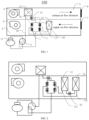
- FIG. 1 is a schematic diagram of a first embodiment of the fresh air equipment provided by the present application
- FIG. 2 is a schematic diagram of a second embodiment of the fresh air equipment provided by the present application
- FIG. 3 is a schematic diagram of the third embodiment of the fresh air equipment provided by the present application
- FIG. 4 is a schematic diagram of the fourth embodiment of the fresh air equipment provided by the present application
- FIG. 5 is a schematic diagram of the fifth embodiment of the fresh air equipment provided by the present application
- FIG. 6 is a schematic diagram of the sixth embodiment of the fresh air equipment provided by the present application.
- the fresh air equipment 100 includes a casing and a first heat exchange system 10.
- the casing is provided with an air supply channel 4.
- the first heat exchange system 10 includes: a fresh air heat exchanger structure and a first switching device; the fresh air heat exchanger structure is located in the air supply channel 4, and the fresh air heat exchanger structure has a refrigerant pipeline; the first switching device is connected with the fresh air heat exchanger structure, and the first switching device is configured to switch the flow direction of the refrigerant in the fresh air heat exchanger structure; in different operation modes of the first heat exchange system 10, the refrigerant of the first heat exchange system 10 first passes through the refrigerant pipeline located downstream of the air supply channel 4, and then passes through the refrigerant pipeline located upstream of the air supply channel 4.
- the air supply channel 4 refers to the channel through which the fresh air equipment 100 sends outdoor fresh air into the room
- the exhaust channel 5 refers to the channel through which the fresh air equipment 100 discharges indoor air to the outdoors.
- the fresh air equipment 100 in the present application may be a single flow direction fresh air equipment 100, and the single flow direction fresh air equipment 100 refers to the fresh air equipment 100 with only the air supply channel 4; or the fresh air equipment 100 may be a double flow direction fresh air equipment 100, and the double flow direction fresh air equipment 100 refers to the fresh air equipment 100 having both the air supply channel 4 and the exhaust channel 5.
- the structure of the fresh air heat exchanger can be a single heat exchanger, or it can be a plurality of heat exchangers connected in series.
- the first switching device such as a four-way valve; the four valve ports of the four-way valve are respectively connected to the compressor, the heat exchanger, the refrigerant pipeline downstream of the air supply channel 4 of the fresh air heat exchanger structure, and the refrigerant pipeline located upstream of the air supply channel 4, so that whether it is the refrigerant flowing out of the compressor or the refrigerant flowing out of the heat exchanger, must first pass through the first switching device and then flow in from the refrigerant pipeline located downstream of the air supply channel 4 of the fresh air heat exchanger structure, and flow out from the refrigerant pipeline located upstream of the air supply channel 4 of the fresh air heat exchanger structure.
- the first switching device may also be two three-way valves connected in series, or it may be four one-way valves, which are not limited here.
- the refrigerant flows in from the refrigerant pipeline downstream of the air supply channel 4 of the fresh air heat exchanger structure, and flows out from the refrigerant pipeline upstream of the air supply channel 4 of the fresh air heat exchanger structure. Its flow direction must be opposite to the air supply direction of the air supply channel 4. The heat exchange effect at this time is obviously better than the condition that the refrigerant flow direction is the same as the air supply direction of the air supply channel 4.
- the refrigerant of the first heat exchange system 10 first passes through the refrigerant pipeline located downstream of the air supply channel 4, and then passes through the refrigerant pipeline located upstream of the air supply channel 4, so that the refrigerant in the fresh air heat exchanger structure is from the downstream of the air supply channel 4 to the upstream of the air supply channel 4.
- the heat exchange capacity of fresh air equipment is improved.
- the present application also proposes a fresh air equipment 100.
- the fresh air equipment 100 includes a casing and a first heat exchange system 10.
- the casing is provided with an air supply channel 4.
- the first heat exchange system 10 includes the fresh air heat exchanger structure and the first switching device.
- the fresh air heat exchanger structure is located in the air supply channel 4.
- the fresh air heat exchanger structure has a refrigerant circulation inlet 131 and a refrigerant circulation outlet 132; the first switching device is connected to both the refrigerant circulation inlet 131 and the refrigerant circulation outlet 132, and the first switching device is configured to switch the flow direction of the refrigerant in the fresh air heat exchanger structure; In the different operation modes of the first heat exchange system 10, the refrigerant of the first heat exchange system 10 flows into the fresh air heat exchanger structure through the refrigerant circulation inlet 131, and then flows out of the fresh air heat exchanger structure through the refrigerant circulation outlet 132.
- the refrigerant of the first heat exchange system 10 flows into the fresh air heat exchanger structure through the refrigerant circulation inlet 131, and then flows out of the fresh air heat exchanger structure through the refrigerant circulation outlet 132.
- the refrigerant flow direction of the fresh air heat exchanger structure can be set to be counter-current to the air supply direction of the air supply channel 4, thereby improving the heat exchange capacity of the fresh air heat exchanger structure.
- the refrigerant flow direction of the fresh air heat exchanger structure can also be set to flow along the air supply direction of the air supply channel 4, thereby reducing the heat exchange capacity of the fresh air heat exchanger structure; for example, it turns out to be that the refrigerant flow direction in the fresh air heat exchanger structure is opposite to the air supply direction of the air supply channel 4 in the cooling mode. In the heating mode, the flow direction of the refrigerant in the the fresh air heat exchanger structure is the same as the air supply direction of the air supply channel 4.
- the refrigerant flow direction of the fresh air heat exchanger structure is set to flow in the same direction as the air supply direction of the air supply channel 4 through the first switching device, thereby reducing the cooling capacity of the fresh air heat exchanger structure.
- the refrigerant flow direction in the fresh air heat exchanger structure is the same as the air supply direction of the air supply channel 4.
- the refrigerant flow direction in the fresh air heat exchanger structure is opposite to the air supply direction of the air supply channel 4.
- the refrigerant circulation inlet 131 is located downstream of the air supply channel 4 relative to the refrigerant circulation outlet 132, so that the refrigerant flowing through the fresh air heat exchanger structure flows from the downstream of the air supply channel 4 to the upstream of the air supply channel 4, which is opposite to the air supply direction of the air supply channel 4.
- a countercurrent is formed between the two, which enhances the heat exchange capacity of the fresh air equipment.
- the fresh air heat exchanger structure is located in the first refrigerant flow path, and the first heat exchange system 10 also includes: a first compressor 11, a first heat exchange module 12 and a commutation device 3.
- the first compressor 11 is provided in the first refrigerant flow path and has a first exhaust port and a first return port;
- the first heat exchange module 12 is provided in the first refrigerant flow path and is connected with the first switching device;
- the commutation device 3 is connected with the first exhaust port, the first return port, the first heat exchange module 12 and the first switching device.
- the refrigerant device 3 is configured to switch the flow direction of the refrigerant, so that the refrigerant first passes through the first heat exchange module 12 and then passes through the first switching device, or so that the refrigerant passes through the first switching device first and then passes through the first heat exchange module 12; the first switching device communicates with the commutation device 3, the first heat exchange module 12, the refrigerant circulation inlet 131 of the fresh air heat exchanger structure, and the refrigerant circulation outlet 132 of the fresh air heat exchanger structure.
- the first switching device is configured to switch the flow direction of the refrigerant, so that the refrigerant first flows into the fresh air heat exchanger structure through the refrigerant circulation inlet 131, and then flows out of the fresh air heat exchanger structure through the refrigerant circulation outlet 132.
- the commutation device 3 there are many specific implementation forms of the commutation device 3.
- the most common one is a four-way valve, it can also be two three-way valves connected in series with each other, or it can be four one-way valves, etc.; no limitation is made here.
- the refrigerant flows out from the first exhaust port of the first compressor 11, passes through the commutation device 3, and reaches the first heat exchange module 12 for heat exchange.
- the refrigerant flows into the refrigerant circulation inlet 131 of the fresh air heat exchanger structure under the function of the first switching device.
- the refrigerant flows out from the refrigerant circulation outlet 132, then returns to the commutation device 3 through the function of the first switching device, and finally flows back into the first compressor 11 from the first return port.
- the refrigerant flows out from the first exhaust port of the first compressor 11, passes through the commutation device 3, and reaches the first switching device.
- the refrigerant flows into the refrigerant circulation inlet 131 of the fresh air heat exchanger structure; after exchanging heat through the fresh air heat exchanger structure, the refrigerant flows out from the refrigerant circulation outlet 132; after exchanging heat with the first heat exchange module 12, and after the action of the first switching device, the refrigerant returns to the commutation device 3 and flows back into the first compressor 11 from the first return port.
- the refrigerant flows in from the refrigerant circulation inlet 131 of the fresh air heat exchanger structure, and flows out from the refrigerant circulation outlet 132 after heat exchange is performed through the fresh air heat exchanger structure, thereby ensuring that the flow direction of the refrigerant in different modes within the fresh air heat exchanger structure is consistent.
- the refrigerant circulation inlet 131 and the refrigerant circulation outlet 132 can be positioned so that the flow direction of the refrigerant in the fresh air heat exchanger structure is opposite to or the same as the air supply direction of the air supply channel 4, thereby improving or reducing the heat exchange capacity of the fresh air equipment 100.
- the first compressor 11 when the fresh air equipment 100 is a single-flow fresh air equipment 100, the first compressor 11 is the outdoor unit of the fresh air equipment 100.
- the casing When the fresh air equipment 100 is a dual-flow fresh air equipment 100, the casing is also provided with an exhaust channel 5.
- the first heat exchange module 12 is installed in the exhaust channel 5.
- the first compressor 11 is installed in the exhaust channel 5 or installed outside the casing.
- the first heat exchange module 12 or the first compressor 11 is installed in the exhaust channel 5, the volume of the outdoor unit of the fresh air equipment 100 can be effectively reduced.
- the first heat exchange module 12 and the first compressor 11 are both installed in the exhaust channel 5, the outdoor unit can be directly eliminated to save space.
- the fresh air equipment 100 further includes a second heat exchange system 20.
- a second refrigerant flow path is formed on the second heat exchange system 20.
- the second heat exchange system 20 includes the second outdoor heat exchanger 21, the second compressor 27, the third fresh air heat exchanger 22 and the fourth fresh air heat exchanger 23 provided in the second refrigerant flow path.
- the third fresh air heat exchanger 22 and the fourth fresh air heat exchanger 23 are both arranged in the air supply channel 4.
- the second outdoor heat exchanger 21 and the second compressor 27 can also be arranged in the exhaust channel 5, so that the fresh air equipment 100 does not require an outdoor unit at all, thus saving space.
- the first heat exchange module 12 includes a first outdoor heat exchanger 35 and a heat recovery heat exchanger 36 arranged in series.
- the heat recovery heat exchanger 36 is arranged in the exhaust channel 5; the first outdoor heat exchanger 35 is arranged outside the casing (host casing); and the first compressor 11 is installed in the exhaust channel 5 or installed outside the casing (host casing).
- the heat recovery heat exchanger 36 is installed in the exhaust channel 5, and the air in the exhaust channel 5 is discharged from the exhaust channel 5 after heat exchange with the heat recovery heat exchanger 36, so that the air discharged from the exhaust channel 5 can be thermally recovered.
- the first switching device communicates with the commutation device 3, the heat recovery heat exchanger 36, the refrigerant circulation inlet 131 of the fresh air heat exchanger structure and the refrigerant circulation outlet 132 of the fresh air heat exchanger structure.
- the refrigerant flows out from the first exhaust port of the first compressor 11, passes through the commutation device 3, and reaches the first outdoor heat exchanger 35 of the first heat exchange module 12 and the heat recovery heat exchanger 36 in turn to perform heat exchange; after passing through the first switching device, the refrigerant flows into the refrigerant circulation inlet 131 of the fresh air heat exchanger structure; after exchanging heat through the fresh air heat exchanger structure, the refrigerant flows out from the refrigerant circulation outlet 132; and the refrigerant returns to the commutation device 3 through the action of the first switching device, and then flows back into the first compressor 11 from the first return port.
- the refrigerant flows out from the first exhaust port of the first compressor 11, passes through the commutation device 3, and flows into the refrigerant circulation inlet 131 of the the fresh air heat exchanger structure after through the action of the first switching device.
- the refrigerant flows out from the refrigerant circulation outlet 132; after the heat is exchanged by the heat recovery heat exchanger 36 of the first heat exchange module 12 and the first outdoor heat exchanger 35, the refrigerant returns to the commutation device 3 through the action of the first switching device, and flows back into the first compressor 11 from the first return port.
- the first heat exchange system 10 in order to throttle the refrigerant flowing out of the first heat exchange module 12 in the cooling mode and the refrigerant flowing into the first heat exchange module 12 in the heating mode, also includes a first throttling element 15 provided on the first refrigerant flow path.
- the first throttling element 15 is located between the first heat exchange module 12 and the first switching device, so that in the cooling mode, the refrigerant flowing out of the first heat exchange module 12 is throttled by the first throttling element 15 and then flows into the refrigerant circulation inlet 131 through the first switching device.
- the refrigerant flowing out of the refrigerant circulation outlet 132 passes through the first switching device, is throttled by the first throttling element 15 and then flows into the first heat exchange module 12, thereby realizing the control of throttling for the refrigerant flowing out from the first heat exchange module 12 in the cooling mode and the refrigerant flowing into the first heat exchange module 12 in the heating mode.
- the first switching device has a first communication port 31, a second communication port 32, an inlet port 33 and an outlet port 34.
- the fresh air heat exchanger structure communicates with the outlet port 34 and the inlet port 33.
- the first switching device includes: a first one-way valve 18, a second one-way valve 19, a third one-way valve 1 and a fourth one-way valve 2.
- the first one-way valve 18 is connected between the first communication port 31 and the inlet port 33, and the first one-way valve 18 is conductive in the direction from the inlet port 33 to the first communication port 31;
- the second one-way valve 19 is connected between the first communication port 31 and the outlet port 34, and the second one-way valve 19 is conductive in the direction from the first communication port 31 to the outlet port 34;
- the third one-way valve 1 is connected between the inlet port 33 and the second communication port 32, and the third one-way valve 1 is conductive in the direction from the inlet port 33 to the second communication port 32;
- the fourth one-way valve 2 is connected between the outlet port 34 and the second communication port 32, and the fourth one-way valve 2 is conductive in the direction from the second communication port 32 to the outlet port 34.
- the one-way valve allows fluid to flow only along the water inlet, but the medium at the water outlet cannot flow back. It is commonly known as a one-way valve.
- One-way valve is also called check valve. It is used in hydraulic systems to prevent the reverse flow of oil flow, or in pneumatic systems to prevent the reverse flow of compressed air.
- check valves There are two types of check valves: straight-through type and right-angle type.
- the straight-through check valve is installed on the pipeline with a threaded connection.
- Right-angle check valves are available in three forms: threaded connection, plate connection and flange connection.
- the one-way valve in the present application can be a spring-type one-way valve, in which the liquid moves from bottom to top and relies on pressure to push up the valve disc controlled by the spring.
- the spring force presses the valve disc down, sealing the liquid backflow.
- It can also be a gravity-type one-way valve, which is similar to the spring type and relies on the self-gravity of the valve disc to seal to prevent reverse flow, which is not limited here.
- the inlet port 33 is connected to the refrigerant circulation outlet 132, and the outlet port 34 is connected to the refrigerant circulation inlet 131;
- the first communication port 31 is connected to the first heat exchange module 12, and the second communication port 32 is connected to the first compressor 11.
- the refrigerant flows out from the first exhaust port of the first compressor 11, passes through the commutation device 3 of the first compressor 11, and reaches the first heat exchange module 12 for exchange.
- the refrigerant then flows into the refrigerant circulation inlet 131 of the fresh air heat exchanger structure through the action of the second one-way valve 19. After exchanging heat through the fresh air heat exchanger structure, the refrigerant flows out from the refrigerant circulation outlet 132; then through the action of the third one-way valve 1, the refrigerant returns to the commutation device 3 of the first compressor 11, and then flows back into the first compressor 11 from the first return port.
- the refrigerant flows out from the first exhaust port of the first compressor 11, and passes through the commutation device 3 of the first compressor 11; through the action of the fourth one-way valve 2, the refrigerant flows into the refrigerant circulation inlet 131 of the fresh air heat exchanger structure; after exchanging heat through the fresh air heat exchanger structure, the refrigerant flows out from the refrigerant circulation outlet 132; after exchanging heat with the first heat exchange module 12, and then through the action of the first one-way valve 18, the refrigerant returns to the commutation device 3 of the first compressor 11, and flows back into the first compressor 11 from the first return port.
- the outlet port 34 may also be connected to the refrigerant circulation outlet 132 of the fresh air heat exchanger structure, and the inlet port 33 may be connected to the refrigerant circulation inlet 131 of the fresh air heat exchanger structure, so that the flow direction of the refrigerant in the fresh air heat exchanger structure is the same as the air supply direction of the air supply channel 4, which weakens the heat exchange capability of the fresh air equipment 100, which is not limited here.
- the first throttling element 15 and the first one-way valve 18 are arranged in series, and the first throttling element 15 is connected and arranged between the first communication port 31 and the first one-way valve 18.
- the first throttling element 15 no longer throttles the refrigerant flowing out of the first heat exchange module 12 in the cooling mode.
- the refrigerant all flows into the fresh air heat exchanger structure to enhance its heat exchange capacity.
- the fresh air heat exchanger structure includes at least two heat exchangers connected in series to achieve reheating and dehumidification function. At this time, the reheating and dehumidification function has the best effect.
- the fresh air heat exchanger structure can have many specific forms.
- the fresh air heat exchanger can only include the first fresh air heat exchanger 13.
- the fresh air heat exchanger can also be a plurality of interconnected heat exchangers, which is not limited here.
- the fresh air heat exchanger structure includes a first fresh air heat exchanger 13 and a second fresh air heat exchanger 14 connected in series; the first fresh air heat exchanger 13 is located downstream of the air supply channel 4 opposite to the second fresh air heat exchanger 14; the outlet port 34 is connected to the first fresh air heat exchanger 13, and the inlet port 33 is connected to the second fresh air heat exchanger 14.
- the first fresh air heat exchanger 13 acts as an evaporator to cool the air
- the second fresh air heat exchanger 14 acts as a condenser to heat the air, thereby achieving the reheating and dehumidification of the air.
- the outlet port 34 is connected to the first fresh air heat exchanger 13 and the inlet port 33 is connected to the second fresh air heat exchanger 14, so that the refrigerant flows in from the refrigerant inlet of the first fresh air heat exchanger 13 and flows out through the refrigerant outlet of the second fresh air heat exchanger 14.
- the refrigerant circulation inlet 131 is the refrigerant inlet of the first fresh air heat exchanger 13
- the refrigerant circulation outlet 132 is the refrigerant outlet of the second fresh air heat exchanger 14.
- the first heat exchange system 10 also includes a second throttling element 16, and the second throttling element 16 is provided on the flow path connected in series between the first fresh air heat exchanger 13 and the second fresh air heat exchanger 14, so that the refrigerant flowing out of the first fresh air heat exchanger 13 can be throttled.
- the first heat exchange system 10 also includes a third throttling element 17, and the third throttling element 17 is located on the flow path connected between the refrigerant inlet of the second fresh air heat exchanger 14 and the first heat exchange module 12.
- the refrigerant flows through the first heat exchange module 12 to exchange heat with the hot air for cooling, and then flows through the second fresh air heat exchanger 14 to exchange heat with the indoor hot air for cooling.
- the pressure difference between the two indoor heat exchangers on the refrigerant flow path is large, and the refrigerant flowing through the first heat exchanger has higher pressure and higher temperature, so that the cooling effect is also poor.
- the third throttling element 17 is provided.
- the refrigerant can be divided into two branches in the cooling mode and flow through the first heat exchange module 12 and the second fresh air heat exchanger 14 respectively, allowing part of the pressure to be distributed to the first heat exchange module 12, so that the pressure difference between the first heat exchange module 12 and the second fresh air heat exchanger 14 decreases, thereby causing the temperature and pressure of the refrigerant flowing through the first heat exchange module 12 and the second fresh air heat exchanger 14 to decrease.
- the heat exchange refrigeration energy efficiency is higher to solve the current problem that some fresh air equipment systems with reheating and dehumidification have poor cooling effect in cooling mode.
- the fresh air equipment 100 also includes a air supply fan 6.
- the air supply fan 6 is provided in the air supply channel 4, and the air blower of the air supply fan 6 is directed indoors, so that the heat-exchanged air in the air supply channel 4 is sent into the room.
- the position of the air supply fan 6 can be any position in the air supply channel 4, as long as its air supply outlet faces the room.
- the fresh air equipment 100 may also include an air supply valve 7.
- the air supply valve 7 is provided in the air supply channel 4.
- the air supply valve 7 is configured to connect the outdoors and the air supply channel 4.
- the air supply fan 6 and the air supply valve 7 can be installed selectively. In order to pursue the best air supply effect, both of them can also be installed, which is not limited here.
- an exhaust channel 5 is also provided in the casing.
- the function of the exhaust channel 5 is to discharge indoor air to the outdoors.
- the fresh air equipment 100 also includes an exhaust fan 8, which is provided in the exhaust channel 5, and the exhaust port of the exhaust fan 8 is directed toward the outdoors, thereby exhausting indoor air to the outdoors.
- the fresh air equipment 100 may also include an exhaust valve 9.
- the exhaust valve 9 is provided at one end of the exhaust channel 5, and the exhaust valve 9 is configured to communicate with the outside.
- the exhaust fan 8 and the exhaust valve 9 can be installed alternatively. Of course, in order to pursue the best exhaust effect, both can also be installed, and there is no limitation here.
- the exhaust channel 5 includes an indoor return air outlet and an outdoor exhaust outlet
- the air supply channel 4 includes an outdoor air inlet and an indoor air supply outlet.
- the exhaust fan 8 is provided close to the indoor return air outlet; the exhaust valve 9 is set at the outdoor exhaust outlet; the air supply fan 6 is set close to the indoor air supply outlet; and the air supply valve 7 is set at the outdoor air inlet.
- the exhaust fan 8 is provided close to the indoor return air outlet, and can directly discharge the indoor air from the exhaust channel 5 through the indoor return air outlet.
- the air supply fan 6 is provided close to the indoor air supply outlet, which can directly send the fresh air in the air supply channel 4 into the room from the indoor air supply outlet.
- the exhaust valve 9 is set at the outdoor exhaust outlet, and the opening and closing of the exhaust channel 5 can be controlled only by controlling the opening and closing of the exhaust valve 9.
- the exhaust valve 9 is set at the outdoor exhaust outlet, and only the opening and closing of the air supply valve 7 can be controlled to control the opening and closing of the air supply channel 4.
- the casing is formed with a communication port that connects the exhaust channel 5 and the air supply channel 4, and the communication port is located upstream of the fresh air heat exchanger structure and located upstream of the heat recovery heat exchanger 36.
- the fresh air equipment 100 also includes a bypass ventilation valve 30.
- the bypass ventilation valve 30 is provided at the communication port, so that the exhaust channel 5 and the air supply channel 4 can be connected through the communication port, and the bypass ventilation valve 30 is provided at the communication port.
- the bypass valve is closed and the air supply valve 7 is opened, so that the fresh air enters the room from the indoor air supply port.
- the air supply valve 7 can be closed to prevent outdoor fresh air from entering the air supply channel 4 from the outdoor air inlet, and then the bypass ventilation valve 30 can be opened.
- the heat exchanged air in the air supply channel 4 is the air discharged from the room into the exhaust channel 5 to achieve cyclic heat exchange of the indoor air and quickly heat or cool the indoor air.
- the exhaust valve 9 can also be closed to completely isolate indoor and outdoor air, which can achieve better cooling or heating effects and achieve internal circulation of indoor air.
- the fresh air equipment 100 also includes a second heat exchange system 20.
- a second refrigerant flow path is formed on the second heat exchange system 20.
- the second heat exchange system 20 includes a second outdoor heat exchanger 21, a third fresh air heat exchanger 22 and a fourth fresh air heat exchanger 23 which are sequentially arranged in series in the second refrigerant flow path.
- the third fresh air heat exchanger 22 and the fourth fresh air heat exchanger 23 are both located in the air supply channel 4.
- the upstream heat exchange system can preheat or precool the air, and then get through the heat exchange of the downstream heat exchange system. At this time, it can effectively reduce the outlet air temperature in the cooling mode, and increase the outlet air temperature in the heating mode.
- the upstream heat exchange system can also cool the air, and the downstream heat exchange system can heat the air, thereby realizing the reheating and dehumidification function.
- the second heat exchange system 20 further includes a second switching device for switching the second outdoor heat exchanger 21 to connect to the third fresh air heat exchanger 22, or to simultaneously connect to the third fresh air heat exchanger 22 and the fourth fresh air heat exchanger 23.
- the second switching device can have many specific forms, and can be a four-way valve.
- the four valve ports of the four-way valve are respectively connected to the two communication ports of the third fresh air heat exchanger 22 and the fourth fresh air heat exchanger 23 and the second outdoor heat exchanger 21.
- the two communication ports of the third fresh air heat exchanger 22 are directly connected, or the two communication ports of the third fresh air heat exchanger are directly closed.
- the second outdoor heat exchanger 21 and the fourth fresh air heat exchanger 23 are connected.
- the refrigerant flows out from the second compressor 27, passes through the four-way valve of the second compressor 27, and reaches the fourth fresh air heat exchanger 23.
- the refrigerant of the second compressor 27 flows out of the second compressor 27, passes through the four-way valve of the second compressor 27, the second outdoor heat exchanger 21, the third fresh air heat exchanger 22 and the fourth fresh air heat exchanger 23 in sequence, and returns to the four-way valve of the second compressor 27 and flows back to the second compressor 27 to complete the refrigeration cycle.
- the second switching device may also be a combination of a throttling element and a one-way valve, or a combination of two throttling elements, etc., which is not limited here.
- the second outdoor heat exchanger 21 is simultaneously connected with the fourth fresh air heat exchanger 23 and the third fresh air heat exchanger 22 to realize the reheating and dehumidification function or the cooling function.
- the second outdoor heat exchanger 21 is connected with the fourth fresh air heat exchanger 23, so that the refrigerant no longer passes through the third heat exchanger 22, thereby preventing the third heat exchanger 22 from cooling the air, improving the heating effect of the fresh air equipment 100, and also reducing the energy consumption of the fresh air equipment 100 in the heating mode.
- the arrangement direction of the third fresh air heat exchanger 22 and the fourth fresh air heat exchanger 23 is opposite to the air supply direction of the air supply channel 4.
- the flow direction of the refrigerant flowing through the third fresh air heat exchanger 22 and the fourth fresh air heat exchanger 23 is opposite to the air supply direction of the air supply channel 4.
- a counterflow occurs between the refrigerant and the air, which enhances the heat exchange capabilities of the third fresh air heat exchanger 22 and the fourth fresh air heat exchanger 23.
- a downstream flow is formed between the refrigerant in the fourth fresh air heat exchanger 23 and the air in the air supply channel 4, but at this time, the refrigerant no longer passes through the third fresh air heat exchanger 22, which avoids the influence of the third fresh air heat exchanger 22 on the air, thereby improving the cooling and heating capabilities of the fresh air equipment 100, and reducing the energy consumption of the fresh air equipment 100 in the heating mode.
- the second switching device can have many specific forms, and can be a combination of a throttling element and a one-way valve, or a combination of two throttling elements, etc.
- the second switching device includes a fourth throttling element 24 and a fifth one-way valve 25 (the fifth one-way valve 25 can be replaced by a solenoid valve);
- the fourth throttling element 24 is provided on the second refrigerant flow path, and between the third fresh air heat exchanger 22 and the fourth fresh air heat exchanger 23;
- the fifth one-way valve 25, the third fresh air heat exchanger 22 and the fourth throttling element 24 are arranged in parallel, and the conduction direction of the fifth one-way valve 25 is from the fourth fresh air heat exchanger 23 to the second outdoor heat exchanger 21.
- the refrigerant flows out from the second compressor 27 and reaches the third fresh air heat exchanger 22 via the second outdoor heat exchanger 21 for heat exchange, then throttles through the fourth throttling element 24, reaches the fourth fresh air heat exchanger 23 for heat exchange, and then returns to the second compressor 27 to complete the refrigeration cycle.
- the fourth throttling element 24 is closed; the refrigerant flows out from the second compressor 27, and directly flows into the fourth fresh air heat exchanger 23 through the fifth one-way valve 25; the refrigerant flows into the second outdoor heat exchanger 21 after exchanging heat through the fourth fresh air heat exchanger 23, and finally returns to the second compressor 27 to complete the refrigeration cycle.
- the fifth one-way valve 25 can also be replaced with a throttling element.
- the throttling element In the cooling or reheating dehumidification mode, the throttling element is closed. In the heating mode, the fourth throttling element 24 is closed, and the fifth one-way valve 25 is opened and replaced, so that the same effect can be achieved.
- the fifth one-way valve 25 can also be replaced with a solenoid valve.
- the solenoid valve In the cooling or reheating and dehumidification mode, the solenoid valve is closed.
- the fourth throttling element 24 In the heating mode, the fourth throttling element 24 is closed, and opened to replace the the solenoid valve of the fifth one-way valve 25, so that the same effect can be achieved.
- the refrigerant flows through the first heat exchanger to exchange heat with the hot air for cooling, and then flows through the second heat exchanger to exchange heat with indoor hot air for cooling.
- the pressure difference between the two indoor heat exchangers on the refrigerant flow path is larger; the pressure of the refrigerant flowing through the first heat exchanger is larger and the temperature is higher; and its cooling effect is also poor.
- the fifth one-way valve 25 is replaced with a throttling element.
- the refrigerant can be divided into two branches in the cooling mode.
- the refrigerant flows through the third fresh air heat exchanger 22 and the fourth fresh air heat exchanger 23 respectively, so that part of the pressure is distributed to the third fresh air heat exchanger 22, so that the pressure difference between the third fresh air heat exchanger 22 and the fourth fresh air heat exchanger 23 decreases, causing the temperature and pressure of the refrigerant flowing through the third fresh air heat exchanger 22 and the fourth fresh air heat exchanger 23 to decrease.
- heat exchange refrigeration is more energy efficient to solve the problem of poor cooling effect in existing reheating and dehumidification fresh air equipment systems in the cooling mode.
- the second heat exchange system 20 In order to throttle the refrigerant flowing out of the second outdoor heat exchanger 21 in the cooling mode or the reheating and dehumidification mode, the second heat exchange system 20 also includes a fifth throttling element 26.
- the fifth throttling element 26 is provided on the second refrigerant flow path and between the third fresh air heat exchanger 22 and the second outdoor heat exchanger 21.
- the refrigerant flowing out of the second outdoor heat exchanger 21 enters the third fresh air heat exchanger 22 through the throttling of the fifth throttling element 26.
- the fifth one-way valve 25 may be connected between the third fresh air heat exchanger 22 and the fourth throttling element 24.
- the fifth one-way valve 25 is connected between the second outdoor heat exchanger 21 and the fourth throttling element 24; the refrigerant flowing out of the fourth fresh air heat exchanger 23, without throttling by the fifth throttling element 26, enters the second outdoor heat exchanger 21, and returns to the second compressor 27.
- the casing is also provided with an exhaust channel 5, and the second outdoor heat exchanger 21 is installed in the exhaust channel 5; and/or, the second compressor 27 is installed in the exhaust channel 5.
- the second outdoor heat exchanger 21 or the second compressor 27 is installed in the exhaust channel 5
- the volume of the outdoor unit of the fresh air equipment 100 can be effectively reduced.
- the second outdoor heat exchanger 21 and the second compressor 27 are both installed in the exhaust channel 5, the outdoor unit can be directly eliminated to save space.
- first outdoor heat exchanger 35 and the first compressor 11 of the first heat exchange system and the second outdoor heat exchanger 21 and the second compressor 27 of the second heat exchange system are all arranged in the exhaust channel 5, so there is no need to install an outdoor unit of the fresh air equipment.
- the second fresh air heat exchanger 14 is located between the third fresh air heat exchanger 22 and the fourth fresh air heat exchanger 23.
- the air achieves three heat exchanges in the air supply channel 4, which can improve the cooling energy efficiency of the fresh air equipment 100, or improve the reheating capacity of the fresh air equipment 100.
- the first fresh air heat exchanger 13 and the third fresh air heat exchanger 22 can also be arranged in parallel in the width direction or height direction of the air supply channel 4, thereby effectively reducing the volume of the fresh air equipment 100.
- first fresh air heat exchanger 13 and the third fresh air heat exchanger 22 jointly block the cross section of the air supply channel 4 at the first fresh air heat exchanger 13.
- first fresh air heat exchanger 13 and the third fresh air heat exchanger 22 simultaneously exchange heat for the air in the air supply channel 4, and jointly shield the cross section of the air supply channel 4 at the first fresh air heat exchanger 13, thereby ensuring that the air flowing through the air supply channel 4 exchanges heat with at least one of the first fresh air heat exchanger 13 or the third fresh air heat exchanger 22.
- the second fresh air heat exchanger 14 between the third fresh air heat exchanger 22 and the fourth fresh air heat exchanger 23, and the first fresh air heat exchanger 13 and the third fresh air heat exchanger 22 are arranged in parallel in the width direction of the air supply channel 4.
- the first fresh air heat exchanger 13 and the third fresh air heat exchanger 22 jointly block the cross section of the air supply channel 4 at the first fresh air heat exchanger 13.
- the first fresh air heat exchanger 13 and the third fresh air heat exchanger 22 form a heat exchange module, and the cross-sectional area of the heat exchange module, the cross-sectional area of the second fresh air heat exchanger 14 and the cross-sectional area of the fourth fresh air heat exchangers 23 are equal.
- the cross-sectional area of the second fresh air heat exchanger 14 is larger than the cross-sectional area of the third fresh air heat exchanger 22.
- the casing includes a main body casing and an outdoor unit casing.
- the air supply channel 4 and the exhaust channel 5 are provided in the main body casing.
- the first heat exchange system 10 also includes a first compressor 11 and the first heat exchange module 12.
- the first heat exchange module 12 includes a first outdoor heat exchanger 35 and a heat recovery heat exchanger arranged in series; the heat recovery heat exchanger is arranged in the exhaust channel 5, and the fourth fresh air heat exchanger 23 is arranged in the air supply channel 4; the first compressor 11, the first outdoor heat exchanger 35, the second compressor 27, the second outdoor heat exchanger 21 and the outdoor fan 37 are all arranged in the outdoor unit casing.
- the heat recovery heat exchanger is arranged in the exhaust channel 5; the fourth fresh air heat exchanger 23 is arranged in the air supply channel 4; the first compressor 11, the first outdoor heat exchanger 35, the second compressor 27, the second outdoor heat exchanger 21 and the outdoor fan 37 are all arranged in the outdoor unit casing; the components of a part of the outdoor unit are arranged in the exhaust channel 5, and the remaining components are arranged in the casing of the outdoor unit. Only one outdoor unit is needed to satisfy the first heat exchange system 10 and the second heat exchange system 20, which reduces the space occupied by the outdoor unit and also reduces the workload of installing the outdoor unit.
- the first outdoor heat exchanger 35 and the second outdoor heat exchanger 21 are connected and arranged opposite to the outdoor fan 37.
- the first outdoor heat exchanger 35 is arranged on the second outdoor heat exchanger 21 as a whole, and the outdoor fan 37 dissipates heat to the whole. Only one outdoor fan 37 is needed to dissipate heat to two outdoor heat exchangers at the same time.
- the first outdoor heat exchanger 35 can be provided at the top, bottom or side of the second outdoor heat exchanger 21, and the outdoor fan 37 is configured to dissipate heat to the first outdoor heat exchanger 35 and the second outdoor heat exchanger 21 at the same time.
Landscapes
- Engineering & Computer Science (AREA)
- Chemical & Material Sciences (AREA)
- Combustion & Propulsion (AREA)
- Mechanical Engineering (AREA)
- General Engineering & Computer Science (AREA)
- Signal Processing (AREA)
- Physics & Mathematics (AREA)
- Fuzzy Systems (AREA)
- Mathematical Physics (AREA)
- Other Air-Conditioning Systems (AREA)
Abstract
Description
- The present application claims priority to
Chinese Patent Applications Nos. 202210733516.1 202221591296.5 202221614490.0, all filed on June 23, 2022 - The present application relates to the technical field of air conditioning equipment, in particular to a fresh air equipment.
- Existing fresh air equipment mainly consists of an indoor heat exchanger, a compressor and an outdoor heat exchanger to form a refrigerant circuit. In the cooling mode, the refrigerant flowing out of the compressor returns to the compressor through the outdoor heat exchanger and the indoor heat exchanger. In the heating mode, the refrigerant flowing out of the compressor returns to the compressor through the indoor heat exchanger and the outdoor heat exchanger. In the cooling and heating modes, the refrigerant flowing through the indoor heat exchanger flows in the opposite direction, which will cause that in a certain mode, the refrigerant flowing through the indoor heat exchanger is consistent with the air supply direction, while in another mode, the refrigerant flowing through the indoor heat exchanger is opposite to the air supply direction, which will affect the heat transfer capacity of the fresh air equipment.
- The main purpose of the present application is to propose a fresh air equipment, aiming to solve the problem that existing indoor heat exchangers have different refrigerant flow directions in different modes.
- In order to achieve the above purpose, the present application proposes a fresh air equipment, comprising:
- a casing; and
- a first heat exchange system;
- an air supply channel is provided in the casing, and the first heat exchange system comprises:
- a fresh air heat exchanger structure; the fresh air heat exchanger structure is located in the air supply channel, and the fresh air heat exchanger structure is provided with a refrigerant pipeline; and
- a first switching device; the first switching device is communicated with the fresh air heat exchanger structure, and the first switching device is configured to switch a flow direction of refrigerant in the fresh air heat exchanger structure;
- in different operation modes of the first heat exchange system, the refrigerant of the first heat exchange system is first configured to pass through the refrigerant pipeline located downstream of the air supply channel, and then configured to pass through the refrigerant pipeline located upstream of the air supply channel.
- In order to achieve the above purpose, the present application also proposes a fresh air equipment, comprising:
- a casing; and
- a first heat exchange system;
- an air supply channel is provided in the casing, and the first heat exchange system comprises:
- a fresh air heat exchanger structure; the fresh air heat exchanger structure is located in the air supply channel, and the fresh air heat exchanger structure is provided with a refrigerant circulation inlet and a refrigerant circulation outlet; and
- a first switching device; the first switching device is communicated with both the refrigerant circulation inlet and the refrigerant circulation outlet, and the first switching device is configured to switch a flow direction of refrigerant in the fresh air heat exchanger structure;
- in different operation modes of the first heat exchange system, the refrigerant of the first heat exchange system is configured to flow into the fresh air heat exchanger structure through the refrigerant circulation inlet, and then configured to flow out of the fresh air heat exchanger structure through the refrigerant circulation outlet.
- In an embodiment, the refrigerant circulation inlet is located downstream of the air supply channel relative to the refrigerant circulation outlet.
- In an embodiment, a first refrigerant flow path is formed in the first heat exchange system; the fresh air heat exchanger structure is located in the first refrigerant flow path, and the first heat exchange system further comprises:
- a first compressor disposed in the first refrigerant flow path and provided with a first exhaust port and a first return port;
- a first heat exchange module provided in the first refrigerant flow path and communicated with the first switching device; and
- a commutation device communicated with the first exhaust port, the first return port, the first heat exchange module and the first switching device; the commutation device is configured to switch the flow direction of the refrigerant so that the refrigerant is first configured to pass through the first heat exchange module and then configured to pass through the first switching device, or, so that the refrigerant is first configured to pass through the first switching device and then configured to pass through the first heat exchange module;
- the first switching device is communicated with the commutation device, the first heat exchange module, the refrigerant circulation inlet of the fresh air heat exchanger structure, and the refrigerant circulation outlet of the fresh air heat exchanger structure; the first switching device is configured to switch the flow direction of the refrigerant, so that the refrigerant is first configured to flow into the fresh air heat exchanger structure through the refrigerant circulation inlet, and then configured to flow out of the fresh air heat exchanger structure through the refrigerant circulation outlet.
- In an embodiment, the casing is further provided with an exhaust channel; the first heat exchange module is installed in the exhaust channel, and the first compressor is installed in the exhaust channel or installed outside the casing.
- In an embodiment, the air supply channel is such a channel that is configured to send outdoor fresh air into indoors by the fresh air equipment, and the exhaust channel is such a channel that is configured to discharge indoor air to outdoors by the fresh air equipment.
- In an embodiment, the casing is further provided with an exhaust channel, and the first heat exchange module comprises a first outdoor heat exchanger and a heat recovery heat exchanger arranged in series; the heat recovery heat exchanger is arranged in the exhaust channel, and the first outdoor heat exchanger is arranged outside the casing; the first compressor is installed in the exhaust channel or outside the casing.
- In an embodiment, the first heat exchange system further comprises a first throttling element provided in the first refrigerant flow path, and the first throttling element is located between the first heat exchange module and the first switching device.
- In an embodiment, the first switching device comprises a first communication port, a second communication port, an inlet port and an outlet port, and the fresh air heat exchanger structure is communicated with the outlet port and the inlet port; the first switching device comprises:
- a first one-way valve connected between the first communication port and the inlet port; the first one-way valve is configured to conduct in a direction from the inlet port to the first communication port;
- a second one-way valve connected between the first communication port and the outlet port; the second one-way valve is configured to conduct in a direction from the first communication port to the outlet port;
- a third one-way valve connected between the inlet port and the second communication port; the third one-way valve is configured to conduct in a direction from the inlet port to the second communication port; and
- a fourth one-way valve connected between the outlet port and the second communication port; the fourth one-way valve is configured to conduct in a direction from the second communication port to the outlet port.
- In an embodiment, the first heat exchange system further comprises a first throttling element; the first throttling element and the first one-way valve are arranged in series, and the first throttling element is provided between the first communication port and the first one-way valve.
- In an embodiment, the outlet port is communicated to the refrigerant circulation inlet of the fresh air heat exchanger structure, and the inlet port is communicated to the refrigerant circulation outlet of the fresh air heat exchanger structure; the first communication port is communicated to the first heat exchange module, and the second communication port is communicated to the first compressor.
- In an embodiment, the fresh air heat exchanger structure comprises a first fresh air heat exchanger and a second fresh air heat exchanger arranged in series, and the first fresh air heat exchanger is located downstream of the air supply channel relative to the second fresh air heat exchanger; the outlet port is connected to the first fresh air heat exchanger, and the inlet port is connected to the second fresh air heat exchanger.
- In an embodiment, the first heat exchange system further comprises a second throttling element, and the second throttling element is provided on a flow path connected in series between the first fresh air heat exchanger and the second fresh air heat exchanger.
- In an embodiment, the first heat exchange system further comprises a third throttling element, and the third throttling element is located on a flow path communicated between the refrigerant inlet of the second fresh air heat exchanger and the first communication port.
- In an embodiment, the casing is further provided with an exhaust channel;
- the fresh air equipment also comprises an exhaust fan; the exhaust fan is provided in the exhaust channel, and the exhaust fan is configured to exhaust air outdoors; and/or
- the fresh air equipment also comprises an exhaust valve, and the exhaust valve is provided in the exhaust channel; and/or
- the fresh air equipment also comprises an air supply fan; the air supply fan is provided in the air supply channel, and the air supply fan is configured to blow air indoors; and/or
- the fresh air equipment also comprises an air supply valve, and the air supply valve is provided in the air supply channel.
- In an embodiment, the exhaust channel comprises an indoor return air outlet and an outdoor exhaust outlet, and the air supply channel comprises an outdoor air inlet and an indoor air supply outlet; the exhaust fan is provided close to the indoor return air outlet, and the exhaust valve is arranged at the outdoor exhaust outlet; the air supply fan is arranged close to the indoor air supply outlet, and the air supply valve is arranged at the outdoor air inlet.
- In an embodiment, the casing is formed with a communication port communicating the exhaust channel and the air supply channel, and the communication port is located upstream of the fresh air heat exchanger structure; the fresh air equipment also comprises a bypass ventilation valve, and the bypass ventilation valve is provided at the communication port.
- In order to achieve the above purpose, the present application also proposes a fresh air equipment, comprising: a casing and a second heat exchange system; an air supply channel is provided in the casing, and a second refrigerant flow path is formed on the second heat exchange system; the second heat exchange system comprises:
- a second outdoor heat exchanger, a third fresh air heat exchanger and a fourth fresh air heat exchanger arranged in the second refrigerant flow path; the third fresh air heat exchanger and the fourth fresh air heat exchanger are both arranged in the air supply channel; and
- a second switching device configured to switch the second outdoor heat exchanger to communicate with the third fresh air heat exchanger ,or configured to communicate with the third fresh air heat exchanger and the fourth fresh air heat exchanger at the same time.
- In an embodiment, the second switching device further comprises a fourth throttling element and a fifth one-way valve; the fourth throttling element is provided on the second refrigerant flow path, and located between the third fresh air heat exchanger and the fourth fresh air heat exchanger; and
the fifth one-way valve is arranged in parallel with the third fresh air heat exchanger and the fourth throttling element, and a conducting direction of the fifth one-way valve is from the fourth fresh air heat exchanger to the second outdoor heat exchanger. - In an embodiment, the second switching device further comprises a fourth throttling element and a fifth one-way valve; the fourth throttling element is provided on the second refrigerant flow path, and the fifth one-way valve is communicated between the second outdoor heat exchanger and the fourth throttling element.
- In an embodiment, the second heat exchange system further comprises a fifth throttling element, and the fifth throttling element is provided on the second refrigerant flow path and located between the third fresh air heat exchanger and the second outdoor heat exchanger.
- In an embodiment, an arrangement direction of the third fresh air heat exchanger and the fourth fresh air heat exchanger is opposite to an air supply direction of the air supply channel.
- In an embodiment, the casing is further provided with an exhaust channel, and the second heat exchange system further comprises a second compressor provided on the second refrigerant flow path; and
the second outdoor heat exchanger is installed in the exhaust channel, and the second compressor is installed in the exhaust channel or outside the casing. - In an embodiment, the fresh air equipment further comprises a first heat exchange system; the first heat exchange system comprises a fresh air heat exchanger structure and a first switching device, and the fresh air heat exchanger structure is located in the air supply channel;
- the fresh air heat exchanger structure comprises a first fresh air heat exchanger and a second fresh air heat exchanger arranged in series;
- the second fresh air heat exchanger is located between the third fresh air heat exchanger and the fourth fresh air heat exchanger; and/or
- the first fresh air heat exchanger and the third fresh air heat exchanger are arranged in parallel in a width direction or height direction of the air supply channel; and/or
- the first fresh air heat exchanger and the third fresh air heat exchanger are configured to jointly block a cross section of the air supply channel at the first fresh air heat exchanger.
- In an embodiment, the fresh air equipment further comprises a first heat exchange system, and the first heat exchange system comprises:
- a fresh air heat exchanger structure located in the air supply channel; the fresh air heat exchanger structure is provided with a refrigerant pipeline; and
- a first switching device communicated to the fresh air heat exchanger structure; the first switching device is configured to switch a flow direction of the refrigerant in the fresh air heat exchanger structure;
- in different operation modes of the first heat exchange system, the refrigerant of the first heat exchange system is first configured to pass through the refrigerant pipeline located downstream of the air supply channel, and then configured to pass through the refrigerant pipeline located upstream of the air supply channel.
- In an embodiment, the fresh air equipment further comprises:
- a first heat exchange system; the first heat exchange system comprises: a fresh air heat exchanger structure located in the air supply channel; the fresh air heat exchanger structure is provided with a refrigerant circulation inlet and a refrigerant circulation outlet; and a first switching device communicated to both the refrigerant circulation inlet and the refrigerant circulation outlet; the first switching device is configured to switch a flow direction of the refrigerant in the fresh air heat exchanger structure;
- in different operation modes of the first heat exchange system, the refrigerant of the first heat exchange system is configured to flow into the fresh air heat exchanger structure through the refrigerant circulation inlet, and then configured to flow out of the fresh air heat exchanger structure through the refrigerant circulation outlet.
- In an embodiment, the fresh air equipment further comprises:
- a second heat exchange system; and
- an outdoor fan;
- the second heat exchange system comprises a second compressor, a second outdoor heat exchanger and a fourth fresh air heat exchanger;
- the casing comprises a main body casing and an outdoor unit casing, and the air supply channel and the exhaust channel are provided in the main body casing;
- the first heat exchange system also comprises a first compressor and a first heat exchange module, and the first heat exchange module comprises a first outdoor heat exchanger and a heat recovery heat exchanger arranged in series;
- the heat recovery heat exchanger is arranged in the exhaust channel, and the fourth fresh air heat exchanger is arranged in the air supply channel; and
- the first compressor, the first outdoor heat exchanger, the second compressor, the second outdoor heat exchanger and the outdoor fan are arranged in the outdoor unit casing, and the first outdoor heat exchanger and the second outdoor heat exchanger are connected and arranged opposite to the outdoor fan.
- In the technical solution provided by the present application, by arranging a first switching device, in different operation modes, the refrigerant of the first heat exchange system first passes through the refrigerant pipeline located downstream of the air supply channel, and then passes through the refrigerant pipeline located upstream of the air supply channel, so that the refrigerant flows from the downstream of the air supply channel to the upstream of the air supply channel in the fresh air heat exchanger structure.
- In order to more clearly illustrate the technical solutions in the embodiments of the present application or the related art, the following will briefly introduce the drawings that need to be used in the description of the embodiments or the related art. Obviously, the accompanying drawings in the following description are only some embodiments of the present application, and those skilled in the art can also obtain other drawings according to the structures shown in these drawings without creative effort.
-
FIG. 1 is a schematic diagram of the fresh air equipment according to a first embodiment of the present application. -
FIG. 2 is a schematic diagram of the fresh air equipment according to a second embodiment of the present application. -
FIG. 3 is a schematic diagram of the fresh air equipment according to a third embodiment of the present application. -
FIG. 4 is a schematic diagram of the fresh air equipment according to a fourth embodiment of the present application. -
FIG. 5 is a schematic diagram of the fresh air equipment according to a fifth embodiment of the present application. -
FIG. 6 is a schematic diagram of the fresh air equipment according to a sixth embodiment of the present application. -
reference sign name reference sign name 100 fresh air equipment 10 first heat exchange system 20 second heat exchange system 11 first compressor 12 first heat exchange module 13 first fresh air heat exchanger 14 second fresh air heat exchanger 131 refrigerant circulation inlet 132 refrigerant circulation outlet 15 first throttling element 16 second throttling element 17 third throttling element 18 first one- way valve 19 second one- way valve 1 third one- way valve 2 fourth one- way valve 3 commutation device 4 air supply channel 5 exhaust channel 6 air supply fan 7 air supply valve 8 exhaust fan 9 exhaust valve 27 second compressor 21 second outdoor heat exchanger 22 third fresh air heat exchanger 23 fourth fresh air heat exchanger 24 fourth throttling element 25 fifth one- way valve 26 fifth throttling element 30 bypass ventilation valve 31 first communication port 32 second communication port 33 inlet port 34 outlet port 35 first outdoor heat exchanger 36 heat recovery heat exchanger 37 outdoor fan - The realization, functional features and advantages of the present application will be further described in conjunction with the embodiments and with reference to the accompanying drawings.
- The following will clearly and completely describe the technical solutions in the embodiments of the present application with reference to the accompanying drawings in the embodiments of the present application. Obviously, the described embodiments are only part of the embodiments of the present application, not all of them. Based on the embodiments in the present application, all other embodiments obtained by those skilled in the art without creative efforts fall within the protection scope of the present application.
- It should be noted that if there is a directional indication (such as up, down, left, right, front, back...) in the embodiment of the present application, the directional indication is only configured to explain the relationship between the components in a certain posture. If the specific posture changes, the directional indication will also change accordingly.
- In addition, if there are descriptions involving "first", "second", etc. in the embodiments of the present application, the descriptions of "first", "second", etc. are only for descriptive purposes, and cannot be understood as indicating or implying their relative importance or implicitly indicating the number of indicated technical features. Thus, the features defined as "first" and "second" may explicitly or implicitly include at least one of these features. In addition, if "and/or" appears throughout the text, its meaning includes three parallel plans, taking "A and/or B" as an example, including plan A, or plan B, or A and B is a solution that is satisfied at the same time. In addition, the technical solutions of the various embodiments can be combined with each other, but it must be based on the realization of those skilled in the art. When the combination of technical solutions is contradictory or cannot be realized, it should be considered that the combination of technical solutions does not exist, nor within the protection scope required by the present application.
- Existing fresh air equipment mainly consists of an indoor heat exchanger, a compressor and an outdoor heat exchanger to form a refrigerant circuit. In the cooling mode, the refrigerant flowing out of the compressor returns to the compressor through the outdoor heat exchanger and the indoor heat exchanger. In the heating mode, the refrigerant flowing out of the compressor returns to the compressor through the indoor heat exchanger and the outdoor heat exchanger. In the cooling and heating modes, the refrigerant flowing through the indoor heat exchanger flows in the opposite direction, which will cause that in a certain mode, the refrigerant flowing through the indoor heat exchanger is consistent with the air supply direction, while in another mode, the refrigerant flowing through the indoor heat exchanger is opposite to the air supply direction, which will affect the heat transfer capacity of the fresh air equipment.
- In order to solve the above problems, the present application provides a
fresh air equipment 100.FIG. 1 is a schematic diagram of a first embodiment of the fresh air equipment provided by the present application;FIG. 2 is a schematic diagram of a second embodiment of the fresh air equipment provided by the present application;FIG. 3 is a schematic diagram of the third embodiment of the fresh air equipment provided by the present application;FIG. 4 is a schematic diagram of the fourth embodiment of the fresh air equipment provided by the present application;FIG. 5 is a schematic diagram of the fifth embodiment of the fresh air equipment provided by the present application;FIG. 6 is a schematic diagram of the sixth embodiment of the fresh air equipment provided by the present application. - Please referring to
FIGS. 1 to 6 , thefresh air equipment 100 includes a casing and a firstheat exchange system 10. The casing is provided with anair supply channel 4. The firstheat exchange system 10 includes: a fresh air heat exchanger structure and a first switching device; the fresh air heat exchanger structure is located in theair supply channel 4, and the fresh air heat exchanger structure has a refrigerant pipeline; the first switching device is connected with the fresh air heat exchanger structure, and the first switching device is configured to switch the flow direction of the refrigerant in the fresh air heat exchanger structure; in different operation modes of the firstheat exchange system 10, the refrigerant of the firstheat exchange system 10 first passes through the refrigerant pipeline located downstream of theair supply channel 4, and then passes through the refrigerant pipeline located upstream of theair supply channel 4. - It should be noted that the
air supply channel 4 refers to the channel through which thefresh air equipment 100 sends outdoor fresh air into the room, and theexhaust channel 5 refers to the channel through which thefresh air equipment 100 discharges indoor air to the outdoors. Thefresh air equipment 100 in the present application may be a single flow directionfresh air equipment 100, and the single flow directionfresh air equipment 100 refers to thefresh air equipment 100 with only theair supply channel 4; or thefresh air equipment 100 may be a double flow directionfresh air equipment 100, and the double flow directionfresh air equipment 100 refers to thefresh air equipment 100 having both theair supply channel 4 and theexhaust channel 5. - The structure of the fresh air heat exchanger can be a single heat exchanger, or it can be a plurality of heat exchangers connected in series. There is no limitation here. There can be many specific implementation forms of the first switching device, such as a four-way valve; the four valve ports of the four-way valve are respectively connected to the compressor, the heat exchanger, the refrigerant pipeline downstream of the
air supply channel 4 of the fresh air heat exchanger structure, and the refrigerant pipeline located upstream of theair supply channel 4, so that whether it is the refrigerant flowing out of the compressor or the refrigerant flowing out of the heat exchanger, must first pass through the first switching device and then flow in from the refrigerant pipeline located downstream of theair supply channel 4 of the fresh air heat exchanger structure, and flow out from the refrigerant pipeline located upstream of theair supply channel 4 of the fresh air heat exchanger structure. In the same way, the first switching device may also be two three-way valves connected in series, or it may be four one-way valves, which are not limited here. - Moreover, it needs to be emphasized that the refrigerant flows in from the refrigerant pipeline downstream of the
air supply channel 4 of the fresh air heat exchanger structure, and flows out from the refrigerant pipeline upstream of theair supply channel 4 of the fresh air heat exchanger structure. Its flow direction must be opposite to the air supply direction of theair supply channel 4. The heat exchange effect at this time is obviously better than the condition that the refrigerant flow direction is the same as the air supply direction of theair supply channel 4. - In any embodiment, by arranging the first switching device, in different operation modes, the refrigerant of the first
heat exchange system 10 first passes through the refrigerant pipeline located downstream of theair supply channel 4, and then passes through the refrigerant pipeline located upstream of theair supply channel 4, so that the refrigerant in the fresh air heat exchanger structure is from the downstream of theair supply channel 4 to the upstream of theair supply channel 4. Compared with traditional fresh air equipment solutions, the heat exchange capacity of fresh air equipment is improved. - At the same time, the present application also proposes a
fresh air equipment 100. Thefresh air equipment 100 includes a casing and a firstheat exchange system 10. The casing is provided with anair supply channel 4. The firstheat exchange system 10 includes the fresh air heat exchanger structure and the first switching device. The fresh air heat exchanger structure is located in theair supply channel 4. The fresh air heat exchanger structure has arefrigerant circulation inlet 131 and arefrigerant circulation outlet 132; the first switching device is connected to both therefrigerant circulation inlet 131 and therefrigerant circulation outlet 132, and the first switching device is configured to switch the flow direction of the refrigerant in the fresh air heat exchanger structure; In the different operation modes of the firstheat exchange system 10, the refrigerant of the firstheat exchange system 10 flows into the fresh air heat exchanger structure through therefrigerant circulation inlet 131, and then flows out of the fresh air heat exchanger structure through therefrigerant circulation outlet 132. - In any embodiment, under different operation modes of the first
heat exchange system 10, the refrigerant of the firstheat exchange system 10 flows into the fresh air heat exchanger structure through therefrigerant circulation inlet 131, and then flows out of the fresh air heat exchanger structure through therefrigerant circulation outlet 132. With this arrangement, the refrigerant flow direction of the fresh air heat exchanger structure can be set to be counter-current to the air supply direction of theair supply channel 4, thereby improving the heat exchange capacity of the fresh air heat exchanger structure. Of course, for some special needs, the refrigerant flow direction of the fresh air heat exchanger structure can also be set to flow along the air supply direction of theair supply channel 4, thereby reducing the heat exchange capacity of the fresh air heat exchanger structure; for example, it turns out to be that the refrigerant flow direction in the fresh air heat exchanger structure is opposite to the air supply direction of theair supply channel 4 in the cooling mode. In the heating mode, the flow direction of the refrigerant in the the fresh air heat exchanger structure is the same as the air supply direction of theair supply channel 4. At this time, in order to weaken the cooling capacity of thefresh air equipment 100 and prevent thefresh air equipment 100 from adjusting the temperature in the environment to a lower level, the refrigerant flow direction of the fresh air heat exchanger structure is set to flow in the same direction as the air supply direction of theair supply channel 4 through the first switching device, thereby reducing the cooling capacity of the fresh air heat exchanger structure. Vice versa, it can also be, in the cooling mode, the refrigerant flow direction in the fresh air heat exchanger structure is the same as the air supply direction of theair supply channel 4. In the heating mode, the refrigerant flow direction in the fresh air heat exchanger structure is opposite to the air supply direction of theair supply channel 4. At this time, the heating capacity of thefresh air equipment 100 can be weakened and thefresh air equipment 100 can be prevented from adjusting the temperature in the environment to too high. - In order to enhance the heat exchange capacity of the
fresh air equipment 100, therefrigerant circulation inlet 131 is located downstream of theair supply channel 4 relative to therefrigerant circulation outlet 132, so that the refrigerant flowing through the fresh air heat exchanger structure flows from the downstream of theair supply channel 4 to the upstream of theair supply channel 4, which is opposite to the air supply direction of theair supply channel 4. A countercurrent is formed between the two, which enhances the heat exchange capacity of the fresh air equipment. - Specifically, the fresh air heat exchanger structure is located in the first refrigerant flow path, and the first
heat exchange system 10 also includes: afirst compressor 11, a firstheat exchange module 12 and acommutation device 3. Thefirst compressor 11 is provided in the first refrigerant flow path and has a first exhaust port and a first return port; the firstheat exchange module 12 is provided in the first refrigerant flow path and is connected with the first switching device; thecommutation device 3 is connected with the first exhaust port, the first return port, the firstheat exchange module 12 and the first switching device. Therefrigerant device 3 is configured to switch the flow direction of the refrigerant, so that the refrigerant first passes through the firstheat exchange module 12 and then passes through the first switching device, or so that the refrigerant passes through the first switching device first and then passes through the firstheat exchange module 12; the first switching device communicates with thecommutation device 3, the firstheat exchange module 12, therefrigerant circulation inlet 131 of the fresh air heat exchanger structure, and therefrigerant circulation outlet 132 of the fresh air heat exchanger structure. The first switching device is configured to switch the flow direction of the refrigerant, so that the refrigerant first flows into the fresh air heat exchanger structure through therefrigerant circulation inlet 131, and then flows out of the fresh air heat exchanger structure through therefrigerant circulation outlet 132. - It should be noted that there are many specific implementation forms of the
commutation device 3. For example, the most common one is a four-way valve, it can also be two three-way valves connected in series with each other, or it can be four one-way valves, etc.; no limitation is made here. - In the cooling mode, the refrigerant flows out from the first exhaust port of the
first compressor 11, passes through thecommutation device 3, and reaches the firstheat exchange module 12 for heat exchange. The refrigerant flows into therefrigerant circulation inlet 131 of the fresh air heat exchanger structure under the function of the first switching device. After exchanging heat through the fresh air heat exchanger structure, the refrigerant flows out from therefrigerant circulation outlet 132, then returns to thecommutation device 3 through the function of the first switching device, and finally flows back into thefirst compressor 11 from the first return port. - In the heating mode, the refrigerant flows out from the first exhaust port of the
first compressor 11, passes through thecommutation device 3, and reaches the first switching device. After the function of the first switching device, the refrigerant flows into therefrigerant circulation inlet 131 of the fresh air heat exchanger structure; after exchanging heat through the fresh air heat exchanger structure, the refrigerant flows out from therefrigerant circulation outlet 132; after exchanging heat with the firstheat exchange module 12, and after the action of the first switching device, the refrigerant returns to thecommutation device 3 and flows back into thefirst compressor 11 from the first return port. - In the solution of this implementation, by arranging the first switching device and the
commutation device 3, no matter in the cooling mode, the heating mode, or the reheating and dehumidification mode, the refrigerant flows in from therefrigerant circulation inlet 131 of the fresh air heat exchanger structure, and flows out from therefrigerant circulation outlet 132 after heat exchange is performed through the fresh air heat exchanger structure, thereby ensuring that the flow direction of the refrigerant in different modes within the fresh air heat exchanger structure is consistent. At the same time, therefrigerant circulation inlet 131 and therefrigerant circulation outlet 132 can be positioned so that the flow direction of the refrigerant in the fresh air heat exchanger structure is opposite to or the same as the air supply direction of theair supply channel 4, thereby improving or reducing the heat exchange capacity of thefresh air equipment 100. - In some embodiments, when the
fresh air equipment 100 is a single-flowfresh air equipment 100, thefirst compressor 11 is the outdoor unit of thefresh air equipment 100. When thefresh air equipment 100 is a dual-flowfresh air equipment 100, the casing is also provided with anexhaust channel 5. The firstheat exchange module 12 is installed in theexhaust channel 5. Thefirst compressor 11 is installed in theexhaust channel 5 or installed outside the casing. When the firstheat exchange module 12 or thefirst compressor 11 is installed in theexhaust channel 5, the volume of the outdoor unit of thefresh air equipment 100 can be effectively reduced. Of course, when the firstheat exchange module 12 and thefirst compressor 11 are both installed in theexhaust channel 5, the outdoor unit can be directly eliminated to save space. - In other embodiments, the
fresh air equipment 100 further includes a secondheat exchange system 20. A second refrigerant flow path is formed on the secondheat exchange system 20. The secondheat exchange system 20 includes the secondoutdoor heat exchanger 21, thesecond compressor 27, the third freshair heat exchanger 22 and the fourth freshair heat exchanger 23 provided in the second refrigerant flow path. The third freshair heat exchanger 22 and the fourth freshair heat exchanger 23 are both arranged in theair supply channel 4. At this time, the secondoutdoor heat exchanger 21 and thesecond compressor 27 can also be arranged in theexhaust channel 5, so that thefresh air equipment 100 does not require an outdoor unit at all, thus saving space. - Moreover, since the
exhaust channel 5 discharges the heat-exchanged indoor air, its temperature is higher than the outdoor air in the heating mode, and the temperature is lower than the outdoor air in the cooling mode. In order to utilize and recover the heat of this part of the air, the casing is also provided with anexhaust channel 5. The firstheat exchange module 12 includes a firstoutdoor heat exchanger 35 and a heatrecovery heat exchanger 36 arranged in series. The heatrecovery heat exchanger 36 is arranged in theexhaust channel 5; the firstoutdoor heat exchanger 35 is arranged outside the casing (host casing); and thefirst compressor 11 is installed in theexhaust channel 5 or installed outside the casing (host casing). In this way, the heatrecovery heat exchanger 36 is installed in theexhaust channel 5, and the air in theexhaust channel 5 is discharged from theexhaust channel 5 after heat exchange with the heatrecovery heat exchanger 36, so that the air discharged from theexhaust channel 5 can be thermally recovered. - At this time, the first switching device communicates with the
commutation device 3, the heatrecovery heat exchanger 36, therefrigerant circulation inlet 131 of the fresh air heat exchanger structure and therefrigerant circulation outlet 132 of the fresh air heat exchanger structure. In the cooling mode, the refrigerant flows out from the first exhaust port of thefirst compressor 11, passes through thecommutation device 3, and reaches the firstoutdoor heat exchanger 35 of the firstheat exchange module 12 and the heatrecovery heat exchanger 36 in turn to perform heat exchange; after passing through the first switching device, the refrigerant flows into therefrigerant circulation inlet 131 of the fresh air heat exchanger structure; after exchanging heat through the fresh air heat exchanger structure, the refrigerant flows out from therefrigerant circulation outlet 132; and the refrigerant returns to thecommutation device 3 through the action of the first switching device, and then flows back into thefirst compressor 11 from the first return port. In the heating mode, the refrigerant flows out from the first exhaust port of thefirst compressor 11, passes through thecommutation device 3, and flows into therefrigerant circulation inlet 131 of the the fresh air heat exchanger structure after through the action of the first switching device. After exchanging heat through the fresh air heat exchanger structure, the refrigerant flows out from therefrigerant circulation outlet 132; after the heat is exchanged by the heatrecovery heat exchanger 36 of the firstheat exchange module 12 and the firstoutdoor heat exchanger 35, the refrigerant returns to thecommutation device 3 through the action of the first switching device, and flows back into thefirst compressor 11 from the first return port. - At the same time, in order to throttle the refrigerant flowing out of the first
heat exchange module 12 in the cooling mode and the refrigerant flowing into the firstheat exchange module 12 in the heating mode, the firstheat exchange system 10 also includes afirst throttling element 15 provided on the first refrigerant flow path. Thefirst throttling element 15 is located between the firstheat exchange module 12 and the first switching device, so that in the cooling mode, the refrigerant flowing out of the firstheat exchange module 12 is throttled by thefirst throttling element 15 and then flows into therefrigerant circulation inlet 131 through the first switching device. In the heating mode, the refrigerant flowing out of therefrigerant circulation outlet 132 passes through the first switching device, is throttled by thefirst throttling element 15 and then flows into the firstheat exchange module 12, thereby realizing the control of throttling for the refrigerant flowing out from the firstheat exchange module 12 in the cooling mode and the refrigerant flowing into the firstheat exchange module 12 in the heating mode. - Moreover, in order to reduce the control components in the
fresh air equipment 100 and improve the stability of thefresh air equipment 100, the first switching device has afirst communication port 31, asecond communication port 32, aninlet port 33 and anoutlet port 34. The fresh air heat exchanger structure communicates with theoutlet port 34 and theinlet port 33. The first switching device includes: a first one-way valve 18, a second one-way valve 19, a third one-way valve 1 and a fourth one-way valve 2. The first one-way valve 18 is connected between thefirst communication port 31 and theinlet port 33, and the first one-way valve 18 is conductive in the direction from theinlet port 33 to thefirst communication port 31; the second one-way valve 19 is connected between thefirst communication port 31 and theoutlet port 34, and the second one-way valve 19 is conductive in the direction from thefirst communication port 31 to theoutlet port 34; the third one-way valve 1 is connected between theinlet port 33 and thesecond communication port 32, and the third one-way valve 1 is conductive in the direction from theinlet port 33 to thesecond communication port 32; the fourth one-way valve 2 is connected between theoutlet port 34 and thesecond communication port 32, and the fourth one-way valve 2 is conductive in the direction from thesecond communication port 32 to theoutlet port 34. With this arrangement, the first switching device is entirely composed of one-way valves. Compared with the solution of a four-way valve or two three-way valves, no control components are required, and thefresh air equipment 100 has high stability. - It should be noted that the one-way valve allows fluid to flow only along the water inlet, but the medium at the water outlet cannot flow back. It is commonly known as a one-way valve. One-way valve is also called check valve. It is used in hydraulic systems to prevent the reverse flow of oil flow, or in pneumatic systems to prevent the reverse flow of compressed air. There are two types of check valves: straight-through type and right-angle type. The straight-through check valve is installed on the pipeline with a threaded connection. Right-angle check valves are available in three forms: threaded connection, plate connection and flange connection. The one-way valve in the present application can be a spring-type one-way valve, in which the liquid moves from bottom to top and relies on pressure to push up the valve disc controlled by the spring. After the pressure disappears, the spring force presses the valve disc down, sealing the liquid backflow. It can also be a gravity-type one-way valve, which is similar to the spring type and relies on the self-gravity of the valve disc to seal to prevent reverse flow, which is not limited here.
- At this time, in order to realize that the flow direction of the refrigerant in the fresh air heat exchanger structure is opposite to the air supply direction of the
air supply channel 4, specifically, in any embodiment, theinlet port 33 is connected to therefrigerant circulation outlet 132, and theoutlet port 34 is connected to therefrigerant circulation inlet 131; thefirst communication port 31 is connected to the firstheat exchange module 12, and thesecond communication port 32 is connected to thefirst compressor 11. In the cooling mode, the refrigerant flows out from the first exhaust port of thefirst compressor 11, passes through thecommutation device 3 of thefirst compressor 11, and reaches the firstheat exchange module 12 for exchange. The refrigerant then flows into therefrigerant circulation inlet 131 of the fresh air heat exchanger structure through the action of the second one-way valve 19. After exchanging heat through the fresh air heat exchanger structure, the refrigerant flows out from therefrigerant circulation outlet 132; then through the action of the third one-way valve 1, the refrigerant returns to thecommutation device 3 of thefirst compressor 11, and then flows back into thefirst compressor 11 from the first return port. - In the heating mode, the refrigerant flows out from the first exhaust port of the
first compressor 11, and passes through thecommutation device 3 of thefirst compressor 11; through the action of the fourth one-way valve 2, the refrigerant flows into therefrigerant circulation inlet 131 of the fresh air heat exchanger structure; after exchanging heat through the fresh air heat exchanger structure, the refrigerant flows out from therefrigerant circulation outlet 132; after exchanging heat with the firstheat exchange module 12, and then through the action of the first one-way valve 18, the refrigerant returns to thecommutation device 3 of thefirst compressor 11, and flows back into thefirst compressor 11 from the first return port. - Of course, the
outlet port 34 may also be connected to therefrigerant circulation outlet 132 of the fresh air heat exchanger structure, and theinlet port 33 may be connected to therefrigerant circulation inlet 131 of the fresh air heat exchanger structure, so that the flow direction of the refrigerant in the fresh air heat exchanger structure is the same as the air supply direction of theair supply channel 4, which weakens the heat exchange capability of thefresh air equipment 100, which is not limited here. - Please referring to
FIGS. 1 and 2 . At this time, in another embodiment, thefirst throttling element 15 and the first one-way valve 18 are arranged in series, and thefirst throttling element 15 is connected and arranged between thefirst communication port 31 and the first one-way valve 18. With this arrangement, thefirst throttling element 15 no longer throttles the refrigerant flowing out of the firstheat exchange module 12 in the cooling mode. The refrigerant all flows into the fresh air heat exchanger structure to enhance its heat exchange capacity. In some embodiments, the fresh air heat exchanger structure includes at least two heat exchangers connected in series to achieve reheating and dehumidification function. At this time, the reheating and dehumidification function has the best effect. - The fresh air heat exchanger structure can have many specific forms. For the traditional
fresh air equipment 100 that can only realize cooling and heating, the fresh air heat exchanger can only include the first freshair heat exchanger 13. Of course, the fresh air heat exchanger can also be a plurality of interconnected heat exchangers, which is not limited here. - In order to realize the reheating and dehumidification function of the
fresh air equipment 100, the fresh air heat exchanger structure includes a first freshair heat exchanger 13 and a second freshair heat exchanger 14 connected in series; the first freshair heat exchanger 13 is located downstream of theair supply channel 4 opposite to the second freshair heat exchanger 14; theoutlet port 34 is connected to the first freshair heat exchanger 13, and theinlet port 33 is connected to the second freshair heat exchanger 14. With this arrangement, in the reheating and dehumidification mode, the first freshair heat exchanger 13 acts as an evaporator to cool the air, and the second freshair heat exchanger 14 acts as a condenser to heat the air, thereby achieving the reheating and dehumidification of the air. - At the same time, in order to ensure that the refrigerant flow direction in the first fresh
air heat exchanger 13 and the second freshair heat exchanger 14 remains unchanged, theoutlet port 34 is connected to the first freshair heat exchanger 13, and theinlet port 33 is connected to the second freshair heat exchanger 14, so that the refrigerant flows in from the refrigerant inlet of the first freshair heat exchanger 13 and flows out through the refrigerant outlet of the second freshair heat exchanger 14. Moreover, in order to ensure that the flow direction of the refrigerant in the first freshair heat exchanger 13 and the second freshair heat exchanger 14 is opposite to the air supply direction of theair supply channel 4, so as to improve the heat exchange capacity of thefresh air equipment 100, therefrigerant circulation inlet 131 is the refrigerant inlet of the first freshair heat exchanger 13, and therefrigerant circulation outlet 132 is the refrigerant outlet of the second freshair heat exchanger 14. - Moreover, in order to throttle the refrigerant flowing out of the first fresh
air heat exchanger 13, the firstheat exchange system 10 also includes asecond throttling element 16, and thesecond throttling element 16 is provided on the flow path connected in series between the first freshair heat exchanger 13 and the second freshair heat exchanger 14, so that the refrigerant flowing out of the first freshair heat exchanger 13 can be throttled. - Please referring to
FIG. 6 , furthermore, in order to control the reheating capacity, the firstheat exchange module 12 and the second freshair heat exchanger 14 can also be connected. The firstheat exchange system 10 also includes athird throttling element 17, and thethird throttling element 17 is located on the flow path connected between the refrigerant inlet of the second freshair heat exchanger 14 and the firstheat exchange module 12. With this arrangement, in the cooling mode, when it is desired to increase the reheating capacity, it is only necessary to reduce the opening degree of thethird throttling element 17, reduce the amount of refrigerant directly flowing into the second freshair heat exchanger 14 from the firstheat exchange module 12, and increase the amount of refrigerant directly flowing into the first freshair heat exchanger 13 from theheat exchange module 12. When it is desirable to reduce the reheating capacity, you only need to reduce the opening degree of thesecond throttling element 16, thereby increasing the amount of refrigerant directly flowing into the second freshair heat exchanger 14 from the firstheat exchange module 12, reducing the amount of refrigerant directly flowing into the first freshair heat exchanger 13 from the firstheat exchange module 12, and reducing the reheating capacity. - Due to the existence of the first
heat exchange module 12 and the second freshair heat exchanger 14, in the cooling mode, the refrigerant flows through the firstheat exchange module 12 to exchange heat with the hot air for cooling, and then flows through the second freshair heat exchanger 14 to exchange heat with the indoor hot air for cooling. In the two heat exchanges, the pressure difference between the two indoor heat exchangers on the refrigerant flow path is large, and the refrigerant flowing through the first heat exchanger has higher pressure and higher temperature, so that the cooling effect is also poor. - Therefore, the
third throttling element 17 is provided. By adjusting the opening degree of thethird throttling element 17, the refrigerant can be divided into two branches in the cooling mode and flow through the firstheat exchange module 12 and the second freshair heat exchanger 14 respectively, allowing part of the pressure to be distributed to the firstheat exchange module 12, so that the pressure difference between the firstheat exchange module 12 and the second freshair heat exchanger 14 decreases, thereby causing the temperature and pressure of the refrigerant flowing through the firstheat exchange module 12 and the second freshair heat exchanger 14 to decrease. During the refrigeration and heat exchange process, the heat exchange refrigeration energy efficiency is higher to solve the current problem that some fresh air equipment systems with reheating and dehumidification have poor cooling effect in cooling mode. - In addition, in order to enhance the air supply effect, the
fresh air equipment 100 also includes aair supply fan 6. Theair supply fan 6 is provided in theair supply channel 4, and the air blower of theair supply fan 6 is directed indoors, so that the heat-exchanged air in theair supply channel 4 is sent into the room. The position of theair supply fan 6 can be any position in theair supply channel 4, as long as its air supply outlet faces the room. - At the same time, the
fresh air equipment 100 may also include an air supply valve 7. The air supply valve 7 is provided in theair supply channel 4. The air supply valve 7 is configured to connect the outdoors and theair supply channel 4. Of course, theair supply fan 6 and the air supply valve 7 can be installed selectively. In order to pursue the best air supply effect, both of them can also be installed, which is not limited here. - At the same time, when the
fresh air equipment 100 is a dual-flowfresh air equipment 100, anexhaust channel 5 is also provided in the casing. The function of theexhaust channel 5 is to discharge indoor air to the outdoors. Thefresh air equipment 100 also includes anexhaust fan 8, which is provided in theexhaust channel 5, and the exhaust port of theexhaust fan 8 is directed toward the outdoors, thereby exhausting indoor air to the outdoors. - At the same time, the
fresh air equipment 100 may also include an exhaust valve 9. The exhaust valve 9 is provided at one end of theexhaust channel 5, and the exhaust valve 9 is configured to communicate with the outside. Theexhaust fan 8 and the exhaust valve 9 can be installed alternatively. Of course, in order to pursue the best exhaust effect, both can also be installed, and there is no limitation here. - More specifically, the
exhaust channel 5 includes an indoor return air outlet and an outdoor exhaust outlet, and theair supply channel 4 includes an outdoor air inlet and an indoor air supply outlet. Theexhaust fan 8 is provided close to the indoor return air outlet; the exhaust valve 9 is set at the outdoor exhaust outlet; theair supply fan 6 is set close to the indoor air supply outlet; and the air supply valve 7 is set at the outdoor air inlet. With this arrangement, theexhaust fan 8 is provided close to the indoor return air outlet, and can directly discharge the indoor air from theexhaust channel 5 through the indoor return air outlet. Theair supply fan 6 is provided close to the indoor air supply outlet, which can directly send the fresh air in theair supply channel 4 into the room from the indoor air supply outlet. The exhaust valve 9 is set at the outdoor exhaust outlet, and the opening and closing of theexhaust channel 5 can be controlled only by controlling the opening and closing of the exhaust valve 9. The exhaust valve 9 is set at the outdoor exhaust outlet, and only the opening and closing of the air supply valve 7 can be controlled to control the opening and closing of theair supply channel 4. - Moreover, in a certain embodiment, the casing is formed with a communication port that connects the
exhaust channel 5 and theair supply channel 4, and the communication port is located upstream of the fresh air heat exchanger structure and located upstream of the heatrecovery heat exchanger 36. It should be emphasized that the upstream and downstream referred to here refer to the upstream and downstream in the air supply direction. Thefresh air equipment 100 also includes abypass ventilation valve 30. Thebypass ventilation valve 30 is provided at the communication port, so that theexhaust channel 5 and theair supply channel 4 can be connected through the communication port, and thebypass ventilation valve 30 is provided at the communication port. When fresh air needs to be sent in, the bypass valve is closed and the air supply valve 7 is opened, so that the fresh air enters the room from the indoor air supply port. In order to achieve rapid indoor cooling or heating, it is often necessary to carry out an indoor internal circulation, that is, no fresh air is needed. At this time, the air supply valve 7 can be closed to prevent outdoor fresh air from entering theair supply channel 4 from the outdoor air inlet, and then thebypass ventilation valve 30 can be opened. At this time, the heat exchanged air in theair supply channel 4 is the air discharged from the room into theexhaust channel 5 to achieve cyclic heat exchange of the indoor air and quickly heat or cool the indoor air. Of course, at this time, the exhaust valve 9 can also be closed to completely isolate indoor and outdoor air, which can achieve better cooling or heating effects and achieve internal circulation of indoor air. - Please referring to
FIGS. 3 to 6 , at the same time, in order to improve the cooling energy efficiency, thefresh air equipment 100 also includes a secondheat exchange system 20. A second refrigerant flow path is formed on the secondheat exchange system 20. The secondheat exchange system 20 includes a secondoutdoor heat exchanger 21, a third freshair heat exchanger 22 and a fourth freshair heat exchanger 23 which are sequentially arranged in series in the second refrigerant flow path. The third freshair heat exchanger 22 and the fourth freshair heat exchanger 23 are both located in theair supply channel 4. - With this arrangement, there are two sets of heat exchange systems. There are two evaporators in the fresh air channel, with two evaporation temperatures. The upstream evaporation temperature is higher than the downstream evaporation temperature. The two-stage evaporative refrigeration solution is greatly improved of energy consumption compared to the one-stage evaporative refrigeration solution. Moreover, the upstream heat exchange system can preheat or precool the air, and then get through the heat exchange of the downstream heat exchange system. At this time, it can effectively reduce the outlet air temperature in the cooling mode, and increase the outlet air temperature in the heating mode. Of course, the upstream heat exchange system can also cool the air, and the downstream heat exchange system can heat the air, thereby realizing the reheating and dehumidification function.
- It should be noted that in an ordinary reheating and dehumidifying fresh air equipment system, there are two indoor heat exchangers. In the heating mode, the cold air first exchanges heat with one of the heat exchangers, and then with the second heat exchanger; it is difficult for the second heat exchanger to effectively heat the air. Many tests have shown that the second heat exchanger not only has no heating effect, but will actually reduce the air temperature.
- Therefore, the second
heat exchange system 20 further includes a second switching device for switching the secondoutdoor heat exchanger 21 to connect to the third freshair heat exchanger 22, or to simultaneously connect to the third freshair heat exchanger 22 and the fourth freshair heat exchanger 23. - The second switching device can have many specific forms, and can be a four-way valve. The four valve ports of the four-way valve are respectively connected to the two communication ports of the third fresh
air heat exchanger 22 and the fourth freshair heat exchanger 23 and the secondoutdoor heat exchanger 21. In the heating mode, the two communication ports of the third freshair heat exchanger 22 are directly connected, or the two communication ports of the third fresh air heat exchanger are directly closed. Then the secondoutdoor heat exchanger 21 and the fourth freshair heat exchanger 23 are connected. At this time, the refrigerant flows out from thesecond compressor 27, passes through the four-way valve of thesecond compressor 27, and reaches the fourth freshair heat exchanger 23. After heat exchange, it flows into the secondoutdoor heat exchanger 21 and returns to thesecond compressor 27 after passing through the four-way valve of thesecond compressor 27. In the cooling and reheating dehumidification modes, the refrigerant of thesecond compressor 27 flows out of thesecond compressor 27, passes through the four-way valve of thesecond compressor 27, the secondoutdoor heat exchanger 21, the third freshair heat exchanger 22 and the fourth freshair heat exchanger 23 in sequence, and returns to the four-way valve of thesecond compressor 27 and flows back to thesecond compressor 27 to complete the refrigeration cycle. - The second switching device may also be a combination of a throttling element and a one-way valve, or a combination of two throttling elements, etc., which is not limited here.
- In the technical solution provided by the present application, by arranging the second switching device, in the cooling mode or in the reheating and dehumidification mode, the second
outdoor heat exchanger 21 is simultaneously connected with the fourth freshair heat exchanger 23 and the third freshair heat exchanger 22 to realize the reheating and dehumidification function or the cooling function. In the heating mode, the secondoutdoor heat exchanger 21 is connected with the fourth freshair heat exchanger 23, so that the refrigerant no longer passes through thethird heat exchanger 22, thereby preventing thethird heat exchanger 22 from cooling the air, improving the heating effect of thefresh air equipment 100, and also reducing the energy consumption of thefresh air equipment 100 in the heating mode. - At the same time, the arrangement direction of the third fresh
air heat exchanger 22 and the fourth freshair heat exchanger 23 is opposite to the air supply direction of theair supply channel 4. With this arrangement, in the cooling and reheating and dehumidification mode, the flow direction of the refrigerant flowing through the third freshair heat exchanger 22 and the fourth freshair heat exchanger 23 is opposite to the air supply direction of theair supply channel 4. A counterflow occurs between the refrigerant and the air, which enhances the heat exchange capabilities of the third freshair heat exchanger 22 and the fourth freshair heat exchanger 23. In the heating mode, a downstream flow is formed between the refrigerant in the fourth freshair heat exchanger 23 and the air in theair supply channel 4, but at this time, the refrigerant no longer passes through the third freshair heat exchanger 22, which avoids the influence of the third freshair heat exchanger 22 on the air, thereby improving the cooling and heating capabilities of thefresh air equipment 100, and reducing the energy consumption of thefresh air equipment 100 in the heating mode. - The second switching device can have many specific forms, and can be a combination of a throttling element and a one-way valve, or a combination of two throttling elements, etc. In order to improve the stability of the
fresh air equipment 100, the second switching device includes afourth throttling element 24 and a fifth one-way valve 25 (the fifth one-way valve 25 can be replaced by a solenoid valve); thefourth throttling element 24 is provided on the second refrigerant flow path, and between the third freshair heat exchanger 22 and the fourth freshair heat exchanger 23; the fifth one-way valve 25, the third freshair heat exchanger 22 and thefourth throttling element 24 are arranged in parallel, and the conduction direction of the fifth one-way valve 25 is from the fourth freshair heat exchanger 23 to the secondoutdoor heat exchanger 21. - With this arrangement, in the cooling mode or the reheating and dehumidification mode, the refrigerant flows out from the
second compressor 27 and reaches the third freshair heat exchanger 22 via the secondoutdoor heat exchanger 21 for heat exchange, then throttles through thefourth throttling element 24, reaches the fourth freshair heat exchanger 23 for heat exchange, and then returns to thesecond compressor 27 to complete the refrigeration cycle. In the heating mode, thefourth throttling element 24 is closed; the refrigerant flows out from thesecond compressor 27, and directly flows into the fourth freshair heat exchanger 23 through the fifth one-way valve 25; the refrigerant flows into the secondoutdoor heat exchanger 21 after exchanging heat through the fourth freshair heat exchanger 23, and finally returns to thesecond compressor 27 to complete the refrigeration cycle. Using thefourth throttling element 24 and the fifth one-way valve 25 as the second switching device solution, which effectively reduces the use of control components and improves the stability of the second switching device compared to the four-way valve solution, thereby improving the stability of thefresh air equipment 100. - Of course, in some other embodiments, the fifth one-
way valve 25 can also be replaced with a throttling element. In the cooling or reheating dehumidification mode, the throttling element is closed. In the heating mode, thefourth throttling element 24 is closed, and the fifth one-way valve 25 is opened and replaced, so that the same effect can be achieved. - Of course, the fifth one-
way valve 25 can also be replaced with a solenoid valve. In the cooling or reheating and dehumidification mode, the solenoid valve is closed. In the heating mode, thefourth throttling element 24 is closed, and opened to replace the the solenoid valve of the fifth one-way valve 25, so that the same effect can be achieved. - At the same time, there are two indoor heat exchangers in the second
heat exchange system 20. In the cooling mode, the refrigerant flows through the first heat exchanger to exchange heat with the hot air for cooling, and then flows through the second heat exchanger to exchange heat with indoor hot air for cooling. In the two heat exchanges, the pressure difference between the two indoor heat exchangers on the refrigerant flow path is larger; the pressure of the refrigerant flowing through the first heat exchanger is larger and the temperature is higher; and its cooling effect is also poor. - Therefore, at this time, the fifth one-
way valve 25 is replaced with a throttling element. With this arrangement, by adjusting the opening degree of the throttling element, the refrigerant can be divided into two branches in the cooling mode. The refrigerant flows through the third freshair heat exchanger 22 and the fourth freshair heat exchanger 23 respectively, so that part of the pressure is distributed to the third freshair heat exchanger 22, so that the pressure difference between the third freshair heat exchanger 22 and the fourth freshair heat exchanger 23 decreases, causing the temperature and pressure of the refrigerant flowing through the third freshair heat exchanger 22 and the fourth freshair heat exchanger 23 to decrease. During the refrigeration and heat exchange process, heat exchange refrigeration is more energy efficient to solve the problem of poor cooling effect in existing reheating and dehumidification fresh air equipment systems in the cooling mode. - In order to throttle the refrigerant flowing out of the second
outdoor heat exchanger 21 in the cooling mode or the reheating and dehumidification mode, the secondheat exchange system 20 also includes afifth throttling element 26. Thefifth throttling element 26 is provided on the second refrigerant flow path and between the third freshair heat exchanger 22 and the secondoutdoor heat exchanger 21. - Therefore, in the cooling mode or the reheating and dehumidification mode, the refrigerant flowing out of the second
outdoor heat exchanger 21 enters the third freshair heat exchanger 22 through the throttling of thefifth throttling element 26. - At the same time, the fifth one-
way valve 25 may be connected between the third freshair heat exchanger 22 and thefourth throttling element 24. - At this time, in the heating mode, the refrigerant flowing out of the fourth fresh
air heat exchanger 23, through the throttling of thefifth throttling element 26, enters the secondoutdoor heat exchanger 21, and returns to thesecond compressor 27. - Of course, it is also possible that the fifth one-
way valve 25 is connected between the secondoutdoor heat exchanger 21 and thefourth throttling element 24; the refrigerant flowing out of the fourth freshair heat exchanger 23, without throttling by thefifth throttling element 26, enters the secondoutdoor heat exchanger 21, and returns to thesecond compressor 27. - No limitation is made here.
- In some embodiments, the casing is also provided with an
exhaust channel 5, and the secondoutdoor heat exchanger 21 is installed in theexhaust channel 5; and/or, thesecond compressor 27 is installed in theexhaust channel 5. When the secondoutdoor heat exchanger 21 or thesecond compressor 27 is installed in theexhaust channel 5, the volume of the outdoor unit of thefresh air equipment 100 can be effectively reduced. Of course, when the secondoutdoor heat exchanger 21 and thesecond compressor 27 are both installed in theexhaust channel 5, the outdoor unit can be directly eliminated to save space. - Of course, the first
outdoor heat exchanger 35 and thefirst compressor 11 of the first heat exchange system and the secondoutdoor heat exchanger 21 and thesecond compressor 27 of the second heat exchange system are all arranged in theexhaust channel 5, so there is no need to install an outdoor unit of the fresh air equipment. - Moreover, the second fresh
air heat exchanger 14 is located between the third freshair heat exchanger 22 and the fourth freshair heat exchanger 23. In this arrangement, in the cooling mode, the air achieves three heat exchanges in theair supply channel 4, which can improve the cooling energy efficiency of thefresh air equipment 100, or improve the reheating capacity of thefresh air equipment 100. - At the same time, the first fresh
air heat exchanger 13 and the third freshair heat exchanger 22 can also be arranged in parallel in the width direction or height direction of theair supply channel 4, thereby effectively reducing the volume of thefresh air equipment 100. - It is also possible that the first fresh
air heat exchanger 13 and the third freshair heat exchanger 22 jointly block the cross section of theair supply channel 4 at the first freshair heat exchanger 13. In this case, the first freshair heat exchanger 13 and the third freshair heat exchanger 22 simultaneously exchange heat for the air in theair supply channel 4, and jointly shield the cross section of theair supply channel 4 at the first freshair heat exchanger 13, thereby ensuring that the air flowing through theair supply channel 4 exchanges heat with at least one of the first freshair heat exchanger 13 or the third freshair heat exchanger 22. - Of course, it is also possible to simultaneously place the second fresh
air heat exchanger 14 between the third freshair heat exchanger 22 and the fourth freshair heat exchanger 23, and the first freshair heat exchanger 13 and the third freshair heat exchanger 22 are arranged in parallel in the width direction of theair supply channel 4. The first freshair heat exchanger 13 and the third freshair heat exchanger 22 jointly block the cross section of theair supply channel 4 at the first freshair heat exchanger 13. - The first fresh
air heat exchanger 13 and the third freshair heat exchanger 22 form a heat exchange module, and the cross-sectional area of the heat exchange module, the cross-sectional area of the second freshair heat exchanger 14 and the cross-sectional area of the fourth freshair heat exchangers 23 are equal. The cross-sectional area of the second freshair heat exchanger 14 is larger than the cross-sectional area of the third freshair heat exchanger 22. - Due to the simultaneous existence of the first
heat exchange system 10 and the secondheat exchange system 20, it is often necessary to install two outdoor units for the firstheat exchange system 10 and the secondheat exchange system 20. With this arrangement, the installation of the two outdoor units needs to occupy two outdoor unit positions, which requires too much space, and the installation workload of the two outdoor machines is also relatively large. Therefore, the casing includes a main body casing and an outdoor unit casing. Theair supply channel 4 and theexhaust channel 5 are provided in the main body casing. The firstheat exchange system 10 also includes afirst compressor 11 and the firstheat exchange module 12. The firstheat exchange module 12 includes a firstoutdoor heat exchanger 35 and a heat recovery heat exchanger arranged in series; the heat recovery heat exchanger is arranged in theexhaust channel 5, and the fourth freshair heat exchanger 23 is arranged in theair supply channel 4; thefirst compressor 11, the firstoutdoor heat exchanger 35, thesecond compressor 27, the secondoutdoor heat exchanger 21 and theoutdoor fan 37 are all arranged in the outdoor unit casing. With this arrangement, the heat recovery heat exchanger is arranged in theexhaust channel 5; the fourth freshair heat exchanger 23 is arranged in theair supply channel 4; thefirst compressor 11, the firstoutdoor heat exchanger 35, thesecond compressor 27, the secondoutdoor heat exchanger 21 and theoutdoor fan 37 are all arranged in the outdoor unit casing; the components of a part of the outdoor unit are arranged in theexhaust channel 5, and the remaining components are arranged in the casing of the outdoor unit. Only one outdoor unit is needed to satisfy the firstheat exchange system 10 and the secondheat exchange system 20, which reduces the space occupied by the outdoor unit and also reduces the workload of installing the outdoor unit. - At the same time, the first
outdoor heat exchanger 35 and the secondoutdoor heat exchanger 21 are connected and arranged opposite to theoutdoor fan 37. In this way, the firstoutdoor heat exchanger 35 is arranged on the secondoutdoor heat exchanger 21 as a whole, and theoutdoor fan 37 dissipates heat to the whole. Only oneoutdoor fan 37 is needed to dissipate heat to two outdoor heat exchangers at the same time. The firstoutdoor heat exchanger 35 can be provided at the top, bottom or side of the secondoutdoor heat exchanger 21, and theoutdoor fan 37 is configured to dissipate heat to the firstoutdoor heat exchanger 35 and the secondoutdoor heat exchanger 21 at the same time. - The above are only some embodiments of the present application, and do not limit the patent scope of the present application. Under the inventive concept of the present application, the equivalent structural transformations made by using the description of the present application and the contents of the accompanying drawings, or directly/indirectly used in other relevant technical fields, are all included in the protection scope of the present application.
Claims (27)
- A fresh air equipment, characterized by comprising:a casing; anda first heat exchange system;wherein an air supply channel is provided in the casing, and the first heat exchange system comprises:a fresh air heat exchanger structure, wherein the fresh air heat exchanger structure is located in the air supply channel, and the fresh air heat exchanger structure is provided with a refrigerant pipeline; anda first switching device, wherein the first switching device is connected to the fresh air heat exchanger structure, and the first switching device is configured to switch a flow direction of refrigerant in the fresh air heat exchanger structure;wherein, in different operation modes of the first heat exchange system, the refrigerant of the first heat exchange system is first configured to pass through the refrigerant pipeline located downstream of the air supply channel, and then configured to pass through the refrigerant pipeline located upstream of the air supply channel.
- A fresh air equipment, characterized by comprising:a casing; anda first heat exchange system;wherein an air supply channel is provided in the casing, and the first heat exchange system comprises:a fresh air heat exchanger structure, wherein the fresh air heat exchanger structure is located in the air supply channel, and the fresh air heat exchanger structure is provided with a refrigerant circulation inlet and a refrigerant circulation outlet; anda first switching device, wherein the first switching device is communicated with both the refrigerant circulation inlet and the refrigerant circulation outlet, and the first switching device is configured to switch a flow direction of refrigerant in the fresh air heat exchanger structure;wherein, in different operation modes of the first heat exchange system, the refrigerant of the first heat exchange system is configured to flow into the fresh air heat exchanger structure through the refrigerant circulation inlet, and then configured to flow out of the fresh air heat exchanger structure through the refrigerant circulation outlet.
- The fresh air equipment according to claim 2, wherein the refrigerant circulation inlet is located downstream of the air supply channel relative to the refrigerant circulation outlet.
- The fresh air equipment according to claim 1 or 2, wherein a first refrigerant flow path is formed in the first heat exchange system; the fresh air heat exchanger structure is located in the first refrigerant flow path, and the first heat exchange system further comprises:a first compressor disposed in the first refrigerant flow path and provided with a first exhaust port and a first return port;a first heat exchange module provided in the first refrigerant flow path and communicated with the first switching device; anda commutation device communicated with the first exhaust port, the first return port, the first heat exchange module and the first switching device; wherein the commutation device is configured to switch the flow direction of the refrigerant so that the refrigerant is first configured to pass through the first heat exchange module and then configured to pass through the first switching device, or, so that the refrigerant is first configured to pass through the first switching device and then configured to pass through the first heat exchange module;wherein the first switching device is communicated with the commutation device, the first heat exchange module, the refrigerant circulation inlet of the fresh air heat exchanger structure, and the refrigerant circulation outlet of the fresh air heat exchanger structure; the first switching device is configured to switch the flow direction of the refrigerant, so that the refrigerant is first configured to flow into the fresh air heat exchanger structure through the refrigerant circulation inlet, and then configured to flow out of the fresh air heat exchanger structure through the refrigerant circulation outlet.
- The fresh air equipment according to claim 4, wherein the casing is further provided with an exhaust channel; the first heat exchange module is installed in the exhaust channel, and the first compressor is installed in the exhaust channel or installed outside the casing.
- The fresh air equipment according to claim 5, wherein the air supply channel is such a channel that is configured to send outdoor fresh air into indoors by the fresh air equipment, and the exhaust channel is such a channel that is configured to discharge indoor air to outdoors by the fresh air equipment.
- The fresh air equipment according to claim 4, wherein the casing is further provided with an exhaust channel, and the first heat exchange module comprises a first outdoor heat exchanger and a heat recovery heat exchanger arranged in series; the heat recovery heat exchanger is arranged in the exhaust channel, and the first outdoor heat exchanger is arranged outside the casing; the first compressor is installed in the exhaust channel or outside the casing.
- The fresh air equipment according to claim 4, wherein the first heat exchange system further comprises a first throttling element provided in the first refrigerant flow path, and the first throttling element is located between the first heat exchange module and the first switching device.
- The fresh air equipment according to claim 1 or 2, wherein the first switching device comprises a first communication port, a second communication port, an inlet port and an outlet port, and the fresh air heat exchanger structure is communicated with the outlet port and the inlet port; the first switching device comprises:a first one-way valve connected between the first communication port and the inlet port, wherein the first one-way valve is configured to conduct in a direction from the inlet port to the first communication port;a second one-way valve connected between the first communication port and the outlet port, wherein the second one-way valve is configured to conduct in a direction from the first communication port to the outlet port;a third one-way valve connected between the inlet port and the second communication port, wherein the third one-way valve is configured to conduct in a direction from the inlet port to the second communication port; anda fourth one-way valve connected between the outlet port and the second communication port, wherein the fourth one-way valve is configured to conduct in a direction from the second communication port to the outlet port.
- The fresh air equipment according to claim 9, wherein the first heat exchange system further comprises a first throttling element; the first throttling element and the first one-way valve are arranged in series, and the first throttling element is provided between the first communication port and the first one-way valve.
- The fresh air equipment according to claim 9, wherein the outlet port is communicated to the refrigerant circulation inlet of the fresh air heat exchanger structure, and the inlet port is communicated to the refrigerant circulation outlet of the fresh air heat exchanger structure; the first communication port is communicated to the first heat exchange module, and the second communication port is communicated to the first compressor.
- The fresh air equipment according to claim 11, wherein the fresh air heat exchanger structure comprises a first fresh air heat exchanger and a second fresh air heat exchanger arranged in series, and the first fresh air heat exchanger is located downstream of the air supply channel relative to the second fresh air heat exchanger; the outlet port is connected to the first fresh air heat exchanger, and the inlet port is connected to the second fresh air heat exchanger.
- The fresh air equipment according to claim 12, wherein the first heat exchange system further comprises a second throttling element, and the second throttling element is provided on a flow path connected in series between the first fresh air heat exchanger and the second fresh air heat exchanger.
- The fresh air equipment according to claim 12, wherein the first heat exchange system further comprises a third throttling element, and the third throttling element is located on a flow path communicated between the refrigerant inlet of the second fresh air heat exchanger and the first communication port.
- The fresh air equipment according to claim 1 or 2, wherein the casing is further provided with an exhaust channel;the fresh air equipment also comprises an exhaust fan; the exhaust fan is provided in the exhaust channel, and the exhaust fan is configured to exhaust air outdoors; and/orthe fresh air equipment also comprises an exhaust valve, and the exhaust valve is provided in the exhaust channel; and/orthe fresh air equipment also comprises an air supply fan; the air supply fan is provided in the air supply channel, and the air supply fan is configured to blow air indoors; and/orthe fresh air equipment also comprises an air supply valve, and the air supply valve is provided in the air supply channel.
- The fresh air equipment according to claim 15, wherein the exhaust channel comprises an indoor return air outlet and an outdoor exhaust outlet, and the air supply channel comprises an outdoor air inlet and an indoor air supply outlet; the exhaust fan is provided close to the indoor return air outlet, and the exhaust valve is arranged at the outdoor exhaust outlet; the air supply fan is arranged close to the indoor air supply outlet, and the air supply valve is arranged at the outdoor air inlet.
- The fresh air equipment according to claim 16, wherein the casing is formed with a communication port communicating the exhaust channel and the air supply channel, and the communication port is located upstream of the fresh air heat exchanger structure; the fresh air equipment also comprises a bypass ventilation valve, and the bypass ventilation valve is provided at the communication port.
- A fresh air equipment, characterized by comprising: a casing and a second heat exchange system; wherein an air supply channel is provided in the casing, and a second refrigerant flow path is formed on the second heat exchange system; the second heat exchange system comprises:a second outdoor heat exchanger, a third fresh air heat exchanger and a fourth fresh air heat exchanger arranged in the second refrigerant flow path; wherein the third fresh air heat exchanger and the fourth fresh air heat exchanger are both arranged in the air supply channel; anda second switching device configured to switch the second outdoor heat exchanger to communicate with the third fresh air heat exchanger ,or configured to communicate with the third fresh air heat exchanger and the fourth fresh air heat exchanger at the same time.
- The fresh air equipment according to claim 18, wherein the second switching device further comprises a fourth throttling element and a fifth one-way valve; the fourth throttling element is provided on the second refrigerant flow path, and located between the third fresh air heat exchanger and the fourth fresh air heat exchanger; and
the fifth one-way valve is arranged in parallel with the third fresh air heat exchanger and the fourth throttling element, and a conducting direction of the fifth one-way valve is from the fourth fresh air heat exchanger to the second outdoor heat exchanger. - The fresh air equipment according to claim 18, wherein the second switching device further comprises a fourth throttling element and a fifth one-way valve; the fourth throttling element is provided on the second refrigerant flow path, and the fifth one-way valve is communicated between the second outdoor heat exchanger and the fourth throttling element.
- The fresh air equipment according to claim 18, wherein the second heat exchange system further comprises a fifth throttling element, and the fifth throttling element is provided on the second refrigerant flow path and located between the third fresh air heat exchanger and the second outdoor heat exchanger.
- The fresh air equipment according to claim 18, wherein an arrangement direction of the third fresh air heat exchanger and the fourth fresh air heat exchanger is opposite to an air supply direction of the air supply channel.
- The fresh air equipment according to claim 18, wherein the casing is further provided with an exhaust channel, and the second heat exchange system further comprises a second compressor provided on the second refrigerant flow path; and
the second outdoor heat exchanger is installed in the exhaust channel, and the second compressor is installed in the exhaust channel or outside the casing. - The fresh air equipment according to claim 18, wherein the fresh air equipment further comprises a first heat exchange system; the first heat exchange system comprises a fresh air heat exchanger structure and a first switching device, and the fresh air heat exchanger structure is located in the air supply channel;the fresh air heat exchanger structure comprises a first fresh air heat exchanger and a second fresh air heat exchanger arranged in series;the second fresh air heat exchanger is located between the third fresh air heat exchanger and the fourth fresh air heat exchanger; and/orthe first fresh air heat exchanger and the third fresh air heat exchanger are arranged in parallel in a width direction or height direction of the air supply channel; and/orthe first fresh air heat exchanger and the third fresh air heat exchanger are configured to jointly block a cross section of the air supply channel at the first fresh air heat exchanger.
- The fresh air equipment according to claim 18, wherein the fresh air equipment further comprises a first heat exchange system, and the first heat exchange system comprises:a fresh air heat exchanger structure located in the air supply channel, wherein the fresh air heat exchanger structure is provided with a refrigerant pipeline; anda first switching device communicated to the fresh air heat exchanger structure, wherein the first switching device is configured to switch a flow direction of the refrigerant in the fresh air heat exchanger structure;wherein, in different operation modes of the first heat exchange system, the refrigerant of the first heat exchange system is first configured to pass through the refrigerant pipeline located downstream of the air supply channel, and then configured to pass through the refrigerant pipeline located upstream of the air supply channel.
- The fresh air equipment according to claim 18, further comprising:a first heat exchange system, wherein the first heat exchange system comprises: a fresh air heat exchanger structure located in the air supply channel, wherein the fresh air heat exchanger structure is provided with a refrigerant circulation inlet and a refrigerant circulation outlet; and a first switching device communicated to both the refrigerant circulation inlet and the refrigerant circulation outlet, wherein the first switching device is configured to switch a flow direction of the refrigerant in the fresh air heat exchanger structure;wherein, in different operation modes of the first heat exchange system, the refrigerant of the first heat exchange system is configured to flow into the fresh air heat exchanger structure through the refrigerant circulation inlet, and then configured to flow out of the fresh air heat exchanger structure through the refrigerant circulation outlet.
- The fresh air equipment according to claim 1 or 2, further comprising:a second heat exchange system; andan outdoor fan;wherein the second heat exchange system comprises a second compressor, a second outdoor heat exchanger and a fourth fresh air heat exchanger;the casing comprises a main body casing and an outdoor unit casing, and the air supply channel and an exhaust channel are provided in the main body casing;the first heat exchange system also comprises a first compressor and a first heat exchange module, and the first heat exchange module comprises a first outdoor heat exchanger and a heat recovery heat exchanger arranged in series;the heat recovery heat exchanger is arranged in the exhaust channel, and the fourth fresh air heat exchanger is arranged in the air supply channel; andthe first compressor, the first outdoor heat exchanger, the second compressor, the second outdoor heat exchanger and the outdoor fan are arranged in the outdoor unit casing, and the first outdoor heat exchanger and the second outdoor heat exchanger are connected and arranged opposite to the outdoor fan.
Applications Claiming Priority (4)
| Application Number | Priority Date | Filing Date | Title |
|---|---|---|---|
| CN202210733516.1A CN117308218A (en) | 2022-06-23 | 2022-06-23 | A kind of fresh air equipment |
| CN202221614490.0U CN217715247U (en) | 2022-06-23 | 2022-06-23 | Fresh air equipment |
| CN202221591296.5U CN217715246U (en) | 2022-06-23 | 2022-06-23 | Fresh air equipment |
| PCT/CN2022/123234 WO2023245914A1 (en) | 2022-06-23 | 2022-09-30 | Fresh air equipment |
Publications (2)
| Publication Number | Publication Date |
|---|---|
| EP4528170A1 true EP4528170A1 (en) | 2025-03-26 |
| EP4528170A4 EP4528170A4 (en) | 2025-09-03 |
Family
ID=89379067
Family Applications (1)
| Application Number | Title | Priority Date | Filing Date |
|---|---|---|---|
| EP22947654.4A Pending EP4528170A4 (en) | 2022-06-23 | 2022-09-30 | FRESH AIR SYSTEM |
Country Status (3)
| Country | Link |
|---|---|
| US (1) | US20250129961A1 (en) |
| EP (1) | EP4528170A4 (en) |
| WO (1) | WO2023245914A1 (en) |
Family Cites Families (8)
| Publication number | Priority date | Publication date | Assignee | Title |
|---|---|---|---|---|
| JP2003050061A (en) * | 2001-08-06 | 2003-02-21 | Mitsubishi Electric Corp | Air conditioner |
| JP4449365B2 (en) * | 2003-08-21 | 2010-04-14 | 株式会社富士通ゼネラル | Air conditioner |
| CN210292119U (en) * | 2019-07-11 | 2020-04-10 | 芜湖美智空调设备有限公司 | Air conditioning system and air conditioner |
| CN112377998B (en) * | 2020-11-04 | 2021-10-08 | 同济大学 | A new fan with multi-reheat mode for heat recovery of heat pump in all working conditions |
| CN216281897U (en) * | 2021-11-24 | 2022-04-12 | 广东美的制冷设备有限公司 | Fresh air equipment |
| CN216281896U (en) * | 2021-11-24 | 2022-04-12 | 广东美的制冷设备有限公司 | Fresh air equipment |
| CN216281722U (en) * | 2021-11-24 | 2022-04-12 | 广东美的制冷设备有限公司 | Fresh air equipment |
| CN217715248U (en) * | 2022-06-23 | 2022-11-01 | 芜湖美智空调设备有限公司 | Fresh air equipment |
-
2022
- 2022-09-30 WO PCT/CN2022/123234 patent/WO2023245914A1/en not_active Ceased
- 2022-09-30 EP EP22947654.4A patent/EP4528170A4/en active Pending
-
2024
- 2024-12-23 US US18/999,270 patent/US20250129961A1/en active Pending
Also Published As
| Publication number | Publication date |
|---|---|
| US20250129961A1 (en) | 2025-04-24 |
| WO2023245914A1 (en) | 2023-12-28 |
| EP4528170A4 (en) | 2025-09-03 |
Similar Documents
| Publication | Publication Date | Title |
|---|---|---|
| CN111237928B (en) | Double-temperature double-flash air conditioner refrigerating system | |
| US20190383532A1 (en) | Air-conditioning apparatus | |
| CN104833087A (en) | Cascading middle and high-temperature air source heat pump hot water machine set | |
| CN113776219B (en) | Air source heat pump, air conditioner and control method suitable for severe cold area | |
| CN112178835B (en) | Air treatment unit and method for controlling such an air treatment unit | |
| WO2020082741A1 (en) | Two-pipe enhanced vapor injection outdoor machine and multi-split system | |
| CN109386985B (en) | Two-pipe jet enthalpy increasing outdoor unit and multi-connection system | |
| KR100225636B1 (en) | Air Conditioning for Air Conditioning | |
| CN215930175U (en) | Refrigerating system | |
| EP4528170A1 (en) | Fresh air equipment | |
| CN217715247U (en) | Fresh air equipment | |
| US12111082B2 (en) | Air conditioning apparatus | |
| CN217715248U (en) | Fresh air equipment | |
| CN217979346U (en) | Low ambient temperature roof formula air conditioning unit | |
| CN215638113U (en) | Refrigerating system | |
| CN113465220B (en) | Refrigerating system and control method | |
| CN113465218B (en) | Refrigerating system and control method | |
| CN218209864U (en) | Fresh air equipment | |
| CN116557997A (en) | Air conditioning systems and air source heat pump units | |
| US11397015B2 (en) | Air conditioning apparatus | |
| CN112797657B (en) | Air conditioner and control method thereof | |
| CN217715246U (en) | Fresh air equipment | |
| CN113432331A (en) | Refrigerating system and control method | |
| CN117308218A (en) | A kind of fresh air equipment | |
| CN223925059U (en) | Air conditioning system with double-source outdoor unit |
Legal Events
| Date | Code | Title | Description |
|---|---|---|---|
| STAA | Information on the status of an ep patent application or granted ep patent |
Free format text: STATUS: THE INTERNATIONAL PUBLICATION HAS BEEN MADE |
|
| PUAI | Public reference made under article 153(3) epc to a published international application that has entered the european phase |
Free format text: ORIGINAL CODE: 0009012 |
|
| STAA | Information on the status of an ep patent application or granted ep patent |
Free format text: STATUS: REQUEST FOR EXAMINATION WAS MADE |
|
| 17P | Request for examination filed |
Effective date: 20241217 |
|
| AK | Designated contracting states |
Kind code of ref document: A1 Designated state(s): AL AT BE BG CH CY CZ DE DK EE ES FI FR GB GR HR HU IE IS IT LI LT LU LV MC MK MT NL NO PL PT RO RS SE SI SK SM TR |
|
| A4 | Supplementary search report drawn up and despatched |
Effective date: 20250806 |
|
| RIC1 | Information provided on ipc code assigned before grant |
Ipc: F24F 5/00 20060101AFI20250731BHEP Ipc: F24F 7/08 20060101ALI20250731BHEP Ipc: F24F 11/67 20180101ALI20250731BHEP Ipc: F24F 11/72 20180101ALI20250731BHEP Ipc: F24F 11/84 20180101ALI20250731BHEP Ipc: F24F 11/88 20180101ALI20250731BHEP Ipc: F24F 12/00 20060101ALI20250731BHEP Ipc: F24F 13/30 20060101ALI20250731BHEP |
|
| DAV | Request for validation of the european patent (deleted) | ||
| DAX | Request for extension of the european patent (deleted) |