EP4528166A1 - Method for controlling cooking appliance and cooking appliance - Google Patents
Method for controlling cooking appliance and cooking appliance Download PDFInfo
- Publication number
- EP4528166A1 EP4528166A1 EP24192929.8A EP24192929A EP4528166A1 EP 4528166 A1 EP4528166 A1 EP 4528166A1 EP 24192929 A EP24192929 A EP 24192929A EP 4528166 A1 EP4528166 A1 EP 4528166A1
- Authority
- EP
- European Patent Office
- Prior art keywords
- temperature
- cavity
- cooking appliance
- blowing fan
- temperatures
- Prior art date
- Legal status (The legal status is an assumption and is not a legal conclusion. Google has not performed a legal analysis and makes no representation as to the accuracy of the status listed.)
- Pending
Links
Images



Classifications
-
- F—MECHANICAL ENGINEERING; LIGHTING; HEATING; WEAPONS; BLASTING
- F24—HEATING; RANGES; VENTILATING
- F24C—DOMESTIC STOVES OR RANGES ; DETAILS OF DOMESTIC STOVES OR RANGES, OF GENERAL APPLICATION
- F24C7/00—Stoves or ranges heated by electric energy
- F24C7/08—Arrangement or mounting of control or safety devices
- F24C7/087—Arrangement or mounting of control or safety devices of electric circuits regulating heat
-
- F—MECHANICAL ENGINEERING; LIGHTING; HEATING; WEAPONS; BLASTING
- F24—HEATING; RANGES; VENTILATING
- F24C—DOMESTIC STOVES OR RANGES ; DETAILS OF DOMESTIC STOVES OR RANGES, OF GENERAL APPLICATION
- F24C7/00—Stoves or ranges heated by electric energy
- F24C7/08—Arrangement or mounting of control or safety devices
- F24C7/082—Arrangement or mounting of control or safety devices on ranges, e.g. control panels, illumination
- F24C7/085—Arrangement or mounting of control or safety devices on ranges, e.g. control panels, illumination on baking ovens
-
- F—MECHANICAL ENGINEERING; LIGHTING; HEATING; WEAPONS; BLASTING
- F24—HEATING; RANGES; VENTILATING
- F24C—DOMESTIC STOVES OR RANGES ; DETAILS OF DOMESTIC STOVES OR RANGES, OF GENERAL APPLICATION
- F24C14/00—Stoves or ranges having self-cleaning provisions, e.g. continuous catalytic cleaning or electrostatic cleaning
- F24C14/02—Stoves or ranges having self-cleaning provisions, e.g. continuous catalytic cleaning or electrostatic cleaning pyrolytic type
-
- F—MECHANICAL ENGINEERING; LIGHTING; HEATING; WEAPONS; BLASTING
- F24—HEATING; RANGES; VENTILATING
- F24C—DOMESTIC STOVES OR RANGES ; DETAILS OF DOMESTIC STOVES OR RANGES, OF GENERAL APPLICATION
- F24C15/00—Details
- F24C15/006—Arrangements for circulation of cooling air
-
- F—MECHANICAL ENGINEERING; LIGHTING; HEATING; WEAPONS; BLASTING
- F24—HEATING; RANGES; VENTILATING
- F24C—DOMESTIC STOVES OR RANGES ; DETAILS OF DOMESTIC STOVES OR RANGES, OF GENERAL APPLICATION
- F24C15/00—Details
- F24C15/20—Removing cooking fumes
- F24C15/2007—Removing cooking fumes from oven cavities
-
- F—MECHANICAL ENGINEERING; LIGHTING; HEATING; WEAPONS; BLASTING
- F24—HEATING; RANGES; VENTILATING
- F24C—DOMESTIC STOVES OR RANGES ; DETAILS OF DOMESTIC STOVES OR RANGES, OF GENERAL APPLICATION
- F24C15/00—Details
- F24C15/32—Arrangements of ducts for hot gases, e.g. in or around baking ovens
- F24C15/322—Arrangements of ducts for hot gases, e.g. in or around baking ovens with forced circulation
-
- F—MECHANICAL ENGINEERING; LIGHTING; HEATING; WEAPONS; BLASTING
- F24—HEATING; RANGES; VENTILATING
- F24C—DOMESTIC STOVES OR RANGES ; DETAILS OF DOMESTIC STOVES OR RANGES, OF GENERAL APPLICATION
- F24C7/00—Stoves or ranges heated by electric energy
- F24C7/06—Arrangement or mounting of electric heating elements
- F24C7/067—Arrangement or mounting of electric heating elements on ranges
-
- F—MECHANICAL ENGINEERING; LIGHTING; HEATING; WEAPONS; BLASTING
- F24—HEATING; RANGES; VENTILATING
- F24C—DOMESTIC STOVES OR RANGES ; DETAILS OF DOMESTIC STOVES OR RANGES, OF GENERAL APPLICATION
- F24C15/00—Details
- F24C15/32—Arrangements of ducts for hot gases, e.g. in or around baking ovens
- F24C15/322—Arrangements of ducts for hot gases, e.g. in or around baking ovens with forced circulation
- F24C15/325—Arrangements of ducts for hot gases, e.g. in or around baking ovens with forced circulation electrically-heated
Definitions
- the present disclosure relates to a method for controlling a cooking appliance, and more particularly, to a method for controlling a cooking appliance having a structure that cuts off power to the cooking appliance when a fire or explosion may occur caused by overheating of a heater.
- a cooking appliance one of home appliances, has a cavity that accommodates food to be cooked therein.
- the cavity is defined as a space by panels.
- the cooking appliance is equipped with the cavity and a heater to heat the food.
- a heater to heat the food.
- the heater may operate in a cooking mode to heat and cook the food, thereby heating the cavity. Additionally, the heater may operate in a self-clean mode.
- the self-clean mode is a function of the cooking appliance that removes organic matter attached to the panel on its own.
- the heater may operate to heat the inside of the cavity at a higher temperature than in the cooking mode, thereby removing the organic matter attached to the panel of the cavity via thermal decomposition at the high temperature.
- the heater Because the heater generates high temperature, on/off operations need to be accurately controlled by a controller equipped in the cooking appliance. However, an abnormality may occur in the cooking appliance because of a failure of a component or the like.
- the controller transmits a signal commanding the heater to be turned off after the cooking mode or the self-clean mode ends, the heater may continue to operate without being turned off because of the failure, a malfunction, or the like of the component of the cooking appliance.
- the present disclosure is to provide a method for controlling a cooking appliance with a structure that may prevent overheating of a heater.
- the present disclosure is to provide a method for controlling a cooking appliance with a structure that may turn off a heater even when the heater is in an uncontrollable state.
- the present disclosure is to provide a method for controlling a cooking appliance with a structure that may allow a controller to sense whether a heater is operating abnormally.
- An embodiment of a method for controlling a cooking appliance includes a blowing fan operation step of operating a blowing fan when a temperature of a cavity reaches a first set temperature, a blowing fan off step of stopping the operation of the blowing fan when the temperature of the cavity increases, and a power off step of cutting off power to the cooking appliance when a temperature of a circuit breaker reaches a cut off set value.
- the circuit breaker may operate and cut off the power to the cooking appliance when the temperature of the circuit breaker reaches the cut off set value, and may not be operated by a controller.
- the heater in a state of not being able to be controlled by the controller may be turned off by cutting off the power to the cooking appliance using the circuit breaker, thereby preventing fire or explosion of the cooking appliance resulted from overheating of the heater.
- the cooking appliance may include a thermistor that is disposed in the cavity and measures a temperature of the cavity, the blowing fan that is disposed outside the cavity and discharges air from the cavity to the surroundings, and the circuit breaker that is disposed outside the cavity and cuts off power to the cooking appliance.
- the controller may use the controllable thermistor and blowing fan to short-circuit the circuit breaker, thereby cutting off the power to the cooking appliance.
- the blowing fan off step may include a first temperature measurement step of measuring, by the thermistor, first temperatures of the cavity at a set time interval when the temperature of the cavity reaches a second set temperature, and a second temperature measurement step of measuring, by the thermistor, second temperatures of the cavity, wherein each second temperature is measured at a time after a set time to be elapsed from a time when each first temperature was measured.
- the blowing fan off step may include a temperature difference calculation step of calculating respective difference values between the first temperatures and the second temperatures.
- the controller may measure each of the plurality of first temperatures and each of the plurality of second temperatures with a time interval therebetween and calculate a difference value therebetween, thereby clearly identifying whether the heater is still turned on even when the heater is to be turned off.
- the blowing fan off step may include a blowing fan stop step of stopping the operation of the blowing fan when the number of times the difference value between the first temperature and the second temperature is equal to or greater than a reference value which is pre-determined is equal to or greater than a set number of times.
- the method may be performed during an idle mode when the cooking appliance does not operate in a cooking mode or in a self-clean mode of heating and cleaning the cavity. Therefore, the cooking appliance may turn off the heater under any circumstances.
- the controller may use the controllable thermistor and blowing fan to short-circuit the circuit breaker, thereby cutting off the power to the cooking appliance. Accordingly, the uncontrollable heater may be turned off.
- the cooking appliance may prevent the fire or the explosion caused by the heater by turning off the heater under any circumstances, thereby ensuring the safety of the user.
- the controller may measure each of the plurality of first temperatures and each of the plurality of second temperatures with the time interval therebetween and calculate the difference value therebetween, thereby clearly identifying whether the heater is still turned on even when the heater is turned off and thus clearly identifying whether the heater is operating abnormally.
- a and/or B means A, B, or A and B, unless otherwise specified, and "C to D” means C inclusive to D inclusive unless otherwise specified.
- up, down, front, rear refers to a location of a cooking appliance when the cooking appliance is installed for daily use.
- a vertical direction refers to a vertical direction of the cooking appliance when the cooking appliance is installed for daily use.
- a “left and right direction” refers to a direction perpendicular to the vertical direction, and a front and rear direction refers to a direction perpendicular to both the vertical direction and the left and right direction.
- a “lateral direction” may have the same meaning as the left and right direction, and these terms may be used interchangeably herein.
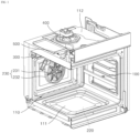
- FIG. 1 is a diagram schematically showing a cooking appliance according to an embodiment.
- FIG. 2 is a plan view showing a portion of FIG. 1 .
- FIG. 3 is a view of a ceiling plate 112 from the inside of a cavity 100 of a cooking appliance according to an embodiment.
- the cooking appliance may include the cavity 100, which is a space in which food to be cooked is accommodated.
- the food to be cooked may be placed in the cavity 100 and may be heated at a high temperature.
- the cooking appliance may have a panel 110 to define the cavity 100.
- the panel 110 may be open at a front side facing a door and may include a side plate, a bottom plate 111, and the ceiling plate 112.
- the side plate may form a side wall of the cavity 100
- the bottom plate 111 may form a bottom of the cavity 100
- the ceiling plate 112 may form a ceiling of the cavity 100.
- the heater 200 may include a broil heater 210, a bake heater 220, and a convection heater 230. Such heaters 210, 220, and 230 may be operated via, for example, an electric resistance heating scheme.
- a failure or a malfunction may occur in the relay 700.
- an electrical short may occur in an internal circuit or a wire of the relay 700. Therefore, even when the controller 600 transmits a command signal to turn off each of the heaters 210, 220, and 230 to the relay 700, the relay 700 may not be able to turn off each of the heaters 210, 220, and 230 because of the short circuit in the relay 700.
- such state may be a case in which the heater 200 continues to be turned on because of the short circuit in the relay 700 even though the controller 600 has turned off the heater 200 as the cooking mode or the self-clean mode is ended.
- Such control may be implemented using the circuit breaker 500 that may turn off the heater 200 by cutting off the power to the entire cooking appliance, preventing the electricity from being supplied to the cooking appliance, even when the command signal is not received from the controller 600.
- controller 600 may use the thermistor 300 and the blowing fan 400 to ultimately short-circuit the breaker 500 to cut off the power to the cooking appliance. This will be described in detail below.
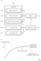
- FIG. 5 is a graph for illustrating a temperature change rate of the cavity 100 of the cooking appliance over time.
- the temperature of the cavity 100 may gradually increase over time.
- the controller 600 When the relay 700 operates normally (a normal condition), when the controller 600 terminates the operation of the heater 200, the heater 200 is turned off, so that, as shown in a graph indicated by a hidden line in FIG. 5 , the temperature of the cavity 100 may decrease over time.
- the controller 600 when the relay 700 operates abnormally (an abnormal condition), the controller 600 is in a control incapable state where it is not able to control the heater 200, and the heater 200 remains turned on even though the controller 600 has turned off the heater 200, so that, as shown in a graph indicated by a solid line, the temperature of the cavity 100 may continue to increase over time.
- the controller 600 needs to identify whether the heater 200 is actually turned off and clearly turn off the heater 200.
- the controller 600 may identify that the temperature of the cavity 100 continues to increase under the above-mentioned abnormal condition, identify that the heater 200 is still turned on, and take action to cut off the power to the entire cooking appliance by short-circuiting the circuit breaker 500.
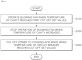
- FIG. 6 is a flowchart showing a method for controlling a cooking appliance according to an embodiment.
- the control method of the embodiment may include a blowing fan operation step (S100), a blowing fan off step (S200), and a power off step (S300).
- S100 blowing fan operation step
- S200 blowing fan off step
- S300 power off step
- the temperature of the cavity 100 may be measured by the thermistor 300.
- the blowing fan 400 may be operated when the temperature of the cavity 100 reaches a first set temperature T1.
- the blowing fan 400 may operate to discharge hot air from the cavity 100 to the outside, and relatively colder surrounding air may flow into the cavity 100, allowing the cavity 100 to be cooled.
- the first set temperature T1 may be, for example, 120°C, but the present disclosure may not be limited thereto.
- the controller 600 has already turned off the heater 200.
- the heater 200 is still turned on even though the controller 600 has turned off the heater 200, and thus the controller 600 is not able to control the heater 200, the power to the cooking appliance may be cut off according to the control method of the embodiment.
- the operation of the blowing fan 400 may be stopped when the temperature of the cavity 100 increases.
- the temperature of the cavity 100 continues to increase, this is the case in which the controller 600 is not able to control the heater 200 and the heater 200 is in the on state, so that it is necessary to cut off the power to the cooking appliance.
- the cavity 100 When the blowing fan 400 is turned off, the cavity 100 may not be cooled because surrounding air does not flow thereinto, and the temperature thereof may increase further. Accordingly, the heat from the cavity 100 may be transferred to the circuit breaker 500 outside the cavity 100, causing a temperature of the circuit breaker 500 to increase.
- the power to the cooking appliance may be cut off when the temperature of the circuit breaker 500 reaches the set temperature.
- the circuit breaker 500 may cut off the power when the temperature increases and reaches a certain temperature at which there is a risk of fire or explosion.
- the power to the cooking appliance may be cut off as the circuit breaker 500 is short-circuited when the temperature of the circuit breaker 500 reaches cut off set value Vcut.
- the cut off set value Vcut may correspond to a temperature at which there is a risk of fire or explosion in the cooking appliance, and may be set appropriately.
- the cut off set value Vcut is a temperature sensed by the circuit breaker 500 outside the cavity 100
- the cut off set value Vcut may be lower than the temperature of the cavity 100 at this time.
- the cut off set value Vcut may be set to a temperature higher than the first set temperature T1.
- the cut off set value Vcut When the cut off set value Vcut is equal to or lower than the first set temperature T1, the power to the cooking appliance is cut off before the blowing fan 400 is turned on, so that the cooking appliance does not operate at all and the control method of the embodiment is not able to proceed.
- the cut off set value Vcut may be, for example, 140°C, but the present disclosure may not be limited thereto.
- the controller 600 may cut off the power to the cooking appliance by short-circuiting the circuit breaker 500 using the controllable thermistor 300 and blowing fan 400. Accordingly, the heater 200 that is uncontrollable may be turned off.
- the cooking appliance may turn the heater 200 on/off in any situation to prevent the fire or the explosion caused by the heater 200, thereby promoting user safety.
- the control method of the embodiment may be performed during an idle mode in which the cooking appliance does not operate in the cooking mode or the self-clean mode in which the cavity 100 is heated and cleaned.
- the idle mode refers to a mode in which the controller 600 operates while the cooking appliance is turned on. Further, in the idle mode, the heater 200 is not used, so that the controller 600 is in the state of having turned off the heater 200.
- a maximum temperature of the cavity 100 is lower than a temperature of the cavity 100 for performing the control method of the embodiment.
- the maximum temperature of the cavity 100 is equal to or lower than 290°C, but a second set temperature T2, which is a standard for measuring the temperature of the cavity 100 for performing the control method of the embodiment to be described later, may be equal to or higher than 300°C. Therefore, it may be appropriate not to proceed with the control method of the embodiment in the cooking mode.
- a maximum temperature of the cavity 100 is higher than the temperature of the cavity 100 for performing the control method of the embodiment.
- the maximum temperature of the cavity 100 is equal to or higher than 400°C, but the second set temperature T2 in the control method of the embodiment may be equal to or lower than 350°C. Therefore, like in the cooking mode, it may be appropriate not to proceed with the control method of the embodiment in the self-clean mode.
- FIG. 7 is a flowchart showing sub-steps of the blowing fan off step (S200) according to an embodiment.
- the blowing fan off step (S200) may include a first temperature measurement step (S210), a second temperature measurement step (S220), a temperature difference calculation step (S230), and a blowing fan stop step (S240).
- the first temperature measurement step (S210) when the temperature of the cavity 100 reaches the second set temperature T2, the thermistor 300 may measure the temperatures of the cavity 100 at a set time interval. The thermistor 300 may measure the temperature of the cavity 100, and when the temperature reaches the second set temperature T2, the first temperature measurement step (S210) may be performed.
- the second set temperature T2 may be appropriately set in consideration of the temperature at which there is the risk of fire or explosion because of overheating of the heater 200 when the cooking appliance is in the idle mode.
- the second set temperature T2 may be 320°C, but the present disclosure may not be limited thereto.
- the set time interval may be set to a relatively short time, for example, 6 seconds, but the present disclosure may not be limited thereto.
- a plurality of first temperatures may be measured at the set time interval.
- the second set temperature T2 may be set higher than the maximum temperature of the cavity 100 in the cooking mode and lower than the maximum temperature of the cavity 100 in the self-clean mode. Therefore, it may be appropriate that the control method of the embodiment does not proceed in the cooking mode and the self-clean mode.
- the thermistor 300 may measure the temperature of the cavity 100 after a set time to be elapsed elapses.
- a second temperature measured in the second temperature measurement step (S220) may be a means of determining whether the temperature of cavity 100 is increasing or decreasing.
- the temperature of the cavity 100 may frequently increase or decrease in a short time period because of disturbance, uneven heating, and the like. Therefore, to clearly identify a temperature change trend, the time to be elapsed may be set to be relatively long compared to the time interval for measuring the first temperature in the first temperature measurement step (S210). For example, the set time to be elapsed may be set to 90 seconds, but the present disclosure may not be limited thereto.
- the controller 600 may calculate a difference value between the first temperature and the second temperature.
- the difference value between the first temperature and the second temperature means a value of second temperature-first temperature.
- the controller 600 may receive the information on the temperature of the cavity 100 from the thermistor 300, recall the first temperature measured in advance, and calculate the difference value by subtracting the first temperature from the re-measured second temperature
- the operation of the blowing fan 400 may be stopped when the number of times the difference value between the first temperature and the second temperature is equal to or greater than a reference value Vref which is pre-determined is equal to or greater than a set number of times.
- a reference value Vref which is pre-determined is equal to or greater than a set number of times.
- the reference value Vref may be appropriately set to a value at which it may be determined that the temperature is continuously increasing.
- the reference value Vref may be 8°C, but the present disclosure may not be limited thereto.
- the set number of times may be appropriately set to a value at which the temperature change trend may be identified.
- the set number of times may be three times, but the present disclosure may not be limited thereto.
- the cooking appliance is in the idle mode, so that the controller 600 is in the state of having turned off the heater 200. Because the temperature of the cavity 100 is continuously increasing nevertheless, this may be the situation in which the heater 200 is in the on state and is not able to be controlled by the controller 600.
- the controller 600 may turn off the blowing fan 400 to induce the temperature of the circuit breaker 500 to increase. Thereafter, as described above, the circuit breaker 500 may be short-circuited, the power to the cooking appliance may be cut off, and the heater 200 may be completely turned off.
- the controller 600 may measure the plurality of first temperatures and a plurality of second temperatures at time intervals and calculate the respective difference values therebetween to clearly identify whether the heater 200 is still in the on state even though the heater 200 has turned off the same, thereby clearly identifying whether the heater 200 is operating abnormally.
- FIG. 8 is a diagram for illustrating a case in which the blowing fan 400 is turned off in a method for controlling a cooking appliance according to an embodiment.
- the thermistor 300 may measure the first temperatures, which are the temperature of the cavity 100, a set number of times, for example, three times at a set time interval, for example, 6 seconds (the first temperature measurement step (S210)).
- the measured first temperatures are indicated as T11, T12, and T13, respectively, as shown in FIG. 8 and FIG. 9 to be described later.
- the thermistor 300 may measure the second temperatures, which are the temperatures of the cavity 100, a set number of times at a set time interval (the second temperature measurement step (S220)).
- the measured second temperatures are indicated as T21, T22, and T23, respectively, as shown in FIGS. 8 and 9 .
- the number of times the first temperatures are measured and the number of times the second temperatures are measured may be equal to each other. Therefore, when the first temperatures are measured three times in the first temperature measurement step (S210), the second temperatures may be measured three times in the second temperature measurement step (S220).
- the thermistor 300 may measure the temperatures of the cavity 100 at the time interval equal to the set time interval in the first temperature measurement step (S210). Therefore, when the first temperatures are measured at the time interval of 6 seconds in the first temperature measurement step (S210), the second temperatures may be measured at the time interval of 6 seconds also in the second temperature measurement step (S220).
- times to be elapsed between respective pairs of the first temperature measurement time points and the second temperature measurement time points may be equal to each other. Therefore, times to be elapsed, that is, set times to be elapsed, between respective pairs of T11-T21, T12-T22, and T12-T23, may be equal to each other to be, for example, 90 seconds.
- the set time interval for measuring the temperatures and the number of times the temperatures are measured may be uniform for the plurality of first temperatures and for the plurality of second temperatures. Additionally, the set times to be elapsed between respective pairs of the plurality of first temperatures and the plurality of second temperatures may be equal to each other.
- the difference value between the first temperature and the second temperature may be clearly identified, and thus the temperature change trend inside the cavity 100 may be clearly identified.
- the number of times the thermistor 300 measures the temperatures of the cavity 100 in each of the first temperature measurement step (S210) and the second temperature measurement step (S220) may be equal to the set number of times in the blowing fan stop step (S240).
- the set number of times in the blowing fan stop step (S240) is, for example, three times
- the first temperatures may also be measured three times and the second temperatures may also be measured three times.
- the difference value between the first temperature and the second temperature is calculated and examined the set number of times. Therefore, it is appropriate that each of the first temperatures and the second temperatures required for the determination are also measured the set number of times in the blowing fan stop step (S240). Further, there is no need to measure each of the first temperatures and the second temperatures more, and each of the first temperatures and the second temperatures should not be measured less.
- the first temperatures and the second temperatures measured in the cavity 100 may be transmitted to the controller 600, and the controller 600 may calculate the respective difference values between the first temperatures and the second temperatures and compare the difference values with the reference value Vref.
- the difference value between the first temperature and the second temperature may be calculated as second temperature-first temperature.
- the reference value Vref may be, for example, 8°C as described above.
- the controller 600 may turn off the blowing fan 400. This is the case in which the temperature of the cavity 100 continues to increase, and is highly likely to be the case in which, although the controller 600 has directly turned off the heater 200, the heater 200 continues to operate in the on state caused by the failure, the malfunction, or the like, so that the controller 600 may turn off the blowing fan 400 to allow the circuit breaker 500 to be short-circuited because of the high temperature.
- the cavity 100 may not be cooled by the blowing fan 400, and the temperature of the cavity 100 may increase more quickly, so that the temperature of the circuit breaker 500 may also increase by the heat conducted from the cavity 100.
- the circuit breaker 500 may operate and be short-circuited to cut off the power to the cooking appliance. As the power to the cooking appliance is cut off, the electricity may not be supplied to the heater 200, and accordingly, the heater 200 may also be turned off.
- the circuit breaker 500 may be constructed so as not to be operated by the controller 600. Because the controller 600 is in the control incapable state where it is not able to control the heater 200 in the first place, the circuit breaker 500 may reliably turn off the heater 200 by cutting off the power to the cooking appliance in response to the temperature increase rather than the command from the controller 600.
- FIG. 9 is a diagram for illustrating a case in which the blowing fan 400 remains turned on in a method for controlling a cooking appliance according to an embodiment.
- FIG. 9 shows an embodiment in which remaining values and other conditions are the same as those in the case shown in FIG. 8 except for the measurement result of the second temperatures.
- the reference value Vref may be, for example, 8°C as described above.
- the embodiment shown in FIG. 9 is a case in which the number of times the difference value between the first temperature and the second temperature is equal to or greater than the reference value Vref is smaller than the set number of times. In other words, the respective three difference values between the first temperatures and the second temperatures are not all equal to or greater than the reference value Vref.
- the blowing fan 400 may remain turned on. In this case, judging from the temperature change of the cavity 100, it may be seen that heater 200 is turned off or at least is not in the uncontrollable state at the time of measuring the second temperature, so that the blowing fan 400 may be continuously operated to cool the cavity 100.
- control method of the embodiment may proceed with the first temperature measurement step (S210) again. That is, the controller 600 may initialize the blowing fan off step (S200) described above and proceed with the first temperature measurement step (S210) of the cavity 100 again.
- the heater 200 When the heater 200 is turned off, the temperature of the cavity 100 will continue to decrease, so that the first temperature will not be measured again. However, when the temperature of the cavity 100 reaches the second set temperature T2 again, the first temperature measurement step (S210) and the following steps will be performed again.
- FIG. 10 is a flowchart for illustrating an entire process of a method for controlling a cooking appliance according to an embodiment.
- the method for controlling the cooking appliance according to an embodiment will be described overall with reference to FIG. 10 .
- the power may be applied to the cooking appliance, and the cooking appliance may proceed to the cooking mode or the self-clean mode.
- the cooking appliance In the cooking mode or the self-clean mode, the cooking appliance may be controlled by the controller 600 and may operate in the corresponding mode.
- the control method of the embodiment may be performed in the idle mode as described above.
- the blowing fan 400 may operate to cool the cavity 100.
- the thermistor 300 may measure the temperatures of the cavity 100 at the set time interval, and measure the plurality of first and second temperatures described above.
- the controller 600 may receive information on the first temperature and the second temperature from the thermistor 300, calculate the respective difference values between the first temperatures and the second temperatures, and compare such values with the reference value Vref.
- the controller 600 may turn off the blowing fan 400.
- the temperature of the circuit breaker 500 may increase.
- the circuit breaker 500 may be short-circuited when the temperature thereof reaches the cut off set value Vcut. Accordingly, the power to the cooking appliance may be completely cut off, and at this time, the controller 600 may also be turned off.
- the heater 200 When the power to the cooking appliance is cut off, the heater 200 does not receive the electricity, so that the heater 200 may be turned off for sure.
- Such control method may effectively prevent the fire and the explosion of the cooking appliances by turning off the heater 200 in the uncontrollable state.
Landscapes
- Engineering & Computer Science (AREA)
- Chemical & Material Sciences (AREA)
- Combustion & Propulsion (AREA)
- Mechanical Engineering (AREA)
- General Engineering & Computer Science (AREA)
- Chemical Kinetics & Catalysis (AREA)
- Electric Stoves And Ranges (AREA)
Abstract
Description
- The present disclosure relates to a method for controlling a cooking appliance, and more particularly, to a method for controlling a cooking appliance having a structure that cuts off power to the cooking appliance when a fire or explosion may occur caused by overheating of a heater.
- A cooking appliance, one of home appliances, has a cavity that accommodates food to be cooked therein. The cavity is defined as a space by panels.
- The cooking appliance is equipped with the cavity and a heater to heat the food. There may be a plurality of heaters, and each heater may heat air and the food in the cavity via conduction, convection, or radiation.
- In the cooking appliance, the heater may operate in a cooking mode to heat and cook the food, thereby heating the cavity. Additionally, the heater may operate in a self-clean mode.
- The self-clean mode is a function of the cooking appliance that removes organic matter attached to the panel on its own. In the self-clean mode, the heater may operate to heat the inside of the cavity at a higher temperature than in the cooking mode, thereby removing the organic matter attached to the panel of the cavity via thermal decomposition at the high temperature.
- Because the heater generates high temperature, on/off operations need to be accurately controlled by a controller equipped in the cooking appliance. However, an abnormality may occur in the cooking appliance because of a failure of a component or the like.
- For example, even though the controller transmits a signal commanding the heater to be turned off after the cooking mode or the self-clean mode ends, the heater may continue to operate without being turned off because of the failure, a malfunction, or the like of the component of the cooking appliance.
- When the heater continues to operate despite the turn-off command of the controller, a fire or explosion may be caused. Therefore, there is a need for a cooking appliance that has a structure that may turn off the heated heater regardless of the command from the controller even in a situation in which the controller is not able to control the heater.
- The present disclosure is to provide a method for controlling a cooking appliance with a structure that may prevent overheating of a heater.
- Additionally, the present disclosure is to provide a method for controlling a cooking appliance with a structure that may turn off a heater even when the heater is in an uncontrollable state.
- Additionally, the present disclosure is to provide a method for controlling a cooking appliance with a structure that may allow a controller to sense whether a heater is operating abnormally.
- Purposes according to the present disclosure are not limited to the above-mentioned purpose. Other purposes and advantages according to the present disclosure that are not mentioned may be understood based on following descriptions, and may be more clearly understood based on embodiments according to the present disclosure. Further, it will be easily understood that the purposes and advantages according to the present disclosure may be realized using means shown in the claims or combinations thereof.
- The present invention is defined by the independent claims; the dependent claims describe embodiments of the present invention.
- An embodiment of a method for controlling a cooking appliance includes a blowing fan operation step of operating a blowing fan when a temperature of a cavity reaches a first set temperature, a blowing fan off step of stopping the operation of the blowing fan when the temperature of the cavity increases, and a power off step of cutting off power to the cooking appliance when a temperature of a circuit breaker reaches a cut off set value.
- The circuit breaker may operate and cut off the power to the cooking appliance when the temperature of the circuit breaker reaches the cut off set value, and may not be operated by a controller. The heater in a state of not being able to be controlled by the controller may be turned off by cutting off the power to the cooking appliance using the circuit breaker, thereby preventing fire or explosion of the cooking appliance resulted from overheating of the heater.
- The cooking appliance may include a thermistor that is disposed in the cavity and measures a temperature of the cavity, the blowing fan that is disposed outside the cavity and discharges air from the cavity to the surroundings, and the circuit breaker that is disposed outside the cavity and cuts off power to the cooking appliance.
- When the heater is uncontrollable and turned on, the controller may use the controllable thermistor and blowing fan to short-circuit the circuit breaker, thereby cutting off the power to the cooking appliance.
- The blowing fan off step may include a first temperature measurement step of measuring, by the thermistor, first temperatures of the cavity at a set time interval when the temperature of the cavity reaches a second set temperature, and a second temperature measurement step of measuring, by the thermistor, second temperatures of the cavity, wherein each second temperature is measured at a time after a set time to be elapsed from a time when each first temperature was measured.
- Further, the blowing fan off step may include a temperature difference calculation step of calculating respective difference values between the first temperatures and the second temperatures.
- The controller may measure each of the plurality of first temperatures and each of the plurality of second temperatures with a time interval therebetween and calculate a difference value therebetween, thereby clearly identifying whether the heater is still turned on even when the heater is to be turned off.
- The blowing fan off step may include a blowing fan stop step of stopping the operation of the blowing fan when the number of times the difference value between the first temperature and the second temperature is equal to or greater than a reference value which is pre-determined is equal to or greater than a set number of times.
- The method may be performed during an idle mode when the cooking appliance does not operate in a cooking mode or in a self-clean mode of heating and cleaning the cavity. Therefore, the cooking appliance may turn off the heater under any circumstances.
- In the method for controlling the cooking appliance according to the present disclosure, when the fire or the explosion may occur because of the overheating of the heater, safety of the user may be ensured by turning off the heater by cutting off the power to the cooking appliance.
- Additionally, in the method for controlling the cooking appliance according to the present disclosure, when the heater is uncontrollable and is turned on, the controller may use the controllable thermistor and blowing fan to short-circuit the circuit breaker, thereby cutting off the power to the cooking appliance. Accordingly, the uncontrollable heater may be turned off.
- As a result, the cooking appliance may prevent the fire or the explosion caused by the heater by turning off the heater under any circumstances, thereby ensuring the safety of the user.
- In addition, in the method for controlling the cooking appliance according to the present disclosure, the controller may measure each of the plurality of first temperatures and each of the plurality of second temperatures with the time interval therebetween and calculate the difference value therebetween, thereby clearly identifying whether the heater is still turned on even when the heater is turned off and thus clearly identifying whether the heater is operating abnormally.
- In addition to the above-mentioned effects, specific effects of the present disclosure will be described below while describing the specific details for carrying out the invention.
-
-
FIG. 1 is a diagram schematically showing a cooking appliance according to an embodiment. -
FIG. 2 is a plan view showing a portion ofFIG. 1 . -
FIG. 3 is a view of a ceiling plate from the inside of a cavity of a cooking appliance according to an embodiment. -
FIG. 4 is a schematic diagram for illustrating a control structure of a cooking appliance. -
FIG. 5 is a graph for illustrating a temperature change rate of a cavity of a cooking appliance over time. -
FIG. 6 is a flowchart showing a method for controlling a cooking appliance according to an embodiment. -
FIG. 7 is a flowchart showing sub-steps of a blowing fan off step according to an embodiment. -
FIG. 8 is a diagram for illustrating a case in which a blowing fan is turned off in a method for controlling a cooking appliance according to an embodiment. -
FIG. 9 is a diagram for illustrating a case in which a blowing fan remains turned on in a method for controlling a cooking appliance according to an embodiment. -
FIG. 10 is a flowchart for illustrating an entire process of a method for controlling a cooking appliance according to an embodiment. - The above-mentioned purposes, features, and advantages will be described in detail later with reference to the attached drawings, so that those skilled in the art in the technical field to which the present disclosure belongs may easily practice the technical ideas of the present disclosure. In describing the present disclosure, when it is determined that a detailed description of the publicly known technology related to the present disclosure may unnecessarily obscure the gist of the present disclosure, the detailed description thereof will be omitted. Hereinafter, a preferred embodiment according to the present disclosure will be described in detail with reference to the attached drawings. In the drawings, identical reference numerals are used to indicate identical or similar components.
- It will be understood that, although the terms "first", "second", "third", and so on may be used herein to describe various elements, components, regions, layers and/or sections, these elements, components, regions, layers and/or sections should not be limited by these terms. These terms are used to distinguish one element, component, region, layer or section from another element, component, region, layer or section. Thus, a first element, component, region, layer or section described under could be termed a second element, component, region, layer or section, without departing from the scope of the present disclosure.
- As used herein, the singular constitutes "a" and "an" are intended to include the plural constitutes as well, unless the context clearly indicates otherwise.
- It will be further understood that the terms "comprise", "comprising", "include", and "including" when used in this specification, specify the presence of the stated features, integers, operations, elements, and/or components, but do not preclude the presence or addition of one or more other features, integers, operations, elements, components, and/or portions thereof.
- Throughout the present disclosure, "A and/or B" means A, B, or A and B, unless otherwise specified, and "C to D" means C inclusive to D inclusive unless otherwise specified.
- Throughout the present document, "up, down, front, rear" refers to a location of a cooking appliance when the cooking appliance is installed for daily use. Additionally, throughout the present document, a "vertical direction" refers to a vertical direction of the cooking appliance when the cooking appliance is installed for daily use. A "left and right direction" refers to a direction perpendicular to the vertical direction, and a front and rear direction refers to a direction perpendicular to both the vertical direction and the left and right direction. A "lateral direction" may have the same meaning as the left and right direction, and these terms may be used interchangeably herein.
-
FIG. 1 is a diagram schematically showing a cooking appliance according to an embodiment.FIG. 2 is a plan view showing a portion ofFIG. 1 .FIG. 3 is a view of aceiling plate 112 from the inside of acavity 100 of a cooking appliance according to an embodiment. - The cooking appliance may include the
cavity 100, which is a space in which food to be cooked is accommodated. The food to be cooked may be placed in thecavity 100 and may be heated at a high temperature. - The cooking appliance may have a
panel 110 to define thecavity 100. Thepanel 110 may be open at a front side facing a door and may include a side plate, abottom plate 111, and theceiling plate 112. The side plate may form a side wall of thecavity 100, thebottom plate 111 may form a bottom of thecavity 100, and theceiling plate 112 may form a ceiling of thecavity 100. - The food placed in the
cavity 100 may be heated in a high-temperature environment. To this end, the cooking appliance may be equipped with aheater 200 to heat thecavity 100. Theheater 200 may be disposed incavity 100. - The
heater 200 may include abroil heater 210, abake heater 220, and aconvection heater 230.Such heaters - The
broil heater 210 may apply radiant heat to thecavity 100. For example, thebroil heater 210 may be disposed at an upper portion of thecavity 100, that is, at a location adjacent to theceiling plate 112 of thepanel 110, and may be equipped as a heating tube and heated to heat air in thecavity 100 by applying the radiant heat to thecavity 100. - As shown in
FIG. 3 , thebroil heater 210 may include aninner heater 211 and anouter heater 212. Theinner heater 211 may be disposed at the upper portion of thecavity 100. - The
outer heater 212 may be disposed at the upper portion of thecavity 100 to surround theinner heater 211, and may have a lower output than theinner heater 211. Theouter heater 212 may be disposed in a wider range in thecavity 100 than theinner heater 211. - Therefore, the
outer heater 212 may apply the radiant heat to a wider area of thecavity 100 compared to theinner heater 211, so that theouter heater 212 may produce the same temperature increase effect in thecavity 100 as theinner heater 211 with an output smaller than that of theinner heater 211. - The
bake heater 220 may heat thepanel 110 constituting thecavity 100. For example, thebake heater 220 may be disposed under thebottom plate 111 of thepanel 110 and disposed outside thecavity 100. Thebake heater 220 may be equipped as a plate-shaped heating element or a heating tube and apply the radiant heat to thebottom plate 111. - The heat from the
bottom plate 111 heated by thebake heater 220 may be transferred to an entirety of thepanel 110 via conduction. Thepanel 110 heated as such may apply the radiant heat to thecavity 100. Therefore, thebake heater 220 may heat air in thecavity 100 by transferring the heat sequentially via radiation, conduction, and radiation. - The
convection heater 230 may be disposed at a rear portion of thecavity 100 to extend through thepanel 110, and may include a convection fan 231 and a convection heating unit 232. The convection heating unit 232 may be equipped as a heating tube and be heated. The convection fan 231 may be disposed in front of the convection heating unit 232 and operate to circulate air inside thecavity 100. Accordingly, the heat of the convection heating unit 232 may heat air in thecavity 100 via convection. - In the cooking appliance, the
heater 200 may heat thecavity 100 by operating in a cooking mode of heating and cooking the food. Additionally, theheater 200 may operate in a self-clean mode. - The self-clean mode is a function of the cooking appliance that removes organic matter attached to the
panel 110 on its own. In the self-clean mode, theheater 200 may operate to heat the inside of the cavity at a higher temperature than in the cooking mode, thereby removing the organic matter attached to thepanel 110 of thecavity 100 via thermal decomposition at a high temperature. - Because the
heater 200 generates high temperature, on/off operations need to be accurately controlled by acontroller 600 equipped in the cooking appliance. However, an abnormality may occur in the cooking appliance because of a failure of a component or the like. - For example, even though the
controller 600 transmits a signal commanding theheater 200 to be turned off after the cooking mode or the self-clean mode ends, theheater 200 may continue to operate without being turned off because of the failure, a malfunction, or the like of the component of the cooking appliance. - When the
heater 200 continues to operate despite the turn-off command of thecontroller 600, a fire or explosion may be caused. Therefore, there is a need for a cooking appliance that has a structure that may turn off theheated heater 200 regardless of the command from thecontroller 600 even in a situation in which thecontroller 600 is not able to control theheater 200. - Hereinafter, to solve the above-mentioned problems, components included in the cooking appliance will first be described, and then a method for controlling the cooking appliance according to an embodiment will be described in detail.
- The cooking appliance may include a
thermistor 300, a blowingfan 400, acircuit breaker 500, and thecontroller 600. Thethermistor 300 may be disposed in thecavity 100 and may measure a temperature of thecavity 100. Thethermistor 300 may be electrically connected to thecontroller 600, and information on the temperature of thecavity 100 measured by thethermistor 300 may be transmitted to thecontroller 600. - The blowing
fan 400 may be disposed outside of thecavity 100 and may discharge air from thecavity 100 to the surroundings. For example, the blowingfan 400 may be disposed on theceiling plate 112 of thepanel 110. The blowingfan 400 and thecavity 100 may be connected to each other via piping. - In one example, the
panel 110 constituting thecavity 100 may have a plurality of holes through which external air may flow into thecavity 100. - When the blowing
fan 400 operates, air inside thecavity 100 may be discharged to the outside of thecavity 100, and surrounding air may flow into thecavity 100 via the holes defined in thepanel 110. Accordingly, hot air inside thecavity 100 may be discharged to the outside, and relatively colder surrounding air may flow into thecavity 100. In this way, thecavity 100, which was at the high temperature, may be cooled. - The
circuit breaker 500 may be disposed outside thecavity 100 and may cut off power to the cooking appliance. For example, thecircuit breaker 500 may be disposed on theceiling plate 112 of thepanel 110. Thecircuit breaker 500 may not be controlled in operation by thecontroller 600, but may operate by sensing heat transferred from thecavity 100 to thecircuit breaker 500 via conduction of the heat from theceiling plate 112. - In other words, the
circuit breaker 500 may sense the heat and cut off the power to the cooking appliance when a cut off set value is reached. Thecircuit breaker 500 may be electrically connected to an external source that supplies electricity to the cooking appliance. Therefore, when reaching the cut off set value, thecircuit breaker 500 may be electrically short-circuited to cut off electrical connection between the external source and the cooking appliance, thereby cutting off the power to the cooking appliance. - The
circuit breaker 500 may be equipped, for example, as a thermal cut out (TCO) device. For example, thecircuit breaker 500 may have a bi-metal structure in which metals with different thermal deformation rates are joined together. However, thecircuit breaker 500 may be constructed in other ways without being limited thereto. - The
controller 600 may be equipped in the cooking appliance and may control an operation of the cooking appliance. For example, thecontroller 600 may be equipped as software on a circuit board of the cooking appliance and may be connected to a storage device to assist the operation of thecontroller 600. -
FIG. 4 is a schematic diagram for illustrating a control structure of a cooking appliance. Thecontroller 600 may be electrically connected to thethermistor 300 and the blowingfan 400 to control the operation of the blowingfan 400 and receive information on the temperature of thecavity 100 from thethermistor 300. - The cooking appliance may include a
relay 700. Therelay 700 may be electrically connected to thecontroller 600 and theheater 200, and may turn on or off all or some of thebroil heater 210, thebake heater 220, and theconvection heater 230 by receiving a command signal from thecontroller 600. - A failure or a malfunction may occur in the
relay 700. For example, an electrical short may occur in an internal circuit or a wire of therelay 700. Therefore, even when thecontroller 600 transmits a command signal to turn off each of theheaters relay 700, therelay 700 may not be able to turn off each of theheaters relay 700. - In this case, the
controller 600 may be unable to control the operation of theheater 200, and theheater 200 may remain turned on even though thecontroller 600 has turned off theheater 200. - For example, such state may be a case in which the
heater 200 continues to be turned on because of the short circuit in therelay 700 even though thecontroller 600 has turned off theheater 200 as the cooking mode or the self-clean mode is ended. - When the
heater 200 remains turned on despite thecontroller 600 has turned off the same, it is very dangerous as there is a risk of fire. Therefore, a control method to turn off theheater 200 even when therelay 700 malfunctions because of the short circuit or the like is needed. - Such control may be implemented using the
circuit breaker 500 that may turn off theheater 200 by cutting off the power to the entire cooking appliance, preventing the electricity from being supplied to the cooking appliance, even when the command signal is not received from thecontroller 600. - Even when the
relay 700 malfunctions, thethermistor 300 and the blowingfan 400 operate normally, so thatcontroller 600 may use thethermistor 300 and the blowingfan 400 to ultimately short-circuit thebreaker 500 to cut off the power to the cooking appliance. This will be described in detail below. -
FIG. 5 is a graph for illustrating a temperature change rate of thecavity 100 of the cooking appliance over time. When theheater 200 operates, the temperature of thecavity 100 may gradually increase over time. - When the
relay 700 operates normally (a normal condition), when thecontroller 600 terminates the operation of theheater 200, theheater 200 is turned off, so that, as shown in a graph indicated by a hidden line inFIG. 5 , the temperature of thecavity 100 may decrease over time. - However, when the
relay 700 operates abnormally (an abnormal condition), thecontroller 600 is in a control incapable state where it is not able to control theheater 200, and theheater 200 remains turned on even though thecontroller 600 has turned off theheater 200, so that, as shown in a graph indicated by a solid line, the temperature of thecavity 100 may continue to increase over time. - In such abnormal condition, the
controller 600 needs to identify whether theheater 200 is actually turned off and clearly turn off theheater 200. - In the embodiment, the
controller 600 may identify that the temperature of thecavity 100 continues to increase under the above-mentioned abnormal condition, identify that theheater 200 is still turned on, and take action to cut off the power to the entire cooking appliance by short-circuiting thecircuit breaker 500. -
FIG. 6 is a flowchart showing a method for controlling a cooking appliance according to an embodiment. The control method of the embodiment may include a blowing fan operation step (S100), a blowing fan off step (S200), and a power off step (S300). At each step, the temperature of thecavity 100 may be measured by thethermistor 300. - In the blowing fan operation step (S100), the blowing
fan 400 may be operated when the temperature of thecavity 100 reaches a first set temperature T1. The blowingfan 400 may operate to discharge hot air from thecavity 100 to the outside, and relatively colder surrounding air may flow into thecavity 100, allowing thecavity 100 to be cooled. In this regard, the first set temperature T1 may be, for example, 120°C, but the present disclosure may not be limited thereto. - In this regard, the
controller 600 has already turned off theheater 200. When theheater 200 is still turned on even though thecontroller 600 has turned off theheater 200, and thus thecontroller 600 is not able to control theheater 200, the power to the cooking appliance may be cut off according to the control method of the embodiment. - In the blowing fan off step (S200), the operation of the blowing
fan 400 may be stopped when the temperature of thecavity 100 increases. When the temperature of thecavity 100 continues to increase, this is the case in which thecontroller 600 is not able to control theheater 200 and theheater 200 is in the on state, so that it is necessary to cut off the power to the cooking appliance. - When the blowing
fan 400 is turned off, thecavity 100 may not be cooled because surrounding air does not flow thereinto, and the temperature thereof may increase further. Accordingly, the heat from thecavity 100 may be transferred to thecircuit breaker 500 outside thecavity 100, causing a temperature of thecircuit breaker 500 to increase. - In the power off step (S300), the power to the cooking appliance may be cut off when the temperature of the
circuit breaker 500 reaches the set temperature. Thecircuit breaker 500 may cut off the power when the temperature increases and reaches a certain temperature at which there is a risk of fire or explosion. - In the power off step (S300), the power to the cooking appliance may be cut off as the
circuit breaker 500 is short-circuited when the temperature of thecircuit breaker 500 reaches cut off set value Vcut. The cut off set value Vcut may correspond to a temperature at which there is a risk of fire or explosion in the cooking appliance, and may be set appropriately. - However, because the cut off set value Vcut is a temperature sensed by the
circuit breaker 500 outside thecavity 100, the cut off set value Vcut may be lower than the temperature of thecavity 100 at this time. Additionally, the cut off set value Vcut may be set to a temperature higher than the first set temperature T1. - When the cut off set value Vcut is equal to or lower than the first set temperature T1, the power to the cooking appliance is cut off before the blowing
fan 400 is turned on, so that the cooking appliance does not operate at all and the control method of the embodiment is not able to proceed. The cut off set value Vcut may be, for example, 140°C, but the present disclosure may not be limited thereto. - In the embodiment, when the
heater 200 is uncontrollable and turned on, thecontroller 600 may cut off the power to the cooking appliance by short-circuiting thecircuit breaker 500 using thecontrollable thermistor 300 and blowingfan 400. Accordingly, theheater 200 that is uncontrollable may be turned off. - As a result, the cooking appliance may turn the
heater 200 on/off in any situation to prevent the fire or the explosion caused by theheater 200, thereby promoting user safety. - The control method of the embodiment may be performed during an idle mode in which the cooking appliance does not operate in the cooking mode or the self-clean mode in which the
cavity 100 is heated and cleaned. - The idle mode refers to a mode in which the
controller 600 operates while the cooking appliance is turned on. Further, in the idle mode, theheater 200 is not used, so that thecontroller 600 is in the state of having turned off theheater 200. - In the cooking mode, a maximum temperature of the
cavity 100 is lower than a temperature of thecavity 100 for performing the control method of the embodiment. For example, in the cooking mode, the maximum temperature of thecavity 100 is equal to or lower than 290°C, but a second set temperature T2, which is a standard for measuring the temperature of thecavity 100 for performing the control method of the embodiment to be described later, may be equal to or higher than 300°C. Therefore, it may be appropriate not to proceed with the control method of the embodiment in the cooking mode. - In the self-clean mode, a maximum temperature of the
cavity 100 is higher than the temperature of thecavity 100 for performing the control method of the embodiment. For example, in the self-clean mode, the maximum temperature of thecavity 100 is equal to or higher than 400°C, but the second set temperature T2 in the control method of the embodiment may be equal to or lower than 350°C. Therefore, like in the cooking mode, it may be appropriate not to proceed with the control method of the embodiment in the self-clean mode. -
FIG. 7 is a flowchart showing sub-steps of the blowing fan off step (S200) according to an embodiment. - The blowing fan off step (S200) may include a first temperature measurement step (S210), a second temperature measurement step (S220), a temperature difference calculation step (S230), and a blowing fan stop step (S240).
In the first temperature measurement step (S210), when the temperature of thecavity 100 reaches the second set temperature T2, thethermistor 300 may measure the temperatures of thecavity 100 at a set time interval. Thethermistor 300 may measure the temperature of thecavity 100, and when the temperature reaches the second set temperature T2, the first temperature measurement step (S210) may be performed. - The second set temperature T2 may be appropriately set in consideration of the temperature at which there is the risk of fire or explosion because of overheating of the
heater 200 when the cooking appliance is in the idle mode. For example, the second set temperature T2 may be 320°C, but the present disclosure may not be limited thereto. - The set time interval may be set to a relatively short time, for example, 6 seconds, but the present disclosure may not be limited thereto. In the first temperature measurement step (S210), a plurality of first temperatures may be measured at the set time interval.
- As described above, the second set temperature T2 may be set higher than the maximum temperature of the
cavity 100 in the cooking mode and lower than the maximum temperature of thecavity 100 in the self-clean mode. Therefore, it may be appropriate that the control method of the embodiment does not proceed in the cooking mode and the self-clean mode. - In the second temperature measurement step (S220), the
thermistor 300 may measure the temperature of thecavity 100 after a set time to be elapsed elapses. A second temperature measured in the second temperature measurement step (S220) may be a means of determining whether the temperature ofcavity 100 is increasing or decreasing. - The temperature of the
cavity 100 may frequently increase or decrease in a short time period because of disturbance, uneven heating, and the like. Therefore, to clearly identify a temperature change trend, the time to be elapsed may be set to be relatively long compared to the time interval for measuring the first temperature in the first temperature measurement step (S210). For example, the set time to be elapsed may be set to 90 seconds, but the present disclosure may not be limited thereto. - In the temperature difference calculation step (S230), the
controller 600 may calculate a difference value between the first temperature and the second temperature. The difference value between the first temperature and the second temperature means a value of second temperature-first temperature. - The
controller 600 may receive the information on the temperature of thecavity 100 from thethermistor 300, recall the first temperature measured in advance, and calculate the difference value by subtracting the first temperature from the re-measured second temperature - In the blowing fan stop step S240, the operation of the blowing
fan 400 may be stopped when the number of times the difference value between the first temperature and the second temperature is equal to or greater than a reference value Vref which is pre-determined is equal to or greater than a set number of times. When the number of times such difference value is equal to or greater than the reference value Vref is equal to or greater than the set number of times, it may clearly be determined that the temperature of thecavity 100 is continuously increasing. - The reference value Vref may be appropriately set to a value at which it may be determined that the temperature is continuously increasing. For example, the reference value Vref may be 8°C, but the present disclosure may not be limited thereto.
- Additionally, the set number of times may be appropriately set to a value at which the temperature change trend may be identified. For example, the set number of times may be three times, but the present disclosure may not be limited thereto.
- The cooking appliance is in the idle mode, so that the
controller 600 is in the state of having turned off theheater 200. Because the temperature of thecavity 100 is continuously increasing nevertheless, this may be the situation in which theheater 200 is in the on state and is not able to be controlled by thecontroller 600. - Therefore, in this case, the
controller 600 may turn off the blowingfan 400 to induce the temperature of thecircuit breaker 500 to increase. Thereafter, as described above, thecircuit breaker 500 may be short-circuited, the power to the cooking appliance may be cut off, and theheater 200 may be completely turned off. - In the embodiment, the
controller 600 may measure the plurality of first temperatures and a plurality of second temperatures at time intervals and calculate the respective difference values therebetween to clearly identify whether theheater 200 is still in the on state even though theheater 200 has turned off the same, thereby clearly identifying whether theheater 200 is operating abnormally. -
FIG. 8 is a diagram for illustrating a case in which the blowingfan 400 is turned off in a method for controlling a cooking appliance according to an embodiment. - When the temperature of the
cavity 100 reaches the second set temperature T2, for example, 320°C, thethermistor 300 may measure the first temperatures, which are the temperature of thecavity 100, a set number of times, for example, three times at a set time interval, for example, 6 seconds (the first temperature measurement step (S210)). In this regard, the measured first temperatures are indicated as T11, T12, and T13, respectively, as shown inFIG. 8 and FIG. 9 to be described later. - Next, when a set time to be elapsed, for example, 90 seconds, elapses, the
thermistor 300 may measure the second temperatures, which are the temperatures of thecavity 100, a set number of times at a set time interval (the second temperature measurement step (S220)). In this regard, the measured second temperatures are indicated as T21, T22, and T23, respectively, as shown inFIGS. 8 and 9 . - The number of times the first temperatures are measured and the number of times the second temperatures are measured may be equal to each other. Therefore, when the first temperatures are measured three times in the first temperature measurement step (S210), the second temperatures may be measured three times in the second temperature measurement step (S220).
- Additionally, in the second temperature measurement step (S220), the
thermistor 300 may measure the temperatures of thecavity 100 at the time interval equal to the set time interval in the first temperature measurement step (S210). Therefore, when the first temperatures are measured at the time interval of 6 seconds in the first temperature measurement step (S210), the second temperatures may be measured at the time interval of 6 seconds also in the second temperature measurement step (S220). - Additionally, times to be elapsed between respective pairs of the first temperature measurement time points and the second temperature measurement time points may be equal to each other. Therefore, times to be elapsed, that is, set times to be elapsed, between respective pairs of T11-T21, T12-T22, and T12-T23, may be equal to each other to be, for example, 90 seconds.
- In the embodiment, the set time interval for measuring the temperatures and the number of times the temperatures are measured may be uniform for the plurality of first temperatures and for the plurality of second temperatures. Additionally, the set times to be elapsed between respective pairs of the plurality of first temperatures and the plurality of second temperatures may be equal to each other.
- With such settings, the difference value between the first temperature and the second temperature may be clearly identified, and thus the temperature change trend inside the
cavity 100 may be clearly identified. - The number of times the
thermistor 300 measures the temperatures of thecavity 100 in each of the first temperature measurement step (S210) and the second temperature measurement step (S220) may be equal to the set number of times in the blowing fan stop step (S240). When the set number of times in the blowing fan stop step (S240) is, for example, three times, the first temperatures may also be measured three times and the second temperatures may also be measured three times. - In the blowing fan stop step (240), to determine excessive increase in the temperature of the
cavity 100, the difference value between the first temperature and the second temperature is calculated and examined the set number of times. Therefore, it is appropriate that each of the first temperatures and the second temperatures required for the determination are also measured the set number of times in the blowing fan stop step (S240). Further, there is no need to measure each of the first temperatures and the second temperatures more, and each of the first temperatures and the second temperatures should not be measured less. - The first temperatures and the second temperatures measured in the
cavity 100 may be transmitted to thecontroller 600, and thecontroller 600 may calculate the respective difference values between the first temperatures and the second temperatures and compare the difference values with the reference value Vref. - In the case of the embodiment shown in
FIG. 8 , the difference value between the first temperature and the second temperature may be calculated as second temperature-first temperature. The calculation is as follows:


- Here, the reference value Vref may be, for example, 8°C as described above.
- Because all the three difference values between the first temperatures and the second temperatures are equal to or greater than the reference value Vref, the
controller 600 may turn off the blowingfan 400. This is the case in which the temperature of thecavity 100 continues to increase, and is highly likely to be the case in which, although thecontroller 600 has directly turned off theheater 200, theheater 200 continues to operate in the on state caused by the failure, the malfunction, or the like, so that thecontroller 600 may turn off the blowingfan 400 to allow thecircuit breaker 500 to be short-circuited because of the high temperature. - Because the blowing
fan 400 is turned off, thecavity 100 may not be cooled by the blowingfan 400, and the temperature of thecavity 100 may increase more quickly, so that the temperature of thecircuit breaker 500 may also increase by the heat conducted from thecavity 100. - Therefore, when the temperature thereof reaches the cut off set value Vcut, the
circuit breaker 500 may operate and be short-circuited to cut off the power to the cooking appliance. As the power to the cooking appliance is cut off, the electricity may not be supplied to theheater 200, and accordingly, theheater 200 may also be turned off. - The
circuit breaker 500 may be constructed so as not to be operated by thecontroller 600. Because thecontroller 600 is in the control incapable state where it is not able to control theheater 200 in the first place, thecircuit breaker 500 may reliably turn off theheater 200 by cutting off the power to the cooking appliance in response to the temperature increase rather than the command from thecontroller 600. -
FIG. 9 is a diagram for illustrating a case in which the blowingfan 400 remains turned on in a method for controlling a cooking appliance according to an embodiment. -
FIG. 9 shows an embodiment in which remaining values and other conditions are the same as those in the case shown inFIG. 8 except for the measurement result of the second temperatures. In the embodiment shown inFIG. 9 , respective difference values between the first temperatures and the second temperatures are calculated as follows.


- Here, the reference value Vref may be, for example, 8°C as described above.
- The embodiment shown in
FIG. 9 is a case in which the number of times the difference value between the first temperature and the second temperature is equal to or greater than the reference value Vref is smaller than the set number of times. In other words, the respective three difference values between the first temperatures and the second temperatures are not all equal to or greater than the reference value Vref. - Therefore, the blowing
fan 400 may remain turned on. In this case, judging from the temperature change of thecavity 100, it may be seen thatheater 200 is turned off or at least is not in the uncontrollable state at the time of measuring the second temperature, so that the blowingfan 400 may be continuously operated to cool thecavity 100. - Additionally, in this case, the control method of the embodiment may proceed with the first temperature measurement step (S210) again. That is, the
controller 600 may initialize the blowing fan off step (S200) described above and proceed with the first temperature measurement step (S210) of thecavity 100 again. - When the
heater 200 is turned off, the temperature of thecavity 100 will continue to decrease, so that the first temperature will not be measured again. However, when the temperature of thecavity 100 reaches the second set temperature T2 again, the first temperature measurement step (S210) and the following steps will be performed again. -
FIG. 10 is a flowchart for illustrating an entire process of a method for controlling a cooking appliance according to an embodiment. Hereinafter, the method for controlling the cooking appliance according to an embodiment will be described overall with reference toFIG. 10 . - The power may be applied to the cooking appliance, and the cooking appliance may proceed to the cooking mode or the self-clean mode. In the cooking mode or the self-clean mode, the cooking appliance may be controlled by the
controller 600 and may operate in the corresponding mode. The control method of the embodiment may be performed in the idle mode as described above. - When the temperature of the
cavity 100 measured by thethermistor 300 reaches the first set temperature T1, the blowingfan 400 may operate to cool thecavity 100. - When the temperature of the
cavity 100 reaches the second set temperature T2, thethermistor 300 may measure the temperatures of thecavity 100 at the set time interval, and measure the plurality of first and second temperatures described above. - The
controller 600 may receive information on the first temperature and the second temperature from thethermistor 300, calculate the respective difference values between the first temperatures and the second temperatures, and compare such values with the reference value Vref. - When the number of times the difference value between the first temperature and the second temperature is equal to or greater than the reference value Vref is equal to or greater than the set number of times, the
controller 600 may turn off the blowingfan 400. - When the blowing
fan 400 is turned off, the temperature of thecircuit breaker 500 may increase. Thecircuit breaker 500 may be short-circuited when the temperature thereof reaches the cut off set value Vcut. Accordingly, the power to the cooking appliance may be completely cut off, and at this time, thecontroller 600 may also be turned off. - When the power to the cooking appliance is cut off, the
heater 200 does not receive the electricity, so that theheater 200 may be turned off for sure. - Such control method may effectively prevent the fire and the explosion of the cooking appliances by turning off the
heater 200 in the uncontrollable state. - Although the present disclosure have been described with reference to the accompanying drawings, the present disclosure is not limited by the embodiments disclosed herein and drawings, and it is obvious that various modifications may be made by those skilled in the art within the scope of the appended claims. In addition, although the effects based on the components of the present disclosure are not explicitly described and illustrated in the description of the embodiment of the present disclosure above, it is natural that predictable effects of the corresponding components should also be recognized.
Claims (15)
- A method for controlling a cooking appliance including: a cavity (100) where food to be cooked is accommodated; a heater (200) disposed in the cavity (100); a thermistor (300) disposed in the cavity (100) and configured to measure a temperature of the cavity (100); a blowing fan (400) disposed outside the cavity (100) and configured to discharge air from the cavity (100) to the surroundings; a circuit breaker (500) disposed outside the cavity (100) and configured to cut off power to the cooking appliance; and a controller (600) configured to control an operation of the cooking appliance, the method comprising:a blowing fan operation step (S100) of operating the blowing fan (400) when the temperature of the cavity (100) reaches a first set temperature (Tl);a blowing fan off step (S200) of stopping the operation of the blowing fan (400) when the temperature of the cavity increases; anda power off step (S300) of cutting off the power to the cooking appliance when a temperature of the circuit breaker (500) reaches a cut off set value (Vcut).
- The method of claim 1, wherein the method is performed during an idle mode when the cooking appliance does not operate in a cooking mode or in a self-clean mode of heating and cleaning the cavity (100).
- The method of claim 1 or 2, wherein the blowing fan off step (S200) includes:a first temperature measurement step (S210) of measuring, by the thermistor (300), first temperatures of the cavity (100) at a set time interval when the temperature of the cavity (100) reaches a second set temperature (T2);a second temperature measurement step (S220) of measuring, by the thermistor (300), second temperatures of the cavity (100), wherein each second temperature is measured at a time after a set time to be elapsed from a time when each first temperature was measured;a temperature difference calculation step (S230) of calculating respective difference values between the first temperatures and the second temperatures; anda blowing fan stop step (S240) of stopping the operation of the blowing fan (400) when the number of times the difference value between the first temperature and the second temperature is equal to or greater than a reference value (Vref) which is pre-determined is equal to or greater than a set number of times.
- The method of claim 3, wherein the number of times the thermistor (300) measures the temperatures of the cavity (100) in each of the first temperature measurement step (S210) and the second temperature measurement step (S220) is the same as the set number of times in the blowing fan stop step (S240).
- The method of claim 3 or 4, wherein in the second temperature measurement step (S220), the thermistor (300) measures the temperatures of the cavity (100) at a time interval equal to the set time interval in the first temperature measurement step (S210).
- The method of any one of claims 3 to 5, wherein the set time to be elapsed between each first temperature measurement time and each second temperature measurement time remains consistent.
- The method of any one of claims 3 to 6, wherein in the power off step (S300), when the temperature of the circuit breaker (500) reaches a cut off set value (Vcut), the circuit breaker (500) is short-circuited to cut off the power to the cooking appliance, wherein the cut off set value (Vcut) is preferably set to a temperature higher than the first set temperature (T1).
- The method of any one of claims 3 to 7, wherein when the number of times the difference value between the first temperature and the second temperature is equal to or greater than the reference value (Vref) is smaller than the set number of times, the first temperature measurement step (S210) is performed again.
- The method of claim 7 or 8, wherein the circuit breaker (500) is configured to operate and cut off the power to the cooking appliance when the temperature of the circuit breaker (500) reaches the cut off set value (Vcut), wherein the circuit breaker (500) is configured not to be operated by the controller (600).
- A method for controlling a cooking appliance, the method comprising:a blowing fan operation step (S100) of operating a blowing fan (400) when a temperature of a cavity (100) reaches a first set temperature (Tl);a first temperature measurement step (S210) of measuring, by a thermistor (300), first temperatures of the cavity (100) at a set time interval when the temperature of the cavity (100) reaches a second set temperature (T2);a second temperature measurement step (S220) of measuring, by the thermistor (300), second temperatures of the cavity (100), wherein each second temperature is measured at a time after a set time to be elapsed from a time when each first temperature was measured;a temperature difference calculation step (S230) of calculating respective difference values between the first temperatures and the second temperatures;a blowing fan stop step (S240) of stopping the operation of the blowing fan (400) when the number of times the difference value between the first temperature and the second temperature is equal to or greater than a reference value (Vref) which is pre-determined is equal to or greater than a set number of times; anda power off step (S300) of cutting off power to the cooking appliance when a temperature of a circuit breaker (500) reaches a set temperature.
- The method of claim 10, wherein the method is performed during an idle mode when the cooking appliance does not operate in a cooking mode or in a self-clean mode of heating and cleaning the cavity (100),
wherein the second set temperature (T2) is higher than a maximum temperature of the cavity (100) in the cooking mode and lower than a maximum temperature of the cavity (100) in the self-clean mode. - The method of claim 10 or 11, wherein the number of times the thermistor (300) measures the temperatures of the cavity (100) in each of the first temperature measurement step (S210) and the second temperature measurement step (S220) is the same as the set number of times in the blowing fan stop step (S240).
- The method of any one of claims 10 to 12, wherein in the second temperature measurement step (S220), the thermistor (300) measures the temperatures of the cavity (100) at a time interval equal to the set time interval in the first temperature measurement step (S210).
- The method of any one of claims 10 to 13, wherein the set time to be elapsed between each first temperature measurement time and each second temperature measurement time remains consistent.
- A cooking appliance including: a cavity (100) where food to be cooked is accommodated; a heater (200) disposed in the cavity (100); a thermistor (300) disposed in the cavity (100) and configured to measure a temperature of the cavity (100); a blowing fan (400) disposed outside the cavity (100) and configured to discharge air from the cavity (100) to the surroundings; a circuit breaker (500) disposed outside the cavity (100) and configured to cut off power to the cooking appliance; and a controller (600) configured to control an operation of the cooking appliance, the cooking appliance being configured to perform the method of any one of the preceding claims.
Priority Applications (1)
| Application Number | Priority Date | Filing Date | Title |
|---|---|---|---|
| EP25202968.1A EP4656954A3 (en) | 2023-09-25 | 2024-08-05 | Method for controlling cooking appliance and cooking appliance |
Applications Claiming Priority (1)
| Application Number | Priority Date | Filing Date | Title |
|---|---|---|---|
| KR1020230127701A KR20250044995A (en) | 2023-09-25 | 2023-09-25 | Control method of cooking appliance |
Related Child Applications (1)
| Application Number | Title | Priority Date | Filing Date |
|---|---|---|---|
| EP25202968.1A Division EP4656954A3 (en) | 2023-09-25 | 2024-08-05 | Method for controlling cooking appliance and cooking appliance |
Publications (1)
| Publication Number | Publication Date |
|---|---|
| EP4528166A1 true EP4528166A1 (en) | 2025-03-26 |
Family
ID=92214469
Family Applications (2)
| Application Number | Title | Priority Date | Filing Date |
|---|---|---|---|
| EP24192929.8A Pending EP4528166A1 (en) | 2023-09-25 | 2024-08-05 | Method for controlling cooking appliance and cooking appliance |
| EP25202968.1A Pending EP4656954A3 (en) | 2023-09-25 | 2024-08-05 | Method for controlling cooking appliance and cooking appliance |
Family Applications After (1)
| Application Number | Title | Priority Date | Filing Date |
|---|---|---|---|
| EP25202968.1A Pending EP4656954A3 (en) | 2023-09-25 | 2024-08-05 | Method for controlling cooking appliance and cooking appliance |
Country Status (3)
| Country | Link |
|---|---|
| US (1) | US20250102149A1 (en) |
| EP (2) | EP4528166A1 (en) |
| KR (1) | KR20250044995A (en) |
Families Citing this family (1)
| Publication number | Priority date | Publication date | Assignee | Title |
|---|---|---|---|---|
| KR20250025858A (en) * | 2023-08-16 | 2025-02-25 | 엘지전자 주식회사 | Cleaning control method of cooking appliance |
Citations (6)
| Publication number | Priority date | Publication date | Assignee | Title |
|---|---|---|---|---|
| CN1289869C (en) * | 2001-12-25 | 2006-12-13 | 乐金电子(天津)电器有限公司 | Heating time control method of microwave oven with baking oven |
| JP4288833B2 (en) * | 2000-06-29 | 2009-07-01 | パナソニック株式会社 | Cooker |
| FR2965331A1 (en) * | 2010-09-27 | 2012-03-30 | Fagorbrandt Sas | METHOD FOR CONTROLLING OPERATION OF A COOKING OVEN AND ASSOCIATED COOKING OVEN |
| US10024545B2 (en) * | 2014-04-17 | 2018-07-17 | Whirlpool Corporation | Power management for home appliances |
| EP1845311B1 (en) * | 2006-04-12 | 2019-03-06 | Groupe Brandt | Device for measuring the temperature in a cooking oven and cooking oven comprising such a temperature measurement device |
| DE102019204535A1 (en) * | 2019-04-01 | 2020-11-26 | BSH Hausgeräte GmbH | Domestic cooking appliance and method for operating a domestic cooking appliance |
Family Cites Families (3)
| Publication number | Priority date | Publication date | Assignee | Title |
|---|---|---|---|---|
| JP4528811B2 (en) * | 2007-08-28 | 2010-08-25 | 株式会社東芝 | Cooker |
| KR101841704B1 (en) * | 2016-12-29 | 2018-03-23 | 주식회사 엔씨엠 | Apparatus and method for controlling kitchen hood using electric range |
| KR20200100452A (en) * | 2019-02-18 | 2020-08-26 | 엘지전자 주식회사 | Electronic cooking device possible of food wet included controling |
-
2023
- 2023-09-25 KR KR1020230127701A patent/KR20250044995A/en active Pending
-
2024
- 2024-07-09 US US18/767,369 patent/US20250102149A1/en active Pending
- 2024-08-05 EP EP24192929.8A patent/EP4528166A1/en active Pending
- 2024-08-05 EP EP25202968.1A patent/EP4656954A3/en active Pending
Patent Citations (6)
| Publication number | Priority date | Publication date | Assignee | Title |
|---|---|---|---|---|
| JP4288833B2 (en) * | 2000-06-29 | 2009-07-01 | パナソニック株式会社 | Cooker |
| CN1289869C (en) * | 2001-12-25 | 2006-12-13 | 乐金电子(天津)电器有限公司 | Heating time control method of microwave oven with baking oven |
| EP1845311B1 (en) * | 2006-04-12 | 2019-03-06 | Groupe Brandt | Device for measuring the temperature in a cooking oven and cooking oven comprising such a temperature measurement device |
| FR2965331A1 (en) * | 2010-09-27 | 2012-03-30 | Fagorbrandt Sas | METHOD FOR CONTROLLING OPERATION OF A COOKING OVEN AND ASSOCIATED COOKING OVEN |
| US10024545B2 (en) * | 2014-04-17 | 2018-07-17 | Whirlpool Corporation | Power management for home appliances |
| DE102019204535A1 (en) * | 2019-04-01 | 2020-11-26 | BSH Hausgeräte GmbH | Domestic cooking appliance and method for operating a domestic cooking appliance |
Also Published As
| Publication number | Publication date |
|---|---|
| KR20250044995A (en) | 2025-04-01 |
| EP4656954A3 (en) | 2026-03-18 |
| EP4656954A2 (en) | 2025-12-03 |
| US20250102149A1 (en) | 2025-03-27 |
Similar Documents
| Publication | Publication Date | Title |
|---|---|---|
| EP1943902B1 (en) | Steam generator, heating cooker having the same and control method thereof | |
| EP0838126B1 (en) | Multiprobe intelligent diagnostic system for food-processing apparatus | |
| CN105264295B (en) | Pan Sensing Based on Over-Distance Heating Thermocouples | |
| RU2596458C2 (en) | Heater | |
| US7113075B2 (en) | Power supply methods and apparatus | |
| EP4528166A1 (en) | Method for controlling cooking appliance and cooking appliance | |
| US20180064280A1 (en) | Control of the heating of a household appliance via virtual temperature | |
| CN108420322B (en) | Control method of cooking device and cooking device | |
| EP3933275B1 (en) | Cooking appliance and method for controlling the same | |
| JP5247108B2 (en) | Gas cooker | |
| JP2009085494A (en) | Freezing prevention system and control device thereof | |
| US20230270284A1 (en) | Oven appliance and methods for broiling or high-heat cooking | |
| KR100351941B1 (en) | A controlling method of cavity temperature in microwave oven | |
| JP2012032114A (en) | Heating cooker | |
| US10051692B2 (en) | Heating cooking device | |
| CN113812846A (en) | Steaming and baking oven and starting control method | |
| KR100199839B1 (en) | Heater preheating control method of microwave oven | |
| JP2662086B2 (en) | Electric heating cooker abnormality detection device | |
| KR100603527B1 (en) | Temperature sensing apparatus for microwave oven | |
| KR100864098B1 (en) | Fire detection control method of microwave oven | |
| KR940009064B1 (en) | Cooker Control | |
| JP5579101B2 (en) | Induction heating cooker | |
| JP2005005050A (en) | Induction heating cooker | |
| JPS6037371B2 (en) | microwave oven | |
| JP2024134910A (en) | Cooking equipment |
Legal Events
| Date | Code | Title | Description |
|---|---|---|---|
| PUAI | Public reference made under article 153(3) epc to a published international application that has entered the european phase |
Free format text: ORIGINAL CODE: 0009012 |
|
| STAA | Information on the status of an ep patent application or granted ep patent |
Free format text: STATUS: REQUEST FOR EXAMINATION WAS MADE |
|
| 17P | Request for examination filed |
Effective date: 20240905 |
|
| AK | Designated contracting states |
Kind code of ref document: A1 Designated state(s): AL AT BE BG CH CY CZ DE DK EE ES FI FR GB GR HR HU IE IS IT LI LT LU LV MC ME MK MT NL NO PL PT RO RS SE SI SK SM TR |
|
| RIN1 | Information on inventor provided before grant (corrected) |
Inventor name: LEE, JUNHEE Inventor name: CHOI, MOON HO Inventor name: JANG, SEUNGTAE Inventor name: LEE, JAEKEUN Inventor name: CHOI, SOOMIN Inventor name: KIM, BYEONGMIN Inventor name: HAN, SEUNGHO Inventor name: KWON, YOUNGHWAN |