EP4528165A1 - Burner for an aircraft gas turbine engine - Google Patents
Burner for an aircraft gas turbine engine Download PDFInfo
- Publication number
- EP4528165A1 EP4528165A1 EP24193971.9A EP24193971A EP4528165A1 EP 4528165 A1 EP4528165 A1 EP 4528165A1 EP 24193971 A EP24193971 A EP 24193971A EP 4528165 A1 EP4528165 A1 EP 4528165A1
- Authority
- EP
- European Patent Office
- Prior art keywords
- axial
- converging
- axial portion
- nozzle
- axial end
- Prior art date
- Legal status (The legal status is an assumption and is not a legal conclusion. Google has not performed a legal analysis and makes no representation as to the accuracy of the status listed.)
- Pending
Links
Images

Classifications
-
- F—MECHANICAL ENGINEERING; LIGHTING; HEATING; WEAPONS; BLASTING
- F23—COMBUSTION APPARATUS; COMBUSTION PROCESSES
- F23R—GENERATING COMBUSTION PRODUCTS OF HIGH PRESSURE OR HIGH VELOCITY, e.g. GAS-TURBINE COMBUSTION CHAMBERS
- F23R3/00—Continuous combustion chambers using liquid or gaseous fuel
- F23R3/28—Continuous combustion chambers using liquid or gaseous fuel characterised by the fuel supply
-
- F—MECHANICAL ENGINEERING; LIGHTING; HEATING; WEAPONS; BLASTING
- F23—COMBUSTION APPARATUS; COMBUSTION PROCESSES
- F23D—BURNERS
- F23D14/00—Burners for combustion of a gas, e.g. of a gas stored under pressure as a liquid
- F23D14/46—Details
- F23D14/48—Nozzles
- F23D14/58—Nozzles characterised by the shape or arrangement of the outlet or outlets from the nozzle, e.g. of annular configuration
-
- F—MECHANICAL ENGINEERING; LIGHTING; HEATING; WEAPONS; BLASTING
- F23—COMBUSTION APPARATUS; COMBUSTION PROCESSES
- F23D—BURNERS
- F23D14/00—Burners for combustion of a gas, e.g. of a gas stored under pressure as a liquid
- F23D14/34—Burners specially adapted for use with means for pressurising the gaseous fuel or the combustion air
-
- F—MECHANICAL ENGINEERING; LIGHTING; HEATING; WEAPONS; BLASTING
- F23—COMBUSTION APPARATUS; COMBUSTION PROCESSES
- F23R—GENERATING COMBUSTION PRODUCTS OF HIGH PRESSURE OR HIGH VELOCITY, e.g. GAS-TURBINE COMBUSTION CHAMBERS
- F23R3/00—Continuous combustion chambers using liquid or gaseous fuel
- F23R3/42—Continuous combustion chambers using liquid or gaseous fuel characterised by the arrangement or form of the flame tubes or combustion chambers
-
- F—MECHANICAL ENGINEERING; LIGHTING; HEATING; WEAPONS; BLASTING
- F23—COMBUSTION APPARATUS; COMBUSTION PROCESSES
- F23R—GENERATING COMBUSTION PRODUCTS OF HIGH PRESSURE OR HIGH VELOCITY, e.g. GAS-TURBINE COMBUSTION CHAMBERS
- F23R2900/00—Special features of, or arrangements for continuous combustion chambers; Combustion processes therefor
- F23R2900/00002—Gas turbine combustors adapted for fuels having low heating value [LHV]
Definitions
- This disclosure relates generally to a combustor section of an aircraft propulsion system and, more particularly, to a burner configured for use with a hydrogen fuel.
- Engines for aircraft propulsion systems include combustion equipment configured to extract energy from combustion of fuels.
- Various types and configurations burners and other combustion equipment are known in the art. While these known burners have various advantages, there is still room in the art for improvement. There is a need in the art, therefore, for an improved burner for an aircraft propulsion system.
- an assembly for a gas turbine engine includes at least one burner and a hydrogen manifold.
- the at least one burner includes an outer nozzle and an inner nozzle.
- the outer nozzle extends circumferentially about an axial centerline to form a combustion chamber within the outer nozzle.
- the outer nozzle includes an outer converging axial portion and an outer diverging axial portion.
- the outer converging axial portion is disposed at an upstream axial end of the outer nozzle.
- the outer diverging axial portion is disposed axially downstream of the outer converging axial portion.
- the inner nozzle extends circumferentially about the axial centerline.
- the inner nozzle includes an inner converging axial portion at a downstream axial end of the inner nozzle.
- the inner converging axial portion is disposed within the outer converging axial portion to form an annular gap between the outer converging axial portion and the inner converging axial portion.
- the hydrogen manifold is disposed at the upstream axial end. The hydrogen manifold is connected in fluid communication with the annular gap.
- the downstream and upstream directions may be defined relative to the gas turbine engine/relative to a fluid flow through the assembly.
- the outer converging axial portion may extend between and to a first axial end and a second axial end.
- the downstream axial end may be disposed axially between the first axial end and the second axial end.
- the assembly may further include a compressor section of the gas turbine engine.
- the inner nozzle may surround and form an air passage along the axial centerline.
- the inner nozzle may be connected in fluid communication with the compressor section and may be configured to direct a compressed air from the compressor section into the combustion chamber through the air passage.
- the outer diverging axial portion may extend between and to a first axial end and a second axial end.
- the first axial end may be disposed at the outer converging axial portion.
- the outer nozzle may form a continuous curvature surface at an intersection of the outer diverging axial portion and the outer converging axial portion.
- the outer converging portion may include an outer converging surface.
- the inner converging axial portion may include an inner converging surface.
- the outer converging surface and the inner converging surface may be configured to direct a hydrogen fuel from the hydrogen manifold into the combustion chamber at an angle ⁇ toward the axial centerline.
- the outer converging surface may be oriented parallel to the inner converging surface.
- one or both of the outer converging surface and the inner converging surface may be oriented at the angle ⁇ relative to the axial centerline.
- the outer nozzle may further include a downstream axial portion extending from the outer diverging axial portion in a downstream direction.
- the downstream axial portion may have a constant diameter.
- the inner nozzle may be axially translatable along the axial centerline relative to the outer nozzle.
- the inner nozzle may be axially fixed relative to the outer nozzle.
- the inner nozzle may extend through the hydrogen manifold.
- the assembly may further include a turbine section of the gas turbine engine.
- the turbine section may be connected in fluid communication with the combustion chamber and configured to receive a combustion gas flow from the combustion chamber.
- the outer diverging axial portion may extend along an average divergence angle ⁇ between four degrees and seven degrees relative to the axial centerline.
- a gas turbine engine for an aircraft propulsion system includes a compressor section and at least one burner.
- the compressor section is configured to form a compressed air.
- the at least one burner includes a hydrogen manifold, an outer nozzle, and an inner nozzle.
- the outer nozzle extends circumferentially about an axial centerline to form a combustion chamber within the outer nozzle.
- the outer nozzle includes an outer converging axial portion.
- the outer converging axial portion is disposed at an upstream axial end of the outer nozzle.
- the upstream axial end is disposed at the hydrogen manifold.
- the inner nozzle extends circumferentially about the axial centerline to form an air passage along the axial centerline.
- the inner nozzle is connected in fluid communication with the compressor section and configured to direct the compressed air from the compressor section to the combustion chamber through the air passage.
- the inner nozzle includes an inner converging axial portion at a downstream axial end of the inner nozzle.
- the outer converging axial portion and the inner converging axial portion form an annular gap.
- the outer converging axial portion and the inner converging axial portion are configured to direct a hydrogen fuel from the hydrogen manifold to the combustion chamber through the annular gap.
- the outer converging axial portion may extend between and to a first axial end and a second axial end.
- the downstream axial end may be disposed axially between the first axial end and the second axial end.
- the outer converging portion may include an outer converging surface.
- the inner converging axial portion may include an inner converging surface.
- the outer converging surface and the inner converging surface may be configured to direct the hydrogen fuel from the hydrogen manifold into the combustion chamber at an angle ⁇ toward the axial centerline.
- an assembly for a gas turbine engine includes at least one burner.
- the at least one burner includes an outer nozzle and an inner nozzle.
- the outer nozzle extends circumferentially about an axial centerline to form a combustion chamber within the outer nozzle.
- the outer nozzle includes an outer converging axial portion and an outer diverging axial portion.
- the outer converging axial portion is disposed at an upstream axial end of the outer nozzle.
- the outer diverging axial portion is disposed axially downstream of the outer converging axial portion.
- the inner nozzle extends circumferentially about the axial centerline.
- the inner nozzle includes an inner converging axial portion at a downstream axial end of the inner nozzle.
- the outer converging axial portion and the inner converging axial portion form an annular gap extending along an angle ⁇ toward the axial centerline.
- the outer converging axial portion may extend between and to a first axial end and a second axial end.
- the downstream axial end may be disposed axially between the first axial end and the second axial end.
- the outer diverging axial portion may extend between and to a first axial end and a second axial end.
- the first axial end may be disposed at the outer converging axial portion.
- the outer converging axial portion and the inner converging axial portion converge in an axially downstream direction, and similarly the outer diverging axial portion diverges in an axially downstream direction.
- FIG. 1 schematically illustrates a gas turbine engine 20.
- the gas turbine engine 20 of FIG. 1 is a multi-spool turbofan gas turbine engine for an aircraft propulsion system.
- the turbofan gas turbine engine 20 of FIG. 1 may be equally applicable to other types of gas turbine engines including, but not limited to, a turboshaft gas turbine engine, a turboprop gas turbine engine, a turbojet gas turbine engine, a propfan gas turbine engine, or an open rotor gas turbine engine.
- the gas turbine engine 20 of FIG. 1 includes a fan section 22, a compressor section 24, a combustor section 26, a turbine section 28, and an exhaust section 30.
- the compressor section 24 includes a low-pressure compressor (LPC) 32 and a high-pressure compressor (HPC) 34.
- the combustor section 26 includes at least one burner 36.
- the turbine section 28 includes a high-pressure turbine (HPT) 38 and a low-pressure turbine (LPT) 40.
- the second rotational assembly 44 includes a second shaft 56, a bladed second compressor rotor 58 for the low-pressure compressor 32, and a bladed second turbine rotor 60 for the low-pressure turbine 40.
- the second shaft 56 interconnects the bladed second compressor rotor 58 and the bladed second turbine rotor 60.
- the second shaft 56 may additionally be directly or indirectly coupled to a bladed fan rotor 62 for the fan section 22.
- the second shaft 56 may be coupled to the bladed fan rotor 62 (e.g., an input shaft of the bladed fan rotor 62) by a reduction gear assembly configured to drive the bladed fan rotor 62 at a reduced rotational speed relative to the second shaft 56.
- ambient air is directed through the fan section 22 and into a core flow path 64 and a bypass flow path 66 by rotation of the bladed fan rotor 62.
- Airflow along the core flow path 64 is compressed by the low-pressure compressor 32 and the high-pressure compressor 34, mixed and burned with fuel in the burner 36 (or burners 36), and then directed through the high-pressure turbine 38 and the low-pressure turbine 40.
- the bladed first turbine rotor 54 and the bladed second turbine rotor 60 rotationally drive the first rotational assembly 42 and the second rotational assembly 44, respectively, in response to the combustion gas flow through the high-pressure turbine 38 and the low-pressure turbine 40.
- the first shaft 50 and the second shaft 56 are concentric and rotate about the rotational axis 46.
- the present disclosure is not limited to concentric configurations of the first shaft 50 and the second shaft 56 and the first shaft 50 and the second shaft 56 may alternatively be configured for rotation about discrete rotational axes.
- the combustion gas flow through the high-pressure turbine 38 and the low-pressure turbine 40 is directed out of the gas turbine engine 20 through the exhaust section 30.
- active cooling systems have been used to cool burner components exposed to hydrogen fuel flames.
- water cooling systems have been used to cool burner components.
- these active cooling systems negatively contribute to propulsion system weight, cost, and manufacturing and operational complexity (e.g., by requiring a water tank, delivery, and metering system).
- additional fuels e.g., hydrocarbon fuels such as kerosene
- the upstream axial end 72 is disposed at (e.g., on, adjacent, or proximate) a hydrogen manifold 76.
- the outer wall 66 may form a portion of a housing for the hydrogen manifold 76, however, the present disclosure is not limited to this particular configuration of the outer wall 66.
- the hydrogen manifold 76 may extend circumferentially about (e.g., completely around) the axial centerline 64 at (e.g., on, adjacent, or proximate) the upstream axial end 72.
- the hydrogen manifold 76 is connected in fluid communication with the combustion chamber 74 to direct a hydrogen fuel flow into the combustion chamber 74, as will be discussed in further detail.
- the outer nozzle 70 includes a converging axial portion 78, a diverging axial portion 80, and a downstream axial portion 82.
- the converging axial portion 78 forms an inlet of the outer nozzle 70.
- the converging axial portion 78 extends (e.g., axially extends) from the upstream axial end 72 to a downstream axial end 84 of the converging axial portion 78.
- the converging axial portion 78 extends circumferentially about (e.g., completely around) the axial centerline 64.
- the converging axial portion 78 surrounds and forms a portion (e.g., an axial portion) of the combustion chamber 74.
- the converging axial portion 78 converges radially toward the axial centerline 64 in a direction from the upstream axial end 72 to the downstream axial end 84 such that the downstream axial end 84 is disposed radially inward of the upstream axial end 72.
- the converging axial portion 78 may converge (e.g., continuously converge) from the upstream axial end 72 to the downstream axial end 84. Accordingly, a diameter of the combustion chamber 74 at the upstream axial end 72 is greater than a diameter of the combustion chamber 74 at the downstream axial end 84.
- the diverging axial portion 80 is disposed axially downstream of the converging axial portion 78.
- the diverging axial portion 80 extends (e.g., axially extends) from an upstream axial end 86 of the diverging axial portion 80 to a downstream axial end 88 of the diverging axial portion 80.
- the upstream axial end 86 may be disposed at (e.g., on, adjacent, or proximate) the downstream axial end 84 such that the diverging axial portion extends (e.g., axially extends) from the downstream axial end 84 to the downstream axial end 88.
- the diverging axial portion 86 may include a constant-diameter axial portion 90.
- the constant-diameter axial portion 90 may be disposed at (e.g., on, adjacent, or proximate) the upstream axial end 86.
- the outer nozzle 70 forms a continuous curvature surface 128 (e.g., a second-derivative curvature surface) at an intersection of the converging axial portion 78 and the diverging axial portion 80 (e.g., portions of the converging axial portion 78 and the diverging axial portion 80 including the downstream axial end 84 and the upstream axial end 86).
- a continuous curvature surface 128 extends circumferentially about (e.g., completely around) the axial centerline 64.
- the diverging axial portion 80 extends circumferentially about (e.g., completely around) the axial centerline 64.
- the diverging axial portion 80 surrounds and forms a portion (e.g., an axial portion) of the combustion chamber 74.
- the diverging axial portion 80 diverges radially from the axial centerline 64 in a direction from the upstream axial end 86 to the downstream axial end 88 such that the downstream axial end 88 is disposed radially outward of the upstream axial end 86.
- the diverging axial portion 80 may diverge (e.g., continuously diverge) from the upstream axial end 86 to the downstream axial end 88.
- the inner nozzle 68 includes a nozzle body 92.
- the nozzle body 92 extends circumferentially about (e.g., completely around) the axial centerline 64.
- the nozzle body 92 surrounds and forms an air passage 94 of the inner nozzle 68, which air passage 94 extends along the axial centerline 64.
- the air passage 94 is connected in fluid communication with the compressor section 24 (e.g., the high-pressure compressor 34) to receive compressed air from the compressor section 24 (see FIG. 1 ).
- the nozzle body 92 is configured to direct the compressed air from the air passage 94 into the combustion chamber 74, as will be discussed in further detail.
- the nozzle body 92 may form a portion of or otherwise be disposed within the hydrogen manifold 76.
- the nozzle body 92 includes a converging axial portion 96 at (e.g., on, adjacent, or proximate) a downstream axial end 98 (e.g., a distal end) of the nozzle body 92.
- the converging axial portion 96 extends (e.g., axially extends) from an upstream axial end 100 of the converging axial portion 96 to the downstream axial end 98.
- the converging axial portion 96 has a length L1 extending between and to the upstream axial end 100 and the downstream axial end 98 along the axial centerline 64.
- the converging axial portion 96 extends circumferentially about (e.g., completely around) the axial centerline 64.
- the converging axial portion 96 surrounds and forms a portion (e.g., an axial portion) of the air passage 94.
- the converging axial portion 96 converges radially toward the axial centerline 64 in a direction from the upstream axial end 100 to the downstream axial end 98 such that the downstream axial end 98 is disposed radially inward of the upstream axial end 100.
- the converging axial portion 96 may converge (e.g., continuously converge) from the upstream axial end 100 to the downstream axial end 98. Accordingly, a diameter of the air passage 94 at the upstream axial end 98 is greater than a diameter of the air passage 94 at the downstream axial end 98.
- the nozzle body 92 may additionally include an upstream axial portion 102 extending (e.g., axially extending) in an upstream direction from the upstream axial end 100.
- the upstream axial portion 102 of FIG. 2 has a generally cylindrical shape, however, the present disclosure is not limited to any particular configuration of the upstream axial portion 102.
- the converging axial portion 96 is disposed radially inward of the converging axial portion 78 to form an annular gap 104 between the converging axial portion 96 and the converging axial portion 78.
- FIG. 3 illustrates a cross-sectional view of the burner 36 showing the annular gap 104.
- the annular gap 104 extends circumferentially about (e.g., completely around) the axial centerline 64.
- the inner nozzle 68 is disposed relative to the outer nozzle 70 with the downstream axial end 98 disposed axially between (e.g., axially spaced from) the upstream axial end 72 and the downstream axial end 84.
- the upstream axial end 96 is disposed axially upstream of the upstream axial end 72.
- FIG. 4 illustrates another cutaway view of the burner 36 in greater detail at the location of the annular gap 104.
- the converging axial portion 78 of the outer nozzle 70 includes an outer converging surface 106 facing the converging axial portion 96 of the inner nozzle 68.
- the converging axial portion 96 of the inner nozzle 68 includes an inner converging surface 108 facing the converging axial portion 78 of the outer nozzle 70.
- the outer converging surface 106 and the inner converging surface 108 form the annular gap 104.
- the outer converging surface 106 and the inner converging surface 108 may be oriented parallel or substantially parallel to one another.
- the outer converging surface 106 and the inner converging surface 108 are configured to direct a hydrogen fuel flow 110 through the annular gap 104 into the combustion chamber 74.
- the hydrogen fuel flow 110 is schematically illustrated in FIG. 4 using a hydrogen fuel flow vector indicating a general direction of hydrogen gas flow through the annular gap 104 and into the combustion chamber 74.
- the hydrogen fuel flow 110 is directed through the annular gap 104 and into the combustion chamber 74 in a direction toward the axial centerline 64.
- the hydrogen fuel flow 110 is directed through the annular gap 104 and into the combustion chamber 74 at an angle ⁇ relative to the axial centerline 64, as shown in FIG. 4 .
- the angle ⁇ for the burner 26 may be determined based on an expected Reynolds number (e.g., a ratio of inertial and viscous forces of a fluid flow) for fluid (e.g., hydrogen) flow through the burner 36 during operation of the burner 36.
- an expected Reynolds number e.g., a ratio of inertial and viscous forces of a fluid flow
- fluid e.g., hydrogen
- the expected Reynolds number may be relatively smaller and, therefore, a value of the angle ⁇ may also be relatively smaller.
- the expected Reynolds number may be relatively larger and, therefore, a value of the angle ⁇ may also be relatively larger.
- the inner nozzle 68 and the outer nozzle 70 direct a hydrogen fuel 116 and a compressed air 118 into the combustion chamber 74 for mixing and combustion within the combustion chamber 74.
- the hydrogen fuel 116 may be supplied to the hydrogen manifold 76 from a hydrogen source 120 (e.g., a pressurized hydrogen storage tank) connected in fluid communication with the hydrogen manifold 76.
- the hydrogen source 120 may be connected in fluid communication with the hydrogen manifold 76, in part, by one or more valves, regulators, or other fluid control devices to modulate a flow rate and/or pressure of the hydrogen fuel 116 supplied to the hydrogen manifold 76.
- the hydrogen fuel 116 stored by the hydrogen source 120 may be pure or substantially pure hydrogen (e.g., a fuel which is greater than or equal to ninety percent hydrogen by volume).
- the hydrogen fuel 116 is directed into the combustion chamber 74 through the annular gap 104 by the outer converging surface 106 and the inner converging surface 108 along the angle ⁇ (see FIG. 4 ).
- the compressed air 118 from the compressor section 24 e.g., the high-pressure compressor 34
- the hydrogen fuel 116 mixes with the compressed air 118 downstream of the inner nozzle 68 (e.g., the downstream axial end 98).
- the hydrogen fuel 116 and the compressed air 118 may be directed into the combustion chamber 74 to achieve a hydrogen-to-air stoichiometric ratio of approximately 4:1 to approximately 10:1.
- a flow rate of the hydrogen fuel 116 into the combustion chamber 74 may be controlled, for example, by controlling a flow rate of the hydrogen fuel 116 supplied to the hydrogen manifold 76 by the hydrogen source 120. Additionally or alternatively, the flow rate of the hydrogen fuel 116 into the combustion chamber 74 may be controlled by controlling an axial position of the inner nozzle 68 relative to the outer nozzle 70.
- the burner 36 may include an actuation assembly 126 configured to effect translation of the inner nozzle 68 along the axial centerline 64 to control a size (e.g., a cross-sectional area perpendicular to the axial centerline 64) of the annular gap 104, thereby controlling a flow rate of the hydrogen fuel 116 through the annular gap 104.
- the actuation assembly 126 may be formed by any linear actuation assembly conventionally known in the art (e.g., a hydraulic actuation assembly, a pneumatic actuation assembly, an electro-mechanical actuation assembly, etc.), and the present disclosure is not limited to any particular configuration of the actuation assembly 126.
- the inner nozzle 68 may be positionally (e.g., axially) fixed relative to the outer nozzle 70.
- the hydrogen fuel 116 As the hydrogen fuel 116 is directed into the combustion chamber 74 within the converging axial portion 78 and at the angle ⁇ , at least some of the hydrogen fuel 116 remains attached to and flows along the outer wall 66, thereby forming a hydrogen film 122 along the outer wall 66.
- the continuous curvature surface 128 and the angle ⁇ of the hydrogen fuel 116 guide a portion of the hydrogen fuel 116 onto the outer wall 66 without substantial mixing of the portion of the hydrogen fuel 116 with other gases in the combustion chamber 74, thereby facilitating the formation of the hydrogen film 122 along the outer wall 66.
- the hydrogen fuel 116 forming the hydrogen film 122 may have a significantly lower Reynolds number (e.g., a ratio of inertial and viscous forces of a fluid flow) in comparison to the compressed air 118, thereby facilitating stability of the hydrogen film 122 along the outer wall 66 for all or a substantial portion of an axial length of the combustion chamber 74.
- Reynolds number e.g., a ratio of inertial and viscous forces of a fluid flow
- the hydrogen fuel 116 forming the hydrogen film 122 may form a relatively cooler fluid barrier along the outer wall 66, thereby protecting the outer wall 66 from flame contact and from the relatively hotter combustion gases (e.g., high-temperature H 2 O, N 2 , and O 2 ) found in a high-temperature combustion region 124 of the combustion chamber 74.
- relatively hotter combustion gases e.g., high-temperature H 2 O, N 2 , and O 2
- the configuration of the inner nozzle 68 and the outer nozzle 70 for directing the hydrogen fuel 116 into the combustion chamber 74 further facilitates flame stability within the combustion chamber 74 by maintaining a high-turbulence backflow region (e.g., a trapped vortex) within the high-temperature combustion region 124, which facilitates continuous re-ignition and fuel-air mixing.
- This high-turbulence backflow region is bounded and stabilized by the incoming compressed air 118 in upstream axial direction and by the cold hydrogen film 122 in the outer radial direction.
- any one of these structures may describe the operations as a sequential process, many of the operations can be performed in parallel or concurrently.
- the order of the operations may be rearranged.
- a process may correspond to a method, a function, a procedure, a subroutine, a subprogram, etc.
Landscapes
- Engineering & Computer Science (AREA)
- Chemical & Material Sciences (AREA)
- Combustion & Propulsion (AREA)
- Mechanical Engineering (AREA)
- General Engineering & Computer Science (AREA)
- Pre-Mixing And Non-Premixing Gas Burner (AREA)
- Turbine Rotor Nozzle Sealing (AREA)
Abstract
An assembly for a gas turbine engine (20) includes at least one burner (36) and a hydrogen manifold (76). The at least one burner (36) includes an outer nozzle (70) and an inner nozzle (68). The outer nozzle (70) forms a combustion chamber. The outer nozzle (70) includes an outer converging axial portion (78) and an outer diverging axial portion (80). The outer converging axial portion (78) is disposed at an upstream axial end (72) of the outer nozzle (70). The outer diverging axial portion (80) is disposed axially downstream of the outer converging axial portion (78). The inner nozzle (68) includes an inner converging axial portion (96) at a downstream axial end (98) of the inner nozzle (68). The inner converging axial portion (96) is disposed within the outer converging axial portion (78) to form an annular gap (104) between the outer converging axial portion (78) and the inner converging axial portion (96). The hydrogen manifold (76) is disposed at the upstream axial end (72). The hydrogen manifold (76) is connected in fluid communication with the annular gap (104).
Description
- This disclosure relates generally to a combustor section of an aircraft propulsion system and, more particularly, to a burner configured for use with a hydrogen fuel.
- Engines for aircraft propulsion systems include combustion equipment configured to extract energy from combustion of fuels. Various types and configurations burners and other combustion equipment are known in the art. While these known burners have various advantages, there is still room in the art for improvement. There is a need in the art, therefore, for an improved burner for an aircraft propulsion system.
- It should be understood that any or all of the features or embodiments described herein can be used or combined in any combination with each and every other feature or embodiment described herein unless expressly noted otherwise.
- According to an aspect of the present disclosure, an assembly for a gas turbine engine includes at least one burner and a hydrogen manifold. The at least one burner includes an outer nozzle and an inner nozzle. The outer nozzle extends circumferentially about an axial centerline to form a combustion chamber within the outer nozzle. The outer nozzle includes an outer converging axial portion and an outer diverging axial portion. The outer converging axial portion is disposed at an upstream axial end of the outer nozzle. The outer diverging axial portion is disposed axially downstream of the outer converging axial portion. The inner nozzle extends circumferentially about the axial centerline. The inner nozzle includes an inner converging axial portion at a downstream axial end of the inner nozzle. The inner converging axial portion is disposed within the outer converging axial portion to form an annular gap between the outer converging axial portion and the inner converging axial portion. The hydrogen manifold is disposed at the upstream axial end. The hydrogen manifold is connected in fluid communication with the annular gap. The downstream and upstream directions may be defined relative to the gas turbine engine/relative to a fluid flow through the assembly.
- In an embodiment of the above, the outer converging axial portion may extend between and to a first axial end and a second axial end. The downstream axial end may be disposed axially between the first axial end and the second axial end.
- In a further embodiment of any of the above, the assembly may further include a compressor section of the gas turbine engine. The inner nozzle may surround and form an air passage along the axial centerline. The inner nozzle may be connected in fluid communication with the compressor section and may be configured to direct a compressed air from the compressor section into the combustion chamber through the air passage.
- In a further embodiment of any of the above, the outer diverging axial portion may extend between and to a first axial end and a second axial end. The first axial end may be disposed at the outer converging axial portion.
- In a further embodiment of any of the above, the outer nozzle may form a continuous curvature surface at an intersection of the outer diverging axial portion and the outer converging axial portion.
- In a further embodiment of any of the above, the outer converging portion may include an outer converging surface. The inner converging axial portion may include an inner converging surface. The outer converging surface and the inner converging surface may be configured to direct a hydrogen fuel from the hydrogen manifold into the combustion chamber at an angle α toward the axial centerline.
- In a further embodiment of any of the above, the outer converging surface may be oriented parallel to the inner converging surface.
- In a further embodiment of any of the above, one or both of the outer converging surface and the inner converging surface may be oriented at the angle α relative to the axial centerline.
- In a further embodiment of any of the above, the outer nozzle may further include a downstream axial portion extending from the outer diverging axial portion in a downstream direction. The downstream axial portion may have a constant diameter.
- In a further embodiment of any of the above, the inner nozzle may be axially translatable along the axial centerline relative to the outer nozzle.
- In a further embodiment of any of the above, the inner nozzle may be axially fixed relative to the outer nozzle.
- In a further embodiment of any of the above, the inner nozzle may extend through the hydrogen manifold.
- In a further embodiment of any of the above, the assembly may further include a turbine section of the gas turbine engine. The turbine section may be connected in fluid communication with the combustion chamber and configured to receive a combustion gas flow from the combustion chamber.
- In a further embodiment of any of the above, the outer diverging axial portion may extend along an average divergence angle Θ between four degrees and seven degrees relative to the axial centerline.
- According to another aspect of the present disclosure, a gas turbine engine for an aircraft propulsion system includes a compressor section and at least one burner. The compressor section is configured to form a compressed air. The at least one burner includes a hydrogen manifold, an outer nozzle, and an inner nozzle. The outer nozzle extends circumferentially about an axial centerline to form a combustion chamber within the outer nozzle. The outer nozzle includes an outer converging axial portion. The outer converging axial portion is disposed at an upstream axial end of the outer nozzle. The upstream axial end is disposed at the hydrogen manifold. The inner nozzle extends circumferentially about the axial centerline to form an air passage along the axial centerline. The inner nozzle is connected in fluid communication with the compressor section and configured to direct the compressed air from the compressor section to the combustion chamber through the air passage. The inner nozzle includes an inner converging axial portion at a downstream axial end of the inner nozzle. The outer converging axial portion and the inner converging axial portion form an annular gap. The outer converging axial portion and the inner converging axial portion are configured to direct a hydrogen fuel from the hydrogen manifold to the combustion chamber through the annular gap.
- In an embodiment of the above, the outer converging axial portion may extend between and to a first axial end and a second axial end. The downstream axial end may be disposed axially between the first axial end and the second axial end.
- In a further embodiment of any of the above, the outer converging portion may include an outer converging surface. The inner converging axial portion may include an inner converging surface. The outer converging surface and the inner converging surface may be configured to direct the hydrogen fuel from the hydrogen manifold into the combustion chamber at an angle α toward the axial centerline.
- According to another aspect of the present disclosure, an assembly for a gas turbine engine includes at least one burner. The at least one burner includes an outer nozzle and an inner nozzle. The outer nozzle extends circumferentially about an axial centerline to form a combustion chamber within the outer nozzle. The outer nozzle includes an outer converging axial portion and an outer diverging axial portion. The outer converging axial portion is disposed at an upstream axial end of the outer nozzle. The outer diverging axial portion is disposed axially downstream of the outer converging axial portion. The inner nozzle extends circumferentially about the axial centerline. The inner nozzle includes an inner converging axial portion at a downstream axial end of the inner nozzle. The outer converging axial portion and the inner converging axial portion form an annular gap extending along an angle α toward the axial centerline.
- In an embodiment of the above, the outer converging axial portion may extend between and to a first axial end and a second axial end. The downstream axial end may be disposed axially between the first axial end and the second axial end.
- In a further embodiment of any of the above, the outer diverging axial portion may extend between and to a first axial end and a second axial end. The first axial end may be disposed at the outer converging axial portion.
- In any of the above embodiments, the outer converging axial portion and the inner converging axial portion converge in an axially downstream direction, and similarly the outer diverging axial portion diverges in an axially downstream direction.
- The present disclosure, and all its aspects, embodiments and advantages associated therewith will become more readily apparent in view of the detailed description provided below, including the accompanying drawings.
-
-
FIG. 1 illustrates a schematic cutaway view of a gas turbine engine for an aircraft propulsion system, in accordance with one or more embodiments of the present disclosure. -
FIG. 2 illustrates a side, cutaway view of a burner for a combustor section of a gas turbine engine, in accordance with one or more embodiments of the present disclosure. -
FIG. 3 illustrates a cross-sectional view of the burner ofFIG. 2 taken along Line 3-3 ofFIG. 2 , in accordance with one or more embodiments of the present disclosure. -
FIG. 4 illustrates another side, cutaway view of the burner ofFIG. 2 , in accordance with one or more embodiments of the present disclosure. -
FIG. 1 schematically illustrates agas turbine engine 20. Thegas turbine engine 20 ofFIG. 1 is a multi-spool turbofan gas turbine engine for an aircraft propulsion system. However, while the following description and accompanying drawings may refer to the turbofangas turbine engine 20 ofFIG. 1 as an example, it should be understood that aspects of the present disclosure may be equally applicable to other types of gas turbine engines including, but not limited to, a turboshaft gas turbine engine, a turboprop gas turbine engine, a turbojet gas turbine engine, a propfan gas turbine engine, or an open rotor gas turbine engine. - The
gas turbine engine 20 ofFIG. 1 includes afan section 22, acompressor section 24, acombustor section 26, aturbine section 28, and anexhaust section 30. Thecompressor section 24 includes a low-pressure compressor (LPC) 32 and a high-pressure compressor (HPC) 34. Thecombustor section 26 includes at least oneburner 36. Theturbine section 28 includes a high-pressure turbine (HPT) 38 and a low-pressure turbine (LPT) 40. - The
gas turbine engine 20sections gas turbine engine 20. The firstrotational assembly 42 and the secondrotational assembly 44 are mounted for rotation about a rotational axis 46 (e.g., an axial centerline of the gas turbine engine 20) relative to an enginestatic structure 48 of thegas turbine engine 20. The enginestatic structure 48 may include one or more engine cases, cowlings, bearing assemblies, and/or other non-rotating structures configured to house and/or support components of thegas turbine engine 20sections - The first
rotational assembly 42 includes afirst shaft 50, a bladedfirst compressor rotor 52 for the high-pressure compressor 34, and a bladedfirst turbine rotor 54 for the high-pressure turbine 38. Thefirst shaft 50 interconnects the bladedfirst compressor rotor 54 and the bladedfirst turbine rotor 56. - The second
rotational assembly 44 includes asecond shaft 56, a bladedsecond compressor rotor 58 for the low-pressure compressor 32, and a bladedsecond turbine rotor 60 for the low-pressure turbine 40. Thesecond shaft 56 interconnects the bladedsecond compressor rotor 58 and the bladedsecond turbine rotor 60. Thesecond shaft 56 may additionally be directly or indirectly coupled to abladed fan rotor 62 for thefan section 22. For example, thesecond shaft 56 may be coupled to the bladed fan rotor 62 (e.g., an input shaft of the bladed fan rotor 62) by a reduction gear assembly configured to drive thebladed fan rotor 62 at a reduced rotational speed relative to thesecond shaft 56. - In operation of the
gas turbine engine 20 ofFIG. 1 , ambient air is directed through thefan section 22 and into acore flow path 64 and abypass flow path 66 by rotation of thebladed fan rotor 62. Airflow along thecore flow path 64 is compressed by the low-pressure compressor 32 and the high-pressure compressor 34, mixed and burned with fuel in the burner 36 (or burners 36), and then directed through the high-pressure turbine 38 and the low-pressure turbine 40. The bladedfirst turbine rotor 54 and the bladedsecond turbine rotor 60 rotationally drive the firstrotational assembly 42 and the secondrotational assembly 44, respectively, in response to the combustion gas flow through the high-pressure turbine 38 and the low-pressure turbine 40. Thefirst shaft 50 and thesecond shaft 56 are concentric and rotate about therotational axis 46. The present disclosure, however, is not limited to concentric configurations of thefirst shaft 50 and thesecond shaft 56 and thefirst shaft 50 and thesecond shaft 56 may alternatively be configured for rotation about discrete rotational axes. The combustion gas flow through the high-pressure turbine 38 and the low-pressure turbine 40 is directed out of thegas turbine engine 20 through theexhaust section 30. - The
present disclosure burner 36 is configured to use hydrogen (H2) as a fuel for combustion within theburner 36. In comparison to conventional hydrocarbon-based aircraft gas turbine engine fuels (e.g., kerosene), hydrogen has a flame propagation rate which is approximately 20 to 100 times faster. The high hydrogen flame velocity allows a combustion flame to attach to solid surfaces (e.g., burner or combustor walls) even under high-velocity crossflow shear. While the radiant heat emitted from a hydrogen fuel flame may be lower than the radiant heat emitted by a hydrocarbon fuel flame, direct contact between a hydrogen fuel flame and solid burner components (e.g., an outer wall of the burner) may still lead to damage or degradation of these solid burner components. In at least some conventional burner configurations, active cooling systems have been used to cool burner components exposed to hydrogen fuel flames. For example, water cooling systems have been used to cool burner components. However, these active cooling systems negatively contribute to propulsion system weight, cost, and manufacturing and operational complexity (e.g., by requiring a water tank, delivery, and metering system). While thepresent disclosure burner 36 is described herein using hydrogen fuel for combustion, theburner 36 may configured to use one or more additional fuels (e.g., hydrocarbon fuels such as kerosene) in combination with hydrogen. -
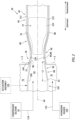
FIG. 2 illustrates a cutaway view of theburner 36 along anaxial centerline 64 of theburner 36. Theburner 36 ofFIG. 2 includes anouter wall 66 and aninner nozzle 68. Theaxial centerline 64 may be the same as or different than the rotational axis 46 (seeFIG. 1 ). - The
outer wall 66 extends circumferentially about (e.g., completely around) theaxial centerline 64. Theouter wall 66 forms anouter nozzle 70. Theouter nozzle 70 extends axially downstream from an upstreamaxial end 72 of theouter nozzle 70. The terms "upstream" and "downstream," as used herein with respect to theburner 36, refer to a general direction of fluid flow (e.g., air, hydrogen, fuel, etc.) through theburner 36 during operation of the gas turbine engine 20 (seeFIG. 1 ). Theouter nozzle 70 surrounds and forms acombustion chamber 74 of theburner 36, whichcombustion chamber 74 extends along theaxial centerline 64. The upstreamaxial end 72 is disposed at (e.g., on, adjacent, or proximate) ahydrogen manifold 76. Theouter wall 66 may form a portion of a housing for thehydrogen manifold 76, however, the present disclosure is not limited to this particular configuration of theouter wall 66. Thehydrogen manifold 76 may extend circumferentially about (e.g., completely around) theaxial centerline 64 at (e.g., on, adjacent, or proximate) the upstreamaxial end 72. Thehydrogen manifold 76 is connected in fluid communication with thecombustion chamber 74 to direct a hydrogen fuel flow into thecombustion chamber 74, as will be discussed in further detail. Theouter nozzle 70 includes a convergingaxial portion 78, a divergingaxial portion 80, and a downstreamaxial portion 82. - The converging
axial portion 78 forms an inlet of theouter nozzle 70. The convergingaxial portion 78 extends (e.g., axially extends) from the upstreamaxial end 72 to a downstream axial end 84 of the convergingaxial portion 78. The convergingaxial portion 78 extends circumferentially about (e.g., completely around) theaxial centerline 64. The convergingaxial portion 78 surrounds and forms a portion (e.g., an axial portion) of thecombustion chamber 74. The convergingaxial portion 78 converges radially toward theaxial centerline 64 in a direction from the upstreamaxial end 72 to the downstream axial end 84 such that the downstream axial end 84 is disposed radially inward of the upstreamaxial end 72. The convergingaxial portion 78 may converge (e.g., continuously converge) from the upstreamaxial end 72 to the downstream axial end 84. Accordingly, a diameter of thecombustion chamber 74 at the upstreamaxial end 72 is greater than a diameter of thecombustion chamber 74 at the downstream axial end 84. - The diverging
axial portion 80 is disposed axially downstream of the convergingaxial portion 78. The divergingaxial portion 80 extends (e.g., axially extends) from an upstream axial end 86 of the divergingaxial portion 80 to a downstreamaxial end 88 of the divergingaxial portion 80. For example, the upstream axial end 86 may be disposed at (e.g., on, adjacent, or proximate) the downstream axial end 84 such that the diverging axial portion extends (e.g., axially extends) from the downstream axial end 84 to the downstreamaxial end 88. The diverging axial portion 86 may include a constant-diameter axial portion 90. The constant-diameter axial portion 90 may be disposed at (e.g., on, adjacent, or proximate) the upstream axial end 86. - The
outer nozzle 70 forms a continuous curvature surface 128 (e.g., a second-derivative curvature surface) at an intersection of the convergingaxial portion 78 and the diverging axial portion 80 (e.g., portions of the convergingaxial portion 78 and the divergingaxial portion 80 including the downstream axial end 84 and the upstream axial end 86). In other words, the flow surface interface of the convergingaxial portion 78 and the divergingaxial portion 80 does not include any sharp angles, edges, steps, or the like. Thecontinuous curvature surface 128 extends circumferentially about (e.g., completely around) theaxial centerline 64. - The diverging
axial portion 80 extends circumferentially about (e.g., completely around) theaxial centerline 64. The divergingaxial portion 80 surrounds and forms a portion (e.g., an axial portion) of thecombustion chamber 74. The divergingaxial portion 80 diverges radially from theaxial centerline 64 in a direction from the upstream axial end 86 to the downstreamaxial end 88 such that the downstreamaxial end 88 is disposed radially outward of the upstream axial end 86. The divergingaxial portion 80 may diverge (e.g., continuously diverge) from the upstream axial end 86 to the downstreamaxial end 88. Accordingly, a diameter of thecombustion chamber 74 at the upstream axial end 86 is less than a diameter of thecombustion chamber 74 at the downstreamaxial end 88. The diverging axial portion 80 (e.g., an inner radial surface of theouter wall 66 in the diverging axial portion 80) may be oriented at a divergence angle Θ relative to theaxial centerline 64. For example, the divergence angle Θ may represent an average orientation of the divergingaxial portion 80 relative to theaxial centerline 64 extending from the upstream axial end 86 to the downstreamaxial end 88. The divergence angle Θ may be in a range between four and seven degrees (4-7°), however, the present disclosure is not limited to this particular divergence angle Θ. - The downstream
axial portion 82 extends (e.g., axially extends) axially downstream from the downstreamaxial end 88. The downstreamaxial portion 82 extends circumferentially about (e.g., completely around) theaxial centerline 64. The downstreamaxial portion 82 surrounds and forms a portion (e.g., an axial portion) of thecombustion chamber 74. The downstreamaxial portion 82 may have a cylindrical or substantially cylindrical shape. For example, thecombustion chamber 74 may have a constant diameter axially throughout the downstreamaxial portion 82. - The
inner nozzle 68 includes anozzle body 92. Thenozzle body 92 extends circumferentially about (e.g., completely around) theaxial centerline 64. Thenozzle body 92 surrounds and forms anair passage 94 of theinner nozzle 68, whichair passage 94 extends along theaxial centerline 64. Theair passage 94 is connected in fluid communication with the compressor section 24 (e.g., the high-pressure compressor 34) to receive compressed air from the compressor section 24 (seeFIG. 1 ). Thenozzle body 92 is configured to direct the compressed air from theair passage 94 into thecombustion chamber 74, as will be discussed in further detail. Thenozzle body 92 may form a portion of or otherwise be disposed within thehydrogen manifold 76. - The
nozzle body 92 includes a convergingaxial portion 96 at (e.g., on, adjacent, or proximate) a downstream axial end 98 (e.g., a distal end) of thenozzle body 92. The convergingaxial portion 96 extends (e.g., axially extends) from an upstreamaxial end 100 of the convergingaxial portion 96 to the downstreamaxial end 98. The convergingaxial portion 96 has a length L1 extending between and to the upstreamaxial end 100 and the downstreamaxial end 98 along theaxial centerline 64. The convergingaxial portion 96 extends circumferentially about (e.g., completely around) theaxial centerline 64. The convergingaxial portion 96 surrounds and forms a portion (e.g., an axial portion) of theair passage 94. The convergingaxial portion 96 converges radially toward theaxial centerline 64 in a direction from the upstreamaxial end 100 to the downstreamaxial end 98 such that the downstreamaxial end 98 is disposed radially inward of the upstreamaxial end 100. The convergingaxial portion 96 may converge (e.g., continuously converge) from the upstreamaxial end 100 to the downstreamaxial end 98. Accordingly, a diameter of theair passage 94 at the upstreamaxial end 98 is greater than a diameter of theair passage 94 at the downstreamaxial end 98. Thenozzle body 92 may additionally include an upstreamaxial portion 102 extending (e.g., axially extending) in an upstream direction from the upstreamaxial end 100. The upstreamaxial portion 102 ofFIG. 2 has a generally cylindrical shape, however, the present disclosure is not limited to any particular configuration of the upstreamaxial portion 102. - The converging
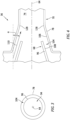
axial portion 96 is disposed radially inward of the convergingaxial portion 78 to form anannular gap 104 between the convergingaxial portion 96 and the convergingaxial portion 78.FIG. 3 illustrates a cross-sectional view of theburner 36 showing theannular gap 104. Theannular gap 104 extends circumferentially about (e.g., completely around) theaxial centerline 64. Theinner nozzle 68 is disposed relative to theouter nozzle 70 with the downstreamaxial end 98 disposed axially between (e.g., axially spaced from) the upstreamaxial end 72 and the downstream axial end 84. The upstreamaxial end 96 is disposed axially upstream of the upstreamaxial end 72. -
FIG. 4 illustrates another cutaway view of theburner 36 in greater detail at the location of theannular gap 104. The convergingaxial portion 78 of theouter nozzle 70 includes an outer convergingsurface 106 facing the convergingaxial portion 96 of theinner nozzle 68. The convergingaxial portion 96 of theinner nozzle 68 includes an inner convergingsurface 108 facing the convergingaxial portion 78 of theouter nozzle 70. The outer convergingsurface 106 and the inner convergingsurface 108 form theannular gap 104. The outer convergingsurface 106 and the inner convergingsurface 108 may be oriented parallel or substantially parallel to one another. The outer convergingsurface 106 and the inner convergingsurface 108 are configured to direct ahydrogen fuel flow 110 through theannular gap 104 into thecombustion chamber 74. Thehydrogen fuel flow 110 is schematically illustrated inFIG. 4 using a hydrogen fuel flow vector indicating a general direction of hydrogen gas flow through theannular gap 104 and into thecombustion chamber 74. Thehydrogen fuel flow 110 is directed through theannular gap 104 and into thecombustion chamber 74 in a direction toward theaxial centerline 64. In particular, thehydrogen fuel flow 110 is directed through theannular gap 104 and into thecombustion chamber 74 at an angle α relative to theaxial centerline 64, as shown inFIG. 4 . One or both of the outer convergingsurface 106 and the inner convergingsurface 108 may extend parallel to or substantially parallel to (e.g., +/- five degrees (5°)) the angle α in an upstream to downstream direction. The angle α is not limited to any particular value (e.g., the angle α may be greater than 0 degrees and less than 90 degrees), however, orientations of the outer convergingsurface 106 and the inner convergingsurface 108 may be selected to determine the angle α for different applications. As an example, the angle α for theburner 26 may be determined based on an expected Reynolds number (e.g., a ratio of inertial and viscous forces of a fluid flow) for fluid (e.g., hydrogen) flow through theburner 36 during operation of theburner 36. For smaller gas turbine engines, the expected Reynolds number may be relatively smaller and, therefore, a value of the angle α may also be relatively smaller. For larger gas turbine engines, the expected Reynolds number may be relatively larger and, therefore, a value of the angle α may also be relatively larger. - Referring again to
FIG. 2 , in operation of theburner 36, theinner nozzle 68 and theouter nozzle 70 direct ahydrogen fuel 116 and acompressed air 118 into thecombustion chamber 74 for mixing and combustion within thecombustion chamber 74. Thehydrogen fuel 116 may be supplied to thehydrogen manifold 76 from a hydrogen source 120 (e.g., a pressurized hydrogen storage tank) connected in fluid communication with thehydrogen manifold 76. Thehydrogen source 120 may be connected in fluid communication with thehydrogen manifold 76, in part, by one or more valves, regulators, or other fluid control devices to modulate a flow rate and/or pressure of thehydrogen fuel 116 supplied to thehydrogen manifold 76. Thehydrogen fuel 116 stored by thehydrogen source 120 may be pure or substantially pure hydrogen (e.g., a fuel which is greater than or equal to ninety percent hydrogen by volume). Thehydrogen fuel 116 is directed into thecombustion chamber 74 through theannular gap 104 by the outer convergingsurface 106 and the inner convergingsurface 108 along the angle α (seeFIG. 4 ). Thecompressed air 118 from the compressor section 24 (e.g., the high-pressure compressor 34) is directed through theair passage 94 into thecombustion chamber 74 by theinner nozzle 68. Thehydrogen fuel 116 mixes with thecompressed air 118 downstream of the inner nozzle 68 (e.g., the downstream axial end 98). - In general, the
hydrogen fuel 116 and thecompressed air 118 may be directed into thecombustion chamber 74 to achieve a hydrogen-to-air stoichiometric ratio of approximately 4:1 to approximately 10:1. The present disclosure, however, is not limited to any particular hydrogen-to-air stoichiometric ratio. A flow rate of thehydrogen fuel 116 into thecombustion chamber 74 may be controlled, for example, by controlling a flow rate of thehydrogen fuel 116 supplied to thehydrogen manifold 76 by thehydrogen source 120. Additionally or alternatively, the flow rate of thehydrogen fuel 116 into thecombustion chamber 74 may be controlled by controlling an axial position of theinner nozzle 68 relative to theouter nozzle 70. For example, theburner 36 may include anactuation assembly 126 configured to effect translation of theinner nozzle 68 along theaxial centerline 64 to control a size (e.g., a cross-sectional area perpendicular to the axial centerline 64) of theannular gap 104, thereby controlling a flow rate of thehydrogen fuel 116 through theannular gap 104. Theactuation assembly 126 may be formed by any linear actuation assembly conventionally known in the art (e.g., a hydraulic actuation assembly, a pneumatic actuation assembly, an electro-mechanical actuation assembly, etc.), and the present disclosure is not limited to any particular configuration of theactuation assembly 126. Alternatively, theinner nozzle 68 may be positionally (e.g., axially) fixed relative to theouter nozzle 70. - As the
hydrogen fuel 116 is directed into thecombustion chamber 74 within the convergingaxial portion 78 and at the angle α, at least some of thehydrogen fuel 116 remains attached to and flows along theouter wall 66, thereby forming ahydrogen film 122 along theouter wall 66. Thecontinuous curvature surface 128 and the angle α of thehydrogen fuel 116 guide a portion of thehydrogen fuel 116 onto theouter wall 66 without substantial mixing of the portion of thehydrogen fuel 116 with other gases in thecombustion chamber 74, thereby facilitating the formation of thehydrogen film 122 along theouter wall 66. At a same velocity, thehydrogen fuel 116 forming thehydrogen film 122 may have a significantly lower Reynolds number (e.g., a ratio of inertial and viscous forces of a fluid flow) in comparison to thecompressed air 118, thereby facilitating stability of thehydrogen film 122 along theouter wall 66 for all or a substantial portion of an axial length of thecombustion chamber 74. Instead of mixing with thecompressed air 118 and combusting, thehydrogen fuel 116 forming thehydrogen film 122 may form a relatively cooler fluid barrier along theouter wall 66, thereby protecting theouter wall 66 from flame contact and from the relatively hotter combustion gases (e.g., high-temperature H2O, N2, and O2) found in a high-temperature combustion region 124 of thecombustion chamber 74. The configuration of theinner nozzle 68 and theouter nozzle 70 for directing thehydrogen fuel 116 into thecombustion chamber 74 further facilitates flame stability within thecombustion chamber 74 by maintaining a high-turbulence backflow region (e.g., a trapped vortex) within the high-temperature combustion region 124, which facilitates continuous re-ignition and fuel-air mixing. This high-turbulence backflow region is bounded and stabilized by the incomingcompressed air 118 in upstream axial direction and by thecold hydrogen film 122 in the outer radial direction. - While the principles of the disclosure have been described above in connection with specific apparatuses and methods, it is to be clearly understood that this description is made only by way of example and not as limitation on the scope of the disclosure. Specific details are given in the above description to provide a thorough understanding of the embodiments. However, it is understood that the embodiments may be practiced without these specific details.
- It is noted that the embodiments may be described as a process which is depicted as a flowchart, a flow diagram, a block diagram, etc. Although any one of these structures may describe the operations as a sequential process, many of the operations can be performed in parallel or concurrently. In addition, the order of the operations may be rearranged. A process may correspond to a method, a function, a procedure, a subroutine, a subprogram, etc.
- The singular forms "a," "an," and "the" refer to one or more than one, unless the context clearly dictates otherwise. For example, the term "comprising a specimen" includes single or plural specimens and is considered equivalent to the phrase "comprising at least one specimen." The term "or" refers to a single element of stated alternative elements or a combination of two or more elements unless the context clearly indicates otherwise. As used herein, "comprises" means "includes." Thus, "comprising A or B," means "including A or B, or A and B," without excluding additional elements.
- It is noted that various connections are set forth between elements in the present description and drawings (the contents of which are included in this disclosure by way of reference). It is noted that these connections are general and, unless specified otherwise, may be direct or indirect and that this specification is not intended to be limiting in this respect. Any reference to attached, fixed, connected or the like may include permanent, removable, temporary, partial, full and/or any other possible attachment option.
- No element, component, or method step in the present disclosure is intended to be dedicated to the public regardless of whether the element, component, or method step is explicitly recited in the claims. No claim element herein is to be construed under the provisions of 35 U.S.C. 112(f) unless the element is expressly recited using the phrase "means for." As used herein, the terms "comprise", "comprising", or any other variation thereof, are intended to cover a non-exclusive inclusion, such that a process, method, article, or apparatus that comprises a list of elements does not include only those elements but may include other elements not expressly listed or inherent to such process, method, article, or apparatus.
- While various inventive aspects, concepts and features of the disclosures may be described and illustrated herein as embodied in combination in the exemplary embodiments, these various aspects, concepts, and features may be used in many alternative embodiments, either individually or in various combinations and sub-combinations thereof. Unless expressly excluded herein all such combinations and sub-combinations are intended to be within the scope of the present application. Still further, while various alternative embodiments as to the various aspects, concepts, and features of the disclosures--such as alternative materials, structures, configurations, methods, devices, and components, and so on--may be described herein, such descriptions are not intended to be a complete or exhaustive list of available alternative embodiments, whether presently known or later developed. Those skilled in the art may readily adopt one or more of the inventive aspects, concepts, or features into additional embodiments and uses within the scope of the present application even if such embodiments are not expressly disclosed herein. For example, in the exemplary embodiments described above within the Detailed Description portion of the present specification, elements may be described as individual units and shown as independent of one another to facilitate the description. In alternative embodiments, such elements may be configured as combined elements.
Claims (15)
- An assembly for a gas turbine engine, the assembly comprising:
at least one burner (36) including:an outer nozzle (70) extending circumferentially about an axial centerline (64) to form a combustion chamber (74) within the outer nozzle (70), the outer nozzle (70) includes an outer converging axial portion (78) and an outer diverging axial portion (80), the outer converging axial portion (78) is disposed at an upstream axial end (72) of the outer nozzle (70), and the outer diverging axial portion (80) is disposed axially downstream of the outer converging axial portion (78); andan inner nozzle (68) extending circumferentially about the axial centerline (64), the inner nozzle (68) including an inner converging axial portion (96) at a downstream axial end (98) of the inner nozzle (68), and the inner converging axial portion (96) is disposed within the outer converging axial portion (78) to form an annular gap (104) between the outer converging axial portion (78) and the inner converging axial portion (96); anda hydrogen manifold (76) disposed at the upstream axial end (72), and the hydrogen manifold (76) being connected in fluid communication with the annular gap (104). - The assembly of claim 1, wherein the outer converging axial portion (78) extends between and to a first axial end and a second axial end, and the downstream axial end (98) is disposed axially between the first axial end and the second axial end.
- The assembly of claim 1 or 2, further comprising a compressor section (24) of the gas turbine engine (20), wherein the inner nozzle (68) surrounds and forms an air passage (94) along the axial centerline (64), and the inner nozzle (68) is connected in fluid communication with the compressor section (24) and configured to direct a compressed air from the compressor section (24) into the combustion chamber (74) through the air passage (94).
- The assembly of any preceding claim, wherein the outer diverging axial portion (80) extends between and to a first axial end and a second axial end, and the first axial end is disposed at the outer converging axial portion (78).
- The assembly of any preceding claim, wherein the outer nozzle (70) forms a continuous curvature surface (128) at an intersection of the outer diverging axial portion (80) and the outer converging axial portion (78).
- The assembly of any preceding claim, wherein the outer converging axial portion (78) includes an outer converging surface (106), the inner converging axial portion (96) includes an inner converging surface (108), and the outer converging surface (106) and the inner converging surface (108) are configured to direct a hydrogen fuel from the hydrogen manifold (76) into the combustion chamber (74) at an angle (α) toward the axial centerline (64), optionally wherein:the outer converging surface (106) is oriented parallel to the inner converging surface (108); and/orthe outer converging surface (106) and/or the inner converging surface (108) is oriented at the angle (α) relative to the axial centerline (64).
- The assembly of any preceding claim, wherein the outer nozzle (70) further includes a downstream axial portion (82) extending from the outer diverging axial portion (80) in a downstream direction, and the downstream axial portion (82) has a constant diameter.
- The assembly of any preceding claim, wherein:the inner nozzle (68) is axially translatable along the axial centerline (64) relative to the outer nozzle (70); orthe inner nozzle (68) is axially fixed relative to the outer nozzle (70).
- The assembly of any preceding claim, wherein the inner nozzle (68) extends through the hydrogen manifold (76).
- The assembly of any preceding claim, further comprising a turbine section (28) of the gas turbine engine (20), the turbine section (28) connected in fluid communication with the combustion chamber (74) and configured to receive a combustion gas flow from the combustion chamber (74).
- The assembly of any preceding claim, wherein the outer diverging axial portion (80) extends along an average divergence angle (Θ) between four degrees and seven degrees relative to the axial centerline (64).
- A gas turbine engine for an aircraft propulsion system, the gas turbine engine comprising: a compressor section (24) configured to form a compressed air; and
at least one burner (36) including:a hydrogen manifold (76);an outer nozzle (70) extending circumferentially about an axial centerline (64) to form a combustion chamber (74) within the outer nozzle (70), the outer nozzle (70) includes an outer converging axial portion (78), the outer converging axial portion (78) is disposed at an upstream axial end (72) of the outer nozzle (70), and the upstream axial end (72) is disposed at the hydrogen manifold (76); andan inner nozzle (68) extending circumferentially about the axial centerline (64) to form an air passage (94) along the axial centerline (64), the inner nozzle (68) is connected in fluid communication with the compressor section (24) and configured to direct the compressed air from the compressor section (24) to the combustion chamber (74) through the air passage (94), and the inner nozzle (68) includes an inner converging axial portion (96) at a downstream axial end (98) of the inner nozzle (68);the outer converging axial portion (78) and the inner converging axial portion (96) form an annular gap (104), and the outer converging axial portion (78) and the inner converging axial portion (96) are configured to direct a hydrogen fuel from the hydrogen manifold (76) to the combustion chamber (74) through the annular gap (104). - The assembly of claim 12, wherein:the outer converging axial portion (78) extends between and to a first axial end and a second axial end, and the downstream axial end (98) is disposed axially between the first axial end and the second axial end; and/orthe outer converging portion includes an outer converging surface (106), the inner converging axial portion (96) includes an inner converging surface (108), and the outer converging surface (106) and the inner converging surface (108) are configured to direct the hydrogen fuel from the hydrogen manifold (76) into the combustion chamber (74) at an angle α toward the axial centerline (64).
- An assembly for a gas turbine engine, the assembly comprising:
at least one burner (36) including:an outer nozzle (70) extending circumferentially about an axial centerline (64) to form a combustion chamber (74) within the outer nozzle (70), the outer nozzle (70) includes an outer converging axial portion (78) and an outer diverging axial portion (80), the outer converging axial portion (78) is disposed at an upstream axial end (72) of the outer nozzle (70), and the outer diverging axial portion (80) is disposed axially downstream of the outer converging axial portion (78); andan inner nozzle (68) extending circumferentially about the axial centerline (64), the inner nozzle including an inner converging axial portion (96) at a downstream axial end (98) of the inner nozzle (68);the outer converging axial portion (78) and the inner converging axial portion (96) form an annular gap (104) extending along an angle α toward the axial centerline (64). - The assembly of claim 14, wherein:the outer converging axial portion (78) extends between and to a first axial end and a second axial end, and the downstream axial end (98) is disposed axially between the first axial end and the second axial end; and/orthe outer diverging axial portion (80) extends between and to a first axial end and a second axial end, and the first axial end is disposed at the outer converging axial portion (78).
Applications Claiming Priority (1)
| Application Number | Priority Date | Filing Date | Title |
|---|---|---|---|
| US18/233,159 US12704253B2 (en) | 2023-08-11 | 2023-08-11 | Burner for an aircraft gas turbine engine |
Publications (1)
| Publication Number | Publication Date |
|---|---|
| EP4528165A1 true EP4528165A1 (en) | 2025-03-26 |
Family
ID=92300938
Family Applications (1)
| Application Number | Title | Priority Date | Filing Date |
|---|---|---|---|
| EP24193971.9A Pending EP4528165A1 (en) | 2023-08-11 | 2024-08-09 | Burner for an aircraft gas turbine engine |
Country Status (3)
| Country | Link |
|---|---|
| US (1) | US12704253B2 (en) |
| EP (1) | EP4528165A1 (en) |
| CA (1) | CA3251436A1 (en) |
Citations (3)
| Publication number | Priority date | Publication date | Assignee | Title |
|---|---|---|---|---|
| US20060260316A1 (en) * | 2005-05-23 | 2006-11-23 | Power Systems Mfg., Llc | Flashback Suppression System for a Gas Turbine Combustor |
| EP2503241A1 (en) * | 2011-03-22 | 2012-09-26 | Siemens Aktiengesellschaft | Gas turbine burner |
| US20140182294A1 (en) * | 2011-09-05 | 2014-07-03 | Kawasaki Jukogyo Kabushiki Kaisha | Gas turbine combustor |
Family Cites Families (8)
| Publication number | Priority date | Publication date | Assignee | Title |
|---|---|---|---|---|
| US915991A (en) * | 1908-10-07 | 1909-03-23 | Egbert R Morrison | Controlling-valve. |
| US2594797A (en) * | 1949-08-13 | 1952-04-29 | Ray Oil Burner Co | Gas burner |
| JPS6014256B2 (en) | 1979-11-27 | 1985-04-12 | 工業技術院長 | Low NOx burner for hydrogen |
| US5240409A (en) * | 1992-04-10 | 1993-08-31 | Institute Of Gas Technology | Premixed fuel/air burners |
| US6162049A (en) * | 1999-03-05 | 2000-12-19 | Gas Research Institute | Premixed ionization modulated extendable burner |
| DE19917662C2 (en) | 1999-04-19 | 2001-10-31 | Elco Kloeckner Heiztech Gmbh | Burners for liquid and / or gaseous fuel |
| US12297774B2 (en) | 2021-04-29 | 2025-05-13 | General Electric Company | Fuel mixer |
| US11754282B2 (en) | 2021-06-23 | 2023-09-12 | Zeeco, Inc. | Lean pre-mix radiant wall burner apparatus and method |
-
2023
- 2023-08-11 US US18/233,159 patent/US12704253B2/en active Active
-
2024
- 2024-08-09 EP EP24193971.9A patent/EP4528165A1/en active Pending
- 2024-08-09 CA CA3251436A patent/CA3251436A1/en active Pending
Patent Citations (3)
| Publication number | Priority date | Publication date | Assignee | Title |
|---|---|---|---|---|
| US20060260316A1 (en) * | 2005-05-23 | 2006-11-23 | Power Systems Mfg., Llc | Flashback Suppression System for a Gas Turbine Combustor |
| EP2503241A1 (en) * | 2011-03-22 | 2012-09-26 | Siemens Aktiengesellschaft | Gas turbine burner |
| US20140182294A1 (en) * | 2011-09-05 | 2014-07-03 | Kawasaki Jukogyo Kabushiki Kaisha | Gas turbine combustor |
Also Published As
| Publication number | Publication date |
|---|---|
| US20250052418A1 (en) | 2025-02-13 |
| US12704253B2 (en) | 2026-08-11 |
| CA3251436A1 (en) | 2025-06-04 |
Similar Documents
| Publication | Publication Date | Title |
|---|---|---|
| US10837640B2 (en) | Combustion section of a gas turbine engine | |
| CN109028142B (en) | Propulsion system and method of operating the same | |
| US11371439B2 (en) | Fuel staging system | |
| EP3181829B1 (en) | Gas turbine engine turbine cooling system | |
| US11788725B2 (en) | Trapped vortex combustor for a gas turbine engine with a driver airflow channel | |
| US20250290467A1 (en) | Propulsion system using ramjet bleed air for gas turbine combustion | |
| US20200025111A1 (en) | Metering valve assembly and method of assembly thereof | |
| US12553403B1 (en) | Gas turbine engine having a thrust reverser system with drag link connectors at inter-compressor frame structure | |
| WO2024096879A1 (en) | Gas turbine engine with third stream | |
| US20250052418A1 (en) | Burner for an aircraft gas turbine engine | |
| US20250020082A1 (en) | Fuel nozzle valve seals for high temperature | |
| EP4477949A1 (en) | Gaseous fuel and liquid water injection for turbine engine | |
| US20250283432A1 (en) | Fuel injector cooling system | |
| US12486856B2 (en) | Diffuser pipe for an aircraft propulsion system | |
| US12601493B2 (en) | Combustors and methods of mitigating thermoacoustic instabilities in a gas flow | |
| US12504169B2 (en) | Gas turbine engine | |
| EP3757353B1 (en) | Insert for a collector of an active clearance control system of an engine of an aircraft | |
| US11905837B2 (en) | Sealing system including a seal assembly between components | |
| CA3264058A1 (en) | Diffuser pipe for an aircraft propulsion system | |
| US11149692B2 (en) | Deflection mitigation structure for combustion system | |
| US11867392B1 (en) | Combustor with tangential fuel and air flow |
Legal Events
| Date | Code | Title | Description |
|---|---|---|---|
| PUAI | Public reference made under article 153(3) epc to a published international application that has entered the european phase |
Free format text: ORIGINAL CODE: 0009012 |
|
| STAA | Information on the status of an ep patent application or granted ep patent |
Free format text: STATUS: THE APPLICATION HAS BEEN PUBLISHED |
|
| AK | Designated contracting states |
Kind code of ref document: A1 Designated state(s): AL AT BE BG CH CY CZ DE DK EE ES FI FR GB GR HR HU IE IS IT LI LT LU LV MC ME MK MT NL NO PL PT RO RS SE SI SK SM TR |
|
| STAA | Information on the status of an ep patent application or granted ep patent |
Free format text: STATUS: REQUEST FOR EXAMINATION WAS MADE |
|
| 17P | Request for examination filed |
Effective date: 20250926 |