EP4528116A1 - Sleeve and frame fastener - Google Patents
Sleeve and frame fastener Download PDFInfo
- Publication number
- EP4528116A1 EP4528116A1 EP24200899.3A EP24200899A EP4528116A1 EP 4528116 A1 EP4528116 A1 EP 4528116A1 EP 24200899 A EP24200899 A EP 24200899A EP 4528116 A1 EP4528116 A1 EP 4528116A1
- Authority
- EP
- European Patent Office
- Prior art keywords
- screw
- sleeve
- frame
- head
- channel
- Prior art date
- Legal status (The legal status is an assumption and is not a legal conclusion. Google has not performed a legal analysis and makes no representation as to the accuracy of the status listed.)
- Pending
Links
Images




Classifications
-
- E—FIXED CONSTRUCTIONS
- E06—DOORS, WINDOWS, SHUTTERS, OR ROLLER BLINDS IN GENERAL; LADDERS
- E06B—FIXED OR MOVABLE CLOSURES FOR OPENINGS IN BUILDINGS, VEHICLES, FENCES OR LIKE ENCLOSURES IN GENERAL, e.g. DOORS, WINDOWS, BLINDS, GATES
- E06B1/00—Border constructions of openings in walls, floors, or ceilings; Frames to be rigidly mounted in such openings
- E06B1/56—Fastening frames to the border of openings or to similar contiguous frames
- E06B1/60—Fastening frames to the border of openings or to similar contiguous frames by mechanical means, e.g. anchoring means
- E06B1/6069—Separate spacer means acting exclusively in the plane of the opening; Shims; Wedges; Tightening of a complete frame inside a wall opening
- E06B1/6076—Separate spacer means acting exclusively in the plane of the opening; Shims; Wedges; Tightening of a complete frame inside a wall opening of screw-type
-
- F—MECHANICAL ENGINEERING; LIGHTING; HEATING; WEAPONS; BLASTING
- F16—ENGINEERING ELEMENTS AND UNITS; GENERAL MEASURES FOR PRODUCING AND MAINTAINING EFFECTIVE FUNCTIONING OF MACHINES OR INSTALLATIONS; THERMAL INSULATION IN GENERAL
- F16B—DEVICES FOR FASTENING OR SECURING CONSTRUCTIONAL ELEMENTS OR MACHINE PARTS TOGETHER, e.g. NAILS, BOLTS, CIRCLIPS, CLAMPS, CLIPS OR WEDGES; JOINTS OR JOINTING
- F16B25/00—Screws that cut thread in the body into which they are screwed, e.g. wood screws
- F16B25/001—Screws that cut thread in the body into which they are screwed, e.g. wood screws characterised by the material of the body into which the screw is screwed
- F16B25/0015—Screws that cut thread in the body into which they are screwed, e.g. wood screws characterised by the material of the body into which the screw is screwed the material being a soft organic material, e.g. wood or plastic
-
- F—MECHANICAL ENGINEERING; LIGHTING; HEATING; WEAPONS; BLASTING
- F16—ENGINEERING ELEMENTS AND UNITS; GENERAL MEASURES FOR PRODUCING AND MAINTAINING EFFECTIVE FUNCTIONING OF MACHINES OR INSTALLATIONS; THERMAL INSULATION IN GENERAL
- F16B—DEVICES FOR FASTENING OR SECURING CONSTRUCTIONAL ELEMENTS OR MACHINE PARTS TOGETHER, e.g. NAILS, BOLTS, CIRCLIPS, CLAMPS, CLIPS OR WEDGES; JOINTS OR JOINTING
- F16B25/00—Screws that cut thread in the body into which they are screwed, e.g. wood screws
- F16B25/001—Screws that cut thread in the body into which they are screwed, e.g. wood screws characterised by the material of the body into which the screw is screwed
- F16B25/0031—Screws that cut thread in the body into which they are screwed, e.g. wood screws characterised by the material of the body into which the screw is screwed the screw being designed to be screwed into different materials, e.g. a layered structure or through metallic and wooden parts
-
- F—MECHANICAL ENGINEERING; LIGHTING; HEATING; WEAPONS; BLASTING
- F16—ENGINEERING ELEMENTS AND UNITS; GENERAL MEASURES FOR PRODUCING AND MAINTAINING EFFECTIVE FUNCTIONING OF MACHINES OR INSTALLATIONS; THERMAL INSULATION IN GENERAL
- F16B—DEVICES FOR FASTENING OR SECURING CONSTRUCTIONAL ELEMENTS OR MACHINE PARTS TOGETHER, e.g. NAILS, BOLTS, CIRCLIPS, CLAMPS, CLIPS OR WEDGES; JOINTS OR JOINTING
- F16B25/00—Screws that cut thread in the body into which they are screwed, e.g. wood screws
- F16B25/0036—Screws that cut thread in the body into which they are screwed, e.g. wood screws characterised by geometric details of the screw
- F16B25/0042—Screws that cut thread in the body into which they are screwed, e.g. wood screws characterised by geometric details of the screw characterised by the geometry of the thread, the thread being a ridge wrapped around the shaft of the screw
- F16B25/0057—Screws that cut thread in the body into which they are screwed, e.g. wood screws characterised by geometric details of the screw characterised by the geometry of the thread, the thread being a ridge wrapped around the shaft of the screw the screw having distinct axial zones, e.g. multiple axial thread sections with different pitch or thread cross-sections
-
- F—MECHANICAL ENGINEERING; LIGHTING; HEATING; WEAPONS; BLASTING
- F16—ENGINEERING ELEMENTS AND UNITS; GENERAL MEASURES FOR PRODUCING AND MAINTAINING EFFECTIVE FUNCTIONING OF MACHINES OR INSTALLATIONS; THERMAL INSULATION IN GENERAL
- F16B—DEVICES FOR FASTENING OR SECURING CONSTRUCTIONAL ELEMENTS OR MACHINE PARTS TOGETHER, e.g. NAILS, BOLTS, CIRCLIPS, CLAMPS, CLIPS OR WEDGES; JOINTS OR JOINTING
- F16B37/00—Nuts or like thread-engaging members
- F16B37/12—Nuts or like thread-engaging members with thread-engaging surfaces formed by inserted coil-springs, discs, or the like; Independent pieces of wound wire used as nuts; Threaded inserts for holes
- F16B37/122—Threaded inserts, e.g. "rampa bolts"
- F16B37/125—Threaded inserts, e.g. "rampa bolts" the external surface of the insert being threaded
- F16B37/127—Threaded inserts, e.g. "rampa bolts" the external surface of the insert being threaded and self-tapping
-
- F—MECHANICAL ENGINEERING; LIGHTING; HEATING; WEAPONS; BLASTING
- F16—ENGINEERING ELEMENTS AND UNITS; GENERAL MEASURES FOR PRODUCING AND MAINTAINING EFFECTIVE FUNCTIONING OF MACHINES OR INSTALLATIONS; THERMAL INSULATION IN GENERAL
- F16B—DEVICES FOR FASTENING OR SECURING CONSTRUCTIONAL ELEMENTS OR MACHINE PARTS TOGETHER, e.g. NAILS, BOLTS, CIRCLIPS, CLAMPS, CLIPS OR WEDGES; JOINTS OR JOINTING
- F16B5/00—Joining sheets or plates, e.g. panels, to one another or to strips or bars parallel to them
- F16B5/02—Joining sheets or plates, e.g. panels, to one another or to strips or bars parallel to them by means of fastening members using screw-thread
- F16B5/0283—Joining sheets or plates, e.g. panels, to one another or to strips or bars parallel to them by means of fastening members using screw-thread with an externally threaded sleeve around the neck or the head of the screw-threaded element for adjustably fastening a plate or frame or the like to a fixed element
Definitions
- Fasteners are used to install a frame, such as a window frame or door frame, into a wall at one or more desired locations.
- An opening is typically provided in the wall, and the frame is secured within the opening to the wall. This provides lasting support for holding a window or door within the frame, allowing it to open and close relative to the wall.
- a fastener used to install a frame into a wall of a building is a frame fastener, which is also known as a frame screw.
- the frame fastener includes a sleeve with a threaded outer casing and a fixing in the form of a screw.
- the frame fastener is inserted into the frame and into the wall.
- the wall may be made of masonry, in particular brick, concrete, concrete blocks, stone, wood or another material.
- different fasteners are generally required depending on the material of the wall, to provide the desired physical properties to facilitate the installation of the frame to the wall, such as pull-out strength, hardness, wear-resistance and insertion torque, for example.
- a sleeve for receiving a screw to secure a frame, for example a window frame or a door frame, to a wall, comprising: a threaded outer surface configured to screw into the frame; and a through-channel defining a central axis of the sleeve, comprising a sloped portion that is angled relative to the central axis for central alignment of a screw when the screw is inserted into the through-channel of the sleeve.
- the sloped portion of the through-channel is arranged in direct contact with the screw. In some examples, the sloped portion of the through-channel is arranged in direct contact with a head portion of the screw.
- the through-channel comprises a screw abutment surface.
- the screw abutment surface comprises a step for abutting a head flange of the screw.
- the sloped portion is configured for abutting a head portion of the screw.
- the sloped portion is arranged adjacent the screw abutment surface along the central axis of the sleeve. In some examples, the sloped portion is adjacent the screw abutment surface in a direction towards a head of the sleeve.
- the sloped portion has a frustoconical shape.
- the sloped portion tapers inwards in a direction from a tip to a head of the sleeve.
- the sloped portion forms an angle relative to the central axis that is between 0 and 10 degrees. In some examples, the sloped portion forms an angle relative to the central axis that is between 1 and 2 degrees. In some examples, the sloped portion forms an angle relative to the central axis that is between 1.5 and 2 degrees. In specific examples, the sloped portion forms an angle relative to the central axis that is 1.75 degrees.
- the sloped portion spans an axial length, along the central axis, of between 2.5 and 12mm. In some examples, the sloped portion spans an axial length, along the central axis, of between 4 and 8mm.
- the sleeve spans a length of between 25 to 40 millimetres.
- the sleeve comprises a head and an opposite tip.
- the head of the sleeve comprises a stopper flange.
- the stopper flange comprises circumferential teeth.
- the circumferential teeth may be circumferentially distributed around the stopper flange.
- the circumferential teeth may extend or protrude axially from the stopper flange towards the tip.
- the circumferential teeth may have a tip or a radial edge.
- the stopper flange comprises radial ribs extending towards the tip.
- the radial ribs may be circumferentially distributed around the stopper flange.
- the radial ribs may extend or protrude axially from the stopper flange towards the tip.
- the radial ribs may have a radial edge.
- the sleeve comprises reinforcement ribs arranged between the stopper flange and the threaded outer surface.
- the reinforcement ribs may extend or protrude radially from a tubular wall arranged between the stopper flange and the threaded outer surface.
- the reinforcement ribs may extend externally or internally from the tubular wall.
- the reinforcement ribs may be circumferentially distributed around the tubular wall.
- a frame fastener for securing a frame, for example a window frame or a door frame, to a wall, comprising: a sleeve comprising a threaded outer surface configured to screw into the frame, and a through-channel defining a central axis of the sleeve, the through-channel comprising a sloped portion that is angled relative to the central axis; and a screw having a head and a tip at opposite ends, and a shaft extending between the head and the tip, wherein the screw is sized and shaped to abut the sloped portion such that screw extends through the through-channel in alignment with the central axis.
- the sloped portion of the through-channel and the screw are in direct contact.
- the sloped portion of the through-channel and a head portion of the screw are in direct contact.
- the through-channel comprises a screw abutment surface.
- the screw abutment surface comprises a step for abutting a head flange of the screw.
- the sloped portion is configured for abutting a head portion of the screw.
- the head portion of the screw comprises a sloped profile.
- the sloped profile has a frustoconical shape.
- the sloped profile tapers inwards in a direction from the head to the tip of the screw.
- a screw having a head and a tip at opposite ends, and a shaft extending between the head and the tip to define a central axis of the screw, wherein the head of the screw comprises a sloped portion that is angled relative to the central axis of the screw.
- the sloped profile of the screw has a frustoconical shape.
- the sloped profile tapers inwards in a direction from the head to the tip of the screw.
- a frame fastener for securing a frame, for example a frame or a door frame, to a wall, comprising: a sleeve comprising a through-channel, a screw abutment surface, and a threaded outer surface configured to screw into the frame; and a screw having a head and a tip at opposite ends and a shaft extending between the head and the tip, wherein the head is sized to abut the screw abutment surface when the screw is inserted into the sleeve, wherein the shaft comprises a hardened cutting thread for screwing into masonry, and wherein the tip comprises a tapered portion having a cutting thread for screwing into wood.
- the frame fastener is provided with a screw that can be inserted both into softer materials such as wood, and into harder materials such as masonry.
- a frame fastener is multi-purpose and suitable for different types of materials. Therefore, the frame fastener removes the need to use different frame fasteners each only suitable for a single material or type of material.
- the frame fastener can be used to fasten frames to different types of materials.
- the hardened cutting thread is hardened by heat treatment.
- the hardened cutting thread is formed by thread rolling followed by heat treatment.
- the hardened cutting thread may be hardened by a quenching and tempering process. It may be hardened by case hardening, flame hardening, induction hardening, or laser hardening, for example.
- the whole screw is hardened to provide the hardened cutting thread.
- the whole screw is hardened by heating the screw in an oven (e.g. to 900 degrees Celsius) and then cooling the screw.
- the hardness of the screw is dependent on one or more of the carbon content of the screw, the carbon content in the oven, and the temperature of the oven and the duration the screw is in the oven.
- the whole screw is hardened to a first degree and the hardened cutting thread is hardened to a greater degree.
- the core hardness of the screw is between 425HV5 (Vickers hardness number of 425 at a load of 5kgf) and 475HV5 (Vickers hardness number of 425 at a load of 5kgf).
- the surface hardness of the hardened cutting thread is at least 650HV03 (Vickers hardness number of 650 at a load of 0.3kgf), for example between 650HV03 (Vickers hardness number of 650 at a load of 0.3kgf) and 750HV03 (Vickers hardness number of 750 at a load of 0.3kgf), for example about 650HV03 (Vickers hardness number of 650 at a load of 0.3kgf), for example about 750HV03 (Vickers hardness number of 750 at a load of 0.3kgf).
- the hardened surface of the hardening cutting thread may have a thickness of between 0.15mm to 0.3mm.
- the hardness of the core of the screw is dependent on one or more of the carbon content in the oven, the duration the screw is in the oven, and the temperature of the oven.
- the Vickers hardness test is performed on a flat surface. Therefore, a cut is made through a section of the screw where a hardness needs to be measured, and the tip of the indenter is positioned inside of the edge. This may be 0.1mm from the edge.
- a Vickers hardness test involves determining a hardness of a test material by measuring the size of an indent produced under load by a pyramid-shaped diamond indenter, having opposing sides that meet at an apex at an angle of 136°. The diamond indenter is pressed into the surface of the test material at a known load (measured in kgf) and the size of the impression is determined. The size of the impression may be measured using the diagonal length of the impression.
- the cutting thread is configured for splitting wood fibres.
- a thread angle of the cutting thread is less than a thread angle of the hardened cutting thread with respect to a longitudinal axis of the screw.
- a thread angle of the cutting thread with respect to a longitudinal axis of the screw is in a range of 5 degrees to 45 degrees.
- a thread angle of the hardened cutting thread with respect to a longitudinal axis of the screw is in a range of 45 degrees to 85 degrees.
- the screw is made of a material comprising steel. In examples, the screw is made of stainless steel.
- the screw abutment surface limits the movement of the head in an axial direction of the screw.
- the screw abutment surface is a stepped surface.
- the screw abutment surface is a flange.
- the sleeve comprises two screw abutment surfaces to limit the movement of the head of the screw between the screw abutment surfaces.
- the two screw abutment surfaces are stepped surfaces.
- the screw abutment surfaces are flanges.
- the hardened cutting thread is configured to screw into a pilot hole in the masonry, and wherein the maximum diameter of the cutting thread is less than the diameter of the pilot hole. This is advantageous because the portion of the screw with the cutting thread is inserted directly into the pilot hole without the cutting thread contacting the edges of the pilot hole, and the hardened cutting thread engages the edge of the pilot hole.
- the hardened cutting thread extends over the tapered portion of the tip.
- the cutting thread spans the length of the tapered portion of the tip.
- the cutting thread extends over the shaft of the screw.
- the screw abutment surface is a stepped surface between the ends of the sleeve.
- the stepped surface is between a first channel region and a second channel region, the first channel region being wider than the second channel region.
- the stepped surface is a flange.
- the second channel region is arranged to receive a cylindrical part of the screw.
- the provision of a second channel region arranged to receive a cylindrical part of the screw is particularly advantageous because the engagement and therefore axial alignment of the screw with the sleeve is increased, providing the frame fastener with improved structural rigidity and stability.
- the cylindrical part of the screw may be part of the screw that has no threads.
- the cylindrical part may have a smooth surface.
- the cylindrical part of the screw is between the head and the shaft of the screw.
- the cylindrical part of the screw is sized to correspond with the second channel region. This is advantageous because this further improves the axial alignment of the screw with the sleeve.
- the cylindrical part and the second channel region have the same axial length.
- the hardened cutting thread of the shaft comprises at least one notch.
- the provision of at least one notch is advantageous because dust generated from the insertion of the screw is trapped in the notch, reducing the amount of dust present in the surrounding area and improving the fixing of the screw into the wall.
- the notch is a cutting notch.
- the notch is a dust accumulating notch.
- dust may accumulate in the notch and be compressed, increasing the anchoring of the screw in the masonry.
- the thread of the shaft comprises a plurality of notches.
- the plurality of notches are linearly spaced from each other along adjacent turns of the thread.
- a screw for a frame fastener for securing a frame comprising a head and a tip at opposite ends, and a shaft extending between the head and the tip, wherein the head is sized to abut the screw abutment surface when the screw is inserted into the through-channel of the sleeve, and wherein the shaft comprises a hardened cutting thread for screwing into masonry, and wherein the tip comprises a tapered portion having a cutting thread for screwing into wood.
- the terms 'connected', 'attached', 'coupled' and 'mounted' are intended to include direct connections between two members without any other members interposed therebetween, as well as, indirect connections between members in which one or more other members are interposed therebetween.
- the terminology includes the words specifically mentioned above, derivatives thereof, and words of similar import.
- the sleeve 102 includes a through-channel 104, a screw abutment surface 106, and a threaded outer surface 112.
- the through-channel 104 is an opening that extends through the length of the sleeve 102.
- the screw abutment surface 106 is provided within the through-channel 104, partitioning the through-channel 104 into two regions having different diameters.
- the screw abutment surface 106 is provided as a stepped surface between a first channel region 108 and a second channel region 110.
- the first channel region 108 is larger in diameter (i.e. wider) than the second channel region 110.
- the tool-engaging portion 114 may be internal of the sleeve 102 and/or external of the sleeve 102. It is also envisaged that tool-engaging portions 114 may be included at both ends of the sleeve 102. One of the tool-engaging portions 114 may be internal, and another of the tool-engaging portions 114 may be external. Any of the tool-engaging portions 114 may be used to engage and screw the sleeve 102, for example using a hex key or a screwdriver.
- FIG. 2 shows a screw 202.
- the screw 202 has a head 204 arranged at a proximal end and a tip 206 arranged at a distal end.
- the head 204 of the screw 202 is provided with a recessed surface 218 for engagement of a screwdriver or tool.
- the head 204 of the screw 202 may include a different form of tool engaging socket or external shape, for example a hexagonal profile for a socket tool.
- Extending between the head 204 and the tip 206 is a shaft 208.
- the shaft 208 includes a hardened cutting thread 210.
- the hardened cutting thread 210 includes a plurality of threads that are hardened, for example by a heat treatment process.
- the hardened cutting thread 210 may be formed by a thread rolling process followed by heat treatment.
- the whole screw may be hardened to provide the hardened cutting thread, or the whole screw may be hardened to a first degree and the hardened cutting thread may be hardened to a greater degree.
- the hardened cutting thread 210 extends over a tapered portion 212 of the tip 206.
- the hardened cutting thread 210 includes a plurality of notches 216 that trap and compress dust when screwing into masonry to increase fixation.
- the notches 216 are linearly spaced from each other along adjacent turns of the thread.
- the screw 202 is made of steel, in particular stainless steel.
- the core hardness of the screw 202 is 450HV5 (Vickers hardness number of 450 at a load of 5kgf).
- the surface hardness of the hardened cutting thread 210 is 700HV03 (Vickers hardness number of 700 at a load of 0.3kgf). Having a cutting thread with a hardened surface is particularly beneficial for screwing into harder materials such as masonry because it has a high resistance to wear.
- the tip 206 of the screw 202 has a tapered portion 212 provided with a cutting thread 214.
- the tapered portion 212 is tapered in shape from the shaft 208 to the tip 206 of the screw 202.
- the cutting thread 214 spans the length of the tapered portion 212. In this example, the cutting thread 214 extends over a portion of the shaft 208 of the screw 202.
- the screw 202 has a cylindrical part 222 which is arranged between the head 204 and the shaft 208, and a shank 220 which is arranged between the cylindrical part 222 and the shaft 208.
- the thread angle of the cutting thread 214 is less than the thread angle of the hardened cutting thread 210, each thread angle being measured with respect to a longitudinal axis of the screw 202.
- the thread angle of the cutting thread 214 is adapted for wood fibre splitting.
- the thread angle of the of the hardened cutting thread 210 is adapted to screw into masonry and also into wood after splitting of the wood fibres.
- the thread angle of the cutting thread 214 may be in the range of 5 degrees to 45 degrees. Other ranges of thread angle of the cutting thread 214 are envisaged, for example: 10 to 35 degrees; 15 to 30 degrees; 15 to 20 degrees; and 16 to 18 degrees. In this particular example, the thread angle of the cutting thread 214 is 17 degrees.
- the thread angle of the hardened cutting thread 210 may be in the range of 45 degrees to 85 degrees. Other ranges of the thread angle of the hardened cutting thread 210 are envisaged, for example: 55 to 85 degrees; 60 to 80 degrees; 70 to 80 degrees; and 72 to 78 degrees. In this particular example, the thread angle of the hardened cutting thread 210 is 75 degrees. Other thread angles of the cutting thread 214 and hardened cutting thread 210 are envisaged.
- FIG. 3A and FIG. 3B show a frame fastener 100 which includes the sleeve 102 and screw 202 as previously described.
- the screw 202 when assembled, the screw 202 is inserted into the through-channel 104 of the sleeve 102 in a direction from the proximal end (i.e. tool-engaging portion 114 side) to the distal end (i.e. stopper flange 116 side).
- the head 204 of the screw 202 is sized such that it abuts the screw abutment surface 106 of the sleeve 102 upon insertion of the screw 202 into the sleeve 102.
- the screw abutment surface 106 limits the movement of the screw 202 in the axial direction.
- the cylindrical part 222 of the screw 202 is received in the second channel region 110 of the through-channel 104, which increases the engagement and the axial alignment of the screw 202 with the sleeve 102 and, in turn, improves the structural rigidity and stability of the frame fastener 100.
- the cylindrical part 222 of the screw 202 has an axial length that corresponds with the axial length of the second channel region 110.
- the frame fastener 100 is used to secure a frame 400 to a wall 410.
- the frame 400 is a window frame.
- the frame 400 may be a door frame.
- a hole 405 is drilled into the frame 400, and the sleeve 102 is inserted into the hole 405 from the outside (wall 410 side) before the frame 400 is placed into the opening of the wall 410.
- the sleeve 102 is screwed all the way into the frame 400 until the stopper flange 116 abuts the surface of the frame 400.
- the frame 400, with the sleeve 102 inserted inside, is positioned in the wall 410 opening.
- the sleeve 102 is then unscrewed from the inside until the stopper flange 116 abuts the surface of the wall 410. This holds the frame 400 in place relative to the wall 410.
- This process is repeated to secure the frame 400 to the wall 410 at different locations, and a check can be made to ensure that the frame 400 is level with the wall 410 and properly positioned.
- the screw 202 is inserted through the hole 405 in the frame 400 and through the sleeve 102 into the wall 410, to secure the frame fastener 100 together.
- An adjustment in the distance between the frame 400 and the wall 410 can later be made by loosening the screw 202, rotating the sleeve 102 in a direction depending on whether the sleeve 102 needs to be tightened or loosened, and then retightening the screw 202.
- the frame fastener 100 in particular the screw 202, can be used with different types of materials, for example softer materials such as wood, and harder materials such as masonry. Accordingly, the same frame fastener 100 can be used for openings with wood and/or masonry openings.
- the screw 202 may be inserted into a wall 410 made of a softer material such as wood.
- the cutting thread 214 provided on the tapered portion 212 of the tip 206 cuts into the wall 410 to create an opening for inserting the frame fastener 100.
- the hardened cutting thread 210 of the screw 202 engages with the edge of the opening in the wall 410 to secure the screw 202 to the wall 410.
- the cutting thread 214 may split the wood fibres in the wall 410 and the hardened cutting thread 210 can screw into the wood to secure it.
- the screw 202 may be inserted into a wall 410 made of a harder material such as concrete or other masonry.
- the wall 410 may include a pilot (i.e. pre-drilled) hole.
- the pilot hole may have a maximum diameter which is less than the diameter of the cutting thread 214.
- the frame fastener 100 can be inserted both into walls made of a softer material such as wood, and made of a harder material such as masonry.
- the frame fastener 100 is multi-purpose and suitable for different types of materials, removing the need to use different frame fasteners each only suitable for a single material or type of material.
- FIG. 5 shows an example of a frame fastener 100 with a sleeve 102 that is modified from the example previously described.
- the other aspects of the frame fastener 100 are the same so will not be described again here.
- the through-channel 104 of the sleeve 102 is provided with two screw abutment surfaces 106, 124.
- the two screw abutment surfaces 106, 124 limit the movement of the screw 202 within the sleeve 102. This traps the screw 202 within a predetermined region within the sleeve 102 defined by the two screw abutment surfaces 106, 124 of the through-channel 104.
- the screw 202 can freely rotate within the sleeve 102.
- the second screw abutment surface 124 may be a stepped surface towards the tool-engaging portion 114.
- Each of the screw abutment surfaces 106, 124 may be a stepped surface.
- the frame fastener 100 including both the sleeve 102 and the screw 202 is inserted into the hole 405 of the frame 400 and into the wall 410 from the inside.
- the screw 202 is screwed into the wall 410 while the sleeve 102 is rotated at the same time to screw into the frame 400, for example using a tool that simultaneously engages a hex socket in the sleeve 102 and a recessed surface 218 in the screw 202.
- the sleeve 102 can be screwed to be tightened or loosened, for example using a hex key to rotate the sleeve 102 independently from the screw 202. This moves the sleeve 102 relative to the screw 202, and therefore moves the frame 400 towards and away from the wall 410.
- FIG. 6A and FIG. 6B show another example of a sleeve 502 including a through-channel 504 defining a central axis 518, a screw abutment surface 506, and a threaded outer surface 512.
- the through-channel 504 is an opening that extends through the length of the sleeve 502 between a head of the sleeve 502 and an opposite tip.
- the through-channel 504 includes a sloped portion 520 that is angled relative to the central axis 518.
- the angle formed between the sloped portion 520 and central axis 518 is 1.75 degrees, although other angles are envisaged, for example between 0 (excluded) and 10 (included) degrees, between 1 and 2 degrees (included), or between 1.5 and 2 degrees (included).
- the sloped portion 520 is arranged adjacent the screw abutment surface 506 along the central axis 518, in particular in a direction towards a head of the sleeve 502.
- the sloped portion 520 tapers inwards in a direction from the tip to the head of the sleeve 502.
- the sloped portion 520 has a frustoconical shape.
- the sloped portion 520 spans an axial length, along the central axis 518, of between 2.5 and 12mm (included), or between 4 and 8mm (included).
- the threaded outer surface 512 is provided on an external outer surface of the sleeve 502.
- a proximal end (i.e. tip) of the sleeve 502 is provided with a tool-engaging portion 514.
- the proximal end of the sleeve 502 is also provided with cutting tips 530 which help the sleeve 502 cut into an installation hole.
- a distal end (i.e. head) of the sleeve 502 is provided with a stopper flange 516 having a diameter which is larger than the diameter of the threaded outer surface 512.
- the perimeter of the stopper flange 516 is provided with circumferential teeth 532 and radial ribs 534 that facilitate a flush installation and reduce splitting.
- the circumferential teeth 532 and radial ribs 534 extend or protrude axially from the stopper flange 516 towards the tip of sleeve 502.
- the circumferential teeth 532 may have a sharp tip.
- the radial ribs 534 may have a sharp radial edge.
- Arranged between the stopper flange 516 and the threaded outer surface 512 is a number of reinforcement ribs 522 improve the strength and stiffness of the sleeve 502.
- the reinforcement ribs 522 extend or protrude radially from a tubular wall arranged between the stopper flange 516 and the threaded outer surface 512. In this example, the reinforcement ribs 522 extend externally from the tubular wall although they could extend internally from the tubular wall. The reinforcement ribs 522 makes it possible to save material without compromising the strength of the sleeve 502.
- FIG. 7A and FIG. 7B show another example of a screw 602 having a tip 606, shaft 608, hardened cutting thread 610, tapered portion 612, cutting thread 614, notches 616, recessed surface 618, shank 620 that are the same as that of the screw 202 in FIG. 2 .
- the screw 602 has a head and a tip 606 at opposite ends, and a shaft 608 extending between the head and the tip 606.
- the head in this example includes a flange 604 and a head portion 624 extending from the flange 604 in a direction towards the tip 606.
- the cylindrical part 222 of the screw of FIG. 2 is replaced by a head portion 624 having a sloped profile 626.
- the sloped profile 626 tapers inwards in a direction from the head to the tip 606 of the screw 602.
- the angle formed between the sloped profile 626 and a central axis 628 of the screw 602 is 1.75 degrees, although other angles are envisaged, for example between 0 (excluded) and 10 (included) degrees, between 1 and 2 degrees (included), or between 1.5 and 2 degrees (included).
- the head portion 624 in this example has a frustoconical shape 630.
- FIG. 8A and FIG. 8B show a frame fastener 500 including the sleeve 502 of FIG. 7 and the screw 602 of FIG. 8 .
- the screw 602 is inserted into the through-channel 504 of the sleeve 502 from the proximal end having the tool-engaging portion 514 towards the distal end having the stopper flange 516.
- the head portion 624 of the screw 602 enters the sloped portion 520 of the screw 602, causing the movement of the screw 602 to be limited in the axial direction, and to further improve contact and axial alignment of the screw 602 within the sleeve 502.
- the sleeve 502 may include a screw abutment surface 506 (see FIG. 6B ) to further restrict the movement of the screw 602.
- the screw abutment surface could be formed by a step for abutting the flange of the screw 602 head, or the head portion 624 could abut against the sloped portion 520 for the sleeve 502 to engage the screw 602.
- the sleeve 502 is further strengthened by the reinforcement ribs 522 provided between the threaded outer surface 512 and the stopper flange 516.
- the circumferential teeth 532 and radial ribs 534 provided on the stopper flange 516 facilitate a flush installation into the surface to be installed and reduce splitting.
Landscapes
- Engineering & Computer Science (AREA)
- General Engineering & Computer Science (AREA)
- Mechanical Engineering (AREA)
- Life Sciences & Earth Sciences (AREA)
- Chemical & Material Sciences (AREA)
- Dispersion Chemistry (AREA)
- Wood Science & Technology (AREA)
- Physics & Mathematics (AREA)
- Geometry (AREA)
- Civil Engineering (AREA)
- Structural Engineering (AREA)
- Connection Of Plates (AREA)
Abstract
A sleeve for receiving a screw to secure a frame, for example a window frame or a door frame, to a wall, comprising:a threaded outer surface configured to screw into the frame; anda through-channel defining a central axis of the sleeve, comprising a sloped portion that is angled relative to the central axis for central alignment of a screw when the screw is inserted into the through-channel of the sleeve.
Description
- Fasteners are used to install a frame, such as a window frame or door frame, into a wall at one or more desired locations. An opening is typically provided in the wall, and the frame is secured within the opening to the wall. This provides lasting support for holding a window or door within the frame, allowing it to open and close relative to the wall.
- One example of a fastener used to install a frame into a wall of a building is a frame fastener, which is also known as a frame screw. The frame fastener includes a sleeve with a threaded outer casing and a fixing in the form of a screw. The frame fastener is inserted into the frame and into the wall. The wall may be made of masonry, in particular brick, concrete, concrete blocks, stone, wood or another material. As a result, different fasteners are generally required depending on the material of the wall, to provide the desired physical properties to facilitate the installation of the frame to the wall, such as pull-out strength, hardness, wear-resistance and insertion torque, for example.
- It would be desirable to provide a multi-purpose frame fastener that is suitable for insertion into different types of materials.
- Another problem associated with known frame fasteners is an insufficient contact and fitting between the screw and the sleeve, resulting in a poor transfer of forces from the screw to the sleeve. This leads to a connection between the screw and sleeve that is loose, unstable, and leading to vibrations.
- It would be desirable to provide a sleeve and frame fastener that provides an improved contact and transfer of forces between the screw and sleeve, leading to further improved pull-out strength, reduced vibrations, and improved connection and stability between the screw and the sleeve.
- In accordance with the present invention there is provided a sleeve and a frame fastener according to the appended claims.
- According to an aspect of the present invention, there is provided a sleeve for receiving a screw to secure a frame, for example a window frame or a door frame, to a wall, comprising: a threaded outer surface configured to screw into the frame; and a through-channel defining a central axis of the sleeve, comprising a sloped portion that is angled relative to the central axis for central alignment of a screw when the screw is inserted into the through-channel of the sleeve.
- By having a sleeve having a sloped portion angled relative to the central axis, the contact area between the sleeve and the screw when inserted is increased. This arrangement improves connection stability between the sleeve and screw, improves pull-out resistance and reduces vibrations.
- In examples, the sloped portion of the through-channel is arranged in direct contact with the screw. In some examples, the sloped portion of the through-channel is arranged in direct contact with a head portion of the screw.
- In examples, the through-channel comprises a screw abutment surface.
- In examples, the screw abutment surface comprises a step for abutting a head flange of the screw.
- In examples, the sloped portion is configured for abutting a head portion of the screw.
- In examples, the sloped portion is arranged adjacent the screw abutment surface along the central axis of the sleeve. In some examples, the sloped portion is adjacent the screw abutment surface in a direction towards a head of the sleeve.
- In examples, the sloped portion has a frustoconical shape.
- In examples, the sloped portion tapers inwards in a direction from a tip to a head of the sleeve.
- In examples, the sloped portion forms an angle relative to the central axis that is between 0 and 10 degrees. In some examples, the sloped portion forms an angle relative to the central axis that is between 1 and 2 degrees. In some examples, the sloped portion forms an angle relative to the central axis that is between 1.5 and 2 degrees. In specific examples, the sloped portion forms an angle relative to the central axis that is 1.75 degrees.
- In examples, the sloped portion spans an axial length, along the central axis, of between 2.5 and 12mm. In some examples, the sloped portion spans an axial length, along the central axis, of between 4 and 8mm.
- In examples, the sleeve spans a length of between 25 to 40 millimetres.
- In examples, the sleeve comprises a head and an opposite tip.
- In examples, the head of the sleeve comprises a stopper flange.
- In examples, the stopper flange comprises circumferential teeth. The circumferential teeth may be circumferentially distributed around the stopper flange. The circumferential teeth may extend or protrude axially from the stopper flange towards the tip. The circumferential teeth may have a tip or a radial edge.
- In examples, the stopper flange comprises radial ribs extending towards the tip. The radial ribs may be circumferentially distributed around the stopper flange. The radial ribs may extend or protrude axially from the stopper flange towards the tip. The radial ribs may have a radial edge.
- In examples, the sleeve comprises reinforcement ribs arranged between the stopper flange and the threaded outer surface. The reinforcement ribs may extend or protrude radially from a tubular wall arranged between the stopper flange and the threaded outer surface. The reinforcement ribs may extend externally or internally from the tubular wall. The reinforcement ribs may be circumferentially distributed around the tubular wall.
- According to another aspect of the present invention, there is provided a frame fastener for securing a frame, for example a window frame or a door frame, to a wall, comprising: a sleeve comprising a threaded outer surface configured to screw into the frame, and a through-channel defining a central axis of the sleeve, the through-channel comprising a sloped portion that is angled relative to the central axis; and a screw having a head and a tip at opposite ends, and a shaft extending between the head and the tip, wherein the screw is sized and shaped to abut the sloped portion such that screw extends through the through-channel in alignment with the central axis.
- In examples, the sloped portion of the through-channel and the screw are in direct contact.
- In examples, the sloped portion of the through-channel and a head portion of the screw are in direct contact.
- In examples, the through-channel comprises a screw abutment surface.
- In examples, the screw abutment surface comprises a step for abutting a head flange of the screw.
- In examples, the sloped portion is configured for abutting a head portion of the screw.
- In examples, the head portion of the screw comprises a sloped profile. In examples, the sloped profile has a frustoconical shape.
- In examples, the sloped profile tapers inwards in a direction from the head to the tip of the screw.
- According to another aspect of the present disclosure, there is provided a screw having a head and a tip at opposite ends, and a shaft extending between the head and the tip to define a central axis of the screw, wherein the head of the screw comprises a sloped portion that is angled relative to the central axis of the screw.
- In examples, the sloped profile of the screw has a frustoconical shape.
- In examples, the sloped profile tapers inwards in a direction from the head to the tip of the screw.
- According to an aspect of the present disclosure, there is provided a frame fastener for securing a frame, for example a frame or a door frame, to a wall, comprising: a sleeve comprising a through-channel, a screw abutment surface, and a threaded outer surface configured to screw into the frame; and a screw having a head and a tip at opposite ends and a shaft extending between the head and the tip, wherein the head is sized to abut the screw abutment surface when the screw is inserted into the sleeve, wherein the shaft comprises a hardened cutting thread for screwing into masonry, and wherein the tip comprises a tapered portion having a cutting thread for screwing into wood.
- Thus, the frame fastener is provided with a screw that can be inserted both into softer materials such as wood, and into harder materials such as masonry. Such a frame fastener is multi-purpose and suitable for different types of materials. Therefore, the frame fastener removes the need to use different frame fasteners each only suitable for a single material or type of material. The frame fastener can be used to fasten frames to different types of materials.
- In examples, the hardened cutting thread is hardened by heat treatment. In examples, the hardened cutting thread is formed by thread rolling followed by heat treatment. The hardened cutting thread may be hardened by a quenching and tempering process. It may be hardened by case hardening, flame hardening, induction hardening, or laser hardening, for example. In examples, the whole screw is hardened to provide the hardened cutting thread. For example, the whole screw is hardened by heating the screw in an oven (e.g. to 900 degrees Celsius) and then cooling the screw. In examples, the hardness of the screw is dependent on one or more of the carbon content of the screw, the carbon content in the oven, and the temperature of the oven and the duration the screw is in the oven. In examples, the whole screw is hardened to a first degree and the hardened cutting thread is hardened to a greater degree.
- In examples, the core hardness of the screw is between 425HV5 (Vickers hardness number of 425 at a load of 5kgf) and 475HV5 (Vickers hardness number of 425 at a load of 5kgf). In examples, the surface hardness of the hardened cutting thread is at least 650HV03 (Vickers hardness number of 650 at a load of 0.3kgf), for example between 650HV03 (Vickers hardness number of 650 at a load of 0.3kgf) and 750HV03 (Vickers hardness number of 750 at a load of 0.3kgf), for example about 650HV03 (Vickers hardness number of 650 at a load of 0.3kgf), for example about 750HV03 (Vickers hardness number of 750 at a load of 0.3kgf). Having a cutting thread with this degree of surface hardness is beneficial for screwing into harder materials such as masonry because it has a high resistance to wear. The hardened surface of the hardening cutting thread may have a thickness of between 0.15mm to 0.3mm. In examples, the hardness of the core of the screw is dependent on one or more of the carbon content in the oven, the duration the screw is in the oven, and the temperature of the oven.
- In examples, the Vickers hardness test is performed on a flat surface. Therefore, a cut is made through a section of the screw where a hardness needs to be measured, and the tip of the indenter is positioned inside of the edge. This may be 0.1mm from the edge.
- As will be known to a skilled person, a Vickers hardness test involves determining a hardness of a test material by measuring the size of an indent produced under load by a pyramid-shaped diamond indenter, having opposing sides that meet at an apex at an angle of 136°. The diamond indenter is pressed into the surface of the test material at a known load (measured in kgf) and the size of the impression is determined. The size of the impression may be measured using the diagonal length of the impression. The Vickers hardness (HV value) is then calculated using the formula, HV = 1.854(F/d2), where F is the applied load in kilograms-force, and d is the diagonal length of the indent in millimetres).
- In examples, the cutting thread is configured for splitting wood fibres.
- In examples, a thread angle of the cutting thread is less than a thread angle of the hardened cutting thread with respect to a longitudinal axis of the screw.
- In examples, a thread angle of the cutting thread with respect to a longitudinal axis of the screw is in a range of 5 degrees to 45 degrees.
- In examples, a thread angle of the hardened cutting thread with respect to a longitudinal axis of the screw is in a range of 45 degrees to 85 degrees.
- In examples, the screw is made of a material comprising steel. In examples, the screw is made of stainless steel.
- In examples, the screw abutment surface limits the movement of the head in an axial direction of the screw. In examples, the screw abutment surface is a stepped surface. In examples, the screw abutment surface is a flange. In examples, the sleeve comprises two screw abutment surfaces to limit the movement of the head of the screw between the screw abutment surfaces. In examples, the two screw abutment surfaces are stepped surfaces. In examples, the screw abutment surfaces are flanges.
- In examples, the hardened cutting thread is configured to screw into a pilot hole in the masonry, and wherein the maximum diameter of the cutting thread is less than the diameter of the pilot hole. This is advantageous because the portion of the screw with the cutting thread is inserted directly into the pilot hole without the cutting thread contacting the edges of the pilot hole, and the hardened cutting thread engages the edge of the pilot hole.
- In examples, the hardened cutting thread extends over the tapered portion of the tip.
- In examples, the cutting thread spans the length of the tapered portion of the tip.
- In examples, the cutting thread extends over the shaft of the screw.
- In examples, the screw abutment surface is a stepped surface between the ends of the sleeve. In examples, the stepped surface is between a first channel region and a second channel region, the first channel region being wider than the second channel region. In examples, the stepped surface is a flange.
- In examples, the second channel region is arranged to receive a cylindrical part of the screw. The provision of a second channel region arranged to receive a cylindrical part of the screw is particularly advantageous because the engagement and therefore axial alignment of the screw with the sleeve is increased, providing the frame fastener with improved structural rigidity and stability. The cylindrical part of the screw may be part of the screw that has no threads. The cylindrical part may have a smooth surface.
- In examples, the cylindrical part of the screw is between the head and the shaft of the screw. In examples the cylindrical part of the screw is sized to correspond with the second channel region. This is advantageous because this further improves the axial alignment of the screw with the sleeve. In examples, the cylindrical part and the second channel region have the same axial length.
- In examples, the hardened cutting thread of the shaft comprises at least one notch. The provision of at least one notch is advantageous because dust generated from the insertion of the screw is trapped in the notch, reducing the amount of dust present in the surrounding area and improving the fixing of the screw into the wall. In examples, the notch is a cutting notch. In examples, the notch is a dust accumulating notch. Advantageously, when the screw is used in masonry, dust may accumulate in the notch and be compressed, increasing the anchoring of the screw in the masonry.
- In examples, the thread of the shaft comprises a plurality of notches. In examples, the plurality of notches are linearly spaced from each other along adjacent turns of the thread.
- In examples, the sleeve comprises a tool-engaging portion for rotating the sleeve using a tool to adjust an axial position of the sleeve. In examples, the tool-engaging portion is a hex socket. In examples, the sleeve comprises tool-engaging portions at both ends of the sleeve.
- According to another aspect of the present disclosure, there is provided a screw for a frame fastener for securing a frame. The screw comprises a head and a tip at opposite ends, and a shaft extending between the head and the tip, wherein the head is sized to abut the screw abutment surface when the screw is inserted into the through-channel of the sleeve, and wherein the shaft comprises a hardened cutting thread for screwing into masonry, and wherein the tip comprises a tapered portion having a cutting thread for screwing into wood.
- Embodiments of the invention are now described, by way of example only, hereinafter with reference to the accompanying drawings.
-
FIG. 1 shows a perspective view of a sleeve of a frame fastener with a portion of the sleeve removed to show the inside of the sleeve. -
FIG. 2 shows a perspective view of a screw of a frame fastener. -
FIG. 3A shows a perspective view of a frame fastener including a sleeve and a screw. -
FIG. 3B shows a side view of the frame fastener ofFIG. 3A , with a portion of the sleeve removed to show the inside of the sleeve. -
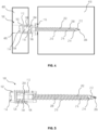
FIG. 4 shows a schematic illustration of a frame fastener in use to secure a frame to a wall. -
FIG. 5 shows a side view of a frame fastener, with a portion of the sleeve removed to show the inside of the sleeve. -
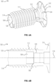
FIG. 6A shows a perspective view of a sleeve of a frame fastener according to another example. -
FIG. 6B shows a side section view of the sleeve ofFIG. 6A . -
FIG. 7A shows a perspective view of a screw of a frame fastener according to another example. -
FIG. 7B shows a side section view of the screw ofFIG. 7A , showing the side of the screw including the head. -
FIG. 8A shows a perspective view of a frame fastener including the sleeve ofFIG. 6 , and the screw ofFIG. 7 . -
FIG. 8B shows a side section view of the frame fastener ofFIG. 8A . - Certain terminology is used in the following description for convenience only and is not limiting. The words 'right', 'left', 'lower', 'upper', 'front', 'rear', 'upward', 'down' and 'downward' designate directions in the drawings to which reference is made and are with respect to the described component when assembled and mounted. The words `inner', `inwardly', `outer' and 'outwardly' refer to directions toward and away from, respectively, a designated centreline or a geometric centre of an element being described (e.g. central axis), the particular meaning being readily apparent from the context of the description.
- Further, as used herein, the terms 'connected', 'attached', 'coupled' and 'mounted' are intended to include direct connections between two members without any other members interposed therebetween, as well as, indirect connections between members in which one or more other members are interposed therebetween. The terminology includes the words specifically mentioned above, derivatives thereof, and words of similar import.
- Further, unless otherwise specified, the use of ordinal adjectives, such as, "first", "second" and "third" etc. merely indicate that different instances of like objects are being referred to and are not intended to imply that the objects so described must be in a given sequence, either temporally, spatially, in ranking or in any other manner.
- Like reference numerals are used to depict like features throughout.
- Referring now to
FIG. 1 , there is shown asleeve 102. Thesleeve 102 includes a through-channel 104, ascrew abutment surface 106, and a threadedouter surface 112. The through-channel 104 is an opening that extends through the length of thesleeve 102. Thescrew abutment surface 106 is provided within the through-channel 104, partitioning the through-channel 104 into two regions having different diameters. In particular, thescrew abutment surface 106 is provided as a stepped surface between afirst channel region 108 and asecond channel region 110. Thefirst channel region 108 is larger in diameter (i.e. wider) than thesecond channel region 110. The threadedouter surface 112 is provided on an external outer surface of thesleeve 102. A proximal end of thesleeve 102 is provided with a tool-engagingportion 114. The tool-engagingportion 114 may include an internal hex socket for engaging a hex key. In this example, the tool-engagingportion 114 may additionally or alternatively include castellations for engaging a tip of a screwdriver. A distal end of thesleeve 102 is provided with astopper flange 116 having a diameter which is larger than the diameter of the threadedouter surface 112. It is envisaged that the tool-engagingportion 114 may be internal of thesleeve 102 and/or external of thesleeve 102. It is also envisaged that tool-engagingportions 114 may be included at both ends of thesleeve 102. One of the tool-engagingportions 114 may be internal, and another of the tool-engagingportions 114 may be external. Any of the tool-engagingportions 114 may be used to engage and screw thesleeve 102, for example using a hex key or a screwdriver. -
FIG. 2 shows ascrew 202. Thescrew 202 has ahead 204 arranged at a proximal end and atip 206 arranged at a distal end. Thehead 204 of thescrew 202 is provided with a recessedsurface 218 for engagement of a screwdriver or tool. In other examples thehead 204 of thescrew 202 may include a different form of tool engaging socket or external shape, for example a hexagonal profile for a socket tool. Extending between thehead 204 and thetip 206 is ashaft 208. Theshaft 208 includes ahardened cutting thread 210. Thehardened cutting thread 210 includes a plurality of threads that are hardened, for example by a heat treatment process. Thehardened cutting thread 210 may be formed by a thread rolling process followed by heat treatment. The whole screw may be hardened to provide the hardened cutting thread, or the whole screw may be hardened to a first degree and the hardened cutting thread may be hardened to a greater degree. In this example, thehardened cutting thread 210 extends over a taperedportion 212 of thetip 206. Thehardened cutting thread 210 includes a plurality ofnotches 216 that trap and compress dust when screwing into masonry to increase fixation. Thenotches 216 are linearly spaced from each other along adjacent turns of the thread. In this example, thescrew 202 is made of steel, in particular stainless steel. In this particle example, the core hardness of thescrew 202 is 450HV5 (Vickers hardness number of 450 at a load of 5kgf). Also, in this particular example, the surface hardness of thehardened cutting thread 210 is 700HV03 (Vickers hardness number of 700 at a load of 0.3kgf). Having a cutting thread with a hardened surface is particularly beneficial for screwing into harder materials such as masonry because it has a high resistance to wear. - The
tip 206 of thescrew 202 has a taperedportion 212 provided with a cuttingthread 214. The taperedportion 212 is tapered in shape from theshaft 208 to thetip 206 of thescrew 202. The cuttingthread 214 spans the length of the taperedportion 212. In this example, the cuttingthread 214 extends over a portion of theshaft 208 of thescrew 202. Thescrew 202 has acylindrical part 222 which is arranged between thehead 204 and theshaft 208, and ashank 220 which is arranged between thecylindrical part 222 and theshaft 208. - The thread angle of the cutting
thread 214 is less than the thread angle of thehardened cutting thread 210, each thread angle being measured with respect to a longitudinal axis of thescrew 202. The thread angle of the cuttingthread 214 is adapted for wood fibre splitting. The thread angle of the of thehardened cutting thread 210 is adapted to screw into masonry and also into wood after splitting of the wood fibres. The thread angle of the cuttingthread 214 may be in the range of 5 degrees to 45 degrees. Other ranges of thread angle of the cuttingthread 214 are envisaged, for example: 10 to 35 degrees; 15 to 30 degrees; 15 to 20 degrees; and 16 to 18 degrees. In this particular example, the thread angle of the cuttingthread 214 is 17 degrees. The thread angle of thehardened cutting thread 210 may be in the range of 45 degrees to 85 degrees. Other ranges of the thread angle of thehardened cutting thread 210 are envisaged, for example: 55 to 85 degrees; 60 to 80 degrees; 70 to 80 degrees; and 72 to 78 degrees. In this particular example, the thread angle of thehardened cutting thread 210 is 75 degrees. Other thread angles of the cuttingthread 214 andhardened cutting thread 210 are envisaged. -
FIG. 3A and FIG. 3B show aframe fastener 100 which includes thesleeve 102 and screw 202 as previously described. As best seen inFIG. 3B , when assembled, thescrew 202 is inserted into the through-channel 104 of thesleeve 102 in a direction from the proximal end (i.e. tool-engagingportion 114 side) to the distal end (i.e.stopper flange 116 side). Thehead 204 of thescrew 202 is sized such that it abuts thescrew abutment surface 106 of thesleeve 102 upon insertion of thescrew 202 into thesleeve 102. Thescrew abutment surface 106 limits the movement of thescrew 202 in the axial direction. When thehead 204 of thescrew 202 abuts against thescrew abutment surface 106, thecylindrical part 222 of thescrew 202 is received in thesecond channel region 110 of the through-channel 104, which increases the engagement and the axial alignment of thescrew 202 with thesleeve 102 and, in turn, improves the structural rigidity and stability of theframe fastener 100. In this example, thecylindrical part 222 of thescrew 202 has an axial length that corresponds with the axial length of thesecond channel region 110. - The use of the
frame fastener 100 will now be described with reference toFIG. 4 . Theframe fastener 100 is used to secure aframe 400 to awall 410. In this example, theframe 400 is a window frame. However, other frames are envisaged, for example theframe 400 may be a door frame. - In use, to secure a
frame 400 to an opening in awall 410, ahole 405 is drilled into theframe 400, and thesleeve 102 is inserted into thehole 405 from the outside (wall 410 side) before theframe 400 is placed into the opening of thewall 410. Thesleeve 102 is screwed all the way into theframe 400 until thestopper flange 116 abuts the surface of theframe 400. Theframe 400, with thesleeve 102 inserted inside, is positioned in thewall 410 opening. Thesleeve 102 is then unscrewed from the inside until thestopper flange 116 abuts the surface of thewall 410. This holds theframe 400 in place relative to thewall 410. This process is repeated to secure theframe 400 to thewall 410 at different locations, and a check can be made to ensure that theframe 400 is level with thewall 410 and properly positioned. Once theframe 400 is positioned properly, thescrew 202 is inserted through thehole 405 in theframe 400 and through thesleeve 102 into thewall 410, to secure theframe fastener 100 together. An adjustment in the distance between theframe 400 and thewall 410 can later be made by loosening thescrew 202, rotating thesleeve 102 in a direction depending on whether thesleeve 102 needs to be tightened or loosened, and then retightening thescrew 202. - The
frame fastener 100, in particular thescrew 202, can be used with different types of materials, for example softer materials such as wood, and harder materials such as masonry. Accordingly, thesame frame fastener 100 can be used for openings with wood and/or masonry openings. - The
screw 202 may be inserted into awall 410 made of a softer material such as wood. The cuttingthread 214 provided on the taperedportion 212 of thetip 206 cuts into thewall 410 to create an opening for inserting theframe fastener 100. As thescrew 202 of theframe fastener 100 is inserted further, thehardened cutting thread 210 of thescrew 202 engages with the edge of the opening in thewall 410 to secure thescrew 202 to thewall 410. In examples where thewall 410 is made of wood, the cuttingthread 214 may split the wood fibres in thewall 410 and thehardened cutting thread 210 can screw into the wood to secure it. - The
screw 202 may be inserted into awall 410 made of a harder material such as concrete or other masonry. Thewall 410 may include a pilot (i.e. pre-drilled) hole. The pilot hole may have a maximum diameter which is less than the diameter of the cuttingthread 214. When thescrew 202 is inserted into thewall 410, thetip 206 enters thewall 410 without contacting the edge of the pilot hole. When theshaft 208 of thescrew 202 is inserted into thewall 410, thehardened cutting thread 210 engages with the edge of the pilot hole, to secure thescrew 202 with thewall 410. - Therefore, the
frame fastener 100 can be inserted both into walls made of a softer material such as wood, and made of a harder material such as masonry. Theframe fastener 100 is multi-purpose and suitable for different types of materials, removing the need to use different frame fasteners each only suitable for a single material or type of material. -
FIG. 5 shows an example of aframe fastener 100 with asleeve 102 that is modified from the example previously described. The other aspects of theframe fastener 100 are the same so will not be described again here. In this example, instead of a singlescrew abutment surface 106, the through-channel 104 of thesleeve 102 is provided with two screw abutment surfaces 106, 124. In this way, the two screw abutment surfaces 106, 124 limit the movement of thescrew 202 within thesleeve 102. This traps thescrew 202 within a predetermined region within thesleeve 102 defined by the two screw abutment surfaces 106, 124 of the through-channel 104. Thescrew 202 can freely rotate within thesleeve 102. The secondscrew abutment surface 124 may be a stepped surface towards the tool-engagingportion 114. Each of the screw abutment surfaces 106, 124 may be a stepped surface. - In use, the
frame fastener 100 including both thesleeve 102 and thescrew 202 is inserted into thehole 405 of theframe 400 and into thewall 410 from the inside. Thescrew 202 is screwed into thewall 410 while thesleeve 102 is rotated at the same time to screw into theframe 400, for example using a tool that simultaneously engages a hex socket in thesleeve 102 and a recessedsurface 218 in thescrew 202. To adjust the spacing between theframe 400 and thewall 410, thesleeve 102 can be screwed to be tightened or loosened, for example using a hex key to rotate thesleeve 102 independently from thescrew 202. This moves thesleeve 102 relative to thescrew 202, and therefore moves theframe 400 towards and away from thewall 410. -
FIG. 6A and FIG. 6B show another example of asleeve 502 including a through-channel 504 defining acentral axis 518, ascrew abutment surface 506, and a threadedouter surface 512. The through-channel 504 is an opening that extends through the length of thesleeve 502 between a head of thesleeve 502 and an opposite tip. Unlike thesleeve 102 described inFIG. 1 , the through-channel 504 includes a slopedportion 520 that is angled relative to thecentral axis 518. - In this example, the angle formed between the
sloped portion 520 andcentral axis 518 is 1.75 degrees, although other angles are envisaged, for example between 0 (excluded) and 10 (included) degrees, between 1 and 2 degrees (included), or between 1.5 and 2 degrees (included). The slopedportion 520 is arranged adjacent thescrew abutment surface 506 along thecentral axis 518, in particular in a direction towards a head of thesleeve 502. The slopedportion 520 tapers inwards in a direction from the tip to the head of thesleeve 502. In this example, the slopedportion 520 has a frustoconical shape. In this example, the slopedportion 520 spans an axial length, along thecentral axis 518, of between 2.5 and 12mm (included), or between 4 and 8mm (included). - The threaded
outer surface 512 is provided on an external outer surface of thesleeve 502. A proximal end (i.e. tip) of thesleeve 502 is provided with a tool-engagingportion 514. The proximal end of thesleeve 502 is also provided with cuttingtips 530 which help thesleeve 502 cut into an installation hole. A distal end (i.e. head) of thesleeve 502 is provided with astopper flange 516 having a diameter which is larger than the diameter of the threadedouter surface 512. The perimeter of thestopper flange 516 is provided withcircumferential teeth 532 andradial ribs 534 that facilitate a flush installation and reduce splitting. Thecircumferential teeth 532 andradial ribs 534 extend or protrude axially from thestopper flange 516 towards the tip ofsleeve 502. Thecircumferential teeth 532 may have a sharp tip. Theradial ribs 534 may have a sharp radial edge. Arranged between thestopper flange 516 and the threadedouter surface 512 is a number ofreinforcement ribs 522 improve the strength and stiffness of thesleeve 502. Thereinforcement ribs 522 extend or protrude radially from a tubular wall arranged between thestopper flange 516 and the threadedouter surface 512. In this example, thereinforcement ribs 522 extend externally from the tubular wall although they could extend internally from the tubular wall. Thereinforcement ribs 522 makes it possible to save material without compromising the strength of thesleeve 502. -
FIG. 7A and FIG. 7B show another example of ascrew 602 having atip 606,shaft 608, hardenedcutting thread 610, taperedportion 612, cuttingthread 614,notches 616, recessedsurface 618,shank 620 that are the same as that of thescrew 202 inFIG. 2 . Thescrew 602 has a head and atip 606 at opposite ends, and ashaft 608 extending between the head and thetip 606. The head in this example includes aflange 604 and ahead portion 624 extending from theflange 604 in a direction towards thetip 606. InFIG. 7A and FIG. 7B , thecylindrical part 222 of the screw ofFIG. 2 is replaced by ahead portion 624 having a slopedprofile 626. Thesloped profile 626 tapers inwards in a direction from the head to thetip 606 of thescrew 602. In this example, the angle formed between thesloped profile 626 and acentral axis 628 of thescrew 602 is 1.75 degrees, although other angles are envisaged, for example between 0 (excluded) and 10 (included) degrees, between 1 and 2 degrees (included), or between 1.5 and 2 degrees (included). Thehead portion 624 in this example has a frustoconical shape 630. -
FIG. 8A and FIG. 8B show aframe fastener 500 including thesleeve 502 ofFIG. 7 and thescrew 602 ofFIG. 8 . During assembly, thescrew 602 is inserted into the through-channel 504 of thesleeve 502 from the proximal end having the tool-engagingportion 514 towards the distal end having thestopper flange 516. Thehead portion 624 of thescrew 602 enters the slopedportion 520 of thescrew 602, causing the movement of thescrew 602 to be limited in the axial direction, and to further improve contact and axial alignment of thescrew 602 within thesleeve 502. This is particularly beneficial because the increased contact area between thesleeve 502 and thescrew 602 reduces vibrations and relative movement therebetween. It also improves the transfer of forces between thesleeve 502 and thescrew 602, improving pull-out resistance, strength and stability. The sloped contact is provided directly between thesleeve 502 and thescrew 602, meaning that no additional components are required for centering thescrew 602. It is envisaged that thesleeve 502 may include a screw abutment surface 506 (seeFIG. 6B ) to further restrict the movement of thescrew 602. It is to be appreciated that the screw abutment surface could be formed by a step for abutting the flange of thescrew 602 head, or thehead portion 624 could abut against the slopedportion 520 for thesleeve 502 to engage thescrew 602. Thesleeve 502 is further strengthened by thereinforcement ribs 522 provided between the threadedouter surface 512 and thestopper flange 516. Thecircumferential teeth 532 andradial ribs 534 provided on thestopper flange 516 facilitate a flush installation into the surface to be installed and reduce splitting. - It will be appreciated by persons skilled in the art that the above detailed examples have been described by way of example only and not in any limitative sense, and that various alterations and modifications are possible without departing from the scope of the invention as defined by the appended claims. Various modifications to the detailed examples described above are possible.
- Through the description and claims of this specification, the words "comprise" and "contain" and variations of them mean "including but not limited to", and they are not intended to (and do not) exclude other moieties, additives, components, integers or steps. Throughout the description and claims of this specification, the singular encompasses the plural unless the context otherwise requires. In particular, where the indefinite article is used, the specification is to be understood as contemplating plurality as well as singularity, unless the context requires otherwise.
- Features, integers, characteristics, compounds, chemical moieties or groups described in conjunction with a particular aspect, embodiment or example of the invention are to be understood to be applicable to any other aspect, embodiment or example described herein unless incompatible therewith. All of the features disclosed in this specification (including any accompanying claims, abstract and drawings), and/or all of the steps of any method or process so disclosed, may be combined in any combination, except combinations where at least some of such features and/or steps are mutually exclusive. The invention is not restricted to the details of any foregoing embodiments. The invention extends to any novel one, or any novel combination, of the features disclosed in this specification (including any accompanying claims, abstract or drawings), or to any novel one, or any novel combination, of the steps of any method or process so disclosed.
- It will be appreciated by persons skilled in the art that the above embodiment(s) have been described by way of example only and not in any limitative sense, and that various alterations and modifications are possible without departing from the scope of the invention as defined by the appended claims. Various modifications to the detailed designs as described above are possible.
Claims (15)
- A sleeve for receiving a screw to secure a frame, for example a window frame or a door frame, to a wall, comprising:a threaded outer surface configured to screw into the frame; anda through-channel defining a central axis of the sleeve, comprising a sloped portion that is angled relative to the central axis for central alignment of a screw when the screw is inserted into the through-channel of the sleeve.
- A sleeve according to claim 1, wherein the sloped portion of the through-channel is arranged in direct contact with the screw.
- A sleeve according to claim 2, wherein the sloped portion of the through-channel is arranged in direct contact with a head portion of the screw.
- A sleeve according to any preceding claim, wherein the through-channel comprises a screw abutment surface that comprises a step for abutting a head flange of the screw.
- A sleeve according to any preceding claim, wherein the through-channel comprises a screw abutment surface, and wherein the sloped portion is arranged adjacent the screw abutment surface along the central axis of the sleeve.
- A sleeve according to claim 5, wherein the sloped portion is adjacent the screw abutment surface in a direction towards a head of the sleeve.
- A sleeve according to any preceding claim, wherein the sloped portion has a frustoconical shape.
- A sleeve according any preceding claim, wherein the sloped portion tapers inwards in a direction from a tip to a head of the sleeve.
- A sleeve according to any preceding claim, wherein the sloped portion forms an angle relative to the central axis that is between 0 and 10 degrees, optionally between 1 and 2 degrees, and further optionally between 1.5 and 2 degrees.
- A sleeve according to any preceding claim, wherein the sloped portion spans an axial length, along the central axis, of between 2.5 and 12 millimetres, and optionally between 4 and 8 millimetres.
- A sleeve according to any preceding claim, further comprising a head and an opposite tip, wherein the head comprises a stopper flange with circumferential teeth and/or radial ribs extending towards the tip.
- A sleeve according to any preceding claim, further comprising a stopper flange and reinforcements ribs arranged between the stopper flange and the threaded outer surface.
- A frame fastener for securing a frame, for example a window frame or a door frame, to a wall, comprising:a sleeve comprising a threaded outer surface configured to screw into the frame, and a through-channel defining a central axis of the sleeve, the through-channel comprising a sloped portion that is angled relative to the central axis; anda screw having a head and a tip at opposite ends, and a shaft extending between the head and the tip, wherein the screw is sized and shaped to abut the sloped portion such that screw extends through the through-channel in alignment with the central axis.
- A frame fastener according to claim 11, wherein the sloped portion of the through-channel and the screw are in direct contact, and preferably wherein the sloped portion of the through-channel and a head portion of the screw are in direct contact.
- A frame fastener according to claim 13, wherein the head portion of the screw comprises a sloped profile, and preferably wherein the sloped profile has a frustoconical shape, and more preferably wherein the sloped profile tapers inwards in a direction from the head to the tip of the screw.
Applications Claiming Priority (1)
| Application Number | Priority Date | Filing Date | Title |
|---|---|---|---|
| EP23198246.3A EP4528059A1 (en) | 2023-09-19 | 2023-09-19 | Frame fastener |
Publications (1)
| Publication Number | Publication Date |
|---|---|
| EP4528116A1 true EP4528116A1 (en) | 2025-03-26 |
Family
ID=88097571
Family Applications (2)
| Application Number | Title | Priority Date | Filing Date |
|---|---|---|---|
| EP23198246.3A Pending EP4528059A1 (en) | 2023-09-19 | 2023-09-19 | Frame fastener |
| EP24200899.3A Pending EP4528116A1 (en) | 2023-09-19 | 2024-09-17 | Sleeve and frame fastener |
Family Applications Before (1)
| Application Number | Title | Priority Date | Filing Date |
|---|---|---|---|
| EP23198246.3A Pending EP4528059A1 (en) | 2023-09-19 | 2023-09-19 | Frame fastener |
Country Status (1)
| Country | Link |
|---|---|
| EP (2) | EP4528059A1 (en) |
Citations (5)
| Publication number | Priority date | Publication date | Assignee | Title |
|---|---|---|---|---|
| US4486134A (en) * | 1982-05-17 | 1984-12-04 | White Timothy T | Adjustable connector assembly |
| EP0272020A1 (en) * | 1986-12-10 | 1988-06-22 | Harry Francis Cole | An insert for providing a screw-threaded hole in an object |
| US20080226420A1 (en) * | 2007-03-12 | 2008-09-18 | Joker Industrial Co., Ltd. | Adjusting screw for door frames and window casings |
| US20090317209A1 (en) * | 2006-09-06 | 2009-12-24 | Klaus Friedrich Grubert | Method For Mounting A Screw And A Thread-Armoring Element, And Arrangement For Carrying Out Said Method |
| EP2029847B1 (en) * | 2006-06-12 | 2015-12-23 | Jeld-Wen Sverige AB | Fastener for fixing a door or window frame to the border of an opening in a building |
Family Cites Families (4)
| Publication number | Priority date | Publication date | Assignee | Title |
|---|---|---|---|---|
| DE29611749U1 (en) * | 1996-07-05 | 1996-09-05 | Berner GmbH, 74653 Künzelsau | Spacer screw |
| NO304997B1 (en) * | 1997-06-11 | 1999-03-15 | Igela As | Screw sleeve and support plate for adjustable attachment of a structural part to a support |
| DE202008011808U1 (en) * | 2008-09-05 | 2008-12-24 | M-Cut Systems Gmbh & Co. Kg | Thread forming screw |
| SE539536C2 (en) * | 2014-11-20 | 2017-10-10 | Essve Produkter Ab | Frame screw |
-
2023
- 2023-09-19 EP EP23198246.3A patent/EP4528059A1/en active Pending
-
2024
- 2024-09-17 EP EP24200899.3A patent/EP4528116A1/en active Pending
Patent Citations (5)
| Publication number | Priority date | Publication date | Assignee | Title |
|---|---|---|---|---|
| US4486134A (en) * | 1982-05-17 | 1984-12-04 | White Timothy T | Adjustable connector assembly |
| EP0272020A1 (en) * | 1986-12-10 | 1988-06-22 | Harry Francis Cole | An insert for providing a screw-threaded hole in an object |
| EP2029847B1 (en) * | 2006-06-12 | 2015-12-23 | Jeld-Wen Sverige AB | Fastener for fixing a door or window frame to the border of an opening in a building |
| US20090317209A1 (en) * | 2006-09-06 | 2009-12-24 | Klaus Friedrich Grubert | Method For Mounting A Screw And A Thread-Armoring Element, And Arrangement For Carrying Out Said Method |
| US20080226420A1 (en) * | 2007-03-12 | 2008-09-18 | Joker Industrial Co., Ltd. | Adjusting screw for door frames and window casings |
Also Published As
| Publication number | Publication date |
|---|---|
| EP4528059A1 (en) | 2025-03-26 |
Similar Documents
| Publication | Publication Date | Title |
|---|---|---|
| EP1000253B1 (en) | Improved fixing anchor | |
| US6050765A (en) | Fastener for logs and fastening technique therefor | |
| US7147419B2 (en) | Element of fastening accessories to metal windows and doors | |
| US6250866B1 (en) | Self-drilling, self-tapping screw for concrete blocks | |
| JP2520164B2 (en) | Expansion and buckling plugs made of plastic material | |
| US5816012A (en) | Dual threaded fastener and metal component assembly | |
| US20100278614A1 (en) | Fixing device | |
| DK2366843T3 (en) | A device for fixation of the insulation material | |
| EP2687735A1 (en) | Masonry screws | |
| TW201632743A (en) | Screw having discontinuity on middle threaded section | |
| WO2011117612A1 (en) | Fixing element | |
| EP0560789B1 (en) | Improved fixing | |
| EP4528059A1 (en) | Frame fastener | |
| CN100424317C (en) | Device for fastening fittings to multi-chamber profiles | |
| WO2002012736A1 (en) | Screw for concrete and masonry | |
| NZ549785A (en) | Method of fixing a bolt where rotating the bolt expands a section by engaging a head that does not rotate | |
| CA2478989C (en) | Fixing device and method for fixing to a substrate | |
| US20240209889A1 (en) | Wood screw | |
| JP2025526282A (en) | A container, preferably a drawer | |
| WO2025027650A1 (en) | A threaded insert for machine screwing | |
| AU2001278303A1 (en) | Screw for concrete and masonry | |
| GB2424460A (en) | Expanding fastener | |
| HK1000383A1 (en) | Improved fixing | |
| HK1072970B (en) | Fixing device and method for fixing to a substrate |
Legal Events
| Date | Code | Title | Description |
|---|---|---|---|
| PUAI | Public reference made under article 153(3) epc to a published international application that has entered the european phase |
Free format text: ORIGINAL CODE: 0009012 |
|
| STAA | Information on the status of an ep patent application or granted ep patent |
Free format text: STATUS: THE APPLICATION HAS BEEN PUBLISHED |
|
| AK | Designated contracting states |
Kind code of ref document: A1 Designated state(s): AL AT BE BG CH CY CZ DE DK EE ES FI FR GB GR HR HU IE IS IT LI LT LU LV MC ME MK MT NL NO PL PT RO RS SE SI SK SM TR |
|
| STAA | Information on the status of an ep patent application or granted ep patent |
Free format text: STATUS: REQUEST FOR EXAMINATION WAS MADE |
|
| 17P | Request for examination filed |
Effective date: 20250924 |
|
| RIN1 | Information on inventor provided before grant (corrected) |
Inventor name: FRIIS, MORTEN Inventor name: NISSEN, ANDERS |