EP4528110A1 - Method for detecting and annunciating gas turbine engine compressor stall - Google Patents
Method for detecting and annunciating gas turbine engine compressor stall Download PDFInfo
- Publication number
- EP4528110A1 EP4528110A1 EP24202011.3A EP24202011A EP4528110A1 EP 4528110 A1 EP4528110 A1 EP 4528110A1 EP 24202011 A EP24202011 A EP 24202011A EP 4528110 A1 EP4528110 A1 EP 4528110A1
- Authority
- EP
- European Patent Office
- Prior art keywords
- speed
- pilot
- compressor
- corrective action
- set forth
- Prior art date
- Legal status (The legal status is an assumption and is not a legal conclusion. Google has not performed a legal analysis and makes no representation as to the accuracy of the status listed.)
- Pending
Links
Images


Classifications
-
- F—MECHANICAL ENGINEERING; LIGHTING; HEATING; WEAPONS; BLASTING
- F02—COMBUSTION ENGINES; HOT-GAS OR COMBUSTION-PRODUCT ENGINE PLANTS
- F02C—GAS-TURBINE PLANTS; AIR INTAKES FOR JET-PROPULSION PLANTS; CONTROLLING FUEL SUPPLY IN AIR-BREATHING JET-PROPULSION PLANTS
- F02C9/00—Controlling gas-turbine plants; Controlling fuel supply in air- breathing jet-propulsion plants
- F02C9/26—Control of fuel supply
- F02C9/32—Control of fuel supply characterised by throttling of fuel
-
- F—MECHANICAL ENGINEERING; LIGHTING; HEATING; WEAPONS; BLASTING
- F02—COMBUSTION ENGINES; HOT-GAS OR COMBUSTION-PRODUCT ENGINE PLANTS
- F02C—GAS-TURBINE PLANTS; AIR INTAKES FOR JET-PROPULSION PLANTS; CONTROLLING FUEL SUPPLY IN AIR-BREATHING JET-PROPULSION PLANTS
- F02C7/00—Features, components parts, details or accessories, not provided for in, or of interest apart form groups F02C1/00 - F02C6/00; Air intakes for jet-propulsion plants
- F02C7/26—Starting; Ignition
- F02C7/262—Restarting after flame-out
-
- F—MECHANICAL ENGINEERING; LIGHTING; HEATING; WEAPONS; BLASTING
- F02—COMBUSTION ENGINES; HOT-GAS OR COMBUSTION-PRODUCT ENGINE PLANTS
- F02C—GAS-TURBINE PLANTS; AIR INTAKES FOR JET-PROPULSION PLANTS; CONTROLLING FUEL SUPPLY IN AIR-BREATHING JET-PROPULSION PLANTS
- F02C9/00—Controlling gas-turbine plants; Controlling fuel supply in air- breathing jet-propulsion plants
- F02C9/16—Control of working fluid flow
- F02C9/18—Control of working fluid flow by bleeding, bypassing or acting on variable working fluid interconnections between turbines or compressors or their stages
-
- F—MECHANICAL ENGINEERING; LIGHTING; HEATING; WEAPONS; BLASTING
- F02—COMBUSTION ENGINES; HOT-GAS OR COMBUSTION-PRODUCT ENGINE PLANTS
- F02C—GAS-TURBINE PLANTS; AIR INTAKES FOR JET-PROPULSION PLANTS; CONTROLLING FUEL SUPPLY IN AIR-BREATHING JET-PROPULSION PLANTS
- F02C9/00—Controlling gas-turbine plants; Controlling fuel supply in air- breathing jet-propulsion plants
- F02C9/26—Control of fuel supply
- F02C9/28—Regulating systems responsive to plant or ambient parameters, e.g. temperature, pressure, rotor speed
-
- F—MECHANICAL ENGINEERING; LIGHTING; HEATING; WEAPONS; BLASTING
- F04—POSITIVE - DISPLACEMENT MACHINES FOR LIQUIDS; PUMPS FOR LIQUIDS OR ELASTIC FLUIDS
- F04D—NON-POSITIVE-DISPLACEMENT PUMPS
- F04D27/00—Control, e.g. regulation, of pumps, pumping installations or pumping systems specially adapted for elastic fluids
- F04D27/001—Testing thereof; Determination or simulation of flow characteristics; Stall or surge detection, e.g. condition monitoring
-
- F—MECHANICAL ENGINEERING; LIGHTING; HEATING; WEAPONS; BLASTING
- F02—COMBUSTION ENGINES; HOT-GAS OR COMBUSTION-PRODUCT ENGINE PLANTS
- F02C—GAS-TURBINE PLANTS; AIR INTAKES FOR JET-PROPULSION PLANTS; CONTROLLING FUEL SUPPLY IN AIR-BREATHING JET-PROPULSION PLANTS
- F02C9/00—Controlling gas-turbine plants; Controlling fuel supply in air- breathing jet-propulsion plants
- F02C9/16—Control of working fluid flow
- F02C9/20—Control of working fluid flow by throttling; by adjusting vanes
-
- F—MECHANICAL ENGINEERING; LIGHTING; HEATING; WEAPONS; BLASTING
- F05—INDEXING SCHEMES RELATING TO ENGINES OR PUMPS IN VARIOUS SUBCLASSES OF CLASSES F01-F04
- F05D—INDEXING SCHEME FOR ASPECTS RELATING TO NON-POSITIVE-DISPLACEMENT MACHINES OR ENGINES, GAS-TURBINES OR JET-PROPULSION PLANTS
- F05D2260/00—Function
- F05D2260/80—Diagnostics
-
- F—MECHANICAL ENGINEERING; LIGHTING; HEATING; WEAPONS; BLASTING
- F05—INDEXING SCHEMES RELATING TO ENGINES OR PUMPS IN VARIOUS SUBCLASSES OF CLASSES F01-F04
- F05D—INDEXING SCHEME FOR ASPECTS RELATING TO NON-POSITIVE-DISPLACEMENT MACHINES OR ENGINES, GAS-TURBINES OR JET-PROPULSION PLANTS
- F05D2270/00—Control
- F05D2270/01—Purpose of the control system
- F05D2270/09—Purpose of the control system to cope with emergencies
- F05D2270/092—Purpose of the control system to cope with emergencies in particular blow-out and relight
-
- F—MECHANICAL ENGINEERING; LIGHTING; HEATING; WEAPONS; BLASTING
- F05—INDEXING SCHEMES RELATING TO ENGINES OR PUMPS IN VARIOUS SUBCLASSES OF CLASSES F01-F04
- F05D—INDEXING SCHEME FOR ASPECTS RELATING TO NON-POSITIVE-DISPLACEMENT MACHINES OR ENGINES, GAS-TURBINES OR JET-PROPULSION PLANTS
- F05D2270/00—Control
- F05D2270/01—Purpose of the control system
- F05D2270/10—Purpose of the control system to cope with, or avoid, compressor flow instabilities
- F05D2270/101—Compressor surge or stall
-
- F—MECHANICAL ENGINEERING; LIGHTING; HEATING; WEAPONS; BLASTING
- F05—INDEXING SCHEMES RELATING TO ENGINES OR PUMPS IN VARIOUS SUBCLASSES OF CLASSES F01-F04
- F05D—INDEXING SCHEME FOR ASPECTS RELATING TO NON-POSITIVE-DISPLACEMENT MACHINES OR ENGINES, GAS-TURBINES OR JET-PROPULSION PLANTS
- F05D2270/00—Control
- F05D2270/30—Control parameters, e.g. input parameters
- F05D2270/304—Spool rotational speed
Definitions
- This relates to a method and apparatus for detecting stall conditions in the compressor of a gas turbine engine.
- Gas turbine engines typically include a propulsor, such as a fan delivering air into a compressor.
- the air is compressed in the compressor and delivered into a combustor.
- Products of the combustion pass downstream over turbine rotors driving them to rotate.
- the turbine rotors in turn drive compressor and fan rotors.
- a gas turbine engine that includes a propulsor, a compressor and a turbine section having a first turbine rotor connected to the compressor through a first shaft.
- a second turbine rotor is connected to at least the propulsor through a second shaft.
- the first turbine rotor drives the compressor at a first speed
- the second turbine rotor drives the propulsor at a second speed.
- the control also is programmed to identify a flame out condition, and identify a locked in stall condition when the difference between the two speeds exceeds a threshold for at least a threshold period of time at least in part concurrently with the flame out condition.
- the control is programmed to take a corrective action should the locked in stall condition be identified.
- a method of operating a gas turbine engine including operating a propulsor, a compressor and a turbine section having a first turbine rotor driving the compressor.
- a second turbine rotor drives at least the propulsor.
- the first turbine rotor drives the compressor through a first shaft at a first speed.
- the second turbine rotor drives the propulsor through a second shaft at a second speed.
- One of the first speed and the second speed is compared to a commanded first or second speed and determines a difference and identifies a flame out condition.
- a locked in stall condition is identified if the difference between the two speeds exceeds a threshold for at least a threshold period of time at least in part concurrently with the flame out condition.
- a corrective action is taken should the locked in stall condition be identified.
- FIG. 1 schematically illustrates a gas turbine engine 20.
- the example gas turbine engine 20 is a turbofan that generally incorporates a fan section 22, a compressor section 24, a combustor section 26 and a turbine section 28.
- the fan section 22 drives air along a bypass flow path B in a bypass duct defined within a nacelle 30.
- the fan section 22 also delivers air along a core flow path C into the compressor section 24 for compression and into the combustor section 26.
- the compressed air is mixed with fuel from a fuel system 32 and ignited by igniter 34 to generate an exhaust gas flow that expands through the turbine section 28 and is exhausted through exhaust nozzle 36.
- turbofan turbine engine in the disclosed non-limiting embodiment, it should be understood that the concepts described herein are not limited to use with turbofans as the teachings may be applied to other types of turbine engines.
- the propulsor may be an open propeller (i.e. turboprop), or a turboj et, turboshaft or Auxiliary Power Unit (APU).
- APU Auxiliary Power Unit
- the engine 20 is shown to have a high speed turbine rotor 40 driving a high speed shaft 42 to in turn drive a compressor rotor 44.
- a low speed turbine 46 drives a low speed shaft 48 to in turn drive the fan 22.
- the high speed turbine 40, shaft 42, and compressor 44 can be referred to as a high speed spool.
- the high speed spool rotational speed is typically known as N2.
- the low speed turbine 46, shaft 48 and fan rotor 22 are known as a low speed spool.
- the low speed spool rotational speed is typically known as N1. While low speed spool is only shown driving the fan rotor, gas turbine engines may also have the low speed spool driving a low speed compressor.
- a de-icing system 50 for the nacelle 30 is shown schematically. As known, compressed air is tapped from the compressor 44 and delivered into the nacelle 30 for de-icing purposes. This system may be as known.
- a controller 49 typically known as a full authority digital electronic controller (“FADEC”) is shown controlling the engine.
- the FADEC 49 also communicates with a warning system 51 in a cockpit of an associated aircraft, shown schematically as box 53.
- Figure 2 is a graph of several variables across a period of time.
- a flameout indication usually occurs where the FADEC turns on the flameout flag. If the flameout flag is not available on the data stream however then a substitute may be used which coincides with the flameout flag such as the ignitor flag.
- the flameout flag or an equivalent indicator in this case the ignitor flag
- any other flag based on a drop in N1/N2 compressor discharge pressure, engine power or thrust, may be interpreted as a flameout indicator.
- the equivalent indicator could be any indication of a loss of power/speed indicator.
- any of these can be taken as identifying a flame out condition.
- N1 COMMANDED There are three speed lines N1 COMMANDED, which is a commanded N1 speed, N2 and N1 actual. At point V there is a large difference between N1 actual and N1 Commanded. This would also be indicative of a locked in stall condition.
- the FADEC 49 will make a determination that a locked in stall condition is occurring, and take proactive action.
- the flame out condition flag 54 also is preferably found to be within a maximum period of time from the location V where the speed difference is determined. As an example, the maximum period of time may be within thirty seconds. Further, the FADEC will also be programmed to avoid false positives by checking to make sure the engine starting and engine shutdown parameters are not occurring, or are false.
- the FADEC 49 can send a warning signal to system 51 that a locked in stall condition is occurring.
- the pilot would then know to take the corrective action of reducing the throttle position, which in turn would reduce fuel flow and/or open the engine Bleed Off Valves (BOVs). This is shown at point X.
- BOVs Bleed Off Valves
- Other corrective actions may include the FADEC 49 automatically reducing the fuel level to correct the locked in stall. Additionally, or as an alternative, the bleeding of compressor air into the anti-ice system 50, or overboard may occur which would help unload the compressor. This can also reduce or eliminate a locked in stall condition.
- Figure 2 also shows the engine Inter Turbine Temperature (ITT) rising with the locked in stall condition, and then dropping with the correction at point Z.
- ITT Inter Turbine Temperature
- Conditions that the FADEC 49 may utilize to determine a flame out condition would be a rate of change of N2 such that the N2 speed is dropping too quickly. It at may also involve a rapid drop in Compressor Exit Pressure.
- a compressor exit temperature may be looked at to determine a flame out condition. If Inter Turbine Temperature (ITT) and/or Exhaust Gas Temperature (EGT) is lower than would be expected this is indicative of a flame out condition.
- ITT Inter Turbine Temperature
- EHT Exhaust Gas Temperature
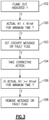
- FIG. 3 A flow chart of a method according to this disclosure is shown in Figure 3 .
- a FADEC asks whether a flame out is indicated. If yes, at step 100 the FADEC asks whether actual N1 is less than N1 COMMANDED by a predetermined amount for a minimum period of time. If the answer to steps 1 and 2 are both yes within a predetermined maximum time period, then at step 103 a cockpit message or fault flag is set.
- step 104 a corrective action is taken.
- step 106 the FADEC asks is actual N1 ⁇ N1 REF for a minimum time? If the answer is yes then at step 108 the message or fault flag is removed.
- N1 difference is specifically disclosed, a similar difference in any actual spool speed and their commanded spool speed can be used (example, N2 actual and N2 commanded).
- a gas turbine engine includes a propulsor 22, a compressor 24 and a turbine section 28 having a first turbine rotor 42 connecting to the compressor through a first shaft.
- a second turbine rotor 46 connects to at least the propulsor through a second shaft.
- the first turbine rotor drives the compressor at a first speed
- the second turbine rotor drives the propulsor at a second speed. It should be understood both turbine rotors may drive a single blade row or plural blade rows.
- a control 49 for the gas turbine engine is programmed to compare one of the first speed and the second speed to a commanded speed to determine a difference.
- the control also is programmed to identify a flame out condition, and identify a locked in stall condition when the difference between the two speeds exceeds a threshold for at least a threshold period of time at least in part concurrently with the flame out condition.
- the control is programmed to take a corrective action 51 should the locked in stall condition be identified.
- the first speed is utilized to compare to the commanded first speed.
- control is connected to communicate with a pilot warning device 51, and the corrective action is advising the pilot to take a corrective action.
- the corrective action is the pilot reducing a throttle position.
- the corrective action is the pilot actuating an anti-ice system 50 for tapping compressed air from the compressor.
- the identified flame out condition must be within a maximum period of time from the identification of the difference between the commanded shaft speed and actual shaft speed exceeding the predetermined maximum for the locked in stall to be identified.
- control not taking corrective action should there be an indication that the engine is starting or being shut down.
- control 49 communicates with a pilot warning device 51, and the corrective action is advising the pilot to take a corrective action.
- the corrective action is the pilot reducing a throttle position.
- the corrective action is the pilot actuating an anti-ice system for tapping compressed air from the compressor.
- a method of operating a gas turbine engine includes the steps of operating a propulsor 22, a compressor 24 and a turbine section 28 having a first turbine rotor 42 driving the compressor, and a second turbine rotor 46 driving at least the propulsor, the first turbine rotor drives the compressor through a first shaft at a first speed, and the second turbine rotor drives the propulsor through a second shaft at a second speed.
- One of the first speed and the second speed is compared to a commanded speed and determines a difference and identifying a flame out condition, and identifying a locked in stall condition if the difference between the two speeds exceeds a threshold for at least a threshold period of time at least in part concurrently with the flame out condition.
- a corrective action is taken should the locked in stall condition be identified.
- the first speed is compared to the commanded first speed.
- the corrective action is communicating with a pilot warning device.
- the corrective action is the pilot reducing a throttle position.
- the corrective action is also the pilot actuating an anti-ice system 50 for tapping compressed air from the compressor.
- the identified flame out condition must be within a maximum period of time from the identification of the difference between the commanded shaft speed and actual shaft speed exceeding the predetermined maximum for the locked in stall to be identified.
- the corrective action is communicating with a pilot warning device 51.
- the corrective action is also the pilot reducing a throttle position.
- the corrective action is also the pilot actuating an anti-ice system 50 for tapping compressed air from the compressor.
Landscapes
- Engineering & Computer Science (AREA)
- Chemical & Material Sciences (AREA)
- Combustion & Propulsion (AREA)
- Mechanical Engineering (AREA)
- General Engineering & Computer Science (AREA)
- Physics & Mathematics (AREA)
- Fluid Mechanics (AREA)
- Control Of Positive-Displacement Air Blowers (AREA)
Abstract
A gas turbine engine (20) includes a propulsor (22), a compressor (24), and a turbine section (28) having a first turbine rotor (40) connected to the compressor through a first shaft (42). A second turbine rotor (46) is connected to at least the propulsor through a second shaft (48). The first turbine rotor drives the compressor at a first speed, and the second turbine rotor drives the propulsor at a second speed. A control (49) for the gas turbine engine is programmed to compare the first speed or the second speed to a commanded speed to determine a difference, and is programmed to identify a flame out condition, and identify a locked in stall condition when the difference between the two speeds exceeds a threshold for at least a threshold period of time at least in part concurrently with the flame out condition. The control is programmed to take a corrective action should the locked in stall condition be identified.
Description
- This relates to a method and apparatus for detecting stall conditions in the compressor of a gas turbine engine.
- Gas turbine engines are known, and typically include a propulsor, such as a fan delivering air into a compressor. The air is compressed in the compressor and delivered into a combustor. Products of the combustion pass downstream over turbine rotors driving them to rotate. The turbine rotors in turn drive compressor and fan rotors.
- Gas turbine engines raise a number of challenges. One challenge is a compressor stall or surge condition. If a stall condition persists in the compressor for a period of time, the condition is known as "locked in stall."; also known as a "rotating stall" or a "rolling stall".
- When a locked in stall condition occurs, an engine loses power. Typically a throttle reduction is suggested to increase chance of recovery from a locked in stall. However, pilot reaction time can sometimes be undesirably long, since the pilot must determine a locked in stall condition before taking the corrective action. This presents challenges as prolonged times to react can result in engine over-temperature and period with loss of engine thrust.
- According to an aspect of the present invention there is provided a gas turbine engine that includes a propulsor, a compressor and a turbine section having a first turbine rotor connected to the compressor through a first shaft. A second turbine rotor is connected to at least the propulsor through a second shaft. The first turbine rotor drives the compressor at a first speed, and the second turbine rotor drives the propulsor at a second speed. There is a control for the gas turbine engine. The control is programmed to compare one of the first speed and the second speed to a commanded first or second speed to determine a difference. The control also is programmed to identify a flame out condition, and identify a locked in stall condition when the difference between the two speeds exceeds a threshold for at least a threshold period of time at least in part concurrently with the flame out condition. The control is programmed to take a corrective action should the locked in stall condition be identified.
- According to another aspect of the present invention, there is provided a method of operating a gas turbine engine including operating a propulsor, a compressor and a turbine section having a first turbine rotor driving the compressor. A second turbine rotor drives at least the propulsor. The first turbine rotor drives the compressor through a first shaft at a first speed. The second turbine rotor drives the propulsor through a second shaft at a second speed. One of the first speed and the second speed is compared to a commanded first or second speed and determines a difference and identifies a flame out condition. A locked in stall condition is identified if the difference between the two speeds exceeds a threshold for at least a threshold period of time at least in part concurrently with the flame out condition. A corrective action is taken should the locked in stall condition be identified.
- These and other features will be best understood from the following drawings and specification, the following is a brief description.
-
-
Figure 1 schematically shows a gas turbine engine and associated aircraft. -
Figure 2 is a chart showing operational characteristics of a gas turbine engine during a locked in stall incident, and after correction. -
Figure 3 is a flow chart of a method according to this disclosure. -
Figure 1 schematically illustrates agas turbine engine 20. The examplegas turbine engine 20 is a turbofan that generally incorporates afan section 22, acompressor section 24, acombustor section 26 and aturbine section 28. Thefan section 22 drives air along a bypass flow path B in a bypass duct defined within anacelle 30. Thefan section 22 also delivers air along a core flow path C into thecompressor section 24 for compression and into thecombustor section 26. In thecombustor section 26, the compressed air is mixed with fuel from afuel system 32 and ignited byigniter 34 to generate an exhaust gas flow that expands through theturbine section 28 and is exhausted throughexhaust nozzle 36. Although depicted as a turbofan turbine engine in the disclosed non-limiting embodiment, it should be understood that the concepts described herein are not limited to use with turbofans as the teachings may be applied to other types of turbine engines. As one example, rather than having the propulsor be an enclosed fan, the propulsor may be an open propeller (i.e. turboprop), or a turboj et, turboshaft or Auxiliary Power Unit (APU). This embodiment can also be applied to industrial gas turbine engine as well. - The
engine 20 is shown to have a highspeed turbine rotor 40 driving ahigh speed shaft 42 to in turn drive acompressor rotor 44. Alow speed turbine 46 drives alow speed shaft 48 to in turn drive thefan 22. Thehigh speed turbine 40,shaft 42, andcompressor 44 can be referred to as a high speed spool. The high speed spool rotational speed is typically known as N2. Similarly, thelow speed turbine 46,shaft 48 andfan rotor 22 are known as a low speed spool. The low speed spool rotational speed is typically known as N1. While low speed spool is only shown driving the fan rotor, gas turbine engines may also have the low speed spool driving a low speed compressor. - A
de-icing system 50 for thenacelle 30 is shown schematically. As known, compressed air is tapped from thecompressor 44 and delivered into thenacelle 30 for de-icing purposes. This system may be as known. - In addition, a
controller 49 typically known as a full authority digital electronic controller ("FADEC") is shown controlling the engine. The FADEC 49 also communicates with awarning system 51 in a cockpit of an associated aircraft, shown schematically asbox 53. - As mentioned above, under certain conditions an aircraft engine may be subject to locked in stall. Such an incident is shown in
Figure 2. Figure 2 is a graph of several variables across a period of time. There is a flame outindicator 52 having a flag atpoint 54. The flag may be set when the FADEC 49 determines that a flame out may have occurred. There is also anignitors line 56 having aflag 58. Typically during a stall, there will be a flame out indication. - In the event of an engine surge, the flameout indication is a false positive. Early indicators of a flameout and surge are similar, rapid loss of power/thrust due to sudden loss of high spool speed (N2) and loss of compressor exit pressure. Determining a flameout quickly is desirable which is why it's common for a flameout flag to turn on when a surge initially occurs.
- In a typical surge event, a flameout indication usually occurs where the FADEC turns on the flameout flag. If the flameout flag is not available on the data stream however then a substitute may be used which coincides with the flameout flag such as the ignitor flag.
- In a more general way, the flameout flag or an equivalent indicator (in this case the ignitor flag) or any other flag based on a drop in N1/N2, compressor discharge pressure, engine power or thrust, may be interpreted as a flameout indicator.
- In fact, the equivalent indicator could be any indication of a loss of power/speed indicator. For purposes of this application, any of these can be taken as identifying a flame out condition.
- There are three speed lines N1 COMMANDED, which is a commanded N1 speed, N2 and N1 actual. At point V there is a large difference between N1 actual and N1 Commanded. This would also be indicative of a locked in stall condition.
- If a flame out indicator is sensed, and the difference between the N1 actual and N1 Commanded is greater than a predetermined maximum for a minimum period of time, say twenty seconds, then the
FADEC 49 will make a determination that a locked in stall condition is occurring, and take proactive action. - The flame out
condition flag 54 also is preferably found to be within a maximum period of time from the location V where the speed difference is determined. As an example, the maximum period of time may be within thirty seconds. Further, the FADEC will also be programmed to avoid false positives by checking to make sure the engine starting and engine shutdown parameters are not occurring, or are false. - As one corrective action, the
FADEC 49 can send a warning signal tosystem 51 that a locked in stall condition is occurring. The pilot would then know to take the corrective action of reducing the throttle position, which in turn would reduce fuel flow and/or open the engine Bleed Off Valves (BOVs). This is shown at point X. When this occurs, one can see N1 Commanded also drops at point Y. This should correct the locked in stall condition such that by point Z N1 actual and N1 Commanded are within the predetermined maximum difference. - Other corrective actions may include the
FADEC 49 automatically reducing the fuel level to correct the locked in stall. Additionally, or as an alternative, the bleeding of compressor air into theanti-ice system 50, or overboard may occur which would help unload the compressor. This can also reduce or eliminate a locked in stall condition. -
Figure 2 also shows the engine Inter Turbine Temperature (ITT) rising with the locked in stall condition, and then dropping with the correction at point Z. - When surge occurs, the efficiency of the compressor drops and results in lower compressor spool speeds (N1 & N2). This results in less air being supplied to the combustor and thus the combustor is now fuel rich which results in increased temperature. This is also why reducing the throttle is desired during surge so that the FADEC can reduce fuel flow.
- Conditions that the
FADEC 49 may utilize to determine a flame out condition would be a rate of change of N2 such that the N2 speed is dropping too quickly. It at may also involve a rapid drop in Compressor Exit Pressure. - In addition, a compressor exit temperature may be looked at to determine a flame out condition. If Inter Turbine Temperature (ITT) and/or Exhaust Gas Temperature (EGT) is lower than would be expected this is indicative of a flame out condition.
- A flow chart of a method according to this disclosure is shown in
Figure 3 . At step 102 a FADEC asks whether a flame out is indicated. If yes, atstep 100 the FADEC asks whether actual N1 is less than N1 COMMANDED by a predetermined amount for a minimum period of time. If the answer to steps 1 and 2 are both yes within a predetermined maximum time period, then at step 103 a cockpit message or fault flag is set. - At step 104 a corrective action is taken. At
step 106 the FADEC asks is actual N1 ≥ N1 REF for a minimum time? If the answer is yes then atstep 108 the message or fault flag is removed. - While the N1 difference is specifically disclosed, a similar difference in any actual spool speed and their commanded spool speed can be used (example, N2 actual and N2 commanded).
- A gas turbine engine according to an aspect of the present invention includes a
propulsor 22, acompressor 24 and aturbine section 28 having afirst turbine rotor 42 connecting to the compressor through a first shaft. Asecond turbine rotor 46 connects to at least the propulsor through a second shaft. The first turbine rotor drives the compressor at a first speed, and the second turbine rotor drives the propulsor at a second speed. It should be understood both turbine rotors may drive a single blade row or plural blade rows. Acontrol 49 for the gas turbine engine is programmed to compare one of the first speed and the second speed to a commanded speed to determine a difference. The control also is programmed to identify a flame out condition, and identify a locked in stall condition when the difference between the two speeds exceeds a threshold for at least a threshold period of time at least in part concurrently with the flame out condition. The control is programmed to take acorrective action 51 should the locked in stall condition be identified. - In an embodiment according to the previous aspect, the first speed is utilized to compare to the commanded first speed.
- In another embodiment according to any of the previous aspects or embodiments, the control is connected to communicate with a
pilot warning device 51, and the corrective action is advising the pilot to take a corrective action. - In another embodiment according to any of the previous aspects or embodiments, the corrective action is the pilot reducing a throttle position.
- In another embodiment according to any of the previous aspects or embodiments, the corrective action is the pilot actuating an
anti-ice system 50 for tapping compressed air from the compressor. - In another embodiment according to any of the previous aspects or embodiments, the identified flame out condition must be within a maximum period of time from the identification of the difference between the commanded shaft speed and actual shaft speed exceeding the predetermined maximum for the locked in stall to be identified.
- In another embodiment according to any of the previous aspects or embodiments, the control not taking corrective action should there be an indication that the engine is starting or being shut down.
- In another embodiment according to any of the previous aspects or embodiments, the
control 49 communicates with apilot warning device 51, and the corrective action is advising the pilot to take a corrective action. - In another embodiment according to any of the previous aspects or embodiments, the corrective action is the pilot reducing a throttle position.
- In another embodiment according to any of the previous aspects or embodiments, the corrective action is the pilot actuating an anti-ice system for tapping compressed air from the compressor.
- A method of operating a gas turbine engine according to another aspect of the present invention includes the steps of operating a
propulsor 22, acompressor 24 and aturbine section 28 having afirst turbine rotor 42 driving the compressor, and asecond turbine rotor 46 driving at least the propulsor, the first turbine rotor drives the compressor through a first shaft at a first speed, and the second turbine rotor drives the propulsor through a second shaft at a second speed. One of the first speed and the second speed is compared to a commanded speed and determines a difference and identifying a flame out condition, and identifying a locked in stall condition if the difference between the two speeds exceeds a threshold for at least a threshold period of time at least in part concurrently with the flame out condition. A corrective action is taken should the locked in stall condition be identified. - In another embodiment according to any of the previous aspects or embodiments, the first speed is compared to the commanded first speed.
- In another embodiment according to any of the previous aspects or embodiments, the corrective action is communicating with a pilot warning device.
- In another embodiment according to any of the previous aspects or embodiments, the corrective action is the pilot reducing a throttle position.
- In another embodiment according to any of the previous aspects or embodiments, the corrective action is also the pilot actuating an
anti-ice system 50 for tapping compressed air from the compressor. - In another embodiment according to any of the previous aspects or embodiments, the identified flame out condition must be within a maximum period of time from the identification of the difference between the commanded shaft speed and actual shaft speed exceeding the predetermined maximum for the locked in stall to be identified.
- In another embodiment according to any of the previous aspects or embodiments, includes the step of not taking corrective action should there be an indication that the engine is starting or being shut down.
- In another embodiment according to any of the previous aspects or embodiments, the corrective action is communicating with a
pilot warning device 51. - In another embodiment according to any of the previous aspects or embodiments, the corrective action is also the pilot reducing a throttle position.
- In another embodiment according to any of the previous aspects or embodiments, the corrective action is also the pilot actuating an
anti-ice system 50 for tapping compressed air from the compressor. - Although embodiments have been disclosed, a worker of skill in this art would recognize that modifications would come within the scope of this disclosure. For that reason, the following claims should be studied to determine the true scope and content.
Claims (14)
- A gas turbine engine (20) comprising:a propulsor (22);a compressor (24);a turbine section (28) having a first turbine rotor (40) connected to the compressor (24) through a first shaft (42) and a second turbine rotor (46) connected to the propulsor (22) through a second shaft (48), the first turbine rotor (40) configured to drive the compressor (24) at a first speed, and the second turbine rotor (46) configured to drive the propulsor (22) at a second speed; anda control (49) for the gas turbine engine (20), the control (49) being programmed to:compare the first speed or the second speed to a commanded speed to determine a difference between the first or second speed and the commanded speed;identify a flame out condition, and identify a locked in stall condition when the difference between the first or second speed and the commanded speed exceeds a threshold for at least a threshold period of time at least in part concurrently with the flame out condition; andtake a corrective action should the locked in stall condition be identified.
- The gas turbine engine (20) as set forth in claim 1, wherein the first speed is utilized to compare to a commanded first speed.
- The gas turbine engine (20) as set forth in claim 1 or 2, wherein the control (49) is connected to communicate with a pilot warning device (51), and the corrective action comprises advising a pilot to take a pilot corrective action.
- The gas turbine engine (20) as set forth in claim 3, wherein the pilot corrective action comprises the pilot reducing a throttle position.
- The gas turbine engine (20) as set forth in claim 3 or 4, wherein the pilot corrective action comprises the pilot actuating an anti-ice system (50) for tapping compressed air from the compressor (24).
- The gas turbine engine (20) as set forth in any preceding claim, wherein the identified flame out condition must be within a maximum period of time from the identification of the difference between the commanded speed and the first or second speed exceeding the predetermined maximum for the locked in stall to be identified.
- The gas turbine engine (20) as set forth in any preceding claim, wherein the control (49) is programmed such that it does not take corrective action should there be an indication that the engine is starting or being shut down.
- A method of operating a gas turbine engine (20) comprising the steps of:operating a propulsor (22), a compressor (24) and a turbine section (28), the turbine section (28) having a first turbine rotor (40) driving the compressor (24) and a second turbine rotor (46) driving the propulsor (22), the first turbine rotor (40) driving the compressor through a first shaft (42) at a first speed, and the second turbine rotor (46) drives the propulsor (22) through a second shaft (48) at a second speed;comparing the first speed or the second speed to a commanded speed;determining a difference between the first or second speed and the commanded speed;identifying a flame out condition, and identifying a locked in stall condition if the difference between the first or second speed and the commanded speed exceeds a threshold for at least a threshold period of time at least in part concurrently with the flame out condition; andtaking a corrective action should the locked in stall condition be identified.
- The method as set forth in claim 8, wherein the first speed is compared to a commanded first speed.
- The method as set forth in claim 8 or 9, wherein the corrective action comprises communicating with a pilot warning device (51) to advise a pilot to take a pilot corrective action.
- The method as set forth in claim 10, wherein the pilot corrective action comprises the pilot reducing a throttle position.
- The method as set forth in claim 10 or 11, wherein the pilot corrective action comprises the pilot actuating an anti-ice system (50) for tapping compressed air from the compressor (24).
- The method as set forth in any of claims 8 to 12, wherein the identified flame out condition must be within a maximum period of time from the identification of the difference between the commanded shaft speed and actual shaft speed exceeding the predetermined maximum for the locked in stall to be identified.
- The method as set forth in any of claims 8 to 13, including the step of not taking corrective action should there be an indication that the engine is starting or being shut down.
Applications Claiming Priority (1)
| Application Number | Priority Date | Filing Date | Title |
|---|---|---|---|
| US18/472,568 US12140088B1 (en) | 2023-09-22 | 2023-09-22 | Method for detecting and annunciating gas turbine engine compressor stall |
Publications (1)
| Publication Number | Publication Date |
|---|---|
| EP4528110A1 true EP4528110A1 (en) | 2025-03-26 |
Family
ID=92895692
Family Applications (1)
| Application Number | Title | Priority Date | Filing Date |
|---|---|---|---|
| EP24202011.3A Pending EP4528110A1 (en) | 2023-09-22 | 2024-09-23 | Method for detecting and annunciating gas turbine engine compressor stall |
Country Status (3)
| Country | Link |
|---|---|
| US (1) | US12140088B1 (en) |
| EP (1) | EP4528110A1 (en) |
| CA (1) | CA3253267A1 (en) |
Families Citing this family (2)
| Publication number | Priority date | Publication date | Assignee | Title |
|---|---|---|---|---|
| US20250243816A1 (en) * | 2024-01-31 | 2025-07-31 | General Electric Company | Turbine engine having an engine core and a bleed air conduit |
| US12480442B1 (en) * | 2024-12-23 | 2025-11-25 | Solar Turbines Incorporated | Systems and methods for controlling an exhaust system |
Citations (3)
| Publication number | Priority date | Publication date | Assignee | Title |
|---|---|---|---|---|
| US3426322A (en) * | 1965-10-28 | 1969-02-04 | Gen Electric | Turbojet compressor stall warning indicator |
| US4060979A (en) * | 1975-11-19 | 1977-12-06 | United Technologies Corporation | Stall warning detector for gas turbine engine |
| US4581888A (en) * | 1983-12-27 | 1986-04-15 | United Technologies Corporation | Compressor rotating stall detection and warning system |
Family Cites Families (21)
| Publication number | Priority date | Publication date | Assignee | Title |
|---|---|---|---|---|
| GB1415681A (en) * | 1972-06-24 | 1975-11-26 | Rolls Royce | Flame-out control in gas turbine engine |
| US4060980A (en) * | 1975-11-19 | 1977-12-06 | United Technologies Corporation | Stall detector for a gas turbine engine |
| US4117668A (en) * | 1975-11-19 | 1978-10-03 | United Technologies Corporation | Stall detector for gas turbine engine |
| US4062186A (en) * | 1976-05-13 | 1977-12-13 | General Electric Company | Apparatus for windmill starts in gas turbine engines |
| US4136517A (en) * | 1976-07-06 | 1979-01-30 | General Electric Company | Thrust control system for a gas turbine engine |
| US4313167A (en) * | 1979-07-27 | 1982-01-26 | General Electric Company | Thrust control system for a gas turbine engine |
| JPS5857098A (en) | 1981-09-30 | 1983-04-05 | Mitsubishi Heavy Ind Ltd | Surge-detecting device for jet engine |
| US4622808A (en) * | 1984-12-20 | 1986-11-18 | United Technologies Corporation | Surge/stall cessation detection system |
| US4813226A (en) * | 1987-01-12 | 1989-03-21 | Grosselfinger Robert A | Demand control of variable geometry gas turbine power plant |
| US4825639A (en) * | 1987-07-08 | 1989-05-02 | United Technologies Corporation | Control method for a gas turbine engine |
| US5022224A (en) * | 1989-05-30 | 1991-06-11 | United Technologies Corporation | Acceleration control with duct pressure loss compensation |
| DE69411950T2 (en) | 1993-12-23 | 1999-03-25 | United Technologies Corp., Hartford, Conn. | DETECTION OF PUMPING AND BLOWING OUT IN A GAS TURBINE ENGINE |
| US5726891A (en) | 1994-01-26 | 1998-03-10 | Sisson; Patterson B. | Surge detection system using engine signature |
| US6513333B2 (en) * | 2000-05-25 | 2003-02-04 | Honda Giken Kogyo Kabushiki Kaisha | Surge detection system of gas turbine aeroengine |
| US7716971B2 (en) * | 2006-10-20 | 2010-05-18 | General Electric Company | Method and system for testing an overspeed protection system during a turbomachine shutdown sequence |
| US8321104B2 (en) * | 2008-07-18 | 2012-11-27 | Rolls-Royce Plc | Control system |
| FR2996254B1 (en) * | 2012-10-03 | 2014-09-12 | Snecma | METHOD FOR MONITORING A PUSH FAULT OF AN AIRCRAFT TURBOJET ENGINE |
| US9869305B1 (en) * | 2013-03-14 | 2018-01-16 | Tucson Embedded Systems, Inc. | Pump-engine controller |
| FR3015595A1 (en) * | 2013-12-23 | 2015-06-26 | Ge Energy Products France Snc | METHOD FOR PREVENTING ROTATING DECOLUTION AND PUMPING IN A TURBOMACHINE COMPRESSOR |
| WO2017078809A1 (en) | 2015-11-04 | 2017-05-11 | Innovative Solutions & Support, Inc. | Precision operator for an aircraft autothrottle or autopilot system |
| CN114235427A (en) | 2021-12-27 | 2022-03-25 | 中国航发沈阳发动机研究所 | Method and system for displaying engine state parameters in aircraft cockpit |
-
2023
- 2023-09-22 US US18/472,568 patent/US12140088B1/en active Active
-
2024
- 2024-08-26 CA CA3253267A patent/CA3253267A1/en active Pending
- 2024-09-23 EP EP24202011.3A patent/EP4528110A1/en active Pending
Patent Citations (3)
| Publication number | Priority date | Publication date | Assignee | Title |
|---|---|---|---|---|
| US3426322A (en) * | 1965-10-28 | 1969-02-04 | Gen Electric | Turbojet compressor stall warning indicator |
| US4060979A (en) * | 1975-11-19 | 1977-12-06 | United Technologies Corporation | Stall warning detector for gas turbine engine |
| US4581888A (en) * | 1983-12-27 | 1986-04-15 | United Technologies Corporation | Compressor rotating stall detection and warning system |
Also Published As
| Publication number | Publication date |
|---|---|
| US12140088B1 (en) | 2024-11-12 |
| CA3253267A1 (en) | 2025-06-03 |
Similar Documents
| Publication | Publication Date | Title |
|---|---|---|
| EP1444428B1 (en) | Method and system for preventing surge events in a gas turbine engine | |
| EP3121389B1 (en) | Gas turbine engine control method with mitigation action if potential shaft failure detected | |
| CA3253267A1 (en) | Method for detecting and annunciating gas turbine engine compressor stall | |
| US10371002B2 (en) | Control system for a gas turbine engine | |
| US5107674A (en) | Control for a gas turbine engine | |
| CA1072364A (en) | Stall detector for gas turbine engine | |
| US20140373554A1 (en) | Air turbine starter pressure monitor system | |
| EP3607189B1 (en) | Method and system for adjusting an operating parameter as a function of component health | |
| EP3392485B1 (en) | Fuel control system | |
| EP1069296B1 (en) | A method of obtaining an indication of the power output of a turbine | |
| US12253030B2 (en) | In-flight engine re-start | |
| US12000290B2 (en) | Control method and unit for controlling the clearance of a high-pressure turbine to reduce the effect of EGT overshoot | |
| EP3530911B1 (en) | Light-off detection for gas turbine engines | |
| CN113756960B (en) | Engine, flameout protection method and device thereof, control system and storage medium | |
| US10309249B2 (en) | Control apparatus for a gas-turbine aeroengine | |
| EP4407168A1 (en) | Icing condition identification for gas turbine engine | |
| EP3502441A1 (en) | Light-off detection system for gas turbine engines | |
| CN119933863B (en) | Aeroengine air starting method and system | |
| US20250109695A1 (en) | System and method for overspeed detection and protection in an engine | |
| CA2929833C (en) | Shaft failure detection using passive control methods | |
| GB2461609A (en) | Method and system to facilitate over-speed protection |
Legal Events
| Date | Code | Title | Description |
|---|---|---|---|
| PUAI | Public reference made under article 153(3) epc to a published international application that has entered the european phase |
Free format text: ORIGINAL CODE: 0009012 |
|
| STAA | Information on the status of an ep patent application or granted ep patent |
Free format text: STATUS: THE APPLICATION HAS BEEN PUBLISHED |
|
| AK | Designated contracting states |
Kind code of ref document: A1 Designated state(s): AL AT BE BG CH CY CZ DE DK EE ES FI FR GB GR HR HU IE IS IT LI LT LU LV MC ME MK MT NL NO PL PT RO RS SE SI SK SM TR |
|
| STAA | Information on the status of an ep patent application or granted ep patent |
Free format text: STATUS: REQUEST FOR EXAMINATION WAS MADE |
|
| 17P | Request for examination filed |
Effective date: 20250926 |