EP4528100A1 - A system to retrofit power cables in an erected wind turbine and method thereof - Google Patents
A system to retrofit power cables in an erected wind turbine and method thereof Download PDFInfo
- Publication number
- EP4528100A1 EP4528100A1 EP23210243.4A EP23210243A EP4528100A1 EP 4528100 A1 EP4528100 A1 EP 4528100A1 EP 23210243 A EP23210243 A EP 23210243A EP 4528100 A1 EP4528100 A1 EP 4528100A1
- Authority
- EP
- European Patent Office
- Prior art keywords
- power cables
- wind turbine
- shaped brackets
- wire ropes
- tower
- Prior art date
- Legal status (The legal status is an assumption and is not a legal conclusion. Google has not performed a legal analysis and makes no representation as to the accuracy of the status listed.)
- Granted
Links
Images




Classifications
-
- F—MECHANICAL ENGINEERING; LIGHTING; HEATING; WEAPONS; BLASTING
- F03—MACHINES OR ENGINES FOR LIQUIDS; WIND, SPRING, OR WEIGHT MOTORS; PRODUCING MECHANICAL POWER OR A REACTIVE PROPULSIVE THRUST, NOT OTHERWISE PROVIDED FOR
- F03D—WIND MOTORS
- F03D80/00—Details, components or accessories not provided for in groups F03D1/00 - F03D17/00
- F03D80/80—Arrangement of components within nacelles or towers
- F03D80/88—Arrangement of components within nacelles or towers of mechanical components
-
- F—MECHANICAL ENGINEERING; LIGHTING; HEATING; WEAPONS; BLASTING
- F03—MACHINES OR ENGINES FOR LIQUIDS; WIND, SPRING, OR WEIGHT MOTORS; PRODUCING MECHANICAL POWER OR A REACTIVE PROPULSIVE THRUST, NOT OTHERWISE PROVIDED FOR
- F03D—WIND MOTORS
- F03D80/00—Details, components or accessories not provided for in groups F03D1/00 - F03D17/00
- F03D80/80—Arrangement of components within nacelles or towers
- F03D80/82—Arrangement of components within nacelles or towers of electrical components
- F03D80/85—Cabling
-
- F—MECHANICAL ENGINEERING; LIGHTING; HEATING; WEAPONS; BLASTING
- F05—INDEXING SCHEMES RELATING TO ENGINES OR PUMPS IN VARIOUS SUBCLASSES OF CLASSES F01-F04
- F05B—INDEXING SCHEME RELATING TO WIND, SPRING, WEIGHT, INERTIA OR LIKE MOTORS, TO MACHINES OR ENGINES FOR LIQUIDS COVERED BY SUBCLASSES F03B, F03D AND F03G
- F05B2230/00—Manufacture
- F05B2230/80—Repairing, retrofitting or upgrading methods
-
- F—MECHANICAL ENGINEERING; LIGHTING; HEATING; WEAPONS; BLASTING
- F05—INDEXING SCHEMES RELATING TO ENGINES OR PUMPS IN VARIOUS SUBCLASSES OF CLASSES F01-F04
- F05B—INDEXING SCHEME RELATING TO WIND, SPRING, WEIGHT, INERTIA OR LIKE MOTORS, TO MACHINES OR ENGINES FOR LIQUIDS COVERED BY SUBCLASSES F03B, F03D AND F03G
- F05B2260/00—Function
- F05B2260/30—Retaining components in desired mutual position
- F05B2260/302—Retaining components in desired mutual position by means of magnetic or electromagnetic forces
-
- Y—GENERAL TAGGING OF NEW TECHNOLOGICAL DEVELOPMENTS; GENERAL TAGGING OF CROSS-SECTIONAL TECHNOLOGIES SPANNING OVER SEVERAL SECTIONS OF THE IPC; TECHNICAL SUBJECTS COVERED BY FORMER USPC CROSS-REFERENCE ART COLLECTIONS [XRACs] AND DIGESTS
- Y02—TECHNOLOGIES OR APPLICATIONS FOR MITIGATION OR ADAPTATION AGAINST CLIMATE CHANGE
- Y02E—REDUCTION OF GREENHOUSE GAS [GHG] EMISSIONS, RELATED TO ENERGY GENERATION, TRANSMISSION OR DISTRIBUTION
- Y02E10/00—Energy generation through renewable energy sources
- Y02E10/70—Wind energy
- Y02E10/72—Wind turbines with rotation axis in wind direction
Definitions
- the present invention relates to a wind turbine.
- the present invention provides support structure to retrofit power cables in the erected wind turbine.
- the cable clamps are arranged on traverse support bars preferably.
- the support bars are mounted to the construction wall or to a suitable constructive structure in the construction.
- the support bars are connected in more or less equal distances to each other with the construction along the longitudinal extension of the construction.
- the tower is configured for supporting the nacelle and the rotor on a support system.
- the tower itself may be structured as having an upper top end for supporting the nacelle and a lower support end for being placed on the support system.
- Electric energy generated is transported via power cables from the nacelle to an electric grid, preferably via power electronic components, switches and/or transformers.
- the nacelle may rotate around the yaw axis according to the current wind direction. Hence, the rotation of the nacelle introduces a twist into the power cables, wherein said twist causes a deviation (shortening) in the length of the power cables.
- the tower comprises at least one radial cable guiding device for receiving the cable and a cable support arrangement for supporting the cable in a beneficial manner.
- this patent is based on the mechanical components for installing the power cable and the system is not useful for installing the power cable on the erected wind turbine system.
- a method for refurbishing a wind turbine includes terminating use of an existing up tower electrical system of the wind turbine.
- the method also includes installing a new up tower electrical system for the wind turbine at an up-tower location of the wind turbine.
- the method includes providing an electrical adaptor at an up-tower location for connecting the new up tower electrical system with an existing down tower electrical system.
- the method includes electrically connecting the electrical adaptor between the existing down tower electrical system and the new up-tower electrical system.
- This document discloses installation of replacing at least one up tower electrical system or the down tower electrical system by installing at least one new electrical system in an up-tower location or a down tower location of the wind turbine.
- This patent is also based on the mechanical components for installing the power cable and the system is not useful for installing the power cable on the erected wind turbine system.
- JP2006246549A discloses able laying device for laying a cable 5 to be used for the wind energy conversion system in a tower, includes a support wire 12 which is threaded into a through hole 13 made in the flower 11 within the tower, and a cable supporting means 8 which is attached to the support wire 12 and also to which the cable 5 is fixed.
- the cable supporting means 8 has a supporting metal fitting which is to be attached to the support wire 12, and a cable fixing means which fixes the cable 5 to the outside of the supporting metal fitting, and the supporting metal fitting is set freely to a wall part which forms the through hole 13.
Landscapes
- Engineering & Computer Science (AREA)
- Life Sciences & Earth Sciences (AREA)
- Sustainable Development (AREA)
- Sustainable Energy (AREA)
- Chemical & Material Sciences (AREA)
- Combustion & Propulsion (AREA)
- Mechanical Engineering (AREA)
- General Engineering & Computer Science (AREA)
- Wind Motors (AREA)
Abstract
Description
- The present invention relates to a wind turbine. Particularly, the present invention provides support structure to retrofit power cables in the erected wind turbine.
- The following background discussion includes information that may be useful in understanding the present invention. It is not an admission that any of the information provided herein is prior art or relevant to the presently claimed invention, or that any publication specifically or implicitly referenced is prior art.
- Generally, power cable installation in an erected WTG is not the usual approach. Further to fasten the power cable the known to use cable clamps. The cable clamps are arranged on traverse support bars preferably. The support bars are mounted to the construction wall or to a suitable constructive structure in the construction. The support bars are connected in more or less equal distances to each other with the construction along the longitudinal extension of the construction.
- Further for installing the power cables cable ladders or cable trays can be used. The support bars, cable ladders, cable trays or the like are connected with the construction after the construction is erected or built. During installation single cables or bundles of cables are brought into a wind turbine tower, for example through an opening of the tower. They are pulled up into the tower with the help of a hoist gear or the like. Thereafter each single cable needs to be fastened along its length; thus, the mounting is laborious and time expensive. Further, there have been several documents disclosing the about the installation of power cables on the wind turbines. For example,
US11371489B2 - Further,
US10612527B2 - Another document,
JP2006246549A support wire 12 which is threaded into a through hole 13 made in the flower 11 within the tower, and a cable supporting means 8 which is attached to thesupport wire 12 and also to which the cable 5 is fixed. The cable supporting means 8 has a supporting metal fitting which is to be attached to thesupport wire 12, and a cable fixing means which fixes the cable 5 to the outside of the supporting metal fitting, and the supporting metal fitting is set freely to a wall part which forms the through hole 13. - The above-mentioned documents are based on the mechanical components for installing the power cable and the system/s are not useful for installing the power cable on the erected wind turbine system.
- Thus, there is needed a system and method that is configured to install the power cables to an installed and running turbine. Further, there is also a dearth of method and system which is configured to install power cable to the running turbine and suitable to hold the power cable system, withstand the dynamic forces experienced throughout the power cable installation tenure.
- There is also a need for a turbine system that provides support structure to retrofit power cables to erected wind turbine. Further, there is needed a system which can retrofit the power cables in the erected wind turbine without any welding work or any hole/drill in the tower wall.
- A primary object of the present invention is to overcome the drawbacks associated with the prior art.
- Yet another object of the present invention is to provide a support structure to retrofit power cables in the erected wind turbine.
- Yet another object of the present invention is to provide a support structure to retrofit power cables in the erected wind turbine where the support includes T brackets and inclined T shaped brackets.
- Yet another object of the present invention is to provide a support structure to retrofit power cables in the erected wind turbine where the support includes T brackets and inclined T shaped brackets which can be mounted on tower flanges by using extended bolts.
- Yet another object of the present invention is to provide a support structure to retrofit power cables in the erected wind turbine where wire ropes suspended in between the T brackets and thereafter the wire ropes are tensed with the turnbuckles which act as tension inducing members.
- Yet another object of the present invention is to provide a support structure to retrofit power cables where the cables are clamped at specific distance to the wire ropes by using Fiber reinforced PA clamps fixed to the plates installed to wire ropes.
- In an aspect of the present invention there is provided a system (400) to retrofit power cables in an erected wind turbine comprising:
- i. atleast a retrofit power cable hanging unit comprising:
- a) plurality of T shaped brackets (495) and inclined T shaped brackets (494) mounted on a flange (490) of the wind turbine, by plurality of bolts wherein said T shaped brackets(494) and (495) is connected to plurality of plate (470) through plurality of turnbuckles (480) on its one end, said plate further allows the connection of wire rope (410) through the plurality of clamps (420, 420') on its other end to connect to the next plate; where said turnbuckles (480) provides tension to the wire ropes (410);
- b) plurality of hoisting winch mounted on a tower section of the erected wind turbine, facilitating the pulling of the power cables;
- ii. atleast a retrofit clamping unit comprising plurality of u bolts (402) having slotted rail profile around the horizontal length of the power cables, mounted along with the plurality of pot magnet/s (401), wherein the pot magnet comprises a thread portion (407) for mounting the pot magnets (401) on wall of erected wind turbine;
- the plurality of u bolts (402) and plurality of pot magnets (401) together clamps the power cable at a specific distance in the erected wind turbine to damp the oscillation of the power cable; and
- plurality of guide rollers (500) mounted on a platform cut-out (520) where said guide rollers are mounted on an adjustable length slider (510) for passing the power cables through it, from the desired position according to the platform cut-out.
- In an embodiment, the system comprises following components:
- plurality of T shaped brackets, wherein the plurality of T shaped brackets are mounted on a flange of the erected wind turbine by a plurality of bolts;
- plurality of inclined T shaped brackets, wherein the plurality of inclined T shaped brackets are mounted on the flange of the erected wind turbine by the plurality of bolts, plurality of wire ropes, wherein the plurality of wire ropes is suspended between the plurality of t shaped bracket;
- plurality of turnbuckles, wherein the plurality of wire ropes are attached to the plurality of turnbuckles and the plurality of turnbuckles are configured to provide tension to the plurality of wire ropes;
- plurality of hoisting winch, wherein the plurality of hoisting winch are mounted on a tower section of the erected wind turbine;
- plurality of guide rollers, wherein the plurality of guide rollers is mounted on a platform cut-out and a plurality of power cables are passed through the plurality of guide rollers;
- plurality of clamps, wherein the plurality of power cables are clamped at specific distance to the plurality of wire ropes by using the plurality of clamps; and
- a rod assembly, wherein the rod assembly is configured to deviate the plurality of power cables from linear vertical path to horizontal and vice-versa.
- In an embodiment, wherein the T shaped brackets and inclined T shaped brackets are made of a very high strength steel.
- In an embodiment, wherein the plurality of plates is fixed to the plurality of wire ropes.
- In an aspect of the present invention there is provided a method of operation of a system to retrofit power cables in an erected wind turbine as described above, the method comprising steps of:
- a) Mounting brackets comprising T shaped brackets and inclined T shaped brackets, on tower flanges by extended bolts and suspending a plurality of wire ropes in between the T shaped brackets and inclined T shaped brackets;
- b) Tightening the wire ropes with the turnbuckles which act as tension inducing members and mounting hoisting winch at top tower section or in the section till which the power cables are needed to be pulled;
- c) Pulling the power cables are from the bottom to the top of section passing through guide rollers installed to the platform cut-outs of the erected wind turbine.
- To further clarify advantages and features of the present invention, a more particular description of the invention will be rendered by reference to specific embodiments thereof, which is illustrated in the appended drawings. It is appreciated that these drawings depict only typical embodiments of the invention and are therefore not to be considered limiting of its scope. The invention will be described and explained with additional specificity and detail with the accompanying drawings in which:
-
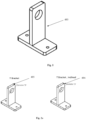
Figure 1 : illustrates the T bracket of the present invention. -
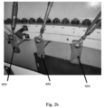
Figure 2 : illustrates the T bracket and inclined T bracket of the present invention. -
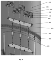
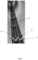
Figure 3 : illustrates the assembly in the tower. -
Figure 4 : illustrates the assembly in the tower. -
Figure 5 : illustrates the U-clamp and D-shackle of the assembly of the present invention. -
Figure 6 : illustrates the implementation of system of the present invention. -
Figure 7 : illustrates the arrangement of different components of system of the present invention. -
Figure 8 : illustrates the guide rollers of the present invention. -
Figure 9 : illustrates the pot magnet of the present invention. - For the purpose of promoting an understanding of the principles of the invention, reference will now be made to the embodiment illustrated in the drawings and specific language will be used to describe the same. It will nevertheless be understood that no limitation of the scope of the invention is thereby intended, such alterations and further modifications in the illustrated system, and such further applications of the principles of the invention as illustrated therein being contemplated as would normally occur to one skilled in the art to which the invention relates.
- It will be understood by those skilled in the art that the foregoing general description and the following detailed description are exemplary and explanatory of the invention and are not intended to be restrictive thereof. Throughout the patent specification, a convention employed is that in the appended drawings, like numerals denote like components.
- Reference throughout this specification to "an embodiment, "another embodiment, "an implementation, "another implementation" or similar language means that a particular feature, structure, or characteristic described in connection with the embodiment is included in at least one embodiment of the present invention. Thus, appearances of the phrase "in an embodiment, "in another embodiment, "in one implementation, "in another implementation, and similar language throughout this specification may, but do not necessarily, all refer to the same embodiment.
- The terms "comprises", "comprising", or any other variations thereof, are intended to cover a non-exclusive inclusion, such that a process or method that comprises a list of steps does not include only those steps but may include other steps not expressly listed or inherent to such process or method. Similarly, one or more devices or sub-systems or elements or structures proceeded by "comprises... a" does not, without more constraints, preclude the existence of other devices or other sub-systems or other elements or other structures or additional devices or additional sub-systems or additional elements or additional structures.
- In an embodiment, the system of the present invention provides support structure to retrofit power cables in the erected wind turbine.
- In an embodiment, the system (400) to retrofit power cables in an erected wind turbine comprises following components:
-
- a) plurality of T shaped brackets (495) and inclined T shaped brackets (494) mounted on a flange (490) of the wind turbine, by plurality of bolts wherein said T shaped brackets(494) and (495) is connected to plurality of plate (470) through plurality of turnbuckles (480) on its one end, said plate further allows the connection of wire rope (410) through the plurality of clamps (420, 420') on its other end to connect to the next plate; where said turnbuckles (480) provides tension to the wire ropes (410);
- b) plurality of hoisting winch mounted on a tower section of the erected wind turbine, facilitating the pulling of the power cables;
ii.) atleast a retrofit clamping unit comprising plurality of u bolts (402) having slotted rail profile around the horizontal length of the power cables, mounted along with the plurality of pot magnet/s (401), wherein the pot magnet comprises a thread portion (407) for mounting the pot magnets (401) on wall of erected wind turbine. - Importantly, the system comprises plurality of u bolts (402) and plurality of pot magnets (401) which together clamps the power cable at a specific distance in the erected wind turbine to damp the oscillation of the power cable; and plurality of guide rollers (500) mounted on a platform cut-out (520) where said guide rollers are mounted on an adjustable length slider (510) for passing the power cables through it, from the desired position according to the platform cut-out.
- In an embodiment, the retrofit clamping unit comprises atleast 2 magnets present at each 5 meter, wherein the pot magnet comprises 40KG of pull force with the diameter of 45mm and 12 mm thickness
- In another embodiment, the system comprises following components:
- a) a plurality of T shaped brackets (495), wherein the plurality of T shaped brackets are mounted on a flange (490) of the erected wind turbine by a plurality of bolts;
- b) a plurality of inclined T shaped brackets (494), wherein the plurality of inclined T shaped brackets (494) are mounted on the flange (490) of the erected wind turbine by the plurality of bolts;
- c) a plurality of wire ropes (410), wherein the plurality of wire ropes (410) is suspended between the plurality of t shaped bracket (495);
- d) a plurality of turnbuckles (480), wherein the plurality of wire ropes (410) are attached to the plurality of turnbuckles (480) and the plurality of turnbuckles (480) are configured to provide tension to the plurality of wire ropes (410);
- e) a plurality of hoisting winch, wherein the plurality of hoisting winch are mounted on a tower section of the erected wind turbine;
- f) a plurality of guide rollers, wherein the plurality of guide rollers is mounted on a platform cut-out and a plurality of power cables are passed through the plurality of guide rollers;
- g) a plurality of clamps (420, 420'), wherein the plurality of power cables are clamped at specific distance to the plurality of wire ropes (410) by using the plurality of clamps (420, 420'); and
- h) a rod assembly, wherein the rod assembly is configured to deviate the plurality of power cables from linear vertical path.
- In an embodiment, the system (400) to retrofit power cables comprises a retrofit power cable hanging unit (600) and a retrofit clamping unit. The retrofit power cable hanging unit includes T shaped brackets (495) and inclined T shaped brackets (494), turnbuckles (480), hoisting winch, clamps (420, 420'). Further, the clamping unit includes u bolts (402) and pot magnet/s (401).
- In an embodiment, wherein the T shaped brackets (495) and inclined T shaped brackets (494) are made of a very high strength steel.
- In an embodiment, the system to retrofit power cables in an erected wind turbine as claimed in claim 1, wherein a plurality of plates is fixed to the plurality of wire ropes (410).
- In an aspect of the present invention there is provided a method of operation of a system (400) to retrofit power cables in an erected wind turbine as claimed in claim 1, the method comprising steps of:
- d) Mounting T shaped brackets (495) and inclined T shaped brackets (494) on tower flanges (490) by using extended bolts and suspending a plurality of wire ropes (410) are in between special T shaped brackets (495) and inclined T shaped brackets (494);
- e) Tightening the wire ropes (410) with the turnbuckles (480) which act as tension inducing members and mounting hoisting winch at top tower section or in the section till which the power cables are needed to be pulled;
- f) Pulling the power cables are from the bottom to the top of section passing through guide rollers installed to the platform cut-outs of the erected wind turbine.
- In an embodiment, the system of the present invention comprises T brackets (495) and inclined T shaped brackets (494) which can be mounted on tower flanges (490) by using extended bolts. Wire ropes (410) are then suspended in between these special T brackets (495). These wire ropes are tensed with the turnbuckles (480) which act as tension inducing members. Further, suitable hoisting winch mounted at a suitable location in the top tower section or in the section till which the power cables are needed to be pulled. And then the power cables are pulled from the bottom to the top of section passing through guide rollers installed to the platform cut-outs.
- In an embodiment, the cables are clamped at specific distance to the wire ropes by using fiber reinforced PA clamps fixed to the plates installed to wire ropes. The clamping distance is defined by short-circuit force calculation. In this way, the wire ropes carry the load of the power cables. At each flange connection the wire ropes are relaxed to allow the weight to be contained and effectively transferred to the wire rope assembly of that section. For bending below the platform, a deviation rod assembly is designed which easily and effectively allows power cables to divert from linear vertical path.
- In an embodiment, the T shape are to be made with a very high strength steel configured to withstand the flange bolts preloads. The shape of the bracket allows it to be integrated on the tower flange readily along with flange bolts.
-
Fig. 1 andFig.2 shows the T brackets and inclined T brackets are to be made with a very high strength steel configured to withstand the flange bolts preloads. The flange of the tower of wind turbine usually have holes throughout its surface. The T brackets and inclined T brackets can be easily mounted on the flanges made at some specific distance inside the diameter of the tower. The mounting work of the T brackets and inclined T brackets by extended bolts does not require any welding work to fix both the brackets. Further, the T brackets inclined T brackets are made of high strength steel material which can stand the load of power cable at ease. The T shaped brackets (495) comprises a hole at top with diameter of 52mm and inclined T shaped brackets (494) comprises a hole at top with diameter of 39mm. Further, the dimensions of T shaped brackets and inclined T shaped brackets are 220 × 190 ×65 ×20mm. - Further, the holes on the surface of the flanges removes the requirement of any hole on the surface of the tower wall. This feature require less man hour for the installation of the power cable and also does not need to alter the already installed components inside the tower of the wind turbine.
- Further,
Fig.3 andFig.4 shows the assembly of different components of the system of the present invention. The system of the present invention comprises T brackets (495) and inclined T shaped brackets (494) which can be mounted on tower flanges (490) by using extended bolts. Wire ropes (410) are then suspended in between these special T brackets (495). These wire ropes are tensed with the turnbuckles (480) which act as tension inducing members. Further, suitable hoisting winch mounted at a suitable location in the top tower section or in the section till which the power cables are needed to be pulled. And then the power cables are pulled from the bottom to the top of section passing through guide rollers installed to the platform cut-outs. - Further, while pulling out the power cable through the tower of the wind turbine, the plurality of guide rollers helps the technicians to push or pull the heavy power cable. The guide rollers are provided at the platform cut out of the tower where the technician passes the power cable through the guide rollers. After pulling the power cable through the guide rollers the power cable, is clamped at the different position throughout the length of the tower of the wind turbine.
- Usually, the clamping operation of the power cable is performed by the plurality of clamps (420, 420'). The clamping distance is determined by the technicians to damp the oscillation of tower movement due to strong wind. wherein the plurality of power cables are clamped at specific distance to the plurality of wire ropes (410) by using the plurality of clamps (420, 420').
- Further, while pulling out the power cable throughout the length of the tower a rod assembly helps the technicians to deviate the power cable from the linear path. Further, the system includes plurality of u bolt (402) having slotted rail profile around its length. The u bolt (402) is mounted over plurality of pot magnet (401) and provide the user-friendly option of installing it inside the tower diameter with ease as no drilling operation is needed to mound the u bolt. Usually, the u bolt (402) and pot magnet (401) together clamps the power cable at a specific distance in the erected wind turbine to damp the oscillation of the power cable. Further,
Fig.9 shows the pot magnet (401) of the present invention, the pot magnet (410) includes a thread portion (407) for mounting the pot magnets (401) on wall of erected wind turbine. The pot magnet magnets have 40KG of pull force and diameter of 45mm and 12 mm thick. The pot magnet of the present invention is adapted to clamp the heavy power cables with ease without any need for any hole or welding work in the wall of tower of wind power system. - In an embodiment, the support structure of the present invention is easily adoptable, with no welding or hot works required. Further the support structure is feasible to install to an already installed or new Wind Turbine.
- In an embodiment, the support structure of the present invention is configured to be implemented for power upgrade of installed Wind Turbine which required additional runs of cables to be installed to compensate the increase in generation power.
Claims (10)
- A system (400) to retrofit power cables in an erected wind turbine comprising:i. atleast a retrofit power cable hanging unit comprising:a) plurality of T shaped brackets (495) and inclined T shaped brackets (494) mounted on a flange (490) of the wind turbine, by plurality of bolts wherein said T shaped brackets(494) and (495) is connected to plurality of plate (470) through plurality of turnbuckles (480) on its one end, said plate further allows the connection of wire rope (410) through the plurality of clamps (420, 420') on its other end to connect to the next plate; where said turnbuckles (480) provides tension to the wire ropes (410);b) plurality of hoisting winch mounted on a tower section of the erected wind turbine, facilitating the pulling of the power cables;ii. atleast a retrofit clamping unit comprising plurality of u bolts (402) having slotted rail profile around the horizontal length of the power cables, mounted along with the plurality of pot magnet/s (401), wherein the pot magnet comprises a thread portion (407) for being mounted on the wall of erected wind turbine;characterized in that:the plurality of u bolts (402) and plurality of pot magnets (401) together clamps the power cable at a specific distance in the erected wind turbine to damp the oscillation of the power cable; andplurality of guide rollers (500) mounted on a platform cut-out (520) where said guide rollers are mounted on an adjustable length slider (510) for passing the power cables through it, from the desired position according to the platform cut-out.
- The system (400) as claimed in claim 1, wherein the T shaped brackets (495) and inclined T shaped brackets (494) are made of a material comprising high strength steel.
- The system (400) as claimed in claim 1, wherein the T shaped brackets (495) comprises a hole at top with diameter of 52mm, while the inclined T shaped brackets (494) comprises a hole at top with diameter of 39mm.
- The system (400) as claimed in claim 1, comprises a rod assembly to deviate the plurality of power cables from linear vertical path to horizontal and vice-versa.
- The system (400) as claimed in claim 1, wherein the power cables are clamped at specific distance to the wire ropes (410) by using Fiber reinforced PA clamps (450) fixed to the plates installed to wire ropes (410).
- The system (400) as claimed in claim 1, wherein the clamping distance is defined by short-circuit force calculation wherein the wire ropes (410) carry the load of the power cables.
- The system (400) as claimed in claim 1, wherein the retrofit clamping unit, comprising atleast 2 magnets, present at each 5 meter, wherein the pot magnet comprises 40KG of pull force with the diameter of 45mm and 12 mm thickness
- A method of retrofitting the power cables in an erected wind turbine by the system as claimed in claim 1, the method comprising steps of:a) Mounting T shaped brackets (495) and inclined T shaped brackets (494) on tower flanges (490) by the extended bolts and suspending the plurality of wire ropes (410) in between the T shaped brackets (495);b) Tightening the wire ropes (410) with the turnbuckles (480), which acts as tension inducing members and mounting hoisting winch at top tower section or in the section till which the power cables are needed to be pulled;c) Pulling the power cables from the bottom to the top of section passing through guide rollers installed to the platform cut-outs of the erected wind turbine, for the retro-fitting.
- The method as claimed in claim 8, wherein the power cables are pulled from the bottom to the top of section passing through guide rollers installed to the platform cut-outs.
- The method as claimed in claim 8, wherein at each flange (490) connection, the wire ropes (410) are relaxed to allow the weight to be contained and to be effectively transferred to the wire rope assembly of that section.
Applications Claiming Priority (1)
| Application Number | Priority Date | Filing Date | Title |
|---|---|---|---|
| IN202311063713 | 2023-09-22 |
Publications (2)
| Publication Number | Publication Date |
|---|---|
| EP4528100A1 true EP4528100A1 (en) | 2025-03-26 |
| EP4528100B1 EP4528100B1 (en) | 2026-07-08 |
Family
ID=88837233
Family Applications (1)
| Application Number | Title | Priority Date | Filing Date |
|---|---|---|---|
| EP23210243.4A Active EP4528100B1 (en) | 2023-09-22 | 2023-11-16 | A system to retrofit power cables in an erected wind turbine and method thereof |
Country Status (1)
| Country | Link |
|---|---|
| EP (1) | EP4528100B1 (en) |
Citations (10)
| Publication number | Priority date | Publication date | Assignee | Title |
|---|---|---|---|---|
| US6945356B2 (en) * | 2000-11-29 | 2005-09-20 | Uniline Safety System Limited | Termination arrangement for a horizontal lifeline cable |
| JP2006246549A (en) | 2005-02-28 | 2006-09-14 | Mitsubishi Heavy Ind Ltd | Method of laying cable for wind energy conversion system, and cable laying device, and wind energy conversion system using it |
| US20090206610A1 (en) * | 2008-02-15 | 2009-08-20 | Negel Martin | Cable guard and method of installation |
| EP2762723A1 (en) * | 2013-01-31 | 2014-08-06 | Nordex Energy GmbH | Tower for a wind energy facility |
| US20150222106A1 (en) * | 2012-10-04 | 2015-08-06 | Hydac Accessories Gmbh | Apparatus for routing cables in wind turbines |
| CN205791366U (en) * | 2016-05-25 | 2016-12-07 | 正泰电气股份有限公司 | Semi-circular tube wind-power electricity generation conductor rail |
| EP2859228B1 (en) * | 2012-06-07 | 2019-02-27 | Vestas Wind Systems A/S | Tower cable arrangements for wind turbines |
| WO2019212474A1 (en) * | 2018-04-30 | 2019-11-07 | General Electric Company | Methods for refurbishing wind turbines |
| US10612527B2 (en) | 2017-06-13 | 2020-04-07 | General Electric Company | Methods for refurbishing wind turbines |
| US11371489B2 (en) | 2019-11-21 | 2022-06-28 | General Electric Renovables Espana, S.L. | Tower for a wind turbine with improved cable support in a vertical and horizontal arrangement |
-
2023
- 2023-11-16 EP EP23210243.4A patent/EP4528100B1/en active Active
Patent Citations (10)
| Publication number | Priority date | Publication date | Assignee | Title |
|---|---|---|---|---|
| US6945356B2 (en) * | 2000-11-29 | 2005-09-20 | Uniline Safety System Limited | Termination arrangement for a horizontal lifeline cable |
| JP2006246549A (en) | 2005-02-28 | 2006-09-14 | Mitsubishi Heavy Ind Ltd | Method of laying cable for wind energy conversion system, and cable laying device, and wind energy conversion system using it |
| US20090206610A1 (en) * | 2008-02-15 | 2009-08-20 | Negel Martin | Cable guard and method of installation |
| EP2859228B1 (en) * | 2012-06-07 | 2019-02-27 | Vestas Wind Systems A/S | Tower cable arrangements for wind turbines |
| US20150222106A1 (en) * | 2012-10-04 | 2015-08-06 | Hydac Accessories Gmbh | Apparatus for routing cables in wind turbines |
| EP2762723A1 (en) * | 2013-01-31 | 2014-08-06 | Nordex Energy GmbH | Tower for a wind energy facility |
| CN205791366U (en) * | 2016-05-25 | 2016-12-07 | 正泰电气股份有限公司 | Semi-circular tube wind-power electricity generation conductor rail |
| US10612527B2 (en) | 2017-06-13 | 2020-04-07 | General Electric Company | Methods for refurbishing wind turbines |
| WO2019212474A1 (en) * | 2018-04-30 | 2019-11-07 | General Electric Company | Methods for refurbishing wind turbines |
| US11371489B2 (en) | 2019-11-21 | 2022-06-28 | General Electric Renovables Espana, S.L. | Tower for a wind turbine with improved cable support in a vertical and horizontal arrangement |
Also Published As
| Publication number | Publication date |
|---|---|
| EP4528100B1 (en) | 2026-07-08 |
Similar Documents
| Publication | Publication Date | Title |
|---|---|---|
| EP1472458B2 (en) | Method of mounting elements in a wind turbine tower, wind tower suspension unit, system of mutually attachable members | |
| EP2187050B1 (en) | A tower of a wind turbine and a method for arranging a platform inside a tower | |
| KR101283790B1 (en) | Wind turbine generator and cable supporting structure for use therein | |
| EP2093417A2 (en) | Preassembled wind power plant tower section and method of transporting a tower section of a wind power plant | |
| CN102761083B (en) | Arrangement and the method for cable are installed | |
| EP2859228B1 (en) | Tower cable arrangements for wind turbines | |
| CN102762849A (en) | Wind turbine blade lowering apparatus | |
| CN103403344A (en) | Method for craneless wind turbine blade handling via a turbine hub | |
| US20190368473A1 (en) | Standardized platform arrangement of a wind turbine | |
| US9478962B2 (en) | Method and apparatus for reducing wind induced vibration damage to electrical power line towers | |
| EP3702616B1 (en) | Power cable installation in a wind turbine tower | |
| JP7271795B2 (en) | Attaching cables and other components to the wind turbine tower | |
| US10738431B2 (en) | Connection structure for a marine installation, marine installation and method of erecting a marine installation | |
| WO2012075607A1 (en) | Methods and systems for assembling wind turbine tower | |
| US20190145385A1 (en) | Offshore structure and method for attaching a tube or cable to an appliance of an offshore structure | |
| CN114879330B (en) | A fiber optic cable fixing device and a fiber optic cable fixing method | |
| US12276264B2 (en) | Cable guiding structure for a tower for a wind turbine, method for mounting a cable guiding structure, and wind turbine | |
| US20210277873A1 (en) | Wind turbine | |
| CN113803213B (en) | Cable laying method for tower barrel section, tower barrel and wind generating set | |
| EP4074964A1 (en) | Method for lifting a power cable inside of a tower of a wind turbine | |
| CN113586368A (en) | Platform for a wind turbine, wind turbine with a platform and method for assembling the same | |
| KR20220157889A (en) | Cable guiding in wind turbine towers | |
| CN108320824B (en) | Large-scale container internal reheater introducing device | |
| WO2025146328A1 (en) | A tower or tower section, wind turbine and method | |
| CN117722321A (en) | Wind power transmission and transformation system |
Legal Events
| Date | Code | Title | Description |
|---|---|---|---|
| PUAI | Public reference made under article 153(3) epc to a published international application that has entered the european phase |
Free format text: ORIGINAL CODE: 0009012 |
|
| STAA | Information on the status of an ep patent application or granted ep patent |
Free format text: STATUS: THE APPLICATION HAS BEEN PUBLISHED |
|
| AK | Designated contracting states |
Kind code of ref document: A1 Designated state(s): AL AT BE BG CH CY CZ DE DK EE ES FI FR GB GR HR HU IE IS IT LI LT LU LV MC ME MK MT NL NO PL PT RO RS SE SI SK SM TR |
|
| STAA | Information on the status of an ep patent application or granted ep patent |
Free format text: STATUS: REQUEST FOR EXAMINATION WAS MADE |
|
| 17P | Request for examination filed |
Effective date: 20250923 |
|
| RIC1 | Information provided on ipc code assigned before grant |
Ipc: F03D 80/80 20160101AFI20260209BHEP |
|
| GRAP | Despatch of communication of intention to grant a patent |
Free format text: ORIGINAL CODE: EPIDOSNIGR1 |
|
| STAA | Information on the status of an ep patent application or granted ep patent |
Free format text: STATUS: GRANT OF PATENT IS INTENDED |
|
| INTG | Intention to grant announced |
Effective date: 20260420 |
|
| GRAS | Grant fee paid |
Free format text: ORIGINAL CODE: EPIDOSNIGR3 |
|
| GRAA | (expected) grant |
Free format text: ORIGINAL CODE: 0009210 |
|
| STAA | Information on the status of an ep patent application or granted ep patent |
Free format text: STATUS: THE PATENT HAS BEEN GRANTED |
|
| AK | Designated contracting states |
Kind code of ref document: B1 Designated state(s): AL AT BE BG CH CY CZ DE DK EE ES FI FR GB GR HR HU IE IS IT LI LT LU LV MC ME MK MT NL NO PL PT RO RS SE SI SK SM TR |
|
| REG | Reference to a national code |
Ref country code: CH Ref legal event code: F10 Free format text: ST27 STATUS EVENT CODE: U-0-0-F10-F00 (AS PROVIDED BY THE NATIONAL OFFICE) Effective date: 20260708 Ref country code: GB Ref legal event code: FG4D |
|
| REG | Reference to a national code |
Ref country code: IE Ref legal event code: FG4D |
|
| REG | Reference to a national code |
Ref country code: DE Ref legal event code: R096 Ref document number: 602023019540 Country of ref document: DE |